

Page 1
KEY PRODUCT FEATURES
instruction manual
Minimo 11/16 Pro
Minimo 11/16 Pro is a miniature recessed
92 CRI LED luminaire offering 360º pan with
35º tilt.
Minimo 11 Pro 6W 513lm
Minimo 16 Pro 8.4W 665lm
These instructions cover procedures for all
versions of Minimo 11 & 16 Pro with bezels
including:
Fixed and adjustable congurations
Chamfered and at bezel congurations
Decorative and Pinhole apertures
IP20 and IP54 congurations
Trimless congurations
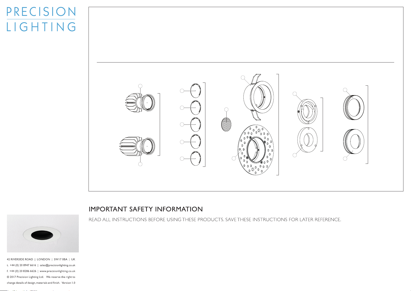
A 11 Series Module
B 16 Series Module
C 9 degree Optic
D 11 degree Optic
E 15 degree Optic
F 25 degree Optic
G 45 degree Optic
H Honeycomb Louvre
I Standard Housing
K Tilt ring
L Fixed ring
M Decorative Insert
N Pinhole Insert
J Trimless Housing
I
A
Module
B
C
D
Optic
E
F
G
H
J
K
Housing
L
Adjustability
M
Insert
N
1. All systems must be installed by a suitably
qualied professional only. Installations
must conform to national installation
and accident prevention regulations.
2. Ensure that the luminaire is switched off at
mains supply before installing or removing.
3. Do not install IP20 luminaires in a
damp or wet location. Do not install
any xture closer than 150mm (6
inches) from any combustible material.
4. To reduce the risk of re and burns, do
not install these systems where exposed
bare conductors can be shorted or
contact any conductive materials. Do not
conceal or extend exposed conductors
through a building wall.
5. Ensure all connections are tight. Bad
connections can cause overheating,
arcing and a potential re risk.
6. Wire supply connections must be made
with U.L or compatible testing agency-
approved connectors. Always use
appropriate optics and ensure they are
tted securely.
7. Install and use only as described in this
Precision Lighting manual.
8. Use Precision Lighting recommended
optics and accessories only.
10. Access to serviceable electrical
components should be kept available
for maintenance purposes.
11. Regular cleaning of these products is
important. Switch off at mains supply
and allow to cool before touching.
Clean ttings with a microbre cloth.
Then reconnect the power supply.
9. Luminaires may be hot, allow to cool
before touching.
© 2017 Precision Lighting Ltd. We reserve the right to change details of design, materials and nish. Version 02.17
Page 2
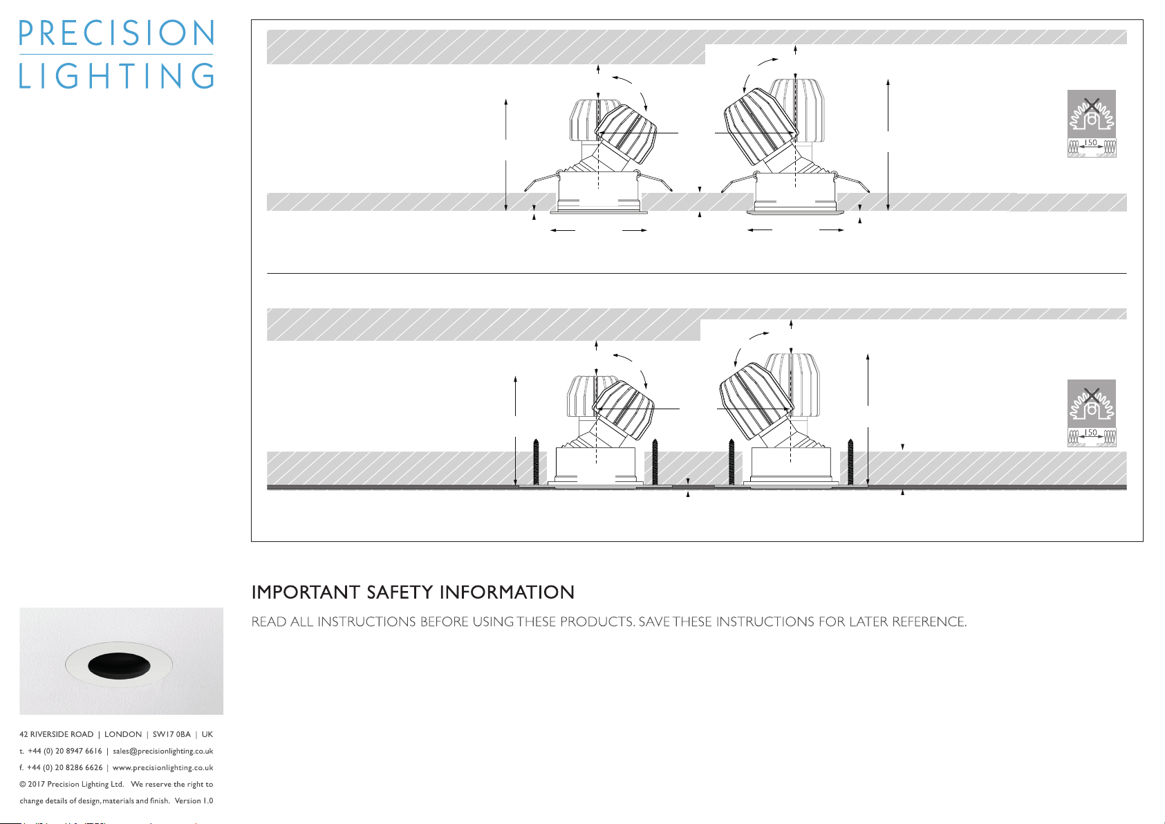
Minimo 11 Fixed/Tilt
20mm
3/4 inch
35° tilt
35° tilt
20mm
3/4 inch
Minimo 16 Fixed/Tilt
instruction manual
Minimo 11/16 Pro
Minimo 11/16 Pro is a miniature recessed
92 CRI LED luminaire offering 360º pan with
35º tilt.
Minimo 11 Pro - 6W, 513lm
Minimo 16 Pro - 8.4W, 665lm
These instructions cover procedures for
all versions of Minimo 11 Pro with bezels
including:
Fixed and adjustable congurations
Chamfered and at bezel congurations
Decorative and Pinhole apertures
IP20 and IP54 congurations
Trimless congurations
Springs parallel
Minimo 11 Fixed/Tilt Trimless
88mm
3 1/2 inch
86 mm
3 2/5 inch
1.5mm
1/20 inch
Cutout ø65mm
2 1/2 inch
ø76mm
3 inch
20mm
3/4 inch
Cutout ø76mm
3 inch
ø59mm
3 inch
35° tilt
135mm
5 1/3 inches
3-25mm
1/8 - 1 inch
135mm
5 1/3 inches
4mm
35° tilt
Cutout ø65mm
2 1/2 inch
ø76mm
3 inch
20mm
3/4 inch
3mm
1/8 inch
106mm
4 1/5 inch
106mm
4 1/5 inch
Minimo 16 Fixed/Tilt Trimless
3-25mm
1/8 - 1 inch
1. All systems must be installed by a suitably
qualied professional only. Installations
must conform to national installation
and accident prevention regulations.
2. Ensure that the luminaire is switched off at
mains supply before installing or removing.
3. Do not install IP20 luminaires in a
damp or wet location. Do not install
any xture closer than 150mm (6
inches) from any combustible material.
4. To reduce the risk of re and burns, do
not install these systems where exposed
bare conductors can be shorted or
contact any conductive materials. Do not
conceal or extend exposed conductors
through a building wall.
5. Ensure all connections are tight. Bad
connections can cause overheating,
arcing and a potential re risk.
6. Wire supply connections must be made
with U.L or compatible testing agency-
approved connectors. Always use
appropriate optics and ensure they are
tted securely.
7. Install and use only as described in this
Precision Lighting manual.
8. Use Precision Lighting recommended
optics and accessories only.
10. Access to serviceable electrical
components should be kept available
for maintenance purposes.
11. Regular cleaning of these products is
important. Switch off at mains supply
and allow to cool before touching.
Clean ttings with a microbre cloth.
Then reconnect the power supply.
9. Luminaires may be hot, allow to cool
before touching.
© 2017 Precision Lighting Ltd. We reserve the right to change details of design, materials and nish. Version 02.17
Page 3
WARNING Do not connect or disconnect under load.
Ensure driver has not been powered for a minimum of 1 minute before reconnecting the
LED module after disconnecting. Do not hot plug. Failure to follow this instruction will lead to
serious damage of the LED module and driver and will not be covered by warranty.
NOTE Maintain correct polarity when wiring. Incorrect wiring will cause serious damage and
will not be covered by warranty. Must be installed according to SELV regulations.
Wire specif ication: 22 AWG, ø0.65mm diameter double insulated teflon wire.
White - Positive Black - Negative
NOTE LED module is not site serviceable.
Tampering will cause damage and will not
be covered by warranty.
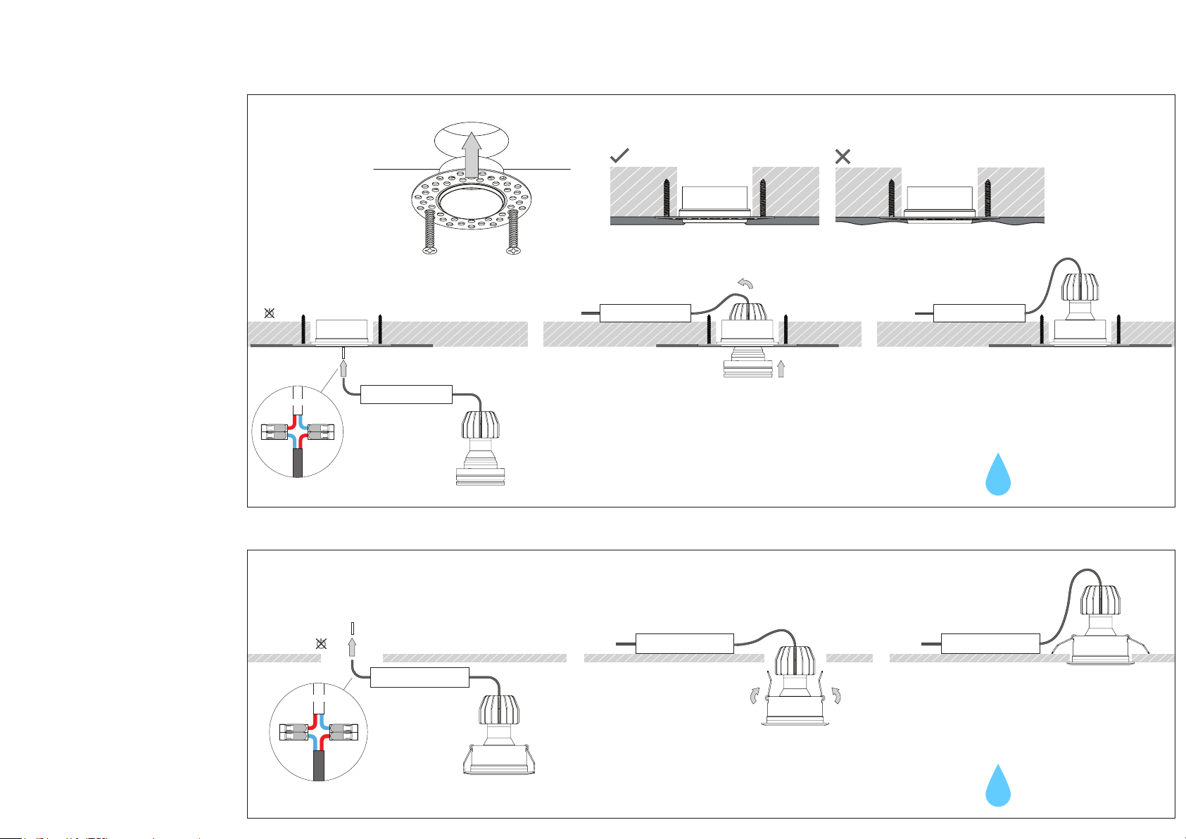
1. Installing the luminaire (Trimless)
WARNING switch off power to mains
before installation.
Remove LED module from tting.
Cut hole ø76mm (3 inches). Position
plaster-in ring and use appropriate
xings to secure to ceiling.
Note: Due to small luminaire size
drivers may need to be installed before
the trim is plastered in.
Trail mains cable through plaster in
ring. Apply plaster over plaster-in ring
and skim. Avoid covering wires and
connector with plaster. Cut around
inside of the aperature to ensure a neat
nish.
Once plaster is dry, connect driver to
luminaire.
Ensure the mains is switched OFF,
then connect the mains feed to the
driver.
Insert LED module into plaster-in ring
and add magnetic insert if required or if
removed during installation.
1A.
MAINS
For IP54 version the light
should rst be installed without
the magnetic insert.
1. Installing the luminaire (Trimmed)
WARNING switch off power to mains
before installation.
Cut ceiling hole at ø65mm (2 1/2 inch).
Note: Due to small luminaire size
drivers must be located remotely; cut out
is too small for dimmable drivers to pass
through.
Pull driver side connector through
hole and connect to the luminaire side
connector. See electrical instructions for
wiring schematic. Compatible drivers
listed in front page table.
Using installation springs, install xture
into the ceiling.
1B.
MAINS
For IP54 version the light
should rst be installed without
the magnetic insert.
© 2017 Precision Lighting Ltd. We reserve the right to change details of design, materials and nish. Version 02.17
Page 4
WARNING Do not connect or disconnect under load.
Ensure driver has not been powered for a minimum of 1 minute before reconnecting the
LED module after disconnecting. Do not hot plug. Failure to follow this instruction will lead to
serious damage of the LED module and driver and will not be covered by warranty.
NOTE Maintain correct polarity when wiring. Incorrect wiring will cause serious damage and
will not be covered by warranty. Must be installed according to SELV regulations.
Wire specif ication: 22 AWG, ø0.65mm diameter double insulated teflon wire.
White - Positive Black - Negative
NOTE LED module is not site serviceable.
Tampering will cause damage and will not
be covered by warranty.
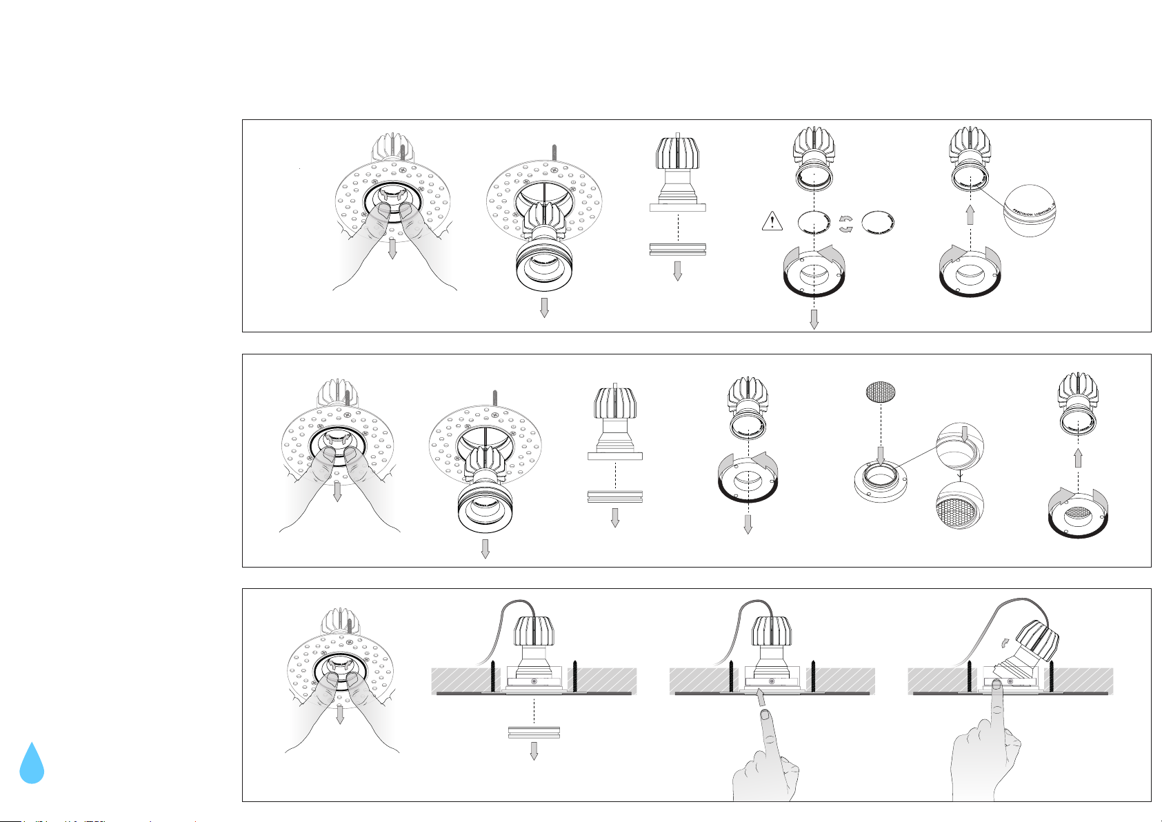
2. Changing beam angle
WARNING luminaire may be hot.
Allow to cool before touching.
Using two ngers or a tool remove the
magnetic insert and the LED module by
pulling sharply downwards.
Unscrew the tilt / xed magnetic ring
from the light engine to access the optic
disc.
When installing the optic disc the
text MUST be facing you.
3. Adding an accessory
Using two ngers or a tool remove the
magnetic insert and the LED module by
pulling sharply downwards.
Unscrew the tilt / xed magnetic ring
from the light engine to access the
accessory slot. The accessory must be
placed on the inside of the tilt / xed
magnetic ring.
2.
3.
4. Adjusting tilt angle and direction
Only valid for adjustable conguration
Using two ngers or a tool remove
the magnetic insert but leave the LED
module inside the trim. If the LED
module comes out with the inser t
please reinsert it into the trim.
The module can be pushed inwards to
rotate up to 35º. It can also be rotated
on the magnetic surface.
For IP54 version the tilt angle
should be set before the
magnetic insert is installed.
4.
© 2017 Precision Lighting Ltd. We reserve the right to change details of design, materials and nish. Version 02.17
Page 5
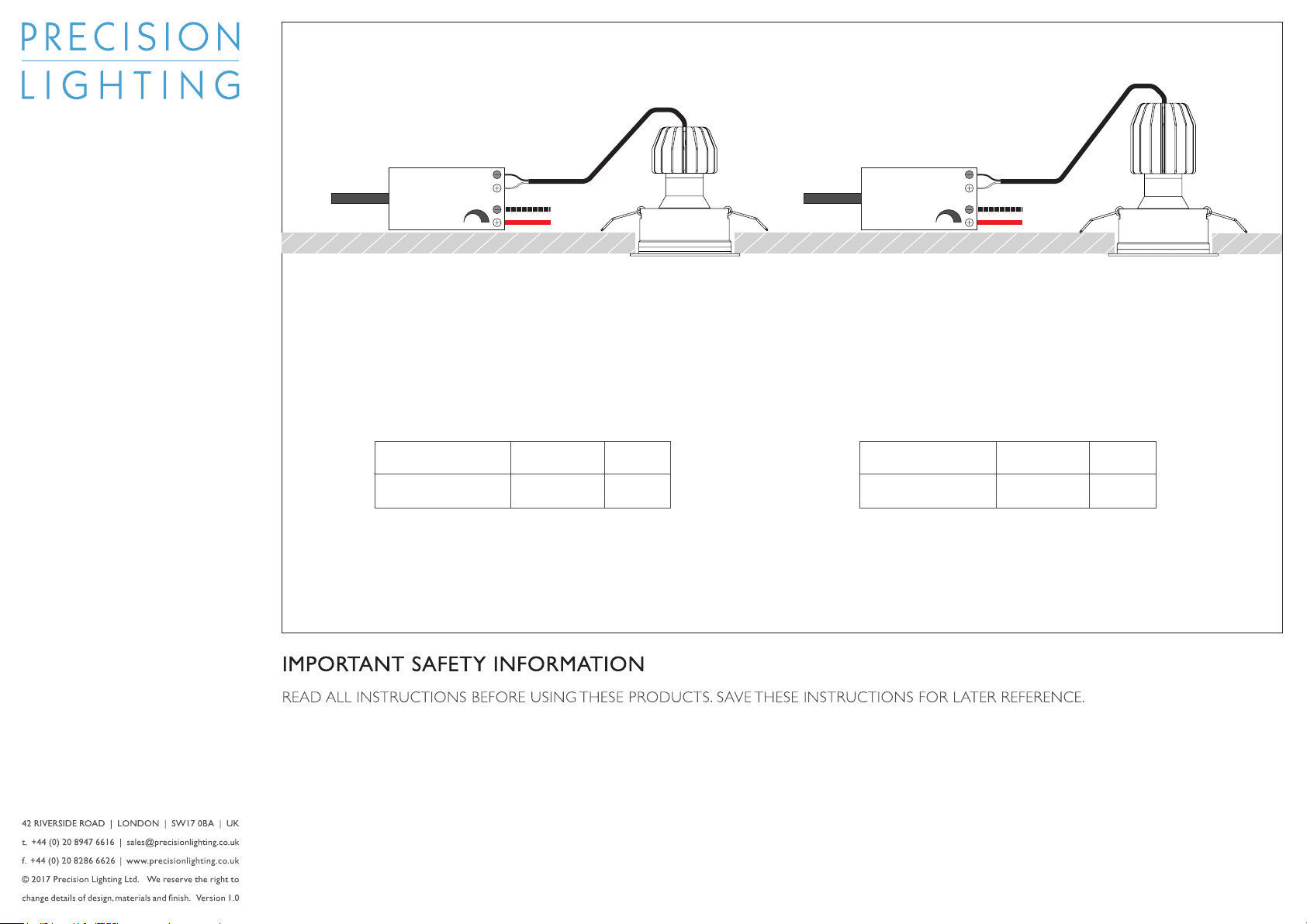
500mA Constant
Current Driver
Output /
Secondary
700mA Constant
Current Driver
Output /
Secondary
instruction manual
Minimo 11 / 16 Electrical
Installation
500mA or 700mA Constant
Current Driver.
WARNING
Do not exceed maximum number of
luminaires per driver wattage rating, see
driver datasheet for details.
Remote access required for driver.
These instructions are applicable to all
Minimo luminaires including:
605, 606, 607, 608 - Minimo 11 Pro Fixed
623, 624, 625, 626 - Minimo 11 Adjustable
631,632, 633, 634 -
635, 636, 637, 638
MAINS MAINS
1 -10V
/ DALI
WARNING mains supply to driver must
be OFF before connecting or disconnecting
fittings. Do not connect or disconnect
instruction will lead to serious damage
of the LED module and driver and will
not be covered by warranty.
under load.
Ensure driver has not been powered for a
minimum of 1 minute before reconnecting
the LED module after disconnecting.
Do not hot plug. Failure to follow this
COMPATIBLE
POWER SUPPLY
TCI Minijolly 1-10V 20 Driver
TCI Minijolly DALI 20 Driver
NOTE Wire specication: 22 AWG,
ø0.65mm diameter double insulated
teon wire.
White - Positive Black - Negative
ORDER CODE
PSCC-20-500-A-TC
PSCC-20-500-A-TC
LUMINAIRE
QUANTITY
1-2
1-2
1. Connect Minimo luminaires in series to
the driver LED outlet.
Maintain correct polarity when wiring.
Incorrect wiring will cause serious
damage and will not be covered by
warranty. Must be installed according to
SELV regulations.
COMPATIBLE
POWER SUPPLY
TCI Minijolly 1-10V 20 Driver
TCI Minijolly DALI 20 Driver
PSCC-20-500-A-TC
PSCC-20-500-A-TC
1 -10V
/ DALI
ORDER CODE
2. Wire 1-10V or DALI control to LED
driver.
Maintain correct polarity when wiring
dimming control wire. Incorrect wiring
will cause serious damage and will
not be covered by warranty. Must be
installed according to SELV regulations.
LUMINAIRE
QUANTITY
1-2
1-2
1. All systems must be installed by a suitably
qualied professional only. Installations
must conform to national installation
and accident prevention regulations.
2. Ensure that the luminaire is switched off at
mains supply before installing or removing.
3. Do not install these systems in a damp
or wet location, IP20 environments
only. Do not install any xture closer
than 150mm (6 inches) from any
combustible material.
4. To reduce the risk of re and burns, do
not install these systems where exposed
bare conductors can be shorted or
contact any conductive materials. Do not
conceal or extend exposed conductors
through a building wall.
5. Ensure all connections are tight. Bad
connections can cause overheating,
arcing and a potential re risk.
6. Wire supply connections must be made
with U.L or compatible testing agency-
approved connectors. Always use
appropriate optics and ensure they are
tted securely.
7. Install and use only as described in this
Precision Lighting manual.
8. Use Precision Lighting recommended
optics and accessories only.
before touching.
10. Access to serviceable electrical
components should be kept available
for maintenance purposes.
11. Regular cleaning of these products is
important. Switch off at mains supply
and allow to cool before touching.
Clean ttings with a microbre cloth.
Then reconnect the power supply.
9. Luminaires may be hot, allow to cool
© 2017 Precision Lighting Ltd. We reserve the right to change details of design, materials and nish. Version 02.17
 Loading...