

Precision Governors E-611 Installation Manual

PG
ENGINEERED CONTROL
ELECTRIC GOVERNOR
INSTALLATION MANUAL
Precision Governors E-611 Multipurpose
Controller.
E-611A with Terminal Strip P/N 9078
E-611B with 8 pin Plug P/N 9077

Precision Governors, LLC
PG ENGINEERED CONTROL SOLUTIONS
ENGINEERED CONTROL SOLUTIONS
Ph: 815-229-5300 Fax: 815-229-5342
1715 Northrock Ct
Rockford, IL 61103
www.pgcontrols.com
INTRODUCTION:
The E-611 controller is a general-purpose controller intended to control
engine speed for spark ignited or diesel engines. It is intended to feature more robust speed
regulation over the E-301 and E-361 products when retrofitted to system using other brands of
controllers and low resistance low current actuators.
For spark-ignited engines it may be configured to sense engine speed via ignition system frequency.
For both spark ignited and diesel engines, it may be configured to sense engine speed via magnetic
pickup sensing flywheel teeth.
The E-611 controller may be configured to govern speed in either discrete mode where the application
can select 1 of 4 speeds or it can be configured to operate in “ramp mode” where the controller has a
“increase speed” and a “decrease speed” input. This is similar to cruise control.
The E-611 controller requires no computer adjustments by the user. It features speed and gain
adjustments via potentiometer and governing style and speed signal frequency range determined by
setting of an 8 position DIP switch.
Discrete governing features 4 independent speed settings from 1000 to 3400 RPM.
Ramp governing features independent minimum, maximum, and initial ( engine off) speed settings
and a set speed ramp rate.
All governing modes feature gain, integral, and derivative adjustments.
The E-611 controller is 12 and 24 volt compatible. It is reverse polarity protected.
GENERAL
The following information is intended as an aid to properly installing a Precision Governors Model E-
611. Since these governors are used on a wide range of engines in many different applications, much
of the information is somewhat general in nature. If you need assistance concerning a specific detail
on your application, please consult Precision Governors Application Engineering at 815/229-5300.
These instructions presume no electrical test equipment other than a Multimeter for making the
electrical measurements called for on the following pages. If no meter is available, inexpensive but
adequate meters, are available from many consumer electronics stores such as Radio Shack.
Many "governor problems" turn out to be installation problems, particularly in first-time applications.
Careful attention to the directions provided will go far toward a successful installation made in the least
amount of time.
The E-611 is available with a 8 pin terminal strip ( E-611A) or with a 8 pin Packard Disconnect ( E611B.
QUICK-START INSTRUCTIONS
If you are experienced in installing and adjusting Electric Governors, follow these steps. Otherwise,
refer to the more detailed instructions, which begin on Page 8, starting with "Governor Assembly.”
1) Mount Controller in a dry, fairly cool location. Accessibility for adjusting is required.

Precision Governors, LLC
PG ENGINEERED CONTROL SOLUTIONS
ENGINEERED CONTROL SOLUTIONS
Ph: 815-229-5300 Fax: 815-229-5342
2) Wire per the appropriate system schematic. BE SURE TO OBSERVE CORRECT POLARITY.
Note some wire locations are different than the original controller.
3) Set the machine to command the various speeds and adjust. Turn CW to increase speed, CCW
to decrease speed.
4) Set Gain as required, using Gain pot. CW increases sensitivity. Load and unload the engine to
check for proper gain.
1715 Northrock Ct
Rockford, IL 61103
www.pgcontrols.com
CARBURETOR IDLE ADJUSTMENT
Engines with Integrated actuator / carburetor:
For carburetors with no idle adjustment stop screw, the mechanical idle is adjusted by disconnecting
the actuator wires then loosening the 3 actuator mounting screws and turning the actuator to obtain
the desired idle speed. This should be set with a fully warmed up engine and hydraulic system. This
setting must be at least 100 RPM below the lowest governed speed. Setting this too low may cause
the engine to stall during operation while setting this too high may create delays in engine governing or
cause the engine to continue running after power has been removed. Tighten the screws. After
turning off the engine, reconnect the actuator. Failure to turn off the engine may result in the engine
over-speeding.
Engines with separate actuator / carburetor:
Engines with separate actuator / carburetor should have the mechanical idle set by disconnecting the
actuator wires and adjusting engine speed with the carburetor stop screw. This should be set with a
fully warmed up engine and hydraulic system. This setting must be at least 100 RPM below the lowest
governed speed. Setting this too low may cause the engine to stall during operation while setting this
too high may create delays in engine governing or cause the engine to continue running
after power has been removed. Tighten the screws. After turning off the engine, reconnect the
actuator. Failure to turn off the engine may result in the engine over-speeding.
Diesel Engines:
Diesel engines typically have speed regulated electronically via an actuator controlling the fuel shutoff
lever or rack. On these engines, the mechanical governor should be set ABOVE the maximum
desired governed engine speed by 10% or more as speed can only be reduced by the electronic
governor.
MOUNTING--CONTROLLER
The replacement controller will require new mounting holes to be drilled.
The controller is water and weather resistant when the cover plate is filleted with RTV by the user.
However, attention to the following points will enhance its performance and reliability:
Select a reasonably cool, dry, and vibration free location.
The rear cover will probably need to be removed during set-up in order to make adjustments for
speed-setting and gain. You may wish to defer final installation until this is done.
After completing these adjustments, replace cover, and seal with a finger-fillet of RTV. Mount so
that water cannot pool on this cover. Mounting with this cover out of sight discourages "fiddling.”

Precision Governors, LLC
PG ENGINEERED CONTROL SOLUTIONS
ENGINEERED CONTROL SOLUTIONS
Ph: 815-229-5300 Fax: 815-229-5342
1715 Northrock Ct
Rockford, IL 61103
www.pgcontrols.com
WIRING
CAUTION:
Improper hook-up can damage electronics. Re-check wiring before applying power.
When retrofitting another manufacturer’s controller:
For retrofitting Barber Coleman controllers with terminal strips, wires may need to be moved.
For retrofitting Barber Coleman controllers with an 8-pin plug, the E-611 should not need any wiring
changes.
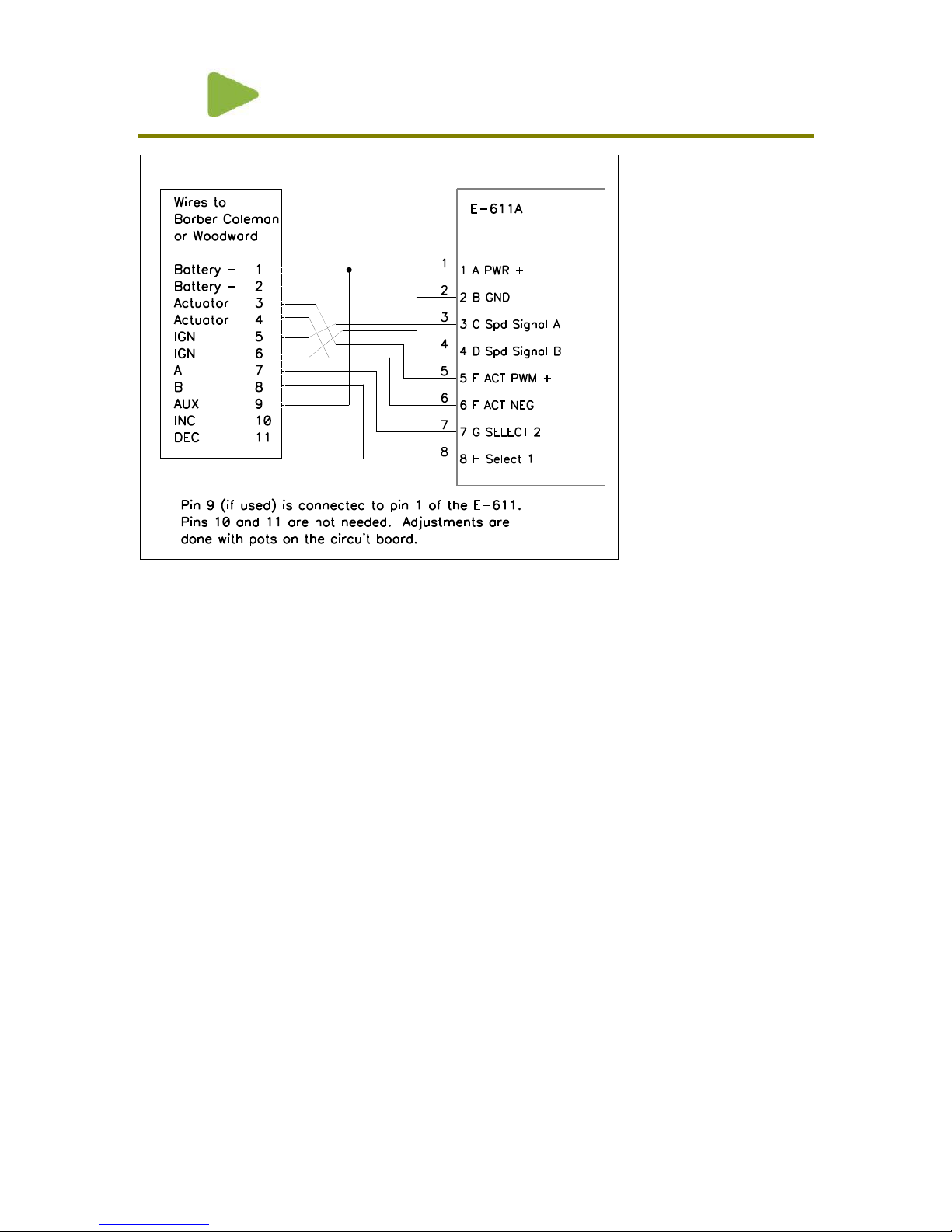
E-611A:
See Figure 1 for the controller wiring changes.
The original controller wires on pins 3 and 4 must be moved to the E-611 pins 5 and 6 (the order
is not important)
The original controller wires on pins 5 and 6 must be moved to the E-611 pins 3 and 4 (the order
is not important). Note, the controller does NOT use pin 4 but this pin is provided to fasten an
existing second DIS speed signal wire to an isolated pin. DO NOT short both speed signal wires
together.
Wires attached to pins 1, 2,7, and 8 of the original controller governor should be connected to the
same pins on the E-611.
If the machine had a wire connected to pin 9 of the Barber Coleman governor, this wire should be
connected to pin #1 of the E-611 in addition to the original power wire. This pin is simply a +
battery supply for the speed select switches.
E-611B Wiring:
Refer to Figure 2 for pin functionality. E-611B terminal “A” corresponds to E-611A pin 1,
terminal “B” to pin 2, terminal “C” to pin 3,etc. Again, the E-611B does not require wiring
modifications.
A properly functioning 12 volt engine electrical system will supply 13.5-14.8 VDC when the engine is
running. If wiring size is adequate, with good connections and proper grounds, you will get this reading
between the wires to terminals 1 & 2 of the 8 pin terminal strip when the Governor is controlling engine
speed. Verify this.
Precision Governors, LLC
PG ENGINEERED CONTROL SOLUTIONS
ENGINEERED CONTROL SOLUTIONS
Ph: 815-229-5300 Fax: 815-229-5342
1715 Northrock Ct
Rockford, IL 61103
www.pgcontrols.com
Figure 1 E-611A Retrofit Wiring
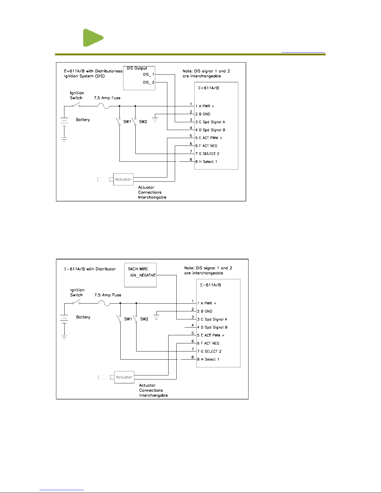
Distributor less Engine Wiring:
For use with distributor less engines, the controller’s speed signal inputs are connected to the DIS
ignition module coil output wires. Refer to engine schematics for the engine’s ignition wiring.
Normally these signals are the outer 2 leads (pins 1 and 3) of the coil pack 3 pin connector. Refer to
Figure 2: DIS wiring for the basic governing wiring schematic.
Precision Governors, LLC
PG ENGINEERED CONTROL SOLUTIONS
ENGINEERED CONTROL SOLUTIONS
Ph: 815-229-5300 Fax: 815-229-5342
Figure 2: DIS wiring
1715 Northrock Ct
Rockford, IL 61103
www.pgcontrols.com
Distributor Engine Wiring:
For use with distributor engines, the controller’s speed signal A input is connected to the ignition coil
NEGATIVE lead. Refer to Figure 3: Distributor Engine Wiring for the basic governing wiring
schematic.
Figure 3: Distributor Engine Wiring
Diesel Engine or spark ignited engine using a mag pickup:
 Loading...