

PD686 FM APPROVED & CSA CERTIFIED LOOP-POWERED METER
Conduit Hole
LONG SIDE VIEW
2.755" (70 mm)
0.790"
(20 mm)
0.750"
(19 mm)
2.56"
(65 mm)
TYPICAL HOLE LOCATION
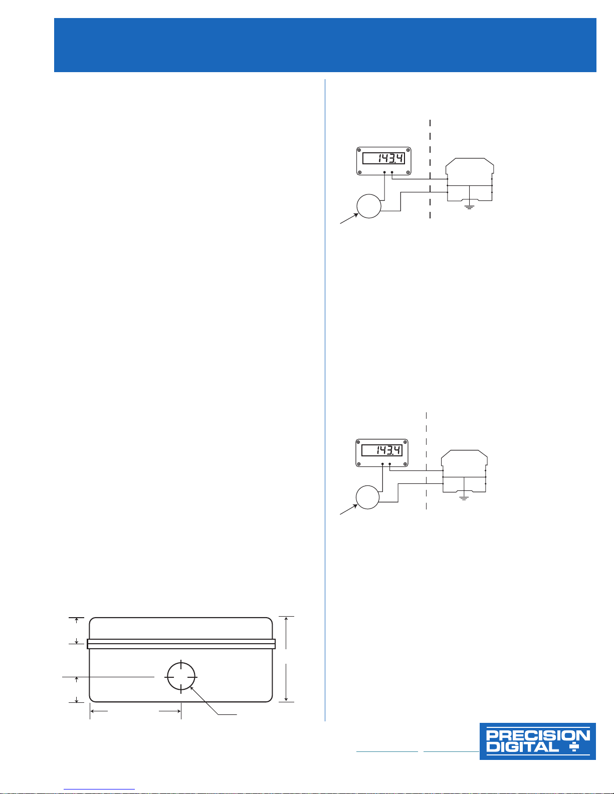
S-
S+
+
-
FM Entity Approved
positive polarity single
or dual-channel intrinsic
safety barrier used in an
approved configuration.
<1 ohm to Ground
Class I, Div 1, 2, Groups ABCD
Class II, Div 1, Groups EFG
Class II, Div 2, Groups FG
Class III,
Div 1, 2
Class 1,
Zone 0,
Group IIC
HAZARDOUS AREA NON-HAZARDOUS AREA
FM ENTITY A PPROVED TRANSMITTER INSTALLED PER TRANSMITTER
MANUFA CTURER'S HAZARDOUS LOCATION INSTALLATION DRAWING
PD686 ENTITY PARAMETERS:
U
i
: 30 V;
Ii : 175 mA; C
i
: 0; L
i
: 0; P
i
: 1.3 W
I.S.GROUND
PD686
S-
S+
+
-
CSA Entity Certified
positive polarity single
or dual-channel intrinsic
safety barrier used in an
approved configuration.
<1 ohm to Ground
Class I, Div 1, 2, Groups ABCD
Class II, Div 1, Groups EFG
Class II, Div 2, Groups FG
Class III,
Div 1, 2
HAZARDOUS AREA NON-HAZARDOUS AREA
CSA ENTITY CERTIFIED TRANSMITTER INSTALLED PER TRANSMITTER
MANUFA CTURER'S HAZARDOUS LOCATION INSTALLATION DRAWING
PD686-CSA ENTITY PARAMETERS:
V
max
: 30 V;
I
max
: 175 mA; C
i
: 0; L
i
: 0; P
i
: 1.3 W
I.S.GROUND
PD686-CSA
Order from:
C A Briggs Company
622 Mary Street; Suite 101
Warminster, PA 18974
Phone: 267-673-8117 - 800-352-6265
Fax: 267-673-8118
Sales@cabriggs.com - www.cabriggs.com
Intrinsic Safety Barrier Connections
SECTION AGENCY DESCRIPTION
1.0 General Notes
2.0 FM/CSA Conduit Installation Instructions
3.0 FM Single or Dual Channel Positive Polarity
Intrinsic Safety Barrier
4.0 CSA Single or Dual Channel Instrinsic Safety
Barrier Entity Installation
Note: FM AND CSA CoNtRoLLeD DoCUMeNt.
No CHANGeS WItHoUt PRIoR FM AND CSA APPRoVAL.
1.0 GENERAL NOTES
1.1 For Class II, Class III (Division 1 and 2) and NEMA/CSA
type 4X installations, use conduit hub which is listed/certified
for the environment in which the indicator is installed.
1.2 For Class II and III (Division 1 and 2) installations, field wiring
must enter the enclosure through a listed/certified dust-tight
conduit seal.
Control room equipment must not use or generate more than
1.3
250 VRMS or VDC.
1.4 US installations must be in accordance with ANSI/ISA
RP12.06.01 “Installation of Intrinsically Safe Systems for
Hazardous (Classified) Locations” and the National Electrical
Code (ANSI/NFPA 70). Canadian installations must be in
accordance with the Canadian Electrical Code, Part 1.
1.5 Hazardous location installation instructions for associated
apparatus (barrier) must also be followed when installing this
equipment.
1.6 For safe installation of a FM Approved/CSA Certified
transmitter in series with PD686 loop indicator, the hazardous
location installation instructions for the transmitter, PD686 loop
indicator, and associated apparatus (barrier) must be
PD686 indicator does not add capacitance or inductance to loop
1.7
under normal or fault conditions.
Substitution of components may impair hazardous location
1.8
safety.
compatible.
3.0 PD686 FM INSTALLATION WIRING DIAGRAM
Using single or dual channel intrinsic safety barrier
Application Notes:
3.1 U
> Uo of single channel barrier or Vt
i
> Io of single channel barrier or It of dual channel barrier
3.2 I
i
of dual channel barrier
3.3 Li plus interconnecting wiring < Lo of single or dual channel barrier
3.4 Ci plus interconnecting wiring < Co of single or dual channel barrier
It is not necessary to use intrinsic safety barriers when installing the
3.5
PD686 in Class I,II,III, Division 2, Groups ABCDFG, maximum input
voltage = 30 VDC.
4.0 PD686-CSA INSTALLATION WIRING DIAGRAM
Using single or dual channel intrinsic safety
barrier-entity installation
2.0 PD686 CONDUIT INSTALLATION INSTRUCTIONS
2.1 Remove the Display from the enclosure and connect ½"
conduit fittings to the hole provided. For enclosures without a
pre-drilled hole, the installer must make a hole in accordance
with the instructions for the particular conduit fitting being
installed.
2.2 Use only UL/CSA conduit hubs that are specified to maintain
NEMA 4X and Class II / Class III ratings.
Conduit hubs must be connected to the conduit prior to being
2.3
connected to the enclosure.
Enclosure must be mounted using the mounting holes
2.4
located in the base external to the equipment cavity.
Precision Digital corPoration
89 October Hill Rd • Holliston MA 01746 USA • Tel (800) 343-1001 • Fax (508) 655-8990
Application Notes:
4.1 Barrier parameters must meet the following requirements:
or Uo ≤ V
V
oc
Isc or Io ≤ I
Ca or C
La or Lo ≥ L
Po < P
i
or U
max
i
or I
max
≥
o
i
C
+ C
cable
i
+
L
i
cable
4.2 For CSA Certification, barrier and transmitter must be CSA Certified
with Entity Parameters and must be connected per manufacturer’s
instructions.
It is not necessary to use intrinsic safety barriers when installing the
4.3
PD686-CSA in Class I,II,III, Division 2, Groups ABCDFG, maximum
input voltage = 30 VDC.
LIM686-2_D 09/08
1155_L
www.predig.com
 Loading...