

Page 1

ConsoliDator®
Multi-Channel Controller
Instruction Manual
ConsoliDator 8 ConsoliDator 4
Eight 4-20 mA Inputs Four 4-20 mA Inputs
Eight 24 VDC @ 20 mA Four 24 VDC @ 20 mA
Two 4-20 mA Outputs Four 4-20 mA Outputs
Features and Highlights
Nine Form C 10 A Relays Powered from AC or DC
Four Pulse Inputs 32-Point Linearization
Four Digital Inputs RS-232 Modbus
Panel or wall mount Square Root Function
Sum and Difference
Functions
FREE Programming &
data logging software
Software
Included!
®
RTU
PC
PRECISION DIGITAL CORPORATION
89 October Hill Road • Holliston MA 01746 USA
Tel (800) 343-1001 • Fax (508) 655-8990
www.predig.com
Page 2

ConsoliDator Multi-Channel Controlle
r
Instruction Manual
Visit our Web Site
http://www.predig.com/
Disclaimer
The information contained in this document is subject to change without notice. Precision
Digital Corporation makes no representations or warranties with respect to the contents
hereof, and specifically disclaims any implied warranties of merchantability or fitness for a
particular purpose.
All trademarks mentioned in this document are the property of their respective owners.
Copyright © 2009-2012 Precision Digital Corporation
This document contains ratings and requirements necessary for proper installation.
Distribution of modified versions is strictly prohibited. Any text, chart, diagram, or table
reproduced must be reproduced in its entirety without alteration.
2
Page 3

ConsoliDator Multi-Channel Controlle
r
J
A
A
A
A
A
A
Instruction Manual
INTRODUCTION
The ConsoliDator is an easy to use multiple-channel controller. It accepts 4-20 mA inputs,
flow meter pulse inputs, and digital inputs. It is equipped with multiple relays, which all have
user-definable actions, 4-20 mA outputs, and Modbus protocol communication capabilities.
ORDERING INFORMATION
ConsoliDator Controllers
4-20
Model Mounting
PD980-8K9-15 Wall
PD981-8K9-15 Panel
PD940-8K9-15 Wall
PD941-8K9-15 Panel
Inputs
8 4 2 9
4 4 4 9
Accessories
Model Description
PDA2901 NEMA 4X Enclosure for PD981 or PD941 models.
PDA2904 NEMA 4X Large Enclosure for PD981 or PD941 models.
PDP2901 Sub Panel with Terminal Strips for PDA2901 Enclosure.
PDP2902 Low-Cost Sub Panel without Terminal Strips for PDA2901.
PDP2904 Sub Panel with Terminal Strips for PDA2904 Enclosure.
PDP2905 Low-Cost Sub Panel without Terminal Strips for PDA2904.
PDA6901 2" Pipe Mounting Kit for PDA2901 Enclosure.
PDA6902 2" Pipe Mounting Kit for PDA2904 Enclosure.
PDX6901 Snubber .01µF, 470Ω, Flexible Leads.
PDA7485-I RS-232 to RS422/485 Isolated Converter
PDA7485-N RS-232 to RS422/485 Non-Isolated Converter
PDA8232-N USB to RS-232 Converter
PDA8485-I USB to RS422/485 Isolated Converter
PDA8485-N USB to RS422/485 Non-Isolated Converter
PDA9232-01 ConsoliDator Null Modem Cable
PDA9232-02 RS-232 Computer Cable
Setup & Programming Services
Part Number Description
PDN-CSETUP2 Custom Setup & Programming
PDN-CERTCAL Certificate of Calibration
PDN-CERTCAL2 Certificate of Calibration with Data
PDA2901
Optional enclosure features quick-release
latches, a hinged front panel and internal space
for mounting additional components such as
relays and switches.
Pulse
Inputs
Model: PDP2901
Sub Panel for PDA2901 Enc
J7
POWER
GND
+
DC POWER
J8
RELAY
NO NCC
RELAY 9
GND HN
C POWER
4-20
Outputs
1
INPUT
K
K
K
C
O
E
E
E
Y
Y
Y
M
M
3
5
4
O
N
EXTERNAL KEYPAD
J2
OUTPUT
+
L
G
L
2
O
O
N
4
O
O
D
P
P
I
O
N
U
T
ANALOG
COMMON
OUTPUT 1
OUTPUT 2
INTERNAL
POWER
J3
INPUT
GND/
GND/
+
-
RET
RET
NALOG 5/
NALOG 6/
FLOW 1
FLOW 2
J4
INPUT
GND/
GND/
+
-
RET
RET
NALOG 1ANALOG 2ANALOG 3ANALOG 4
J5
RELAY
NO NCC
NO NCC
RELAY 5
RELAY 6
J6
RELAY
NO NCC
NO NCC
RELAY 1
RELAY 2
Relays
+
+
K
K
+
+
E
E
I
I
I
I
N
N
N
N
Y
Y
GG
P
P
P
P
1
2
U
U
U
U
T
T
T
T
4
3
1
2
DIGITAL INPUTS
L
G
L
+
L
L
L
L
O
O
2
O
O
O
O
N
4
O
O
O
O
O
O
D
P
P
P
P
P
P
I
O
I
O
O
I
N
N
N
U
U
U
T
T
T
ANALOG
ANALOG
ANALOG
COMMON
OUTPUT 3
OUTPUT 4
INTERNAL
POWER
GND/
GND/
+
-
+
-
+
-
RET
RET
NALOG 7/
NALOG 8/
FLOW 3
FLOW 4
GND/
GND/
+
-
+
-
+
-
RET
RET
NO NCC
NO NCC
RELAY 7
RELAY 8
NO NCC
NO NCC
RELAY 3
RELAY 4
PDP2901
Optional sub panel features terminal
strips for convenient installation of all
power, analog, and relay lines using up
to 8 AWG wire.
3
Page 4

ConsoliDator Multi-Channel Controlle
r
Instruction Manual
TABLE OF CONTENTS
INTRODUCTION ----------------------------------------------------------------------- 3
ORDERING INFORMATION -------------------------------------------------------- 3
TABLE OF CONTENTS -------------------------------------------------------------- 4
SPECIFICATIONS --------------------------------------------------------------------- 7
General ------------------------------------------------------------------------------------------- 7
4-20 mA Analog Inputs --------------------------------------------------------------------- 8
Flow Meter Pulse Inputs -------------------------------------------------------------------- 8
Digital Inputs ----------------------------------------------------------------------------------- 8
Relays -------------------------------------------------------------------------------------------- 9
4-20 mA Transmitter Outputs ----------------------------------------------------------- 10
Modbus® Serial Communications ----------------------------------------------------- 10
ConsoliDator® Software ------------------------------------------------------------------ 10
Compliance Information ------------------------------------------------------------------ 10
SAFETY INFORMATION ---------------------------------------------------------- 11
INSTALLATION ---------------------------------------------------------------------- 12
Unpacking ------------------------------------------------------------------------------------- 12
Wall Mounting ------------------------------------------------------------------------------- 12
Panel Mounting ------------------------------------------------------------------------------ 13
Connections ---------------------------------------------------------------------------------- 14
Power Connections ---------------------------------------------------------------------- 14
Input Signal Connections --------------------------------------------------------------- 15
4-20 mA Analog Input Connections ---------------------------------------------- 15
Flow Meter Pulse Input Connections --------------------------------------------- 16
Digital Input Connections ----------------------------------------------------------- 16
Analog Output Connections ------------------------------------------------------------ 17
Note: All inputs and outputs share a common ground. DO NOT power
inputs and outputs with the same power supply.Relay Connections -------- 17
Relay Connections ----------------------------------------------------------------------- 18
Switching Inductive Loads ---------------------------------------------------------- 18
Serial Communication Connections ------------------------------------------------- 19
Serial Communication Using RS-422/485 -------------------------------------- 19
External Keypad Connections --------------------------------------------------------- 19
NAVIGATING AND EDITING ----------------------------------------------------- 20
SETUP AND PROGRAMMING -------------------------------------------------- 21
Main Setup Menu --------------------------------------------------------------------------- 22
General Functions ------------------------------------------------------------------------ 22
Buzzer ----------------------------------------------------------------------------------- 22
Time Out -------------------------------------------------------------------------------- 22
Password -------------------------------------------------------------------------------- 22
Backlight --------------------------------------------------------------------------------- 23
Baud Rate ------------------------------------------------------------------------------- 23
Parity ------------------------------------------------------------------------------------- 23
Modbus ID ------------------------------------------------------------------------------ 23
4
Page 5

ConsoliDator Multi-Channel Controlle
r
Instruction Manual
Tx Delay --------------------------------------------------------------------------------- 23
Configuring 4-20 mA Inputs ------------------------------------------------------------- 24
Display Preferences --------------------------------------------------------------------- 24
Decimal Point -------------------------------------------------------------------------- 24
Units -------------------------------------------------------------------------------------- 24
Bargraph -------------------------------------------------------------------------------- 24
Input Scaling & Math Functions ------------------------------------------------------- 25
Linear ------------------------------------------------------------------------------------ 25
Square Root ---------------------------------------------------------------------------- 26
Exponent -------------------------------------------------------------------------------- 27
Integration Mode ---------------------------------------------------------------------- 28
Fixed Value ----------------------------------------------------------------------------- 28
Summation & Difference ------------------------------------------------------------ 28
Multi-Point Linearization ------------------------------------------------------------- 29
Sensor Input Setup ----------------------------------------------------------------------- 29
Setting Flow Meter Pulse Inputs ------------------------------------------------------- 30
Display Parameters ---------------------------------------------------------------------- 30
Input Configuration Parameters ------------------------------------------------------- 30
Programming Relays ---------------------------------------------------------------------- 31
Supervisory or Summary Alarm Modes --------------------------------------------- 31
High or Low Alarm Modes -------------------------------------------------------------- 31
Multi-Channel High or Low Alarm Modes ------------------------------------------ 32
High or Low Pulse Alarm Modes ----------------------------------------------------- 33
Trigger Alarm Mode ---------------------------------------------------------------------- 34
Annunciator High or Low Alarm Modes --------------------------------------------- 34
Plunger Lift by Differential Pressure Mode ----------------------------------------- 35
Plunger Lift by Time Mode ------------------------------------------------------------- 35
Lead-Lag Modes (Pump Alternation Control) ------------------------------------- 36
Linear Pulse Width Modulation Mode ----------------------------------------------- 38
Proportional Plus Integral Pulse Width Modulation Mode ---------------------- 39
Setting 4-20 mA Outputs ----------------------------------------------------------------- 40
Linear Scaling of 4-20 mA Output ---------------------------------------------------- 40
PID Control Using 4-20 mA Output -------------------------------------------------- 40
OPERATION -------------------------------------------------------------------------- 41
Manual and Simulation Modes --------------------------------------------------------- 45
Contrast Adjustment Control ----------------------------------------------------------- 46
MODBUS® SERIAL COMMUNICATION --------------------------------------- 47
Modbus Register Tables ----------------------------------------------------------------- 47
CONSOLIDATOR MONITOR SOFTWARE ----------------------------------- 52
Connecting to PC --------------------------------------------------------------------------- 52
Installing Software ------------------------------------------------------------------------- 52
Using ConsoliDator Monitor Software ----------------------------------------------- 52
Data Logging ------------------------------------------------------------------------------ 53
Programming Through Software ------------------------------------------------------ 53
OVERALL DIMENSIONS ---------------------------------------------------------- 54
TROUBLESHOOTING TIPS ------------------------------------------------------ 55
5
Page 6

ConsoliDator Multi-Channel Controlle
r
Instruction Manual
Table of Figures
Figure 1. Wall Mount Dimensions (PD980 & PD940) ..................................... 12
Figure 2. Panel Mount Dimensions (PD981 & PD941) ................................... 13
Figure 3. Power Connections .......................................................................... 14
Figure 4. Transmitter Powered by Ext. Supply or Self-Powered .................. 15
Figure 5. Transmitters Powered by ConsoliDator ......................................... 15
Figure 6. Three-Wire Transmitters Powered Externally ................................ 15
Figure 7. Flow Meter Pulse Input Connections .............................................. 16
Figure 8. Digital Input From Switch Closure .................................................. 16
Figure 9. Digital Input From Live Signal ......................................................... 16
Figure 10. 4-20 mA Output Powered by ConsoliDator .................................. 17
Figure 11. 4-20 mA Output Powered by External Supply .............................. 17
Figure 12. Relay Connections ......................................................................... 18
Figure 13. AC and DC Loads Protection ......................................................... 18
Figure 14. Low Voltage DC Loads Protection ................................................ 18
Figure 15. Serial Connections ......................................................................... 19
Figure 16. External Keypad Connections ....................................................... 20
Figure 17. Linear Response Graph ................................................................. 25
Figure 18. Square Root Response Graph ....................................................... 26
Figure 19. Exponent Response Graph............................................................ 27
Figure 20. Pulse Relay Timing Diagram ......................................................... 33
Figure 21. Linear PWM Relay Timing Example .............................................. 38
Figure 22. PD980 & PD940 Overall Dimensions ............................................. 54
Figure 23. PD981 & PD941 Overall Dimensions ............................................. 54
6
Page 7

ConsoliDator Multi-Channel Controlle
r
Instruction Manual
SPECIFICATIONS
Except where noted all specifications apply to operation at +25°C (77°F.)
General
DISPLAY Graphical: 4.75" x 3.5" (121 mm x 89 mm) LCD with backlight
DISPLAY UPDATE
RATE
PROGRAMMING
METHOD
CALIBRATION All ranges are calibrated at the factory.
PASSWORD Programmable password restricts modification of programmed
NON-VOLATILE
MEMORY
POWER AC: 90-264 VAC, 47 to 63 Hz, 20 VA
FUSE AC: Unit is protected internally. 5 A max, slow blow, 250 V min UL
ISOLATION &
GROUNDING
ENVIRONMENTAL Operating temperature range: 0 to 50°C (32 to 122°F)
CONNECTIONS Removable screw terminal blocks accept 12 to 24 AWG wire.
TIGHTENING
TORQUE
ENCLOSURE Type 1; Powder-coated steel; Color: warm gray
MOUNTING Wall Mount (PD980 & PD940): four screws/bolts
OVERALL
DIMENSIONS
WEIGHT 5.5 lb (2.5 kg)
WARRANTY
EXTENDED
WARRANTY
320 X 240 pixels; Bargraph: Twenty divisions; Numerical: ±999999 or
99’ 11.9” (feet and inches)
1 every 2 seconds
Front panel buttons, external buttons, PC with ConsoliDator software,
or Modbus registers.
settings and use of manual control functions.
Settings stored for a minimum of 10 years.
DC: 8-30 VDC, 15 W
Recognized external fuse recommended.
DC: 5 A max, slow blow, 250 V (or 50 V min) UL Recognized
external fuse recommended.
AC power is isolated from all inputs, outputs and relays to 1500 VAC.
Isolation to 500 VAC between analog inputs and analog outputs
requires powering analog outputs with external supply.
Signal and output power grounds are connected to earth (chassis)
ground. DC Power not isolated.
Storage temperature range: -40 to 60°C (-40 to 140°F)
Relative humidity: 0 to 90% non-condensing
*All functions operate down to -10°C (14°F.) LCD response is slower
below 0°C (32°F) and may need contrast adjustment to be readable.
DB9 male for serial connection.
Screw terminal connectors: 4.5 lb-in (0.5 Nm)
Panel Mount (PD981 & PD941): four screws/bolts
Cutout: 7.37" x 8.35" (187 mm x 212 mm)
Wall Mount 8.75" x 8.00" x 3.00" (222 mm x 203 mm x 76 mm)
(H x W x D)
Panel Mount 8.66" x 9.36" x 3.10" (220 mm x 238 mm x 79 mm)
(H x W x D)
1 year parts and labor
1 or 2 years, refer to Price List for details
7
Page 8

ConsoliDator Multi-Channel Controlle
r
Instruction Manual
4-20 mA Analog Inputs
INPUT 4-20 mA; minimum span of 1 mA
ACCURACY
TEMPERATURE DRIFT
INPUT FUNCTION Linear, Square Root, Programmable Exponent, Multi-Point
MATH FUNCTION Sum or difference of 2 or more channels.
TOTALIZER Calculates total based on rate and time base of second,
TOTALIZER RESET Via front panel buttons (password restricted)
DECIMAL POINT User selectable zero to six places with automatic overflow.
INPUT RANGE 4-20 mA, Minimum span of 1 mA
INPUT IMPEDANCE
NORMAL MODE
REJECTION
TRANSMITTER POWER
SUPPLY
ENGINEERING UNITS User selectable units or custom-entered units.
±0.03% of span 1 count
50 PPM/C from 0 to 50°C ambient
(up to 32), or Fixed Value
minute, hour, or day; stored in non-volatile memory every 5
minutes; supports linear inputs only.
130
Greater than 100 dB at 50/60 Hz.
Each input is equipped with +24 VDC current limited to
40 mA. External supply may be substituted.
Flow Meter Pulse Inputs
ACCURACY ±1 count for K-Factor > 1
SIGNAL RANGE 100 mVp-p to 15 Vp-p; 1 Hz to 10 kHz
K-FACTOR Programmable from 0.00001 to 999999 pulses/unit
DISPLAY OPTIONS Rate and total values displayed on screen.
ENGINEERING UNITS Show Total/Rate combinations:
RATE & TOTAL
DECIMAL POINT
TOTALIZER Calculates total based on rate. Reading stored in non-
TOTALIZER RESET Via front panel buttons (Password restricted)
Bargraphs user selectable to indicate either total or rate.
GAL & GPS, GAL & GPM, GAL & GPH, GAL & GPD, MG &
MGD, BBL & BPH, BBL & BPD, LTR & LPs, LTR & LPM,
LTR & LPH, LTR & LPD, CF & CFS, CF & CFM, CF &
CFH, CF & CFD, MCF & MCD.
Independent and user selectable from zero to six places
with automatic overflow.
volatile memory every 5 minutes for power-loss recovery.
Digital Inputs
INPUT TYPES Normally open switch: External excitation not required.
INPUT IMPEDANCE
SIGNAL REQUIREMENTS Minimum input pulse (closed contact or LO) duration: 1 sec
Open collector transistor: Open circuit voltage = 3 VDC
Closed Circuit Current = 18.5 mA
Switch closure or logic LO to terminals interpreted as "ON"
LO = 0 to 1 VDC, HI = 2.5 to 12 VDC
240
Maximum input pulse frequency: 30 cycles per minute
8
Page 9

ConsoliDator Multi-Channel Controlle
r
Instruction Manual
Relays
RATING SPDT (form C); rated 10 A @ 120/240 VAC or 5 A @ 28 VDC
ISOLATION 1500 VAC between coil and contacts
DEADBAND 0-100% of full scale, user selectable
ELECTRICAL NOISE
SUPPRESSION
ASSIGNMENT &
OPERATION
MANUAL
OVERRIDE
ACKNOWLEDGE Front panel ACK key resets relays in Supervisory, Summary and
TIME DELAY Programmable on/off delays, 0-999.9 sec
AUTO
INITIALIZATION
resistive load; 1/3 HP @ 120/240 VAC for inductive loads.
Minimum load: 50 mA for AC, 10 mA @ 5 VDC
An external suppressor (snubber) should be connected to each
relay contact switching inductive loads, to prevent disruption to
the microprocessor’s operation.
Recommended suppressor value: 0.01 µF/470 , 250 VAC
(Order: PDX6901.)
Any relay may be assigned to any analog or flow meter pulse
input channel. Multiple relays may be assigned to the same
channel. All relays are programmed independently.
High or Low Alarm: Assign to analog or pulse channel for on/off
relay control.
Multi-Channel High or Low Alarm: Assign two or more analog
channels. Indicate common high or low condition.
Annunciator High or Low: Assign to analog or pulse channel for
on/off relay control with reset capability from digital input switch.
Summary Alarm: Use to indicate any relay entering alarm state.
Supervisory Alarm: Use to indicate CPU failure or analog input
signal loss.
High or Low Pulse Action: Assign to analog or pulse input
channel for pulsing on/off timed relay control. Programmable
pulse width and delay.
Trigger: Assign to pulse channel for indication of user-defined
total increment. Programmable for scaled pulse output.
Plunger Lift: Assign to analog and/or pulse channels to control a
plunger lift system.
Lead-Lag Alternation (Sequence): Link multiple relays for
sequential operation. (Up to 9 relays.) Programmable override set
points to turn on up to 5 relays.
Pulse Width Modulation: Assign to analog or pulse channel for
on/off signal modulated by input. User selectable cycle time.
PI Control: Assign to analog or pulse channel for Proportional
plus Integral on/off modulated duty cycle. Manual tuning required.
Override any relay (Password restricted.) Relays do not respond
to input in this mode.
Annunciator Alarm Modes.
Independent for each relay.
When power is applied to the controller, relays will reflect the
state of the input to the controller.
9
Page 10

ConsoliDator Multi-Channel Controlle
r
Instruction Manual
4-20 mA Transmitter Outputs
OUTPUT RANGE 4.00 to 20.00 mA
CALIBRATION Factory calibrated for 4-20 mA
SCALING RANGE Any process range.
ASSIGNMENT &
OPERATION
ACCURACY
TEMPERATURE DRIFT
OUTPUT LOOP POWER Self powered or externally powered by 12 to 32 VDC
OUTPUT LOOP
RESISTANCE
ISOLATION 1500 V output-to-power line; 500 V output-to-input when
Assign to any analog or pulse input channel for linear
scaling or for manually tuned PID control output.
±0.05% F.S. 0.01 mA
50 PPM/C from 0 to 50C ambient.
Powered by controller: 10 to 600
Powered by external 12 VDC: 10 to 300
Powered by external 24 VDC: 10 to 600
Powered by external 32 VDC: 10 to 900
powered by external supply.
Output & Input drifts are separate.
Modbus® Serial Communications
COMPATIBILITY EIA-232
PROTOCOL Modbus RTU
DEVICE ADDRESS Programmable between 1 and 247
TRANSMIT DELAY Programmable between 0 and 300 ms
BAUD RATE Programmable from 1200 to 38400
DATA 8 bit (1 start bit, 1 stop bit)
PARITY EVEN, NONE with 1 stop bit, or NONE with 2 stop bits.
ConsoliDator® Software
SYSTEM
REQUIREMENTS
COMPATABILITY Separate versions for ConsoliDator 4 and ConsoliDator 8.
COMMUNICATION RS-232 using null-modem serial cable.
LOGGING
REPORTS
LOGGING REPORT Log to comma separated value (.csv) file compatible with
CONFIGURATION Configure inputs and outputs. Store ConsoliDator settings file on PC
Windows® 95/98/ME/NT4/2000/XP
Programmable between 1 sec. and 10 min.
spreadsheet applications such as Microsoft® Excel.
for programming other controllers or restoring settings.
Compliance Information
UL LISTED USA and Canada: UL 508 Industrial Control Equipment
UL FILE NUMBER E160849
10
Page 11

ConsoliDator Multi-Channel Controlle
r
SAFETY INFORMATION
Instruction Manual
!
CAUTION: Read complete
instructions prior to installation
and operation of the controller.
WARNING
Hazardous voltages present. Installation and service should be performed
only by trained service personnel.
WARNING: Risk of
electric shock.
11
Page 12

ConsoliDator Multi-Channel Controlle
r
Instruction Manual
INSTALLATION
Unpacking
Remove the instrument from its box. Inspect the packaging and contents for damage.
Report any damages to the carrier. If any part is missing or the controller malfunctions,
please contact your supplier or the factory for assistance.
Wall Mounting
(For PD980 & PD940 Models)
Obtain four #10 (M5) screws and nuts.
Prepare four 1/4" (6 mm) holes through mounting surface spaced as shown.
Allow at least 2” (5 mm) of free space on all sides so that the removable screw
terminals and DB9 connector may be accessed for wiring.
Secure instrument to surface.
Dia. 0.25" (6 mm) 4 places
7.25" (184 mm)
Figure 1. Wall Mount Dimensions (PD980 & PD940)
12
8.00" (203 mm)
Page 13

ConsoliDator Multi-Channel Controlle
r
:
Instruction Manual
Panel Mounting
(For PD981 & PD941 Models)
Obtain four #8 (M4) screws and nuts.
Obtain four washers with at least 5/16" (8 mm) O.D. If the device will be subjected to
vibration, lock washers are necessary.
Prepare four 1/4" (6 mm) clearance holes through mounting surface spaced as shown.
Prepare panel cutout.
8.35" W x 7.37" H (212 mm x 187 mm)
Center cutout vertically and horizontally with respect to holes.
Maximum allowable inner radii: 0.1" (2.5 mm.)
Remove all connectors.
Insert controller and secure to surface.
PANEL
CUTOUT
8.86" (225 mm)
Figure 2. Panel Mount Dimensions (PD981 & PD941)
4 CLEARANCE HOLES
Dia. 0.25" (6 mm)
8.16" (207 mm)
13
Page 14

ConsoliDator Multi-Channel Controlle
r
R
Instruction Manual
Connections
Connections are made to removable screw terminal connectors and a DB9 male serial
connector. They are located around the sides of the controller.
Use copper wire with 60°C or 60/75°C insulation for all
line voltage connections. Observe all safety regulations.
!
Electrical wiring should be performed in accordance with
all applicable national, state, and local codes to prevent
damage to the instrument and ensure personnel safety.
Power Connections
Power connections are made to one of the power terminal connectors. All units are capable
of being powered either by AC or by DC for the ranges specified.
CONNECT ONLY ONE OF THE POWER INPUTS
120-250 VAC Power (90 VAC min, 264 VAC max)
Use three-terminal power connector as shown in Figure 3.
Unit is protected internally. 5 A max, slow blow, 250 V min UL Recognized
external fuse recommended.
8-30 VDC Power
Use two-terminal power connector as shown in Figure 3.
5 A max, slow blow, 250 V (or 50 V min) UL Recognized external fuse
recommended.
AC POWER
120-250V
47-63 Hz
GND N H
DC POWE
8-30V
+ GND
AC HOT
AC NEUTRAL
EARTH GROUND
Figure 3. Power Connections
14
DC GROUND
DC +
Page 15

ConsoliDator Multi-Channel Controlle
r
A
Instruction Manual
Input Signal Connections
Input signal connections are made to terminal connectors, which are labeled individually on
the controller.
4-20 mA Analog Input Connections
Analog 4-20 Input connections are made to three-terminal connectors. The following figures
show examples for typical applications. Each of the 4-20 mA inputs may be connected in
any of the modes shown below.
ANALOG INPUT
GND
+
ANALOG INPUT
GND
+
++
External
Power
Supply
Figure 4. Transmitter Powered by Ext. Supply or Self-Powered
NALOG INPUT
GND
+
2-Wire
4-20 mA
Transmitter
2-Wire 4-20 mA
Self-Powered
ANALOG INPUT
GND
+
2-Wire
4-20 mA
Transmitter
Figure 5. Transmitters Powered by ConsoliDator
3-Wire 4-20 mA
Transmitter
+
Transmitter
+
Signal
+
ANALOG INPUT
GND
Power +
+
External Power
Supply
Figure 6. Three-Wire Transmitters Powered Externally
Signal -
3-Wire 4-20 mA
Transmitter
+
Signal +
15
Page 16

ConsoliDator Multi-Channel Controlle
r
G
R
T
T
Instruction Manual
Flow Meter Pulse Input Connections
Flow Meter Pulse Inputs are wired to two-terminal connectors. A square waveform is used
in the illustration, but the input is capable of reading many other types of signals within the
voltage and frequency ranges specified.
FLOW-METE
+
G
Signal Source
+
round
Figure 7. Flow Meter Pulse Input Connections
Digital Input Connections
Digital Inputs are wired to two-terminal connectors. Normally open switch contacts may be
used as shown in Figure 8. Figure 9 shows a Digital Input using an NPN open collector
transistor output from a live signal. Logic LO or switch closure appearing across the
terminals is interpreted as ON. When using an open collector transistor, a logic HI at the
base (marked "B" in Figure 9) will be interpreted as ON.
DIGITAL INPU
+
G
Switch Contact
Figure 8. Digital Input From Switch Closure
DIGITAL INPU
+
G
Live Signal
Source
C
B
+
-
Figure 9. Digital Input From Live Signal
16
E
Page 17

ConsoliDator Multi-Channel Controlle
r
Instruction Manual
Analog Output Connections
The following figures show examples for 4-20 mA transmitter output connections. Terminal
connectors are labeled individually on the side of the case. In order to obtain isolation from
analog inputs, outputs must be powered from an external supply as shown in Figure 11.
ANALOG OUTPUT
+24
LOOP IN
LOOP OUT
GND
+
Remote Display,
Chart Recorder, etc.
Figure 10. 4-20 mA Output Powered by ConsoliDator
ANALOG OUTPUTS
+24
LOOP IN
LOOP OUT
GND
External Power
Supply
+
+
Remote Display,
Chart Recorder, etc.
Figure 11. 4-20 mA Output Powered by External Supply
Note: All inputs and outputs share a common ground. DO NOT
inputs and outputs with the same power supply.
17
power
Page 18
ConsoliDator Multi-Channel Controlle
r
A
A
g
Instruction Manual
Relay Connections
Relay connections are made to three-terminal connectors labeled on the side of the case.
RELAY OUTPUT
NO - C - NC
Figure 12. Relay Connections
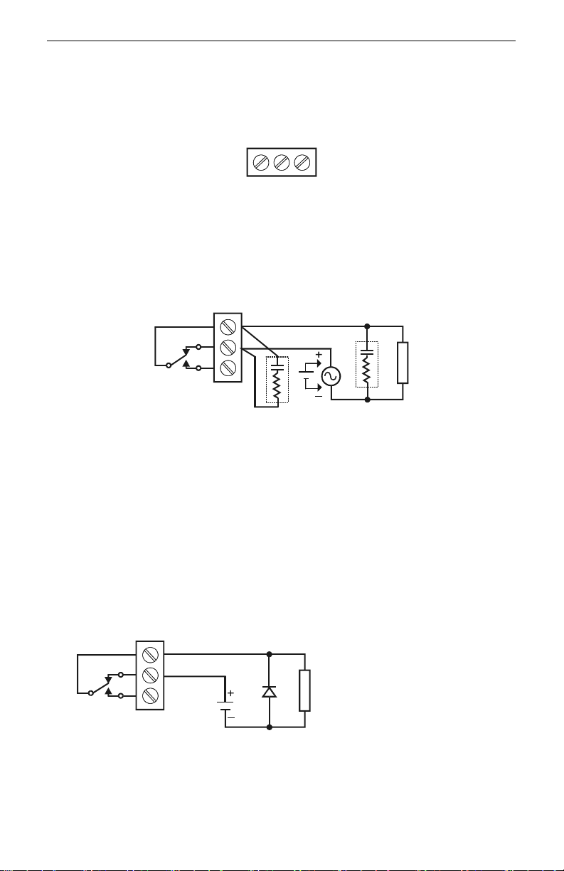
Switching Inductive Loads
The use of suppressors (snubbers) is strongly recommended when switching inductive
loads to prevent disrupting the microprocessor’s operation. The suppressors also
prolong the life of the relay contacts. Suppression can be obtained with
resistor-capacitor (RC) networks assembled by the user or purchased as complete
assemblies. Refer to the following circuits for RC network assembly and installation:
NO
C
Figure 13. AC and DC Loads Protection
Choose R and C as follows:
R: 0.5 to 1 for each volt across the contacts
C: 0.5 to 1 µF for each amp through closed contacts
Notes:
1. Use capacitors rated for 250 VAC.
2. RC networks may affect load release time of solenoid loads. Check to confirm
proper operation.
3. Install the RC network at the instrument's relay screw terminals. An RC network
may also be installed across the load. Experiment for best results.
NO
C
Use diode with a reverse breakdown
L
voltage two to three times the circuit
O
voltage and forward current at least
D
as lar
Figure 14. Low Voltage DC Loads Protection
RC Networks Available from Precision Digital
RC networks are available from Precision Digital and should be applied to each relay
contact switching an inductive load. Part number: PDX6901.
L
O
D
e as the load current.
18
Page 19
ConsoliDator Multi-Channel Controlle
r
Instruction Manual
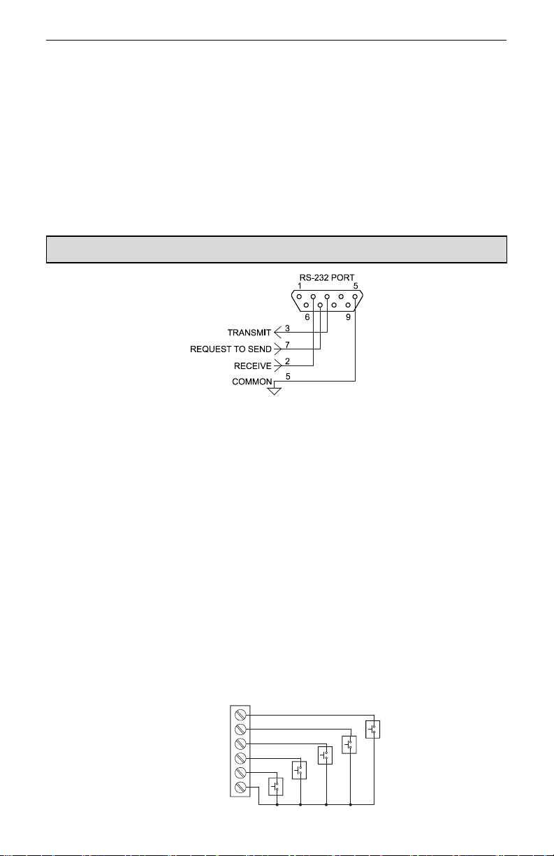
Serial Communication Connections
A DB9 male connector is the port for RS-232 serial communication (using Modbus
protocol.) The ConsoliDator can be connected to Data Circuit-Terminating Equipment
(DCE) such as a radio transmitter with a regular straight-through serial cable. In cases
where connecting to Data Terminal Equipment (DTE), such as a PC, a Female-Female Null
Modem cable is necessary. Many computers are equipped with at least one 9-pin RS-232
serial port. For distances up to 50 ft, a shielded serial or null-modem cable is adequate.
More information can be found in Modbus Serial Communications (page 47)
When connecting the ConsoliDator
to change the ConsoliDator's parity parameter to "NONE - 8N2," for None parity, 2 stop
bits.
A null modem cable looks similar to a standard serial cable, but internally the transmit and receive lines
cross unlike in a standard serial cable and for Computer-to-ConsoliDator, both ends must be Female.
Serial Communication Using RS-422/485
For long distances or noisy environments RS-422 and RS-485 offer superior
performance compared to RS-232. Differential signals can help nullify the effects of
ground shifts and induced noise signals that can appear as common mode voltages
on a network. RS-422 was designed for greater distances than RS-232. In its simplest
form, a pair of converters from RS-232 to RS-422 (and back again) can be used to
form an “RS-232 extension cord." Distances to 4000 ft. can be reached with RS-422.
In an application that requires more than two devices to be networked, the RS-232
data must be converted to a serial format that allows for multiple devices, such as
RS-485. For example, you can connect two or more ConsoliDators to a single
computer by converting all devices to RS-485, but only one ConsoliDator with RS-232.
Data Converters Available from Precision Digital
Serial converters available from Precision Digital support a wide range of
devices. Please reference part number PDA7485 when requesting information.
®
to a PC via the PDA8232, it is strongly recommended
Figure 15. Serial Connections
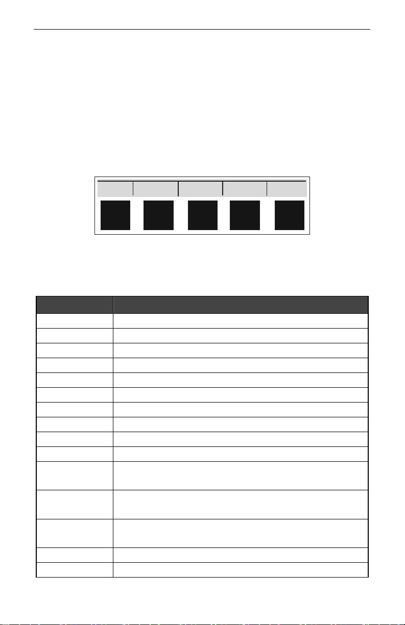
External Keypad Connections
Normally open pushbuttons may be wired to the six-terminal external keypad connector for
use when the front panel of the controller is not accessible. Keys 1 through 5 refer to the
front buttons in order from left to right.
KEY 1
KEY 2
KEY 3
KEY 4
KEY 5
EXTERNAL KEYPAD
COMMON
19
Page 20
ConsoliDator Multi-Channel Controlle
r
Instruction Manual
Figure 16. External Keypad Connections
NAVIGATING AND EDITING
The device displays various screens throughout programming and operation. Functions are
programmed within their respective menu screens in many cases accompanied by user
prompts.
Soft-Keys and Buttons
The unit is equipped with five buttons located below the display. The function of each
button corresponds to its soft-key, which appears at the bottom of the screen. Buttons
assume different functions, which change according to the screen in view.
SETUP AUTO ACK NEXT
Selections are marked by a cursor, which appears on screen as an arrowhead. The keys
below are used to navigate through menus and edit settings. Other special keys appear
throughout the programming process.
Key Action
ACK
EDIT
ENTER
EXIT
MANUAL / AUTO
RST
SAVE
SETUP
SIM
NEXT
+
-
Acknowledge relay(s)
Modify selection
Execute current selection
Quit present screen or mode
Toggle operation modes
Reset total
Store setting to memory
Enter main setup menu
Enter simulation mode
Scroll through operation screens
Move cursor up when navigating menus
Scroll up through characters & values when editing settings
Move cursor down when navigating menus
Scroll down through characters & values when editing settings
Move cursor right when navigating menus
Move to next character space when editing settings
Increase setting
Decrease setting
20
Page 21
ConsoliDator Multi-Channel Controlle
r
SETUP AND PROGRAMMING
There is no need to recalibrate the instrument when first
received from the factory.
The device is factory calibrated prior to shipment, for all
input types. The calibration equipment is certified to NIST
standards.
Overview
Setup and programming are done
through the front buttons or ConsoliDator
Monitor Software. After power and signal
connections have been completed and
verified, apply power to the instrument.
Inputs, outputs, and relays are
configured individually. It is
recommended that all inputs be
configured before outputs and relays are
programmed.
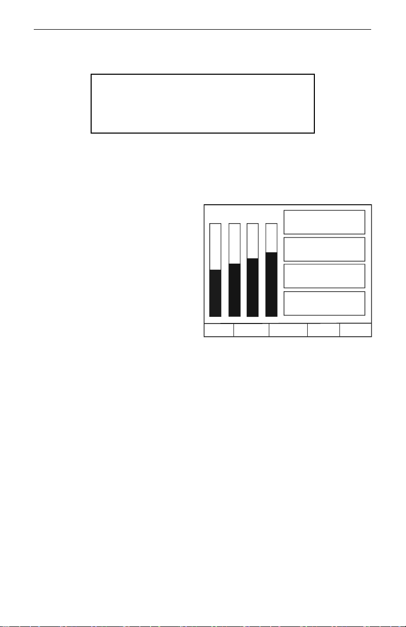
Shown to the right is a typical screen that
appears upon first power-up. Actual
screens will vary with the amount of
inputs initially detected.
For information on button functions, see
NAVIGATING AND EDITING (page 20.)
To load software and program from a
PC, please familiarize yourself with the
ConsoliDator Monitor Software
(page 52) before you continue with
device setup.
Press SETUP key to begin.
Instruction Manual
Ch1 Ch2 Ch3 Ch4
SETUP AUTO ACK NEXT
Ch 1:
Ch 2:
Ch 3:
Ch 4:
12.000
13.000
14.000
15.000
mA
mA
mA
mA
mA
21
Page 22
ConsoliDator Multi-Channel Controlle
r
O
B
Instruction Manual
Inputs
Channel #1
Channel #2
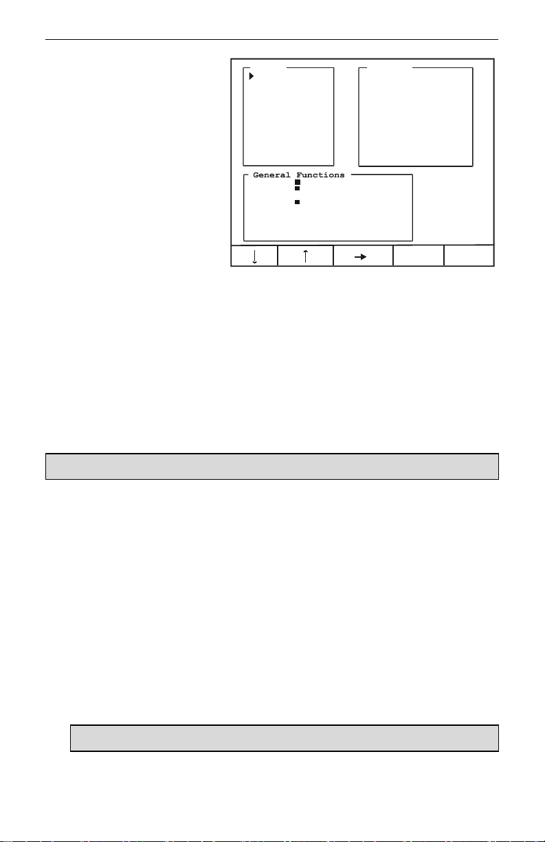
Main Setup Menu
The main setup menu is the
access point during the
programming process for setting
up Inputs, Outputs, and General
Functions. The number of inputs
and outputs shown on this screen
are determined by what your
particular model is equipped with.
Use arrows to navigate and the
ENTER key to select.
Channel #3
Channel #4
Channel #5
Channel #6
Channel #7
Channel #8
Flow Meter #1
Flow Meter #2
Flow Meter #3
Flow Meter #4
uzzer: ON OFF
T-Out: ON OFF
Change Password
Save BL: YES NO
Baud Rate: 19200 bps
Parity: EVEN - 8E1
Modbus ID: 1
Tx Delay: 0 ms
Adjust Contrast
Inputs
The Inputs box shown on this screen lists the 4-20 mA Channels and Flow Meter inputs.
Individual channel setup is covered in detail in the next sections: Configuring 4-20 mA
Input (page 24) and Setting Flow Meter Pulse Inputs (page 30.)
Outputs
The Outputs box shown on this screen lists the relay and analog output channels available.
Output setup is covered in Programming Relays (page 31) and Setting 4-20 mA Outputs
(page 40.)
General Functions
utputs
Alarm Relay #1
Alarm Relay #2
Alarm Relay #3
Alarm Relay #4
Alarm Relay #5
Alarm Relay #6
Alarm Relay #7
Alarm Relay #8
Alarm Relay #9
Analog Out #1
Analog Out #2
EXITENTER
The General Functions box contains various options and serial communication settings.
If you are beginning a first-time setup, please read the brief descriptions below and if you are not sure of
the settings, you may skip them and return after the controller’s operation is explained in later sections.
Use the arrows keys to move cursor to parameters in the General Functions box. Use
ENTER to select a parameter.
Buzzer
Buzzer sounds to indicate an active relay if [ON] is selected. Select [OFF] to disable.
Time Out
Manual mode time-out options are related to Manual and Simulation Modes
(page 45.) When T-Out is set to [ON] the controller will return to Automatic mode after
being left alone for 5 minutes in Manual mode. When [OFF] is selected, the controller
will only switch modes if a key is pressed and then the password (if enabled) is
entered.
Password
Select [Change Password] to enter a new password up to ten characters or to change
an existing password. The operator will be required to enter this password to access
setup or to manually override relays. It is recommended to enter the password after
setup and programming is completed.
To disable a previously programmed password: Enter setup, select [Change Password] and leave
the Password entry box blank.
22
Page 23

ConsoliDator Multi-Channel Controlle
r
Instruction Manual
Backlight
Selecting [YES] under Save BL automatically turns the backlight off if no buttons are
pressed for five minutes. This is recommended unless it is necessary to have the
backlight constantly on. When [NO] is selected the backlight is always on.
Baud Rate
Select any available baud rate.
Parity
Select [EVEN – 8E1] for Even parity, 1 stop bit.
Select [NONE – 8N2] for None parity, 2 stop bits.
Select [NONE – 8N1] for None parity, 1 stop bit.
Modbus ID
Specify an address for Modbus communication.
Tx Delay
Specify a serial data transmission delay (response.)
Place cursor at the channel you want to set and press ENTER.
23
Page 24

ConsoliDator Multi-Channel Controlle
r
I
Instruction Manual
Configuring 4-20 mA Inputs
The Analog Input setup screen is used
to configure the 4-20 mA analog inputs.
Each channel has a separate menu. All
4-20 mA inputs can be configured using
the information provided in this section.
In this menu, the Sensor box displays
the live input reading in mA, and the
Value box displays the scaled
engineering units corresponding to the
sensor input. You can verify your
scaling parameters with this
relationship.
Display Preferences
Begin configuring the input by naming the channel (e.g. “Tank 1”.) This name appears on
screen to identify the channel during operation.
Move cursor to Channel ID and press EDIT. Use arrow keys to scroll through characters
and move to the next position. Press SAVE to store new setting to memory.
Next, set display options. Move cursor to Configure Display Parameters and press ENTER.
The box that appears contains the parameters for decimal point, engineering units, and
bargraph extents for this channel. Use EDIT and arrow keys. Remember to press SAVE
when finished.
Decimal Point
Format specifies the decimal point position for this channel. Use the arrow keys to
shift left or right (zero to five places.)
Units
Select from any available engineering units or choose to enter a combination of
characters by pressing the CUSTOM key. If this channel is to be used for integration
totalizing, do not select rate units as the integration time base is added separately.
Bargraph
Max Value and Min Value are used to set the span of the bargraph (in scaled
engineering units) for this channel. The bargraph will appear 100% full at Max Value
and 0% at Min Value.
Analog Input: 1
nput Type: 4-20 mA Transmitter
Function: NONE - Linear
Channel ID: Analog 1
Configure Function Parameters
Configure Sensor Input
Configure Display Parameters
Sensor: Value:
12.00 mA 12.000 mA
EXIT
24
Page 25
ConsoliDator Multi-Channel Controlle
r
)
Instruction Manual
Input Scaling & Math Functions
The ConsoliDator is capable of various functions for scaling the 4-20 mA inputs. Linear
Square Root, Programmable Exponent, and Integration are two-point scaling functions.
Multi-Point is capable of handling up to 32 scaling points and requires that the ConsoliDator
Monitor Software be used to enter these points.
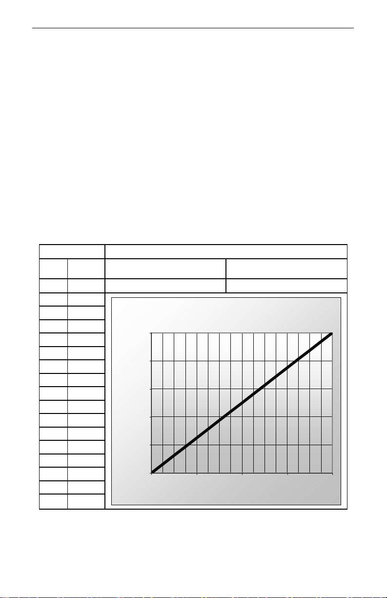
Linear
Linear mode refers to basic 2-point scaling of a 4-20 mA signal in engineering units.
The graph in Figure 17 shows the display response based on example scaling
parameters. For this mode select [Linear] from Function options, then follow Sensor
Input Setup (page 29) to enter your scaling parameters.
Process Scaling Parameters
Input
10.00 37.50
11.00 43.75
12.00 50.00
13.00 56.25
14.00 62.50
15.00 68.75
16.00 75.00
17.00 81.25
18.00 87.50
19.00 93.75
20.00 100.00
Display
(mA)
4.00 0.00
5.00 6.25
6.00 12.50
7.00 18.75
8.00 25.00
9.00 31.25
(%)
High Value: 100.00 Low Value: 0.00
Sensor: 20.00 Sensor: 4.00
Linear Response
100.00
80.00
60.00
40.00
Display (%
20.00
0.00
4.00 8.00 12.00 16.00 20.00
Sen so r ( m A)
Figure 17. Linear Response Graph
25
Page 26
ConsoliDator Multi-Channel Controlle
r
)
Instruction Manual
Square Root
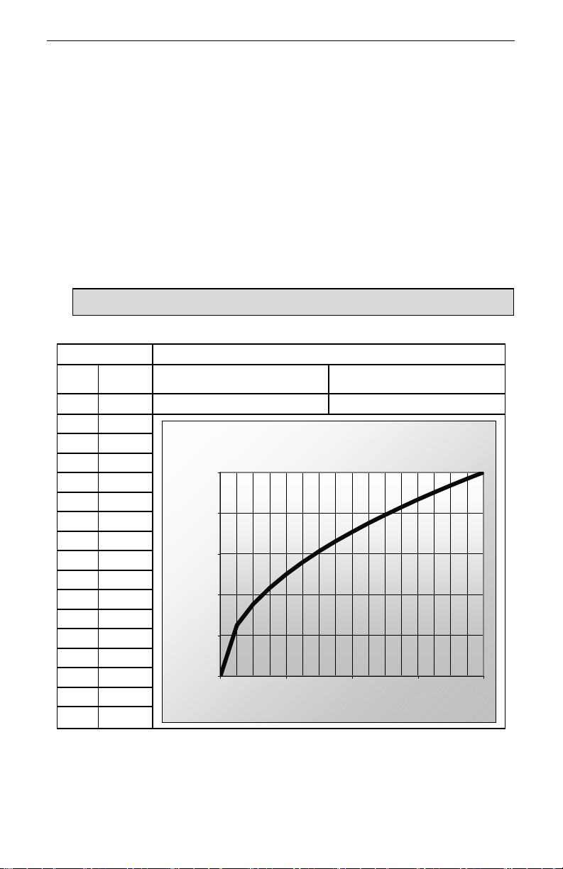
Square root mode refers to 2-point scaling with square root extraction typically used to
linearize the signal from a differential pressure transmitter and display the flow rate in
engineering units. The graph in Figure 18 shows the display response based on
example scaling parameters. For this mode select [Square Root] from Function
options.
The square root mode supports low-flow cutoff which can be used to suppress
readings below a programmed value. Below the cutoff value, the controller will display
“0”. To enter a cutoff value, select Configure Function Parameters. Press EDIT and
use arrow keys to change the value. Press SAVE when complete.
Follow Sensor Input Setup (page 29) to enter your scaling parameters.
Note: An input that goes below the Low Value parameter results in a display of “-999999”
indicating underrange condition. This can be prevented using the cutoff feature.
Process Scaling Parameters
Input
10.00 61.24
11.00 66.14
12.00 70.71
13.00 75.00
14.00 79.06
15.00 82.92
16.00 86.60
17.00 90.14
18.00 93.54
19.00 96.82
20.00 100.00
Display
(mA)
4.00 0.00
5.00 25.00
6.00 35.36
7.00 43.30
8.00 50.00
9.00 55.90
(%)
High Value: 100.00 Low Value: 0.00
Sensor: 20.00 Sensor: 4.00
Square Root Response
100.00
80.00
60.00
40.00
Display (%
20.00
0.00
4.00 8.00 12.00 16.00 20.00
Sen so r ( m A)
Figure 18. Square Root Response Graph
26
Page 27
ConsoliDator Multi-Channel Controlle
r
)
Instruction Manual
Exponent
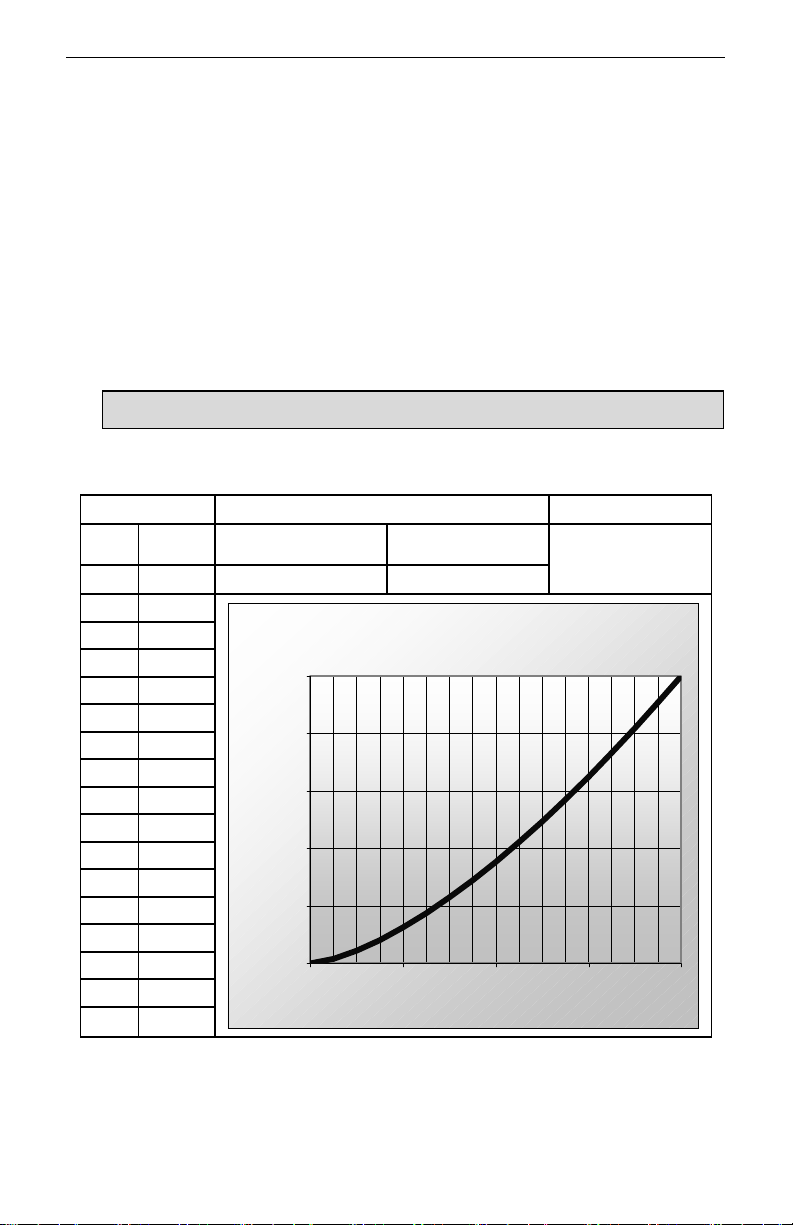
Exponent mode refers to 2-point scaling with programmable exponent (programmable
root) extraction typically used in open-channel flow applications with weirs and flumes
to linearize the signal from a level transmitter and display the flow rate in engineering
units. The graph in Figure 19 shows the display response based on example
parameters and exponent of “1.5”. For this mode select [Exponent] from Function
options. To enter an exponent, select Configure Function Parameters. Press EDIT and
use arrow keys to change the value. Press SAVE when complete.
The exponent mode supports low-flow cutoff which can be used to suppress readings
below a programmed value. Below the cutoff value, the controller will display “0”. To
enter a cutoff value, select Configure Function Parameters. Press EDIT and use arrow
keys to change the value. Press SAVE when complete.
Follow Sensor Input Setup (page 29) to enter your scaling parameters.
Note: An input that goes below the Low Value parameter results in a display of “-999999”
indicating underrange condition. This can be prevented using the cutoff feature.
Process Scaling Parameters Exponent
Input
10.00 22.96
11.00 28.94
12.00 35.36
13.00 42.19
14.00 49.41
15.00 57.00
16.00 64.95
17.00 73.24
18.00 81.85
19.00 90.77
20.00 100.00
Display
(mA)
4.00 0.00
5.00 1.56
6.00 4.42
7.00 8.12
8.00 12.50
9.00 17.47
(%)
High Value: 100.00 Low Value: 0.00
Sensor: 20.00 Sensor: 4.00
Ex ponent Response
100.00
80.00
60.00
40.00
Display (%
20.00
0.00
4.00 8.00 12.00 16.00 20.00
Sen so r ( m A)
Figure 19. Exponent Response Graph
1.50000
27
Page 28
ConsoliDator Multi-Channel Controlle
r
F
C
I
F
C
I
Instruction Manual
Integration Mode
Integration mode is able to totalize from any 4-20 mA channel over a time base of
second, minute, hour, or day. During operation, the channel’s display screen shows
bargraph total, numeric total, and numeric rate. To begin setup, select from the
following under Function options [Integration: SEC], [Integration: MIN], [Integration:
HOUR], or [Integration: DAY]. Follow Sensor Input Setup (page 29) to enter your
scaling parameters for the rate.
Note: Integration Mode is available for 2-point linear calibration only.
Fixed Value
Fixed Value mode may be used to create a constant display as if a steady signal is
applied to the input, without requiring a transmitted signal. Controller outputs assigned
to this channel will respond the same way it would with a constant signal. Any
transmitted source connected on the corresponding input is ignored while fixed value
mode is selected. To begin setup, select [Fixed Value] from Function options. Next,
select Configure Function Parameters. In the box that appears, enter a value in
engineering units by pressing EDIT and using the arrow keys. Press SAVE when
complete and then EXIT to return to input menu.
Summation & Difference
Summation mode begins with a linearly scaled input, but adds the ability to link one or
more separate channels for addition to its own display. Difference mode follows the
same link principle, but subtracts one or more channels from itself. During operation,
the channel that is used to set-up the link is the one that displays the sum or
difference. Verify the appropriate channel has been selected. i.e. To display a
summation for Channel 1 plus another channel, make sure you are in Analog Input: 1
setup screen. Remember to scale the other channels that you have chosen to link.
First, enter your scaling parameters. Reference Sensor Input Setup (page 29.)
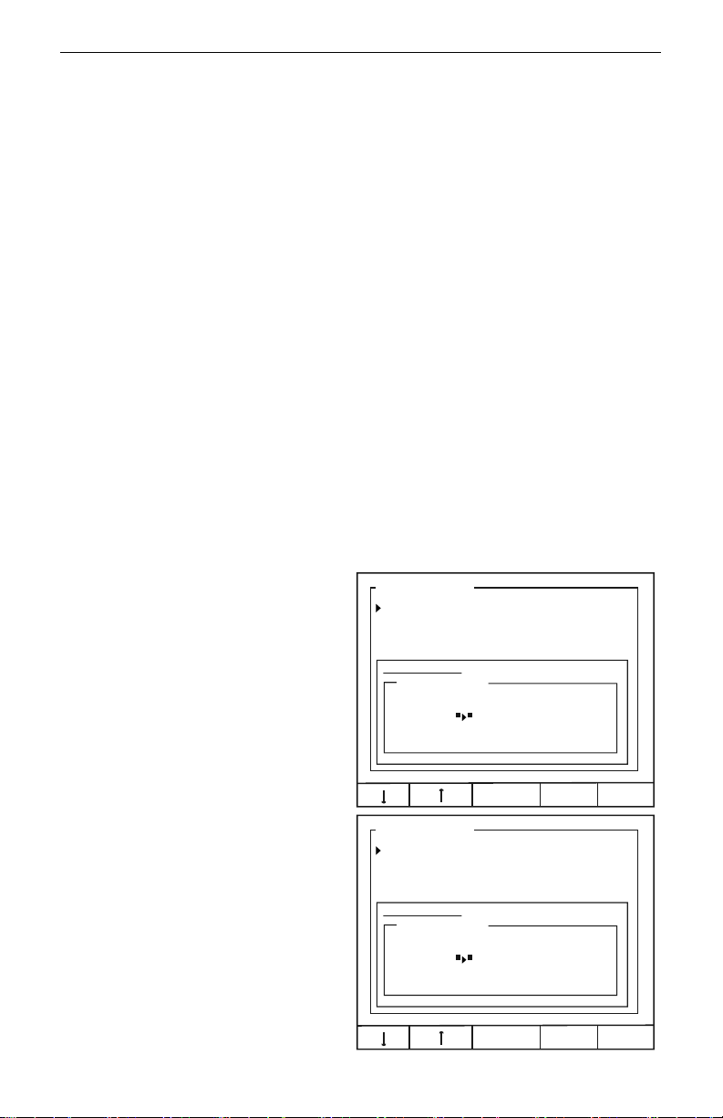
For Summation, select
[Summation], from Function
options. Select Configure Function
Parameters from the Analog Input
setup screen. In the Function
Setup box shown to the right, use
arrow keys and ON/OFF key to
select channels to be linked. The
settings shown in the screen to the
right are programmed to add
Channel 2 to Channel 1.
Analog Input: 1
nput Type: 4-20 mA Transmitter
Function: Summation
Channel ID: Analog: 1
unction Setup:
Assign Channels:
hannel = 1+2+3+4+5+6+7+8
Link:
For Difference, select [Difference],
from Function options. Select
Configure Function Parameters
from the Analog Input setup
screen. In the Function Setup box
shown to the right, use arrow keys
and ON/OFF key to select
channels to be linked. The settings
shown in the screen to the right
Analog Input: 1
nput Type: 4-20 mA Transmitter
Function: Difference
Channel ID: Analog: 1
unction Setup:
Assign Channels:
hannel = 1-2-3-4-5-6-7-8
Link:
OFF EXIT
are programmed to subtract
Channel 2 from Channel 1.
OFF EXIT
28
Page 29
ConsoliDator Multi-Channel Controlle
r
Instruction Manual
Multi-Point Linearization
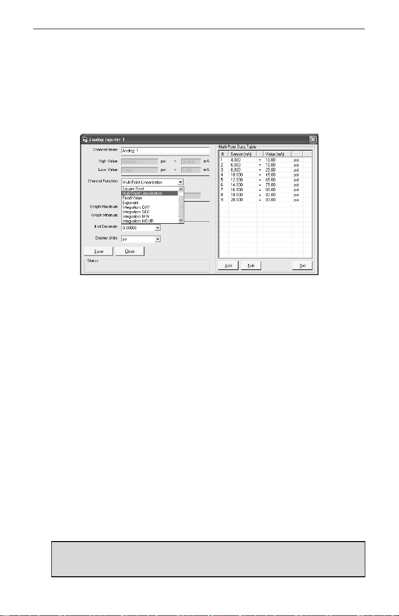
Multi-Point Linearization must be configured using a PC and supplied ConsoliDator Monitor
Software. After communication has been established between PC and ConsoliDator, select
System Settings from the software’s menu bar. Next, select a channel to set up from the
Analog Input Channels drop-down menu and press Edit Channel. Select
[Multi-Point Linearization] from Channel Function drop-down menu. Use Add, Edit, and Del
to manipulate the Multi-Point Data Table. Continue with other settings in this menu and
press Save when complete. Reference ConsoliDator Monitor Software (page 52) for help
setting up the PC connection.
Sensor Input Setup
The simplest method is to assign low sensor input reading to a corresponding process
value (zero point) and then assign a high sensor input reading to a corresponding
process value (span.) The sensor input may be read from a live signal or entered
manually.
1. Select Configure Sensor Input.
2. In the new box that appears move cursor to Low Value and press EDIT. Use the
arrows to enter a process value associated with a low sensor point. Press SAVE.
3. Move cursor to High Value and press EDIT. Use the arrows to enter a process
value associated with a high sensor point. Press SAVE.
4. Next, enter the Sensor points corresponding to the process values entered in (2)-
(3) – for example: 4.00 mA and 20.00 mA. To read a live signal corresponding
with the process value follow (a.) To enter a signal point manually follow (b.)
a. Verify connections and set transmitter to the appropriate level. Allow to
settle for a few seconds. Position cursor at the Sensor parameter –
located under the corresponding process value on the screen – and
press LIVE.
b. To manually enter a signal level into the Sensor parameter
corresponding to the process value entered in (2), position cursor in
front of Sensor – located under Low Value on the screen – and press
EDIT. Use the arrow keys to enter a sensor value in mA. Press SAVE
when completed.
5. Verify entries and press EXIT.
Notes:
1. Controller requires a minimum span of 1 mA.
2. High and Low process values may be scaled in a negative direction for a decreasing process.
For example: 100 gal High Value at 4 mA Sensor and 0 gal High Value at 20 mA Sensor.
29
Page 30
ConsoliDator Multi-Channel Controlle
r
F
Setting Flow Meter Pulse
Inputs
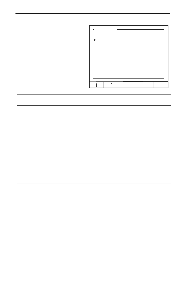
The Flow Meter menu is used to
configure a flow meter pulse input. All
pulse input screens offer the same
options as described in this section.
Options are configured individually for
each pulse input.
To access Flow Meter menu: Select a
Flow Meter input from the Inputs
window in the main setup menu.
To enter parameters in this menu, use
EDIT key, then use arrow keys to
modify the entries. Press SAVE when
complete.
Display Parameters
Instruction Manual
low Meter: 1
State:
Channel ID: Flow: 1 ENABLED
K Factor: 1000.00 pls / GAL
Max Value: 50.00 GPM
K-Fac Fmt: 9999.99 GPM
Rate Fmt: 9999.99 GPM
Total Fmt: 9999.99 GAL
Units: GAL & GPM
Display: RATE
EDIT EXIT
Channel ID
Enter a name for the channel, which appears on the operation screens,
and wherever else the channel is referenced.
Max Value
Specify the rate or total maximum. When this level is reached, the
channel's bargraph will appear completely filled.
Rate Fmt:
Select a position for the rate display decimal point by shifting left or right
(zero to five places.)
Total Fmt
Select a position for the total display decimal point by shifting left or
right (zero to five places.)
Units
Display
Select from any available unit combinations for flow.
Set to display [RATE] or [TOTAL] based bargraphs during operation.
This entry also determines whether assigned relay actions (other than
Trigger Relay) are linked to rate or total values. The picture on page 43
shows a typical screen when set to display total.
Input Configuration Parameters
State
K Factor
K-Fac Fmt
Enable or disable the input by selecting [ENABLED] or [OFF]. If a
certain flow meter input is not going to be used, [OFF] must be
selected.
Specify the conversion factor "K" in pulses per unit.
Select a position for the K Factor decimal point by shifting left or right
(zero to five places.)
30
Page 31

ConsoliDator Multi-Channel Controlle
r
Instruction Manual
Programming Relays
Each relay has an Alarm Setup menu used to program its functions. Functions are
programmed individually for each relay except in the case of Lead-Lag mode. Each relay
has the same available functions. All relays may be manually overridden. Before the relays
are set up, verify that the inputs have been configured.
To access Alarm Setup menu: Select a relay from the Relays window in the main setup
menu.
Use Alarm Mode setting to assign relay action. When a mode is selected, relay menu
options change accordingly. If the relay will not be used, [OFF] should be selected.
Supervisory or Summary Alarm Modes
Select [Supervisory Alarm] from Alarm Mode options to turn relay on (energize) when a
CPU failure is detected or if a process input is lost (no signal present.)
Select [Summary Alarm] from Alarm Mode options to turn relay on when any other relay
enters alarm state.
High or Low Alarm Modes
Alarm Setup: 1
High or Low functions are used to
turn the relay on and off at selected
process points. If it is necessary to
have an external reset using a
digital input channel or the ACK key
select Annunciator High or Low
Alarm Modes instead.
Select [HIGH] from Alarm Mode
options to turn relay on (energize)
when high set point is reached and
off when low reset point is reached.
Select [LOW] from Alarm Mode
options to turn relay on when low
set point is reached and off when
high reset point is reached.
Channel
High Value
Low Value
Delay ON
Assign the relay to any analog or pulse input.
Enter high process variable set/reset point.
Enter low process variable set/reset point.
Enter the delay between when the set point is reached and the
relay turns on (energizes.)
Delay OFF
Enter the delay between when the reset point is reached and the
relay turns off (de-energizes.)
Alarm Mode: HIGH
Channel: [1] Analog: 1
High Value: 16.00 mA
Low Value: 8.00 mA
Delay ON: 1.0 sec
Delay OFF: 0.5 sec
EDIT EXIT
31
Page 32

ConsoliDator Multi-Channel Controlle
r
Multi-Channel High or Low
Alarm Modes
Multi-Channel High or Low modes
are used as an alarm triggered by a
set point common to the linked
channels.
Select [HIGH: Multi-Chan] from
Alarm Mode options to turn relay on
(energize) when high set point is
reached by any linked channel, and
off when all linked channels are
below reset point.
Select [Low: Multi-Chan] from Alarm
Mode options to turn relay on
(energize) when low set point is
reached by any linked channel, and
off when all linked channels are
above reset point.
Channel
High Value
Low Value
Delay ON
Delay OFF
Link Channels
Assign the relay to any analog or pulse input.
Enter high process variable set/reset point.
Enter low process variable set/reset point.
Enter the delay between when the set point is reached and the
relay turns on (energizes.)
Enter the delay between when the reset point is reached and the
relay turns off (de-energizes.)
Select the channels to link .
Instruction Manual
Alarm Setup: 1
Alarm Mode: HIGH: Multi-Chan
High Value: 160.0 GAL
Low Value: 8.0 GAL
Delay ON: 1.0 sec
Delay OFF: 0.5 sec
Link Channels:
1 2 3 4 5 6 7 8
ON:
EDIT EXIT
32
Page 33
ConsoliDator Multi-Channel Controlle
r
High or Low Pulse Alarm
Modes
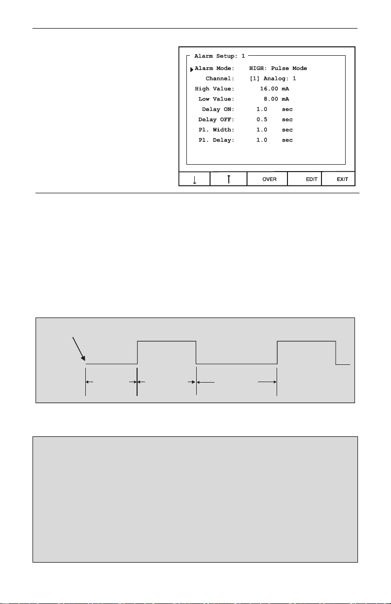
Pulse Modes are used to generate
an on/off continuous pulsing signal.
Select [HIGH: Pulse Mode] from
Alarm Mode options to continuously
pulse relay when high set point is
reached. Pulsing stops when low
reset point is reached.
Select [LOW: Pulse Mode] from
Alarm Mode options to continuously
pulse relay when low set point is
reached. Pulsing stops when high
reset point is reached.
High Value
Low Value
Delay ON
Delay OFF
Pl. Width
Pl. Delay
Over
Enter high process variable set/reset point.
Enter low process variable set/reset point.
Enter a delay between when the set point is reached and the pulse
signal starts.
Enter a delay between when the reset point is reached and the
pulse signal stops.
Enter pulse duration (Energized relay.)
Enter duration between pulses (De-energized relay.)
Enter override menu to override the channel alarm settings.
Instruction Manual
Set Point Reached
Delay ON
Pulse Width
Pulse Delay
Figure 20. Pulse Relay Timing Diagram
Example Pulse Mode Scenario
The unit is set to the following:
Alarm Mode: [HIGH: Pulse Mode]
High Value: [16 mA]
Low Value: [10 mA]
Delay ON: [2 sec]
Delay OFF: [3 sec]
Pl. Width: [1 sec]
Pl. Delay: [2.5 sec]
The following describes operation based on the above settings:
The process reaches 16 mA: 2 seconds pass with no relay action.
Relay begins pulsing: on for 1 second, off for 2.5 seconds. ON-OFF alternation continues while the
process is above 10 mA. The process reaches 10 mA: Pulse sequence continues for 3 seconds and
then stops completely until 16 mA is reached again.
33
Page 34
ConsoliDator Multi-Channel Controlle
r
Trigger Alarm Mode
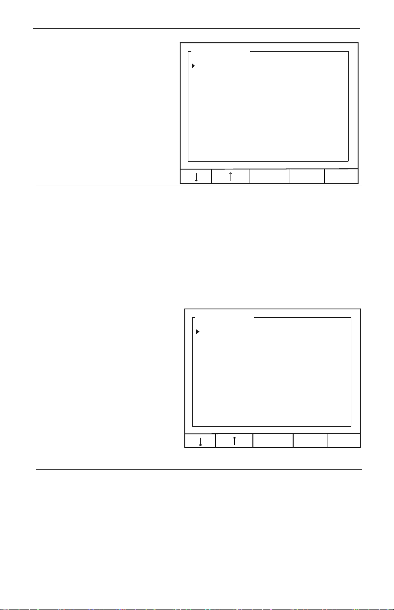
Select Trigger mode to pulse the
relay once each time the total from
a flow meter pulse input channel is
incremented by a certain value.
Instruction Manual
Alarm Setup: 1
Alarm Mode: Trigger
Channel: [A] Flow: 1
Set Point: 10.00 G AL
Pl Width: 1.0 sec
EDIT EXIT
Channel
Set Point
Assign the relay to any flow meter pulse input.
Enter process variable set point. Each time the total increases by
this value, the relay will be pulsed one time.
Pl. Width
Enter duration for the relay to pulse on (energize.)
Annunciator High or Low
Alarm Modes
The Annunciator functions are similar
to High and Low Alarm Modes except
for the addition of a reset capability
from the ACK key, a digital input
channel (normally open pushbutton
switch), or External Key 4.
Select [ANNUNCIATOR: HIGH] from
Alarm Mode options to turn relay on
(energize) when high set point is
reached and off when low reset point
is reached.
Select [ANNUNCIATOR: LOW] from
Alarm Mode options to turn relay on
when low set point is reached and off
when high reset point is reached.
Channel
High Value
Low Value
Delay ON
Delay OFF
Reset Ch
Assign the relay to any analog or pulse input.
Enter high process variable set/reset point.
Enter low process variable set/reset point.
Enter the delay between when the set point is reached and the
relay turns on (energizes.)
Enter the delay between when the reset point is reached and the
relay turns off (de-energizes.)
Select a digital input channel to be used to reset the relay.
Alarm Setup: 1
Alarm Mode: ANNUNCIATOR: HIGH
Channel: [A] Flow: 1
High Value: 16.00 GPM
Low Value: 8.00 GPM
Delay ON: 1.0 sec
Delay OFF: 0.5 sec
Reset Ch: [1] Reed SW: 1
34
EDIT EXIT
Page 35
ConsoliDator Multi-Channel Controlle
r
Plunger Lift by Differential
Pressure Mode
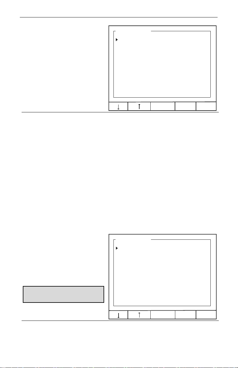
Select [PLUNGER LIFT: DP] from
Alarm Mode options to operate a
plunger lift system that monitors
differential pressure.
Instruction Manual
Alarm Setup: 1
Alarm Mode: PLUNGER LIFT: DP
Tubing Ch: [A] Flow: 1
Casing Ch: [2] Analog: 2
Switch Ch: [1] Reed SW: 1
Set Point: 100.00 GPM
Delay ON: 1.0 sec
After Flow: 5 min
EDIT EXIT
Tubing Ch
Select a 4-20 mA input or pulse input (flow) as the tubing pressure
or flow rate.
Casing Ch
Select a 4-20 mA input or pulse input (flow) as the casing pressure
or flow rate.
Switch Ch
Set Point
Select the channel that monitors a (pressure) switch input.
Enter the process variable point at which the relay closes a valve.
The point may either be differential pressure or flow from a turbine
meter.
Delay On
Enter the time between when the set point is reached and the
relay turns on (energizes.)
After Flow
Enter a time long enough to guarantee that the plunger will fall to
the bottom of the well.
Plunger Lift by Time Mode
Select [PLUNGER LIFT: TIME] from
Alarm Mode options to operate a
plunger lift system based on time by
specifying the on and off durations
in the cycle.
This mode may also be used as a
general timer to cycle the relay on and
off.
Alarm Setup: 1
Alarm Mode: PLUNGER LIFT: TIME
Rly On/Off: OFF
Time ON: 1.0 min
Time OFF: 5.0 min
Relay On/Off
TIME ON:
TIME OFF
EDIT EXIT
Select [ON] to enable relay function or [OFF] to disable.
Enter relay-on duration.
Enter relay-off duration.
35
Page 36
ConsoliDator Multi-Channel Controlle
r
Lead-Lag Modes
(Pump Alternation Control)
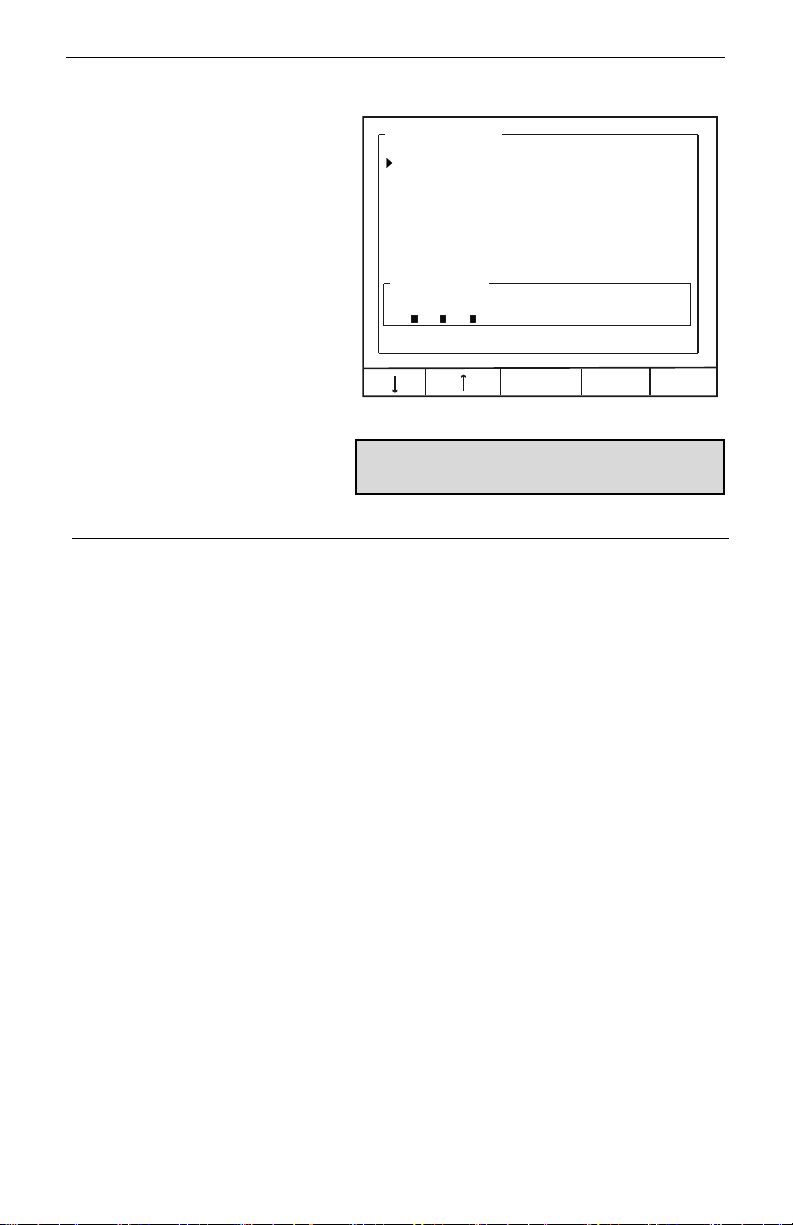
Lead-Lag modes are used to
operate up to 9 relays in sequence.
This mode is commonly used for
pump alternation control. For
example: If relays #1, #2, and #3
are linked in this menu, relay #1
turns on the first time the set point is
reached and off when the reset
point is reached, relay #2 cycles the
second time, and relay #3 cycles
the third time. The sequence then
repeats beginning with relay #1.
Select [LEAD-LAG: HIGH] from
Alarm Mode options to turn relay on
when high set point is reached and
off when low reset point is reached.
Select [LEAD-LAG: LOW] from
Alarm Mode options to turn relay on
when low set point is reached and
off when high reset point is reached.
Channel
High Value
Low Value
Delay ON
Assign the relay to any analog or pulse input.
Enter high process variable set/reset point.
Enter low process variable set/reset point.
Enter the delay between when the set point is reached and the
relay turns on (energizes.)
Delay OFF
Enter the delay between when the reset point is reached and the
relay turns off (de-energizes.)
Link Relays
Select between two and nine relays to operate in sequence.
Note: Linked relays must be set to [OFF] in their
respective menus. (i.e. If Alarm Setup 1 links Relay #2,
Alarm Setup 2 must read "Alarm Mode: [OFF]")
Instruction Manual
Alarm Setup: 1
Alarm Mode: LEAD-LAG: HIGH
Channel: TANK 1
High Value: 160.0 GAL
Low Value: 8.0 GAL
Delay ON: 1.0 sec
Delay OFF: 0.5 sec
Link Relays:
1 2 3 4 5 6 7 8 9
ON:
OVER
EDIT EXIT
36
Page 37

ConsoliDator Multi-Channel Controlle
r
O
Lead-Lag Override Function
Lead-Lag mode supports an
override function, which allows up to
five linked relays to turn on if
programmed points are reached.
Override set points also operate in
sequence. They are not assigned to
particular relays.
Use OVER key in Lead-Lag menu
to access override menu.
Over Type
Set Pt. #1 (#2, #3, #4)
Choose number relays to override main relay (Up to 4 additional
set points for a maximum of 5 relays operating at once.)
Specify each process set point for the override relays to
activate.
Instruction Manual
Lead-Lag Override: 1
ver Type: Override 1 & 2 ON
Set Pt. #1: 170.0 GAL
Set Pt. #2: 180.0 GAL
EDIT EXIT
Example:
[LEAD-LAG: HIGH] is used to link relays #1, #2, and #3. In the Alarm Menu, High Value is set at 160.0
GAL and Low Value is set at 8.0 GAL. In the Override Menu, Over Type is set to [Override 1 & 2 ON.]
Set Pt. #1 is set to 170.0 GAL and Set Pt. #2 is set to 180.0 GAL.
When the input reaches 160.0 GAL, the first relay in the sequence (Relay #1) turns on. When 170.0 GAL
is reached, the next relay (Relay #2) turns on. If at this point the input decreases and drops below 8.00
GAL, both relays will turn OFF simultaneously. If instead, the input reaches 180.0 GAL, the third relay
will turn ON and all three will remain ON until 8.0 GAL has been reached.
Note: In most override applications the number of relays linked should equal the total number of set
points. However, linking additional relays is allowed. In the example, if 5 relays were linked and the total
set points remained at 3, it would only be possible for 3 of the 5 to be on at once, but all 5 would
sequence.
37
Page 38
ConsoliDator Multi-Channel Controlle
r
Instruction Manual
Linear Pulse Width
Modulation Mode
Alarm Setup: 1
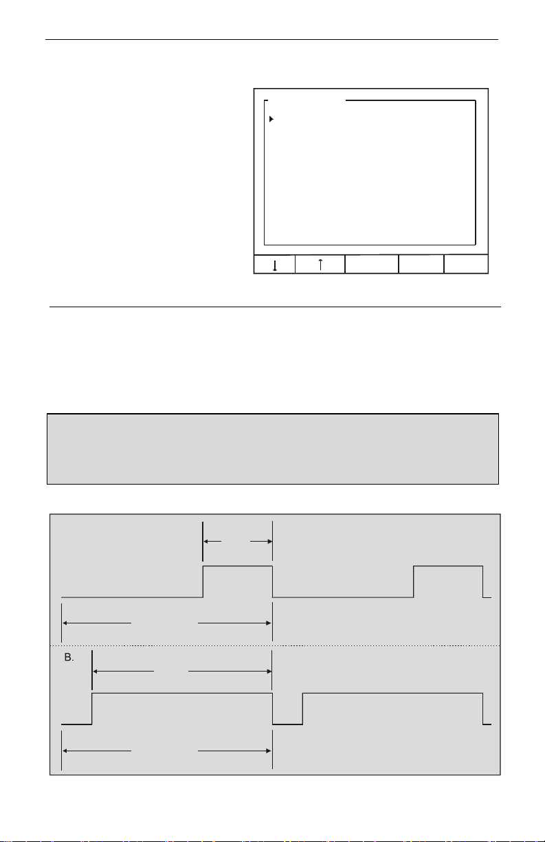
Linear PWM Mode is used to create
an on/off pulse signal with a
modulated duty cycle. In this mode
the percentage of the relay cycle in
which the relay is in the on state
varies with relation to the process
value.
See Figure 21 for an example
showing that the cycle time (period)
remains the same, but the relay-on
percentage of the cycle changes
with the process value.
Select [PWM: Linear] from Alarm
Mode options to modulate the pulse
relay signal in linear mode.
Channel
100% Value
Assign the relay to any analog or pulse input.
Enter the process value at which the pulse width will be 100% of
cycle.
0% Value
Enter the process value at which the pulse width will be 0% of
cycle.
Cycle Time
Note 1: Due to the life expectancy of mechanical relays, it is strongly recommended that cycle times be
as long as possible (many minutes.) Using a cycle time of less than a few minutes can wear out a relay
and cause faulty operation.
Note 2: Relay is a constant OFF when process variable is at or below 10% of full span and a constant
ON when process variable is at or above 90% of full span to prevent abrupt switching from occurring and
causing damage to relays.
Enter the period for 1 cycle (maximum 6550 sec.)
Alarm Mode: PWM: Linear
Channel: [A] Flow: 1
100% Value: 16.00 GPM
0% Value: 8.00 GPM
Cycle Time: 600 sec
EDIT EXIT
A.
33 %
Relay output when process variable
reaches 33% of the span specified by
and
0% Value 100% Value
Cycle Time
Relay output when process variable
85 %
reaches 85% of the span specified by
and
0% Value 100% Value
Cycle Time
Figure 21. Linear PWM Relay Timing Example
38
Page 39
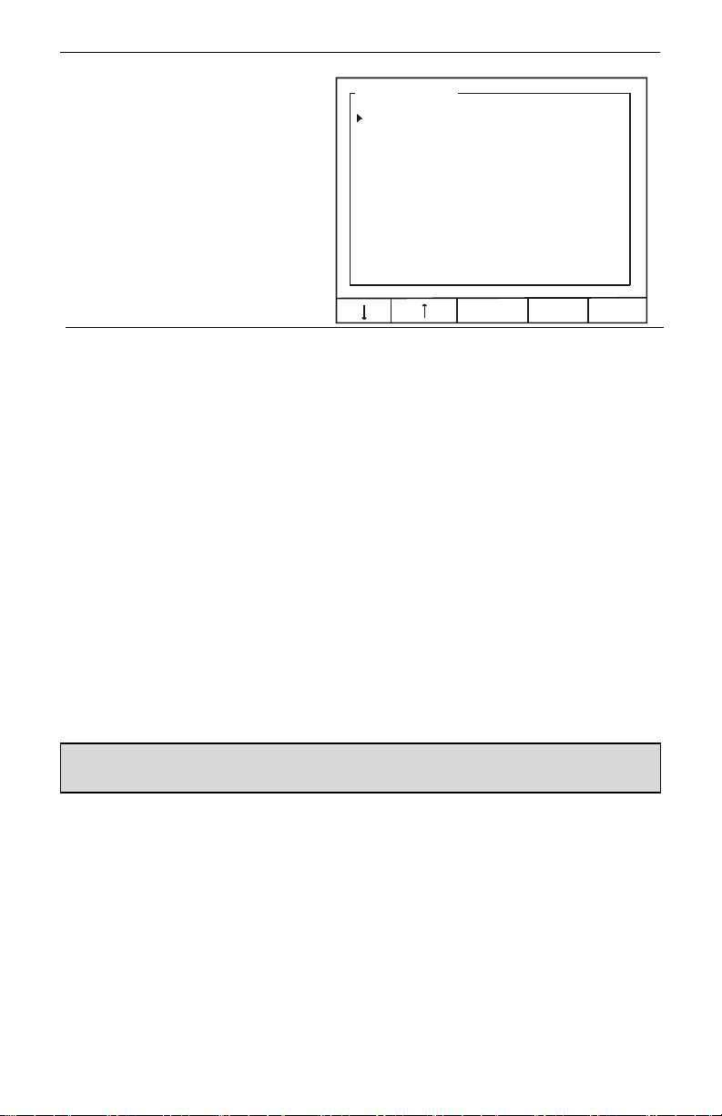
ConsoliDator Multi-Channel Controlle
r
Proportional Plus Integral
Pulse Width Modulation Mode
PWM PI Control Mode is used to
create an on/off pulse signal with a
duty cycle modulated by the
proportional integral settings. In this
mode the percentage of the relay
cycle in which the relay is in the on
state varies with relation to the
process value feedback and the PI
settings.
Set Point
Feedbk Ch
Prop. Gain
Int. Time
Cycle Time
Rly Period
Int. Limit
Inc / Dec
Enter the process target.
Select an analog input to supply the feedback signal from the
system.
Enter the proportional gain expressed as a percentage.
Enter the integral time expressed as seconds per repeat.
Enter the PI calculation cycle time (Low number for fastresponding systems, high number for slow-responding
systems.)
Enter a relay period.
Specify the integration limit as a percentage (Limits integral
influence on the output.)
Select either [Increasing] or [Decreasing].
Instruction Manual
Alarm Setup: 1
Alarm Mode: PWM: PI Control
Feedbk Ch: [A] Flow: 1
Set Point: 12.00 GPM
Prop. Gain: 32.0 %
Int. Time: 0.1 sec / rpt
Cycle Time: 1 sec
Rly Period: 600 sec
Int. Limit: 1.0 %
Inc / Dec: Increasing
EDIT EXIT
Note: Due to the life expectancy of mechanical relays, it is strongly recommended that cycle times be as
long as possible (many minutes.) Using a cycle time of less than a few minutes can wear out a relay and
cause faulty operation.
39
Page 40
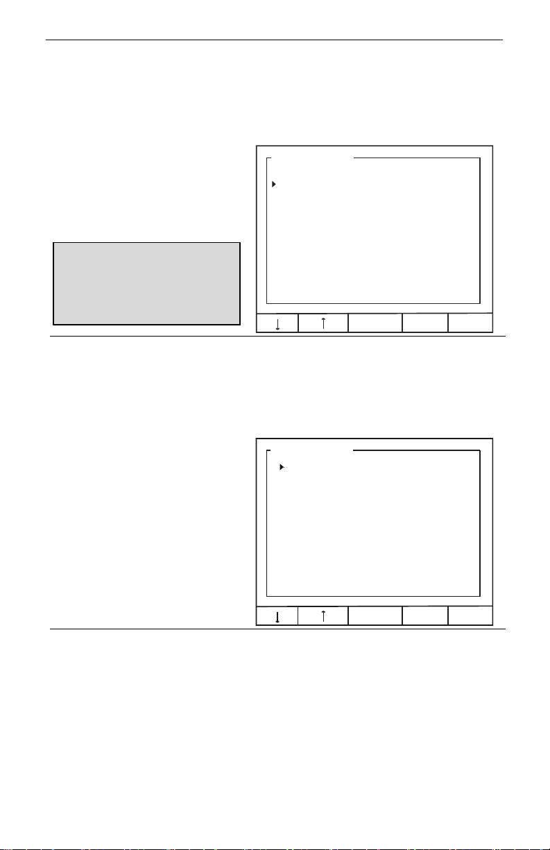
ConsoliDator Multi-Channel Controlle
r
Instruction Manual
Setting 4-20 mA Outputs
The Analog Output menu is used to configure the 4-20 mA outputs. Each output has a
separate screen. All 4-20 mA outputs can be configured using the information provided in
this section.
Linear Scaling of 4-20 mA
Output
Select [LINEAR] from Mode options
to set the analog output for a linear
scale from 4 to 20 mA.
Example: If 4 mA Val is set to 10 gal and
20 mA Val is set to 30 gal, when the
input reads 10 gal, 4 mA will be
transmitted out. When the input reads 20
gal, 12 mA will be transmitted out, and
when the input reads 30 gal, 20 mA will
be transmitted out.
Input Ch
Assign the output to any 4-20 mA or pulse input. Note that more than
one output can be scaled from the same input by simply choosing that
channel in another Analog Output.
4 mA Val
20 mA Val
Enter the low process level that will result in a 4 mA signal transmission.
Enter the high process level that will result a 20 mA signal transmission.
PID Control Using 4-20 mA
Output
To set the analog output for PID
control, select [PID CONTROL]
from Mode options.
Analog Output: 1
Mode: LINEAR
Input Ch: [1] Analog: 1
4 mA Val: 10 gal
20 mA Val: 30 gal
Analog Output: 1
Mode: PID CONTROL
Set-point: 8.00 mA
Feedbk Ch: [1] Analog: 1
Prop. Gain: 32.0 %
Int. Time: 0.1 sec / rpt
Deri. Time: 0.0 sec
Cycle Time: 1.0 sec
Int. Limit: 1.0 %
Inc / Dec: Increasing
EDIT EXIT
Set Point
Feedbk Ch
Prop. Gain
Int. Time
Deri. Time
Cycle Time
Int. Limit
Inc / Dec
Enter the process target.
Select an analog input to supply the feedback signal from the system.
Enter the proportional gain expressed as a percentage.
Enter the integral time expressed as seconds per repeat.
Enter the derivative time in seconds.
Enter the PID calculation cycle time (Low number for fast-responding
systems, high number for slow-responding systems.)
Specify the integration limit as percentage (Limits integral influence on
the output.)
Select either [Increasing] or [Decreasing].
40
EDIT EXIT
Page 41

ConsoliDator Multi-Channel Controlle
r
R
R
R
R
R
R
R
R
R
R
Instruction Manual
OPERATION
Viewing Screens
The instrument displays various screens with bargraphs, numerical values, and relay status
throughout operation. There are two basic modes of operation: Automatic, which allows the
controller to function based on it’s programmed settings; and Manual mode, which disables
all automatic output functions. The controller initializes in Automatic mode. When manual
mode is entered, all outputs are suspended or frozen in their current state so that they can
only be changed manually. Although, totalization continues while in Manual mode. The
example screens that follow can be viewed in all modes of operation with only subtle
differences noticeable including button names and headings.
Relay Status Screen
To the right is an example of a
Relay Status screen as it would
appear in Automatic mode. The
screen displays the current state of
the relay, the total time the relay
has spent in the ON state and how
many times the relay has cycled
from OFF to ON. In Manual mode,
this screen allows for overriding the
relays and resetting the Hours and
Cycles counts. This is discussed
further in Manual Relay Control
(page 45.)
SETUP Press to enter setup menu (Password restricted).
AUTO / MANUAL The AUTO key indicates the unit is in Automatic mode. Press it to
switch to Manual mode. Press NEXT to return to main screen. Once
in Manual mode press MANUAL to switch to Automatic mode.
Note: The AUTO / MANUAL modes are password restricted.
ACK Press to acknowledge (reset) the relays assigned to Supervisory,
Summary or Annunciator Alarm functions and to silence the buzzer.
NEXT Press to scroll to the next operation screen.
elay Status:
Hours Cycles
elay #1: ON 10.2 320
elay #2: OFF 215.0 566
elay #3: OFF 197.6 512
elay #4: ON 175.2 490
elay #5: OFF 121.7 251
elay #6: OFF 255.1 357
elay #7: ON 11.7 22
elay #8: ON 143.6 30
elay #9: OFF 412.5 197
ACK NEXTSETUP AUTO
41
Page 42
ConsoliDator Multi-Channel Controlle
r
R
2
3
Instruction Manual
Multiple Channel Operation
Screen
Ch1 Ch2 Ch3 Ch4
To the right is an example of a
multiple channel operation screen
for a four input application. The
screen reflects all of the inputs that
were detected or enabled during
setup. Depending on the actual
number of inputs in use, this screen
will adjust its size and proportions
automatically.
Note: It is recommended not to exceed 8
channels or graphics may overlap.
SETUP AUTO ACK NEXT
SETUP Press to enter setup menu (Password restricted).
AUTO / MANUAL The AUTO key indicates the unit is in Automatic mode. Press it to
switch to Manual mode. Press NEXT to return to main screen. Once
in Manual mode press MANUAL to switch to Automatic mode.
Note: The AUTO / MANUAL modes are password restricted.
ACK Press to acknowledge (reset) the relays assigned to Supervisory,
Summary or Annunciator Alarm functions and to silence the buzzer.
NEXT Press to scroll to the next operation screen.
100 ft
Single Analog Input
Operation Screen
For each analog input channel,
there is a detailed individual
channel operation screen, which
shows a bargraph with relay set
points, numerical values, sensor
input, and relay status for the relays
assigned to that particular channel.
0 ft
SETUP AUTO ACK NEXTSIM
SETUP Press to enter setup menu (Password restricted).
AUTO / MANUAL The AUTO key indicates the unit is in Automatic mode. Press it to
switch to Manual mode. Press NEXT to return to main screen. Once
in Manual mode press MANUAL to switch to Automatic mode.
Note: The AUTO / MANUAL modes are password restricted.
SIM / RST Press to enter a simulation mode where the input can be adjusted
manually. (Password restricted.) If the channel is set for Integration
totalizing, the SIM key is replaced by RST, which is used to reset
the total to zero (Password restricted.)
ACK Press to acknowledge (reset) the relays assigned to Supervisory,
Summary or Annunciator Alarm functions and to silence the buzzer.
NEXT Press to scroll to the next operation screen.
H2
L2
H3
L3
Ch 1:
12.000
Ch 2:
13.000
Ch 3:
14.000
Ch 4:
15.000
Ch 1:
87.5
Sensor In: 18.00 mA
ly: Low: High:
: 40.0 50.0 ON
: 8.0 20.0 ON
mA
mA
mA
mA
mA
ft
42
Page 43
ConsoliDator Multi-Channel Controlle
r
R
2
O
O
O
Instruction Manual
Single Flow Meter Pulse Input
Operation Screen
For each flow meter pulse input
channel, there is a detailed
individual channel operation screen,
which shows a bargraph with relay
set points, numerical values for rate
and total, and relay status for the
relays assigned to that particular
channel. This screen may also be
set to show a bargraph for rate
rather than total. See Setting Flow
Meter Pulse Inputs (page 30.)
SETUP Press to enter setup menu (Password restricted).
AUTO / MANUAL The AUTO key indicates the unit is in Automatic mode. Press it to
switch to Manual mode. Press NEXT to return to main screen. Once
in Manual mode press MANUAL to switch to Automatic mode.
Note: The AUTO / MANUAL modes are password restricted.
RST Use this key to reset the total to zero (Password restricted.)
ACK Use to acknowledge (reset) the relays assigned to Supervisory,
Summary or Annunciator Alarm functions and to silence the buzzer.
NEXT Use this key to scroll to the next operation screen.
500 GAL
H2
L2
0 GAL
SETUP AUTO ACK NEXTRST
Rate: 220.00 GPH
ly: Low: High:
: 40.0 50.0 ON
Flow: 1
300.0
GAL
Digital Inputs
Digital Input Operation
Screen
The Digital Input screen shows the
states of the digital inputs. ON is
Reed SW: 1 ON
Reed SW: 2
N
shown when a switch connected to
the input is closed or when an open
Reed SW: 3
N
collector transistor is conducting.
OFF is shown when the switch is
open or when the open collector
Reed SW: 4
N
transistor is not conducting.
AUTOSETUP
ACK NEXT
SETUP Press to enter setup menu (Password restricted).
AUTO / MANUAL The AUTO key indicates the unit is in Automatic mode. Press it to
switch to Manual mode. Press NEXT to return to main screen. Once
in Manual mode press MANUAL to switch to Automatic mode.
Note: The AUTO / MANUAL modes are password restricted.
ACK Use to acknowledge (reset) the relays assigned to Supervisory,
Summary or Annunciator Alarm functions and to silence the buzzer.
NEXT Use this key to scroll to the next operation screen.
43
Page 44
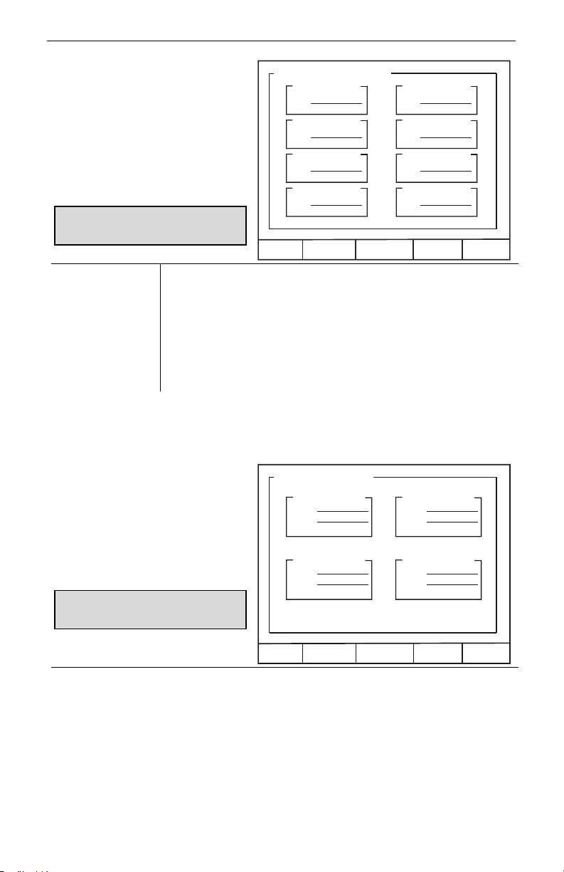
ConsoliDator Multi-Channel Controlle
r
T
T
Instruction Manual
Analog Input Numeric Screen
To the right is an example of an
analog numeric summary screen for
an eight input application. It shows
a box for each channel with the
sensor input in mA on the bottom
and the scaled engineering units on
top. The screen reflects all of the
inputs that were detected.
Note: The total is displayed as the
engineering value when that channel is
set for Integration mode.
SETUP Press to enter setup menu (Password restricted).
AUTO / MANUAL The AUTO key indicates the unit is in Automatic mode. Press it to
switch to Manual mode. Press NEXT to return to main screen. Once
in Manual mode press MANUAL to switch to Automatic mode.
Note: The AUTO / MANUAL modes are password restricted.
ACK Press to acknowledge (reset) the relays assigned to Supervisory,
Summary or Annunciator Alarm functions and to silence the buzzer.
NEXT Press to scroll to the next operation screen.
Analog Sensor Inputs:
Tank 1
50.000 ft
16.00 mA
Tank 3
30.000 ft
8.00 mA
Tank 5
50.000 ft
16.00 mA
Tank 7
30.000 ft
8.00 mA
SETUP AUTO A CK NEXT
Tank 2
40.000 ft
12.00 mA
Tank 4
20.000 ft
12.00 mA
ank 6
40.000 ft
12.00 mA
ank 8
20.000 ft
12.00 mA
Flowmeter Inputs:
Flow Meter Numeric Screen
To the right is an example of a flow
meter numeric summary screen. It
System 1
100.00 GPM
800.00 GAL
200.00 Hz
Backup 1
0.00 GPM
0.00 GAL
0.00 Hz
shows a box for each flow channel
with the input frequency, flow and
total.
Note: The total is displayed as the
engineering value when that channel is
set for Integration mode.
System 2
150.00 GPM
500.00 GAL
300.00 Hz
SETUP AUTO ACK NEXT
Backup 2
0.00 GPM
0.00 GAL
0.00 Hz
SETUP Press to enter setup menu (Password restricted).
AUTO / MANUAL The AUTO key indicates the unit is in Automatic mode. Press it to
switch to Manual mode. Press NEXT to return to main screen. Once
in Manual mode press MANUAL to switch to Automatic mode.
Note: The AUTO / MANUAL modes are password restricted.
ACK Press to acknowledge (reset) the relays assigned to Supervisory,
Summary or Annunciator Alarm functions and to silence the buzzer.
NEXT Press to scroll to the next operation screen.
44
Page 45
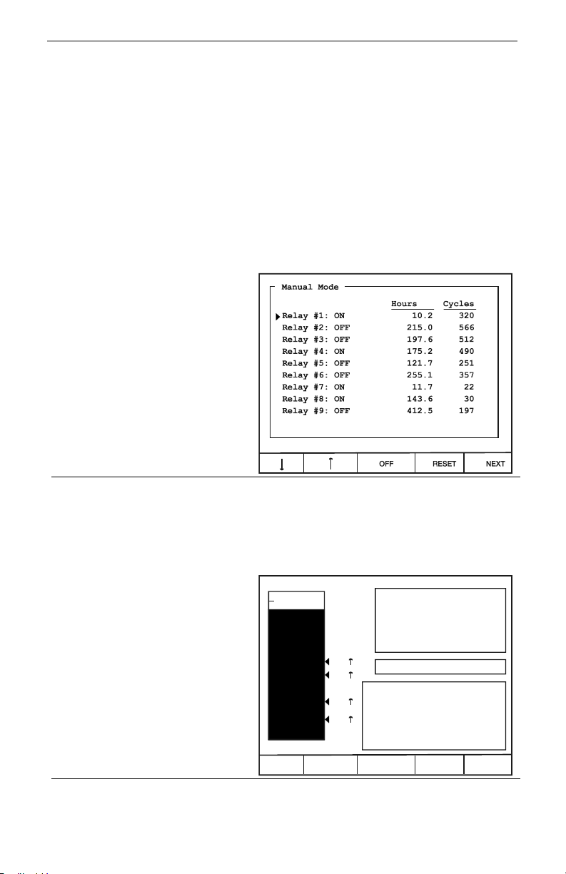
ConsoliDator Multi-Channel Controlle
r
R
2
3
Instruction Manual
Manual and Simulation Modes
When manual mode is entered, all outputs are suspended or frozen in their current state
until they are changed manually, although totalization continues while in Manual mode.
For example: Relay #1 is programmed to activate a pump based on the level of
Channel #1. If the activation level is reached, and the pump is turned on, it will remain
active through the transition from Automatic to Manual. In Manual mode, the relay will not
respond to changes in the Channel #1 level even if it goes below a programmed
reset point. The operator has complete control over each relay’s state and must turn Relay
#1 off by doing so in the Manual Relay Control Screen (shown below on this page.)
Accordingly, when transitioning from Manual to Automatic Mode, the controller scans the
inputs and updates output status ignoring changes to relay status while in Manual mode.
However, if the setup and programming of the controller was modified during Manual mode,
these changes take effect the moment the controller re-enters Automatic mode. You may
choose to disable outputs while reprogramming by entering Manual mode.
Manual Relay Control
To the right is an example of a
Manual Relay Control screen as it
appears in Manual mode. The
screen displays the current state of
the relay, the total time the relay
has spent in the ON state and how
many times the relay has cycled
from OFF to ON. In Manual mode,
this screen allows for overriding the
relays and resetting the Hours and
Cycles counts.
,
ON / OFF Press to turn selected relay on or off.
RESET Press to reset Hours and Cycles counts for selected relay.
NEXT/EXIT Press to scroll to the next operation screen.
Simulation Mode
To the right is an example of an
analog input Simulation screen.
Simulation is accessible to each
analog input individually.
Simulation mode may be accessed
while operating in Automatic mode
or Manual mode. When in
Automatic mode, all outputs
respond to the simulation as
programmed for normal operation.
During Manual mode, changing the
settings has no effect on outputs.
+, -
EXIT Press to exit Simulation mode.
Move cursor up or down one relay.
100 ft
H2
L2
H3
L3
0 ft
+- EXIT
Increase or decrease level.
Ch 1:
87.5
Sensor In: 18.00 mA
ly: Low: High:
: 40.0 50.0 ON
: 8.0 20.0 ON
ft
45
Page 46
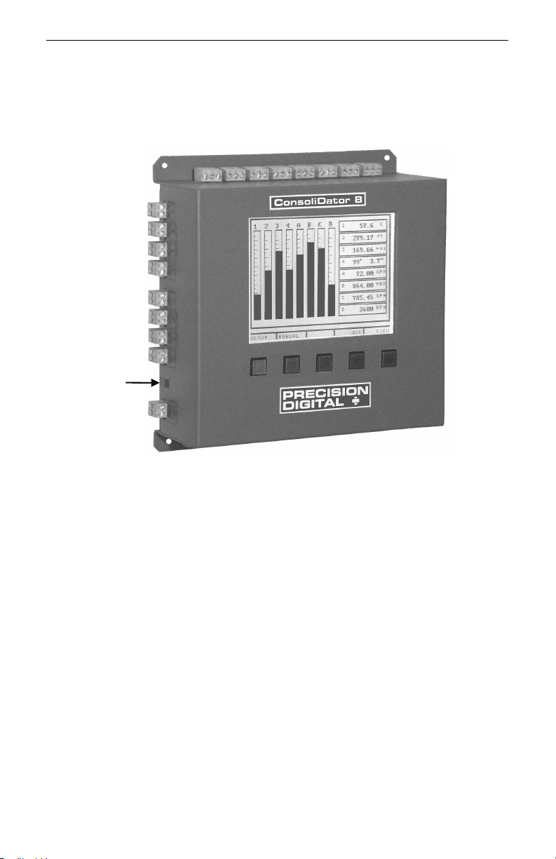
ConsoliDator Multi-Channel Controlle
r
Instruction Manual
Contrast Adjustment Control
All ConsoliDators are adjusted at the factory for optimal viewing. If additional adjustment is
needed, use the contrast adjustment potentiometer located on the left side of the case, next
to the DC POWER connector.
Contrast
Adjust
Control
46
Page 47
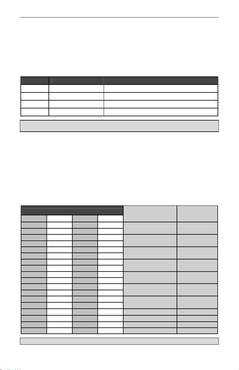
ConsoliDator Multi-Channel Controlle
r
Instruction Manual
MODBUS® SERIAL COMMUNICATION
The controller is equipped with serial communication capability as a standard feature. Baud
Rate, Parity, Modbus ID (Address) and Transmit Delay are entered in the General
Functions box, which appears in the main setup menu. The baud rate and parity selected
must match the settings for all other devices on the network. Modbus ID must be unique so
it will not interfere with other devices.
ConsoliDators support the following Modbus control functions:
Command Name Description
03 Read Holding Register Read multiple bytes from holding registers.
05 Write Single Coil Set single coil value control
06 Write Single Register Set single value into specified holding register.
16 Write Multiple Registers Set multiple values into specified holding registers.
Note: To save data to non-volatile memory after changing the contents of holding register(s) use the
Write Single Coil command [command code 05] to “ON” at address 64251.
To control the relays via MODBUS you would use the Write Single Coil command
[command code 05] and send either the “ON” or “OFF” to the appropriate alarm relay (1-9).
The ConsoliDator can also work as a "MODBUS Display" by setting the desired analog
input channel to the "FIXED" type and then over MODBUS change the "K-Factor/Modbus
Display" value for the corresponding channel. This input type is transparent to the rest of
the functions of the unit (i.e. relays, etc...). The value, once the EEPROM save command is
sent to the unit, is also maintained in EEPROM after the next power cycle.
Modbus Register Tables
Table 1. Analog Output Channels Register Addresses
Address (offset from 40000)
Description Data Type Ch. 1 Ch. 2 Ch. 3* Ch. 4*
801 819
802 820
803 821
804 822
805 823
806 824
807 825
808 826
809 827
810 828
811 829
812 830
813 831
814 832
815 833
816 834
817 835 853 871 Input Ch. Byte
818 836 854 872 PID Direction Byte
*Channels 3-4 only apply to ConsoliDator 4 (PD940 & PD941) models.
837 855
838 856
839 857
840 858
841 859
842 860
843 861
844 862
845 863
846 864
847 865
848 866
849 867
850 868
851 869
852 870
4 mA Value Floating Point
20 mA Value Floating Point
Set point Value Floating Point
PID KP Floating Point
PID KI Floating Point
PID KD Floating Point
PID Output Value Floating Point
PID Cycle Time Integer
Output Type Byte
47
Page 48
ConsoliDator Multi-Channel Controlle
r
Instruction Manual
Table 2. Analog Input Channels Register Addresses
Address (offset from 40000)
Description Data Type Ch. 1 Ch. 2 Ch. 3 Ch. 4 Ch. 5* Ch. 6* Ch. 7* Ch. 8*
1 33 65 97 129 161 193 225
2 34 66 98 130 162 194 226
3 35 67 99 131 163 195 227
4 36 68 100 132 164 196 228
5 37 69 101 133 165 197 229
6 38 70 102 134 166 198 230
7 39 71 103 135 167 199 231
8 40 72 104 136 168 200 232
9 41 73 105 137 169 201 233
10 42 74 106 138 170 202 234
11 43 75 107 139 171 203 235
12 44 76 108 140 172 204 236
13 45 77 109 141 173 205 237
14 46 78 110 142 174 206 238
15 47 79 111 143 175 207 239 Decimal Format Byte
16 48 80 112 144 176 208 240 Ch. Online Flag Byte
17 49 81 113 145 177 209 241 Ch. ID Char. 1 Byte
18 50 82 114 146 178 210 242 Ch. ID Char. 2 Byte
19 51 83 115 147 179 211 243 Ch. ID Char. 3 Byte
20 52 84 116 148 180 212 244 Ch. ID Char. 4 Byte
21 53 85 117 149 181 213 245 Ch. ID Char. 5 Byte
22 54 86 118 150 182 214 246 Ch. ID Char. 6 Byte
23 55 87 119 151 183 215 247 Ch. ID Char. 7 Byte
24 56 88 120 152 184 216 248 Ch. ID Char. 8 Byte
25 57 89 121 153 185 217 249 Ch. ID Char. 9 Byte
26 58 90 122 154 186 218 250 Ch. ID Char. 10 Byte
27 59 91 123 155 187 219 251 Units Character 1 Byte
28 60 92 124 156 188 220 252 Units Character 2 Byte
29 61 93 125 157 189 221 253 Units Character 3 Byte
1523 1547 1571 1595 1619 1643 1667 1691 Function Mode** Byte
1901 1911 1921 1931 1941 1951 1961 1971
1902 1912 1922 1932 1942 1952 1962 1972
1903 1913 1923 1933 1943 1953 1963 1973
1904 1914 1924 1934 1944 1954 1964 1974
1905 1915 1925 1935 1945 1955 1965 1975
1906 1916 1926 1936 1946 1956 1966 1976
1907 1917 1927 1937 1947 1957 1967 1977
1908 1918 1928 1938 1948 1958 1968 1978
1909 1919 1929 1939 1949 1959 1969 1979
1910 1920 1930 1940 1950 1960 1970 1980
*Channels 5-8 only apply to ConsoliDator 8 (PD980 & PD981) models.
Engineering Value Floating Point
Max. Graph Value Floating Point
Min. Graph Value Floating Point
High Value Floating Point
High Value mA Floating Point
Low Value Floating Point
Low Value mA Floating Point
K-Factor / Modbus
Display
Offset Floating Point
Conversion #1 Floating Point
Conversion #2 Floating Point
Channel Linking Byte
Function Channel Byte
Floating Point
**Function Mode Byte Values:
Byte = 0: Linear Byte = 16: Square Root Byte = 32: Difference
Byte = 48: Summation Byte = 64: Exponent Byte = 80: Multi-Point
Byte = 96: Fixed/Modbus Display Byte = 112: Integration – Sec Byte =128: Integration – Min
Byte = 144: Integration – Hour Byte =160: Integration – Day
48
Page 49
ConsoliDator Multi-Channel Controlle
r
Instruction Manual
Table 3. Flow Meter Pulse Input Channels Register Addresses
Address (offset from 40000)
Description Data Type Ch. 1 Ch. 2 Ch. 3 Ch. 4
261 291 321 351
262 292 322 352
263 293 323 353
264 294 324 354
265 295 325 355
266 296 326 356
267 297 327 357
268 298 328 358
269 299 329 359
270 300 330 360
271 301 331 361 Rate Decimal Format Byte
272 302 332 362
273 303 333 363 Ch. Online Flag Byte
274 304 334 364 Display Format (Rate or Total) Byte
275 305 335 365 Ch. ID Character 1 Byte
276 306 336 366 Ch. ID Character 2 Byte
277 307 337 367 Ch. ID Character 3 Byte
278 308 338 368 Ch. ID Character 4 Byte
279 309 339 369 Ch. ID Character 5 Byte
280 310 340 370 Ch. ID Character 6 Byte
281 311 341 371 Ch. ID Character 7 Byte
282 312 342 372 Ch. ID Character 8 Byte
283 313 343 373 Ch. ID Character 9 Byte
284 314 344 374 Ch. ID Character 10 Byte
285 315 345 375 Rate Units Character 1 Byte
286 316 346 376 Rate Units Character 2 Byte
287 317 347 377 Rate Units Character 3 Byte
288 318 348 378 Total Units Character 1 Byte
289 319 349 379 Total Units Character 2 Byte
290 320 350 380 Total Units Character 3 Byte
Table 4. Digital Input Channels Register Addresses
Address (offset from 40000)
401 413 425 437 Digital State Byte
402 414 426 438 Inversion State Byte
403 415 427 439 Ch. ID Character 1 Byte
404 416 428 440 Ch. ID Character 2 Byte
405 417 429 441 Ch. ID Character 3 Byte
406 418 430 442 Ch. ID Character 4 Byte
407 419 431 443 Ch. ID Character 5 Byte
408 420 432 444 Ch. ID Character 6 Byte
409 421 433 445 Ch. ID Character 7 Byte
410 422 434 446 Ch. ID Character 8 Byte
411 423 435 447 Ch. ID Character 9 Byte
412 424 436 448 Ch. ID Character 10 Byte
Flow Meter Rate Floating Point
Flow Meter Total Floating Point
K Factor Floating Point
Maximum Graph Value Floating Point
Flow Meter Previous Total Floating Point
Total Decimal Format – Upper 4 bits
K Factor Decimal Format – Lower 4 bits
Description Data Type Ch. 1 Ch. 2 Ch. 3 Ch. 4
Byte
49
Page 50
ConsoliDator Multi-Channel Controlle
r
Instruction Manual
Table 5. Relay Channels Register Addresses
Address (offset from 40000)
Description Data Type Rly. 1 Rly. 2 Rly. 3 Rly. 4 Rly. 5 Rly. 6 Rly. 7 Rly. 8 Rly. 9
461 493 525 557 589 621 653 685 717
462 494 526 558 590 622 654 686 718
463 495 527 559 591 623 655 687 719
464 496 528 560 592 624 656 688 720
465 497 529 561 593 625 657 689 721
466 498 530 562 594 626 658 690 722
467 499 531 563 595 627 659 691 723
468 500 532 564 596 628 660 692 724
469 501 533 565 597 629 661 693 725
470 502 534 566 598 630 662 694 726
471 503 535 567 599 631 663 695 727
472 504 536 568 600 632 664 696 728
473 505 537 569 601 633 665 697 729 Delay On Time Byte
474 506 538 570 602 634 666 698 730 Delay Off Time Byte
475 507 539 571 603 635 667 699 731 Pulse On Time Byte
476 508 540 572 604 636 668 700 732 Pulse Off Time Byte
477 509 541 573 605 637 669 701 733 After Flow Time Byte
478 510 542 574 606 638 670 702 734 Alarm Type Byte
479 511 543 575 607 639 671 703 735 Alarm Ch. Byte
480 512 544 576 608 640 672 704 736 Alarm Sec. Ch. Byte
481 513 545 577 609 641 673 705 737 Alarm Dig. Ch. Byte
482 514 546 578 610 642 674 706 738 Alarm ON/OFF Flag Byte
483 515 547 579 611 643 675 707 739 Relay State Flag Byte
484 516 548 580 612 644 676 708 740 Relay Assign Flag Byte
485 517 549 581 613 645 677 709 741
486 518 550 582 614 646 678 710 742
487 519 551 583 615 647 679 711 743
488 520 552 584 616 648 680 712 744
489 521 553 585 617 649 681 713 745 Alarm PID KP Setting Integer
490 522 554 586 618 650 682 714 746 Alarm PID KI Setting Integer
491 523 555 587 619 651 683 715 747 Alarm PID I Band Integer
492 524 556 588 620 652 684 716 748 Alarm PID Direction Byte
1351 1361 1371 1381 1391 1401 1411 1421 1431
1352 1362 1372 1382 1392 1402 1412 1422 1432
1353 1363 1373 1383 1393 1403 1413 1423 1433
1354 1364 1374 1384 1394 1404 1414 1424 1434
1355 1365 1375 1385 1395 1405 1415 1425 1435
1356 1366 1376 1386 1396 1406 1416 1426 1436
1357 1367 1377 1387 1397 1407 1417 1427 1437
1358 1368 1378 1388 1398 1408 1418 1428 1438
1359 1369 1379 1389 1399 1409 1419 1429 1439
*Override Mode Byte Values: *Override Mode Programming:
Byte Value = 0: OFF (No overrides) Override Value #1 is the Set Point for Override.
Byte Value = 1: Input > SP with High Alarm Override Value #2 is the High Value Alarm Set Point.
Byte Value = 2: Input > SP with Low Alarm Override Value #3 is the Low Value Alarm Set Point.
Byte Value = 3: Input > SP with Alarm OFF Override Value #4 is N/A.
Byte Value = 4: Input < SP with High Alarm
Byte Value = 5: Input < SP with Low Alarm
Byte Value = 6: Input < SP with Alarm OFF
50
Alarm High Set point Floating Pt.
Alarm Low Set Point Floating Pt.
Alarm K Factor Floating Pt.
Alarm Diff-Pressure Floating Pt.
Relay ON Time Floating Pt.
Relay Cycles Floating Pt.
Alarm PWM Output Floating Pt.
Alarm PID Set Pt. Floating Pt.
Override Value #1* Floating Pt.
Override Value #2* Floating Pt.
Override Value #3* Floating Pt.
Override Value #4* Floating Pt.
Override Mode* Byte
Page 51
ConsoliDator Multi-Channel Controlle
r
A
A
A
A
A
A
A
A
Instruction Manual
Table 6. Analog Inputs, Flow meter, and Relay State Summary
Address
(offset from 40000) Description Data Type
751
752
753
754
755
756
757
758
759
760
761
762
763
764
765
766
769
770
771
772
773
774
775
776
777
778
779
780
781
782
783
784
785 Alarm State #1 Byte
786 Alarm State #2 Byte
787 Alarm State #3 Byte
788 Alarm State #4 Byte
789 Alarm State #5 Byte
790 Alarm State #6 Byte
791 Alarm State #7 Byte
792 Alarm State #8 Byte
793 Alarm State #9 Byte
nalog Channel #1 Engineering Value
(Rate value during integration mode.)
nalog Channel #2 Engineering Value
(Rate value during integration mode.)
nalog Channel #3 Engineering Value
(Rate value during integration mode.)
nalog Channel #4 Engineering Value
(Rate value during integration mode.)
nalog Channel #5 Engineering Value
(Rate value during integration mode.)
nalog Channel #6 Engineering Value
(Rate value during integration mode.)
nalog Channel #7 Engineering Value
(Rate value during integration mode.)
nalog Channel #8 Engineering Value
(Rate value during integration mode.)
Flow Meter Rate #1 Floating Point
Flow Meter Total #1 Floating Point
Flow Meter Rate #2 Floating Point
Flow Meter Total #2 Floating Point
Flow Meter Rate #3 Floating Point
Flow Meter Total #3 Floating Point
Flow Meter Rate #4 Floating Point
Flow Meter Total #4 Floating Point
Floating Point
Floating Point
Floating Point
Floating Point
Floating Point
Floating Point
Floating Point
Floating Point
This register group is designed for convenient access to status readings.
51
Page 52
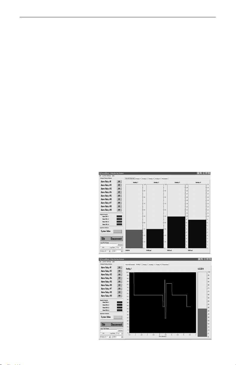
ConsoliDator Multi-Channel Controlle
r
Instruction Manual
CONSOLIDATOR MONITOR SOFTWARE
Each ConsoliDator is shipped with PC software on CD-ROM, which supports monitoring,
data logging and controller setup/programming. You may also download this software from
the web at www.predig.com. There are separate versions of the software for 4-channel and
8-channel models.
Connecting to PC
Many computers are equipped with at least one 9-pin serial port compatible with RS-232.
For distances up to approximately 50 ft, a null-modem cable is adequate. The null modem
cable looks similar to a standard serial cable, except both ends are female, and the
transmit and receive lines in the cable cross-over unlike a standard serial cable. Reference
Serial Communication Connections (page 19) for more information.
Installing Software
Load the ConsoliDator Software CD-ROM into your CD-ROM drive. If the installation does
not load automatically within a few moments, click on the Start button on the Windows®
taskbar, then click RUN. Type x:\ ConsoliDator_ Monitoring_System.exe (where x is your
actual CD-ROM drive letter) and press enter. Follow on-screen instructions.
Using ConsoliDator Monitor Software
Launch the program from the Start menu or desktop shortcut. Make sure you are using the
correct version of the software for the number of channels your model has – 4 or 8. Verify
the controller is powered up and properly connected before proceeding.
From the drop-down menu in the
bottom left of the screen, select
the Modbus ID that matches the
same setting in the controller.
Default is Modbus ID: 1. Click the
Connect button in the lower left
of the screen and allow a moment
for the software to read data in.
Window tabs above the
bargraphs navigate the various
channel displays available. The
screen in the top right is active
when the View All Channels tab
is selected. It shows all Analog
Input bargraphs and numeric
values along with Relay and
Digital Input status. This
information represents real time
data sent from the controller.
Selecting a tab for a specific
channel brings a chart of the style
shown in the bottom right. The
charts show a graphical history
for each Analog Input channel
along with its real time bargraph
and numeric value. There is also
a tab for the flow meter pulse
input channels, which shows
numeric total and numeric and
bargraph rate for all flow
channels.
52
Page 53
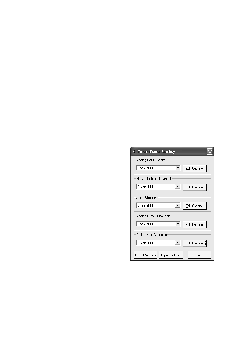
ConsoliDator Multi-Channel Controlle
r
Instruction Manual
Data Logging
The software supports logging input readings to a comma separated value file (*.csv)
compatible with spreadsheet applications. Log settings appear in the lower left of the
screen. First, specify a time interval from the Log Rate options. Note that small intervals will
result in a large file size. If logging for long periods such as days or weeks at a time, it is
suggested that intervals be in the minute or greater range. Next, supply a name in Log File
Name box and click Browse to specify a location to save the file. Lastly, select the Log
checkbox. To view the data, launch your spreadsheet application and open or import the
file. Some spreadsheet applications such as Microsoft
tool that will create presentable graphs and trend lines of your data.
Programming Through Software
The software supports programming of most functions available to the controller. Not
included are some of the General Functions which must be setup on the device itself
through the front buttons. This section is limited to serving as an overview of programming
through software, because the parameters in the software menus correspond to the
parameters on the controller’s setup screens. You will need to follow the Setup and
Programming section (page 21) to understand these parameters. Settings programmed
through software will automatically be updated to the controller and be visible and
accessible in the setup menus of the device.
To begin setup, select System Settings from
the menu bar at the top of the screen. You will
see the window shown to the right. From the
drop-down menus in this window you can access
settings for all inputs, alarms, and outputs.
When functions have been configured and
loaded to the controller, you can choose to store
the settings (configuration) file to your computer
using the Export Settings button. The file may
be used later to restore the configuration or to
create a cloned copy ConsoliDator of the same
model type. You may even take advantage of
this to create multiple configurations modes and
load them as necessary. To write the settings file
to a ConsoliDator, simply click Import Settings
and select the (*.set) file you would like to import
to the controller’s non-volatile system memory.
®
Excel have a chart wizard or other
53
Page 54
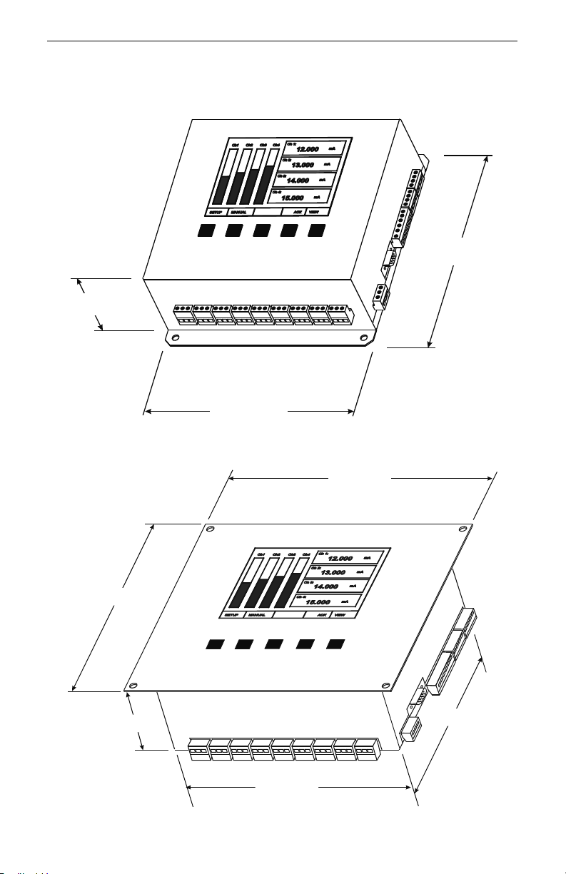
ConsoliDator Multi-Channel Controlle
r
OVERALL DIMENSIONS
3.0" (76mm)
Instruction Manual
8.75" (222mm)
8.66" (220mm)
3.10" (79mm)
8.0" (203mm)
Figure 22. PD980 & PD940 Overall Dimensions
9.36" (238mm)
7.86" (200mm)
Figure 23. PD981 & PD941 Overall Dimensions
54
7.16" (182mm)
Page 55
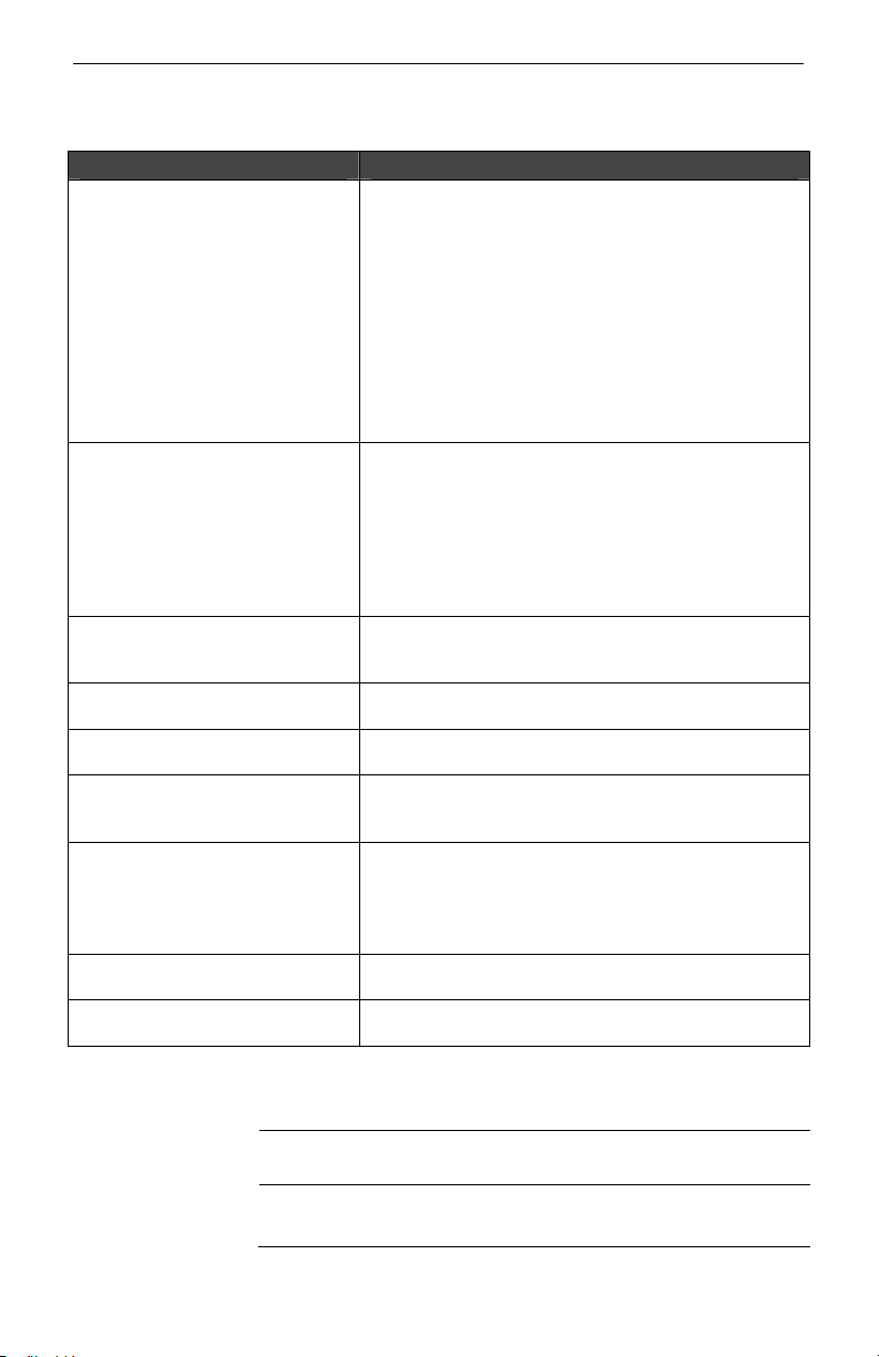
ConsoliDator Multi-Channel Controlle
r
TROUBLESHOOTING TIPS
Symptom Check/Action
1. Contrast is too light: Adjust contrast in main
setup menu.
2. Ambient temperature is below 0°C and affects
No display, or only backlight is
visible, but outputs still function
normally.
Periodic hard resets (power
cycling) or Supervisory alarms.
“NO SENSORS FOUND” is
displayed, but sensors are
connected and transmitting.
Display response seems slower
than normal
Display locks up or the instrument
does not respond at all
Settings reprogrammed, but
instrument behavior remains as
previously programmed
Relay and status do not
respond to signal
Controller will not communicate
serially with other device.
Other symptoms not described
above
LCD visibility: Adjust contrast to compensate.
3. High levels of radiated interference are present.
Steps must be taken to shield controller from
interference or to reduce interference present.
Inductive loads are a possible source of
interference. Reference Switching Inductive
Loads (page 18.)
4. Grounding is inadequate or not connected.
Check earth ground continuity.
1. High levels of radiated interference are present.
Steps must be taken to shield controller from
interference or to reduce interference present.
Inductive loads are a possible source of
interference. Reference Switching Inductive
Loads (page 18.)
2. Grounding is inadequate or not connected.
Check earth ground continuity.
Allow controller to warm-up for 10 or more minutes. If
sensors still not detected, cycle the power to reboot.
Ambient temperature is too cold: Consider installing a
heater with the instrument.
Cycle the power to reboot the microprocessor.
Cycle the power to reboot the microprocessor.
1. Meter must be in Automatic mode in order for
relays to respond to signal. To enter this mode
press the Manual key and follow the on-screen
prompt.
2. Check Setup menu relay set and reset points.
Check baud rates and parity settings. Make sure all
serial devices have agreeing parameters.
Call Technical Support for assistance.
Instruction Manual
Model:
Serial Number:
Password:
55
Page 56

ConsoliDator Multi-Channel Controlle
r
Instruction Manual
How to Contact Precision Digital
For Technical Support please
Call: (800) 610-5239 or (508) 655-7300
Fax: (508) 655-8990
E-mail: [email protected]
For Sales Support
Call: (800) 343-1001 or (508) 655-7300
Fax: (508) 655-8990
E-mail: [email protected]
For the latest version of this Manual please visit:
www.predig.com
LIM980_F
v3.1.1 & Up
05/12
 Loading...