

Page 1
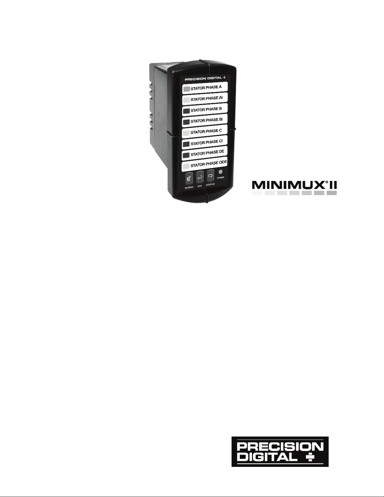
PD138 Minimux® II
Temperature & Process Scanner
• 8 Inputs Per Unit, Eliminates Need for 7 Displays
• Unlimited Number of Units Per System
• Free Custom Message Labels
• Thermocouples, RTDs, Process, AC & DC Inputs
• Internally or Manually Controlled Scanning
• Adjustable Dwell Time for Each Channel
• Independent Alarm Input for Each Channel
• First-Out Alarm Indication
• Alarms Indicated by LEDs, Built-in Horn, and Relay
• Built-In 85 dB Horn with Silence Pushbutton
• Stop-On-Alarmed Channel (field select)
• Non-Interruptible 4-20 mA Inputs
• Sunlight Readable Indication
• NEMA 4X / IP65 Front
• Shallow Depth 1/8 DIN Enclosure
• -40 to 65°C Operating Temperature Range
PRECISION DIGITAL CORPORATION
Find Quality Products Online at: [email protected]
www.GlobalTestSupply.com
Page 2
PD138 Minimux® II Temp & Process Scanner Instruction Manual
Disclaimer
The information contained in this document is subject to change
without notice. Precision Digital makes no representations or
warranties with respect to the contents hereof and specifically
disclaims any implied warranties of merchantability or fitness for a
particular purpose.
!
CAUTION: Read complete
instructions prior to
installation and operation
of the meter.
WARNING: Risk of
electric shock or
personal injury.
Warning
This product is not recommended for life support applications or
applications where malfunctioning could result in personal injury or
property loss. Anyone using this product for such applications does
so at his/her own risk. Precision Digital Corporation shall not be held
liable for damages resulting from such improper use.
Limited Warranty
Precision Digital Corporation warrants this product against defects in
material or workmanship for the specified period under
“Specifications” from the date of shipment from the factory. Precision
Digital’s liability under this limited warranty shall not exceed the
purchase value, repair, or replacement of the defective unit.
Registered Trademarks
All trademarks mentioned in this document are the property of their
respective owners.
© 2009-2015 Precision Digital Corporation. All rights reserved.
2
Find Quality Products Online at: [email protected]
www.GlobalTestSupply.com
Page 3

PD138 Minimux® II Temp & Process Scanner Instruction Manual
Table of Contents
INTRODUCTION ........................................................................... 5
ORDERING INFORMATION ........................................................ 6
SPECIFICATIONS ........................................................................ 7
SETUP AND PROGRAMMING OVERVIEW ................................ 8
SAFETY INFORMATION .............................................................. 9
INSTALLATION ............................................................................ 9
Unpacking ........................................................................................... 9
Panel Mounting ................................................................................. 10
CONNECTIONS OVERVIEW ..................................................... 11
SIGNAL CONNECTIONS ........................................................... 11
Three-Wire RTD Inputs ..................................................................... 12
Thermocouple Inputs ........................................................................ 12
4-20 mA Inputs ................................................................................. 13
Voltage Inputs ................................................................................... 14
MULTIPLE PD138 CONNECTIONS .......................................... 15
ALARM-IN CONNECTIONS ....................................................... 17
ALARM RELAY CONNECTIONS .............................................. 18
Connections ...................................................................................... 18
EXTERNAL SIL, ACK, & STOP/GO CONNECTIONS ............... 19
PROGRAMMING OVERVIEW .................................................... 19
Front Panel Pushbuttons and Status LED Indicators ........................ 19
Programming Dwell Time ................................................................. 21
Programming Dwell Time for Multiple PD138 System ...................... 22
Returning to Four-Second Default Dwell Time ................................. 22
PROGRAMMING ALARM SEQUENCES .................................. 22
Stop or Continuous Scanning On Alarm ........................................... 23
Selecting Alarm Sequence ............................................................... 23
Relay Fail-Safe ................................................................................. 23
OPERATION ............................................................................... 24
Scan, Stop Scan & Quick-Scroll ....................................................... 24
Stop Scan ......................................................................................... 24
Quick-Scroll ...................................................................................... 24
Multiple Units .................................................................................... 25
Built-In Horn ................................................................................. 25
Alarm Relay ................................................................................. 25
SILENCE, STOP/GO & ACK Buttons .......................................... 25
External SILENCE, STOP/GO & ACK Terminals ......................... 25
Alarms .............................................................................................. 26
First-Out Alarms (F2A) ...................................................................... 26
Alarm Indication ................................................................................ 27
3
Find Quality Products Online at: [email protected]
www.GlobalTestSupply.com
Page 4

PD138 Minimux® II Temp & Process Scanner Instruction Manual
ALARM SEQUENCE EXAMPLES ............................................. 28
Sequence A ...................................................................................... 28
If Momentary Alarm ...................................................................... 29
If Maintained Alarm ...................................................................... 29
Sequence F2A .................................................................................. 30
Acknowledge ............................................................................... 31
Stop-On-Alarm .................................................................................. 32
MESSAGE LABELS ................................................................... 33
MOUNTING DIMENSIONS ......................................................... 34
Table of Contents
Figure 1. Panel Cutout and Mounting ................................................ 10
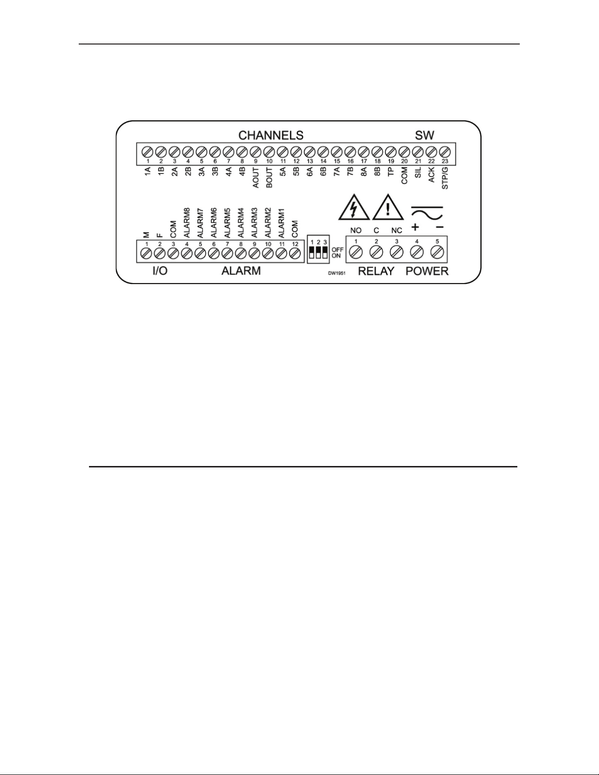
Figure 2. Connector Labeling for PD138 ........................................... 11
Figure 3. Case Dimensions – Side View ............................................ 34
Figure 4. Case Dimensions – Top View ............................................. 34
4
Find Quality Products Online at: [email protected]
www.GlobalTestSupply.com
Page 5

PD138 Minimux® II Temp & Process Scanner Instruction Manual
INTRODUCTION
The Minimux® II is a microprocessor-based eight channel analog input
scanner/multiplexer and annunciator that provides low-cost automatic
switching for multi-point display and alarm systems. Each Minimux
automatically switch up to eight inputs to another device such as a digital
panel meter, controller, or PLC. Multiple units can be connected together
to scan an unlimited number of points. Front panel push-buttons allow for
easy programming of independent adjustable dwell times as well as rapid
channel skipping. The built-in annunciator logic can detect and indicate
which input signals are in alarm condition. The built-i n horn, alarm relay,
and front panel LEDs are sure to catch the operator’s attention. Signal
®
switching is done with reed relays making the Minimux
II ideal for
switching thermocouples, RTDs, control loops, and AC & DC signals.
®
II can
5
Find Quality Products Online at: [email protected]
www.GlobalTestSupply.com
Page 6

PD138 Minimux® II Temp & Process Scanner Instruction Manual
ORDERING INFORMATION
24 VDC
Model
PD138-2 PD138-3 PD138-4 8 Channel Temp & Process Scanner
PD138-2-CL PD138-3-CL PD138-4-CL
Notes:
1. Message la bels for the PD138 may be specified a t time of ord er or later. See pag e 33 for detai ls.
2. There is no special cable required to connect multiple PD138s together.
115 VAC
Model
230 VAC
Model
Description
8 Channel Temp & Process Scanner
with current loop resistor
Enclosures
Model # of Units Description Mounting
PDA2501-V 1 Plastic NEMA 4X Enclosure Through Door
PDA2502-V 2 Plastic NEMA 4X Enclosure Through Door
PDA2503-V 3 Plastic NEMA 4X Enclosure Through Door
PDA2504-V 4 Plastic NEMA 4X Enclosure Through Door
PDA2505-V 5 Plastic NEMA 4X Enclosure Through Door
PDA2506-V 6 Plastic NEMA 4X Enclosure Through Door
PDA2522 2 Plastic NEMA 4X Enclosure; 1(V) 1(H) Through Door
PDA2601-V 1 Stainless Steel NEMA 4X Enclosure Through Door
PDA2602-V 2 Stainless Steel NEMA 4X Enclosure
PDA2603-V 3 Stainless Steel NEMA 4X Enclosure
PDA2604-V 4 Stainless Steel NEMA 4X Enclosure
PDA2605-V 5 Stainless Steel NEMA 4X Enclosure
PDA2606-V 6 Stainless Steel NEMA 4X Enclosure
PDA2622 2 SS NEMA 4X Enclosure; 1(V) 1(H)
PDA2701-V 1 Steel NEMA 4 Enclosure
PDA2702-V 2 Steel NEMA 4 Enclosure
PDA2703-V 3 Steel NEMA 4 Enclosure
PDA2704-V 4 Steel NEMA 4 Enclosure
PDA2705-V 5 Steel NEMA 4 Enclosure
PDA2706-V 6 Steel NEMA 4 Enclosure
PDA2722 2 Steel NEMA 4 Enclosure; 1(V) 1(H)
PDA2801 1 Plastic NEMA 4X Enclosure
Through Door
Through Door
Through Door
Through Door
Through Door
Through Door
Through Door
Through Door
Through Door
Through Door
Through Door
Through Door
Through Door
Through Cover
Systems
Model Description Kit Components
PD765-6R2-00
PD138-3
PDA2821
PD765-6X2-00
PD138-3
PDA2821
PDS178
PDS178X2
Temperature
Scanning & Alarming
System
Large Display
Temperature
Scanning & Alarming
System
6
Find Quality Products Online at: [email protected]
www.GlobalTestSupply.com
Process & Temperature
Meter
Minimux II
Plastic NEMA 4X Enclosure
Trident X2 Meter
MINIMUX II Scanner
Plastic NEMA 4X Enclosure
Page 7

PD138 Minimux® II Temp & Process Scanner Instruction Manual
SPECIFICATIONS
Number of Channels per
Minimux
Number of Channels per
System
Signals Switching DPST reed relays
Contact Resistance 0.2 maximum
Maximum Input Voltage 200 V (switched or common mode)
Maximum Current
Switched
Maximum Power Switched 10 W
Dwell Time Each channel adjustable from 0.6 to 30
Non-Volatile Memory All programming values are stored in non-
Scan Method Internal or manually controlled
Channel Indication Green LED on front panel
Disabling Channels Any channel may be disabled
8 double-pole channels per unit
Unlimited
0.5 A
seconds
volatile
memory for ten years if power is lost
Scan Stop The scan may be stopped by pressing and
holding the STOP/GO button for more than 0.5
seconds. The scan may be resumed by
pressing and releasing the STOP/GO button
quickly (less than 0.5 seconds)
Alarm Input Independent alarm input for each channel.
Input Impedance; 25 Kohm, typical pull-up to 5
V
Alarm Sequence Sequence A or Sequence F2A (First-Out)
Alarm Out p uts Alarm condition indicated by:
1. Front panel red LED for each channel.
2. Relay, 1 SPDT (form C); rated 2 A @ 30
VDC or 2 A @ 250 VAC resistive load;
1/14 HP @ 125 / 250 VAC for inductive
loads. For fail-safe operation, the relay is
energized in the non-alarm state. In the
case of a power failure, the relay will go to
the alarm state, (NC contact is connected
to common).
3. Built-in horn, 85 dB.
4. Stop-on-alarmed-channel (user select)
Alarm Acknowledge Front panel ACK and rear connector terminals
External Switch Functions The functions of the front panel buttons are
available at screw terminals at the rear of the
instrument
7
Find Quality Products Online at: [email protected]
www.GlobalTestSupply.com
Page 8

PD138 Minimux® II Temp & Process Scanner Instruction Manual
Message Labels Free, custom printed, 2 lines per message at
14 characters per line. Factory or field
printable. See page 33 or www.predig.com
for details.
Connections Removable screw terminal connectors
provided:
Power + Relay 22 to 12 AWG
Alarm Input, Analog
Signal, External
Switches, I/O
Environmental Operating temperature -40°C to 65°C
Storage temperature -40°C to 85°C
Relative humidity 0 to 95% non-
Power Options
Based On Model Number
LED Test All LEDs are tested on power-up
Enclosure 1/8 DIN, high impact plastic, UL94V-0
Front Panel NEMA 4X, panel gasket provided
Warranty 3 years parts and labor
115 VAC, ± 10%, 50/60 Hz, 4 VA
230 VAC, ± 10%, 50/60 Hz, 4 VA
12-24 VDC (9-18 VAC, 50/60 Hz) 2 W
30 to 16 AWG
condensing
SETUP AND PROGRAMMING OVERVIEW
Programming and installing the PD138 involves three basic steps:
1) Connections
a) AC power
b) Signal inputs and output
c) Multiple PD138s (if needed)
d) Alarm-Inputs (if needed)
e) Alarm relay (if needed)
f) External switch inputs (if needed)
2) DIP Switch Setup
a) Sequence A or Sequence F2A alarm operation
b) Stopping-on-alarm or to continue scanning on alarm
c) Relay fail-safe
3) Programming the PD138 for various functions:
a) Channels to scan
b) Dwell times of scanned channels
8
Find Quality Products Online at: [email protected]
www.GlobalTestSupply.com
Page 9
PD138 Minimux® II Temp & Process Scanner Instruction Manual
SAFETY INFORMATION
!
CAUTION: Read complete
instructions prior to
installation and operation
of the instrument.
WARNING
Hazardous voltages exist within enclosure. Installation and service should
be performed only by trained service personnel.
WARNING: Risk of
electric shock.
INSTALLATION
There is no need to remove the instrument from its case to
complete the installation, wiring, and setup.
Unpacking
Remove the instrument from box. Inspect the packaging and
contents for damage. Report damages, if any, to the carrier.
If any part is missing or the unit malfunctions, please contact your
supplier or the factory for assistance.
9
Find Quality Products Online at: [email protected]
www.GlobalTestSupply.com
Page 10
PD138 Minimux® II Temp & Process Scanner Instruction Manual
Panel Mounting
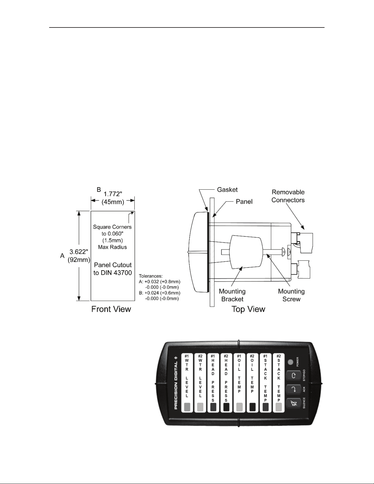
• Prepare a standard 1/8 DIN vertical panel cutout – 1.772 " x 3.622"
(45 mm x 92 mm). Refer to Figure 1 for more details.
• Clearance: allow at least 4" (102 mm) behind the panel for wiring.
• Panel thickness: 0.04" - 0.25" (1.0 mm - 6.4 mm).
Recommended minimum panel thickness to maintain Type 4X
rating: 0.06" (1.5 mm) steel panel, 0.16" (4.1 mm) plastic panel.
• Remove the two mounting brackets provided with the meter (back-off
the two screws so that there is ¼" (6.4 mm) or less through the
bracket. Slide the bracket toward the front of the case and remove).
• Insert the unit into the panel cutout.
• Install mounting brackets and tighten the screws against the panel.
To achieve a proper seal, tighten the mounting bracket screws
evenly until the front is snug to the panel along its short side. DO
NOT OVER TIGHTEN, as the rear of the panel may be damaged.
Figure 1. Panel Cutout and Mounting
Note: The PD138 can
be horizontally mounted .
Free custom message
labels can be ordered to
align with horizontal
mounting, see page 33
or www.predig.com for
details.
Find Quality Products Online at: [email protected]
10
www.GlobalTestSupply.com
Page 11
PD138 Minimux® II Temp & Process Scanner Instruction Manual
CONNECTIONS OVERVIEW
All connections are made to removable screw terminal connections which
are supplied with each PD138.
Figure 2. Connector Labeling for PD138
SIGNAL CONNECTIONS
Signal input and output connections for the Minimux
position removable screw terminal connector supplied with each unit. The
following table gives the input and output terminal assignments:
SCREW TERMINAL
CHANNEL + LINE - LINE RTD
3-wire RTD tie point TP
Input 1 1A 1B
Input 2 2A 2B
Input 3 3A 3B
Input 4 4A 4B
Input 5 5A 5B
Input 6 6A 6B
Input 7 7A 7B
Input 8 8A 8B
Output Output A Output B
®
II are made to a 23
COMMON
11
Find Quality Products Online at: [email protected]
www.GlobalTestSupply.com
Page 12
PD138 Minimux® II Temp & Process Scanner Instruction Manual
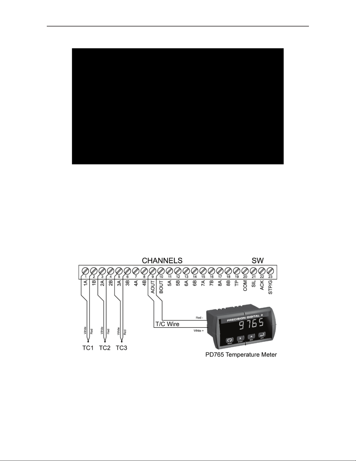
Three-Wire RTD Inputs
Note:
Three-wire inputs such as thermistors and RTDs can be handled by
switching the two common wires and connecting the third wire of each
sensor to the TP terminal and to the temperature meter.
• Connect like color leads to terminals 1A & 1B, 2A & 2B, 3A & 3B, etc.
• Connect odd color leads to terminal TP.
• Connect outputs A, B and TP to the temperature meter.
Thermocouple Inputs
Note:
Thermocouple wire must be used between the Minimux
®
II and the meter.
12
Find Quality Products Online at: [email protected]
www.GlobalTestSupply.com
Page 13
PD138 Minimux® II Temp & Process Scanner Instruction Manual
4-20 mA Inputs
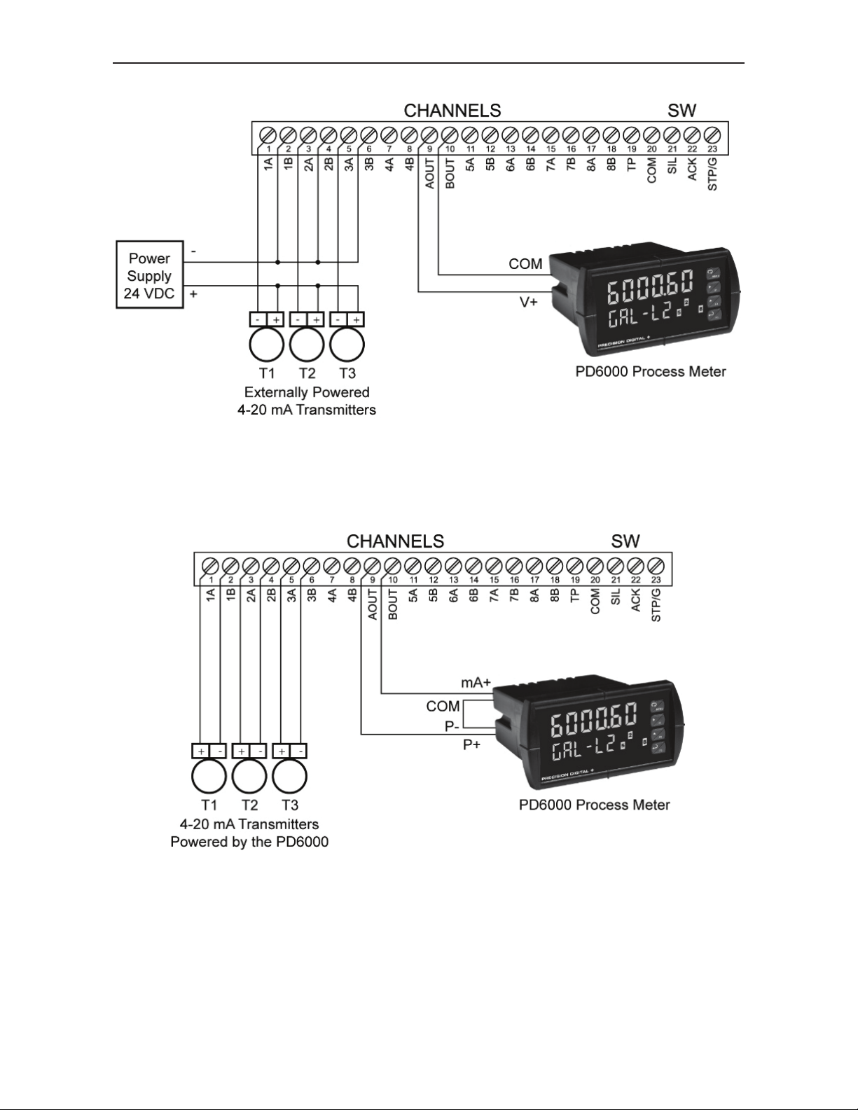
A special version of the Minimux
®
II is used to switch 4-20 mA signals.
PD138-X-CL versions have a built-in resistor network that eliminates loop
interruptions. The process meter must be setup for 1-5 V input and the
complete system should be calibrated together.
The PD6000’s internal transmitter power supply may be used to power the
transmitters. However, only the transmitter that is currently selected will
be powered and all others will not be po wered. Care should be taken to
provide the transmitter with sufficient time to stabilize to provide an
accurate output.
13
Find Quality Products Online at: [email protected]
www.GlobalTestSupply.com
Page 14
PD138 Minimux® II Temp & Process Scanner Instruction Manual
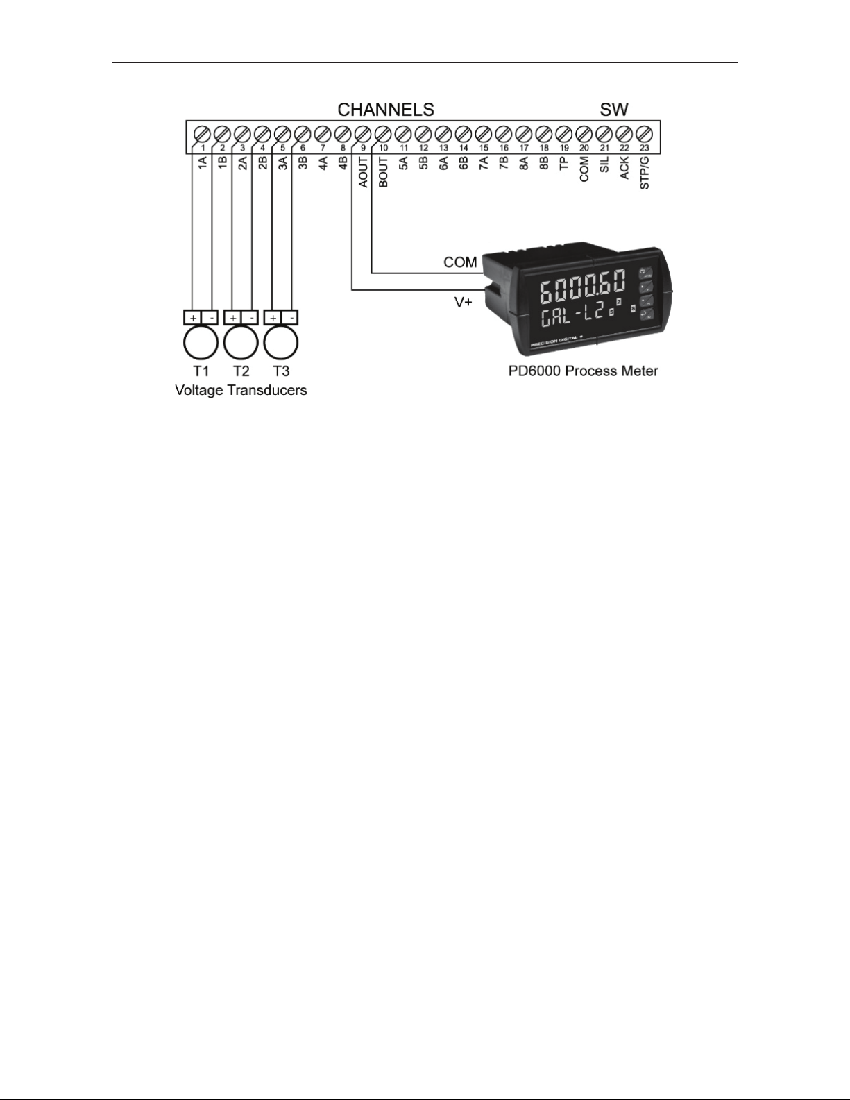
Voltage Inputs
14
Find Quality Products Online at: [email protected]
www.GlobalTestSupply.com
Page 15
PD138 Minimux® II Temp & Process Scanner Instruction Manual
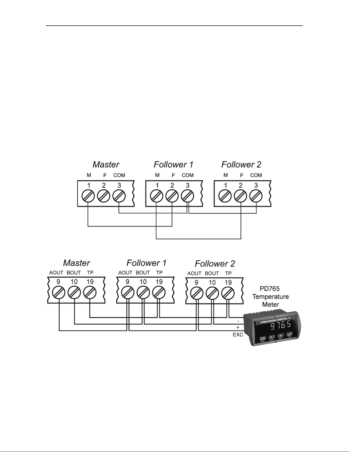
MULTIPLE PD138 CONNECTIONS
Multiple Minimux® II can be connected together to increase multiplexing
capacity for an unlimited number of points. When connecting several units
together, one unit of the group is designated the master unit and all other
units function as follower units. Multiple unit configuration is simply done
by connecting the units together as shown below. The system will selfdetermine if there are two or more Minimux
No special cable is needed to connect multiple PD138s together.
There are three connections that must be made to connect multiple
PD138s into a system:
1. Master/Follower Connections
®
II connected together.
2. Multiplexer Output Signal Connections
The inputs to each unit are connected as for single units. The outputs of
all Minimux
®
II (terminals output A, output B, and TP) are connected in
parallel and then connected to the display meter.
Notes:
1. Use thermocouple wire when interconnecting a thermocouple system.
2. Terminals TP are only used in a three-wire RTD application.
15
Find Quality Products Online at: [email protected]
www.GlobalTestSupply.com
Page 16
PD138 Minimux® II Temp & Process Scanner Instruction Manual
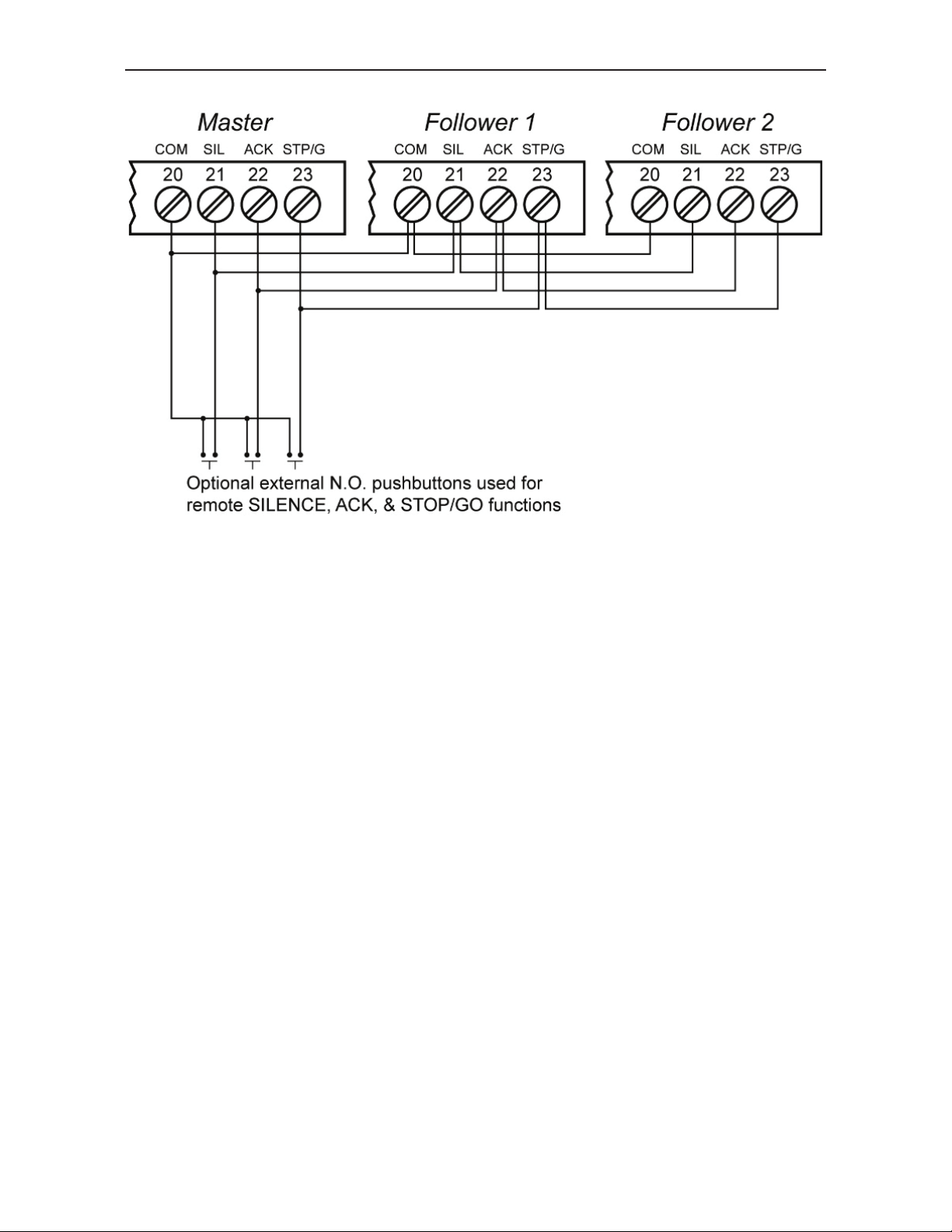
3. Silence, Acknowledge, & Stop/Go Connections
Connecting the ACK & STOP/GO terminals of all units in a multiple-unit
system allows the operator to control and acknowledge alarms from any
unit in the system or via external switches. However, each Minimux
®
II’s
relay will operate independently, so it may be necessary to wire them in
®
parallel to drive a single alarm device. Also, each Minimux
II’s internal
horn operates independently.
Other Connections
Connections for Power, Signal Inputs, Alarm-In, and Alarm Relay are all
made the same way as for single units.
16
Find Quality Products Online at: [email protected]
www.GlobalTestSupply.com
Page 17

PD138 Minimux® II Temp & Process Scanner Instruction Manual
ALARM-IN CONNECTIONS
Each channel on the PD138 has its own Alarm-In line that provides
independent alarm indication capability for each channel. The alarm
input lines of the PD138 are normally high (pull-up to 5V). Relay contacts
from a Precision Digital meter or a low level logic output from a PLC can
be used to drive the PD138 alarm input lines.
Note:
Under normal condition the NC contact of the PD6000 is opened
(failsafe). When the PD6000 goes to alarm the corresponding relay
transfers connecting the NC and C contacts together causing an alarm
condition to be detected on the PD138.
17
Find Quality Products Online at: [email protected]
www.GlobalTestSupply.com
Page 18

PD138 Minimux® II Temp & Process Scanner Instruction Manual
ALARM RELAY CONNECTIONS
One SPDT relay is provided with each unit. This alarm relay is common
to all channels and is activated when the PD138 detects an alarm. The
relay resets when the alarm is acknowledged .
Connections
Refer to the diagram below to wire up the alarm relay.
®
When connecting two or more Minimux
to wire the relays in parallel to drive a single alarm device.
II together it may be necessary
For fail-safe operation, the relay is energized in the non-alarm state. In
the case of a power failure, the relay will go to the alarm state, (NC
contact is connected to C). See page 23 for details
18
Find Quality Products Online at: [email protected]
www.GlobalTestSupply.com
Page 19
PD138 Minimux® II Temp & Process Scanner Instruction Manual
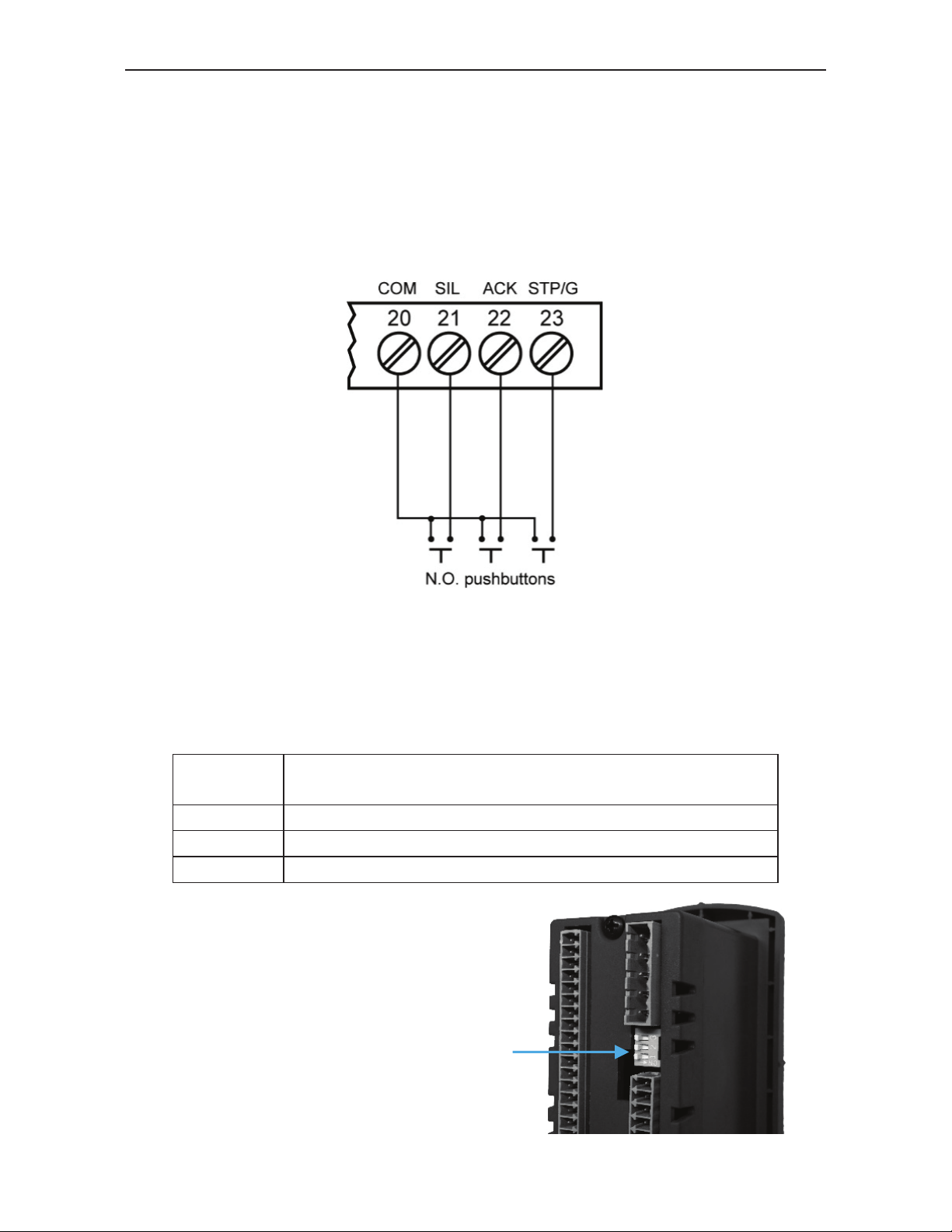
EXTERNAL SIL, ACK, & STOP/GO CONNECTIONS
Terminals at the rear of the instrument allow the functions of the
SILENCE, ACK, and STOP/GO buttons to be performed externally. For
instance, if the PD138 is mounted inside a NEMA 4X enclosure,
switches mounted outside the enclosure could be wired to these
terminals to provide the user with access to the SILENCE, ACK, and
STOP/GO functions.
PROGRAMMING OVERVIEW
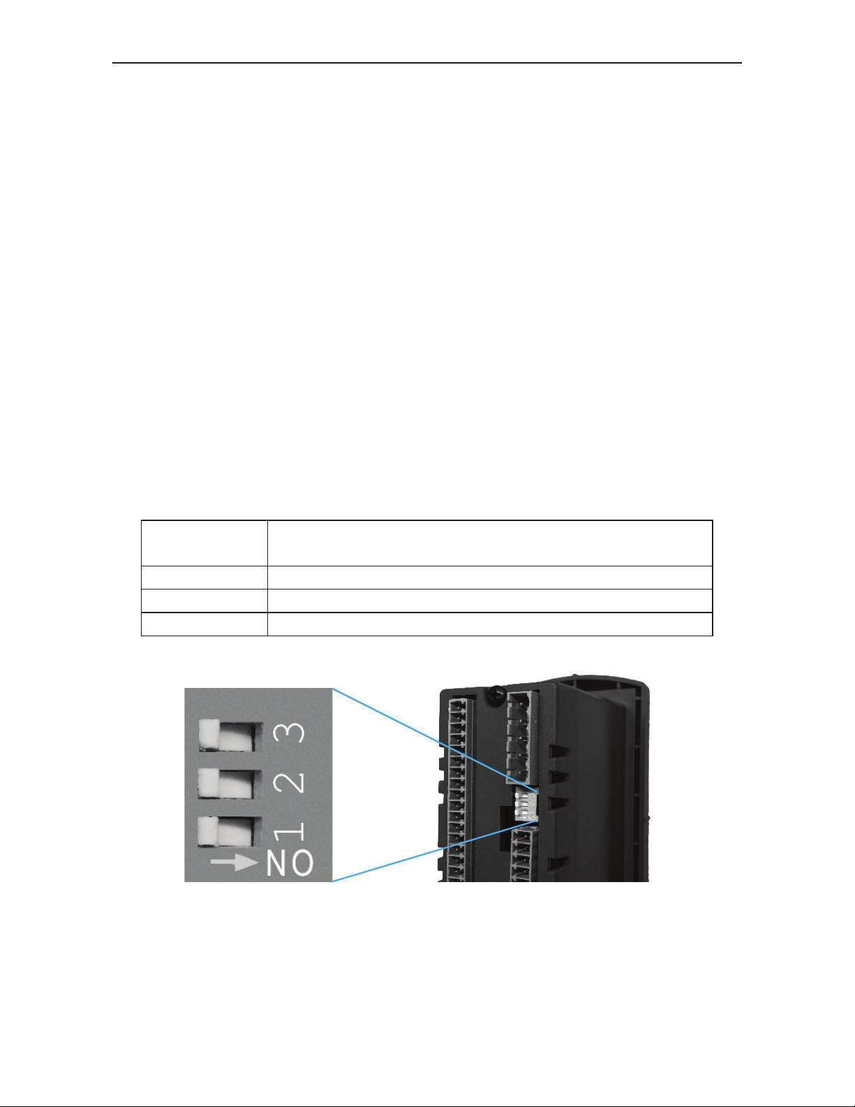
The PD138 is programmed for scanning and alarm function s using the
front panel buttons and a three-position DIP switch. The DIP switch is
used to program the following:
DIP
Position
1 Stopping-on-alarm or continuous scan-on-alarm
2 Sequence A or F2A alarm operation
3 Relay fail-safe or normal operation
The DIP switch is located on the back of
the unit. These switches program the unit
for alarm Sequence A or F2A, stop-onalarm, and for fail-safe operation.
Function
DIP Switch
19
Find Quality Products Online at: [email protected]
www.GlobalTestSupply.com
Page 20
PD138 Minimux® II Temp & Process Scanner Instruction Manual
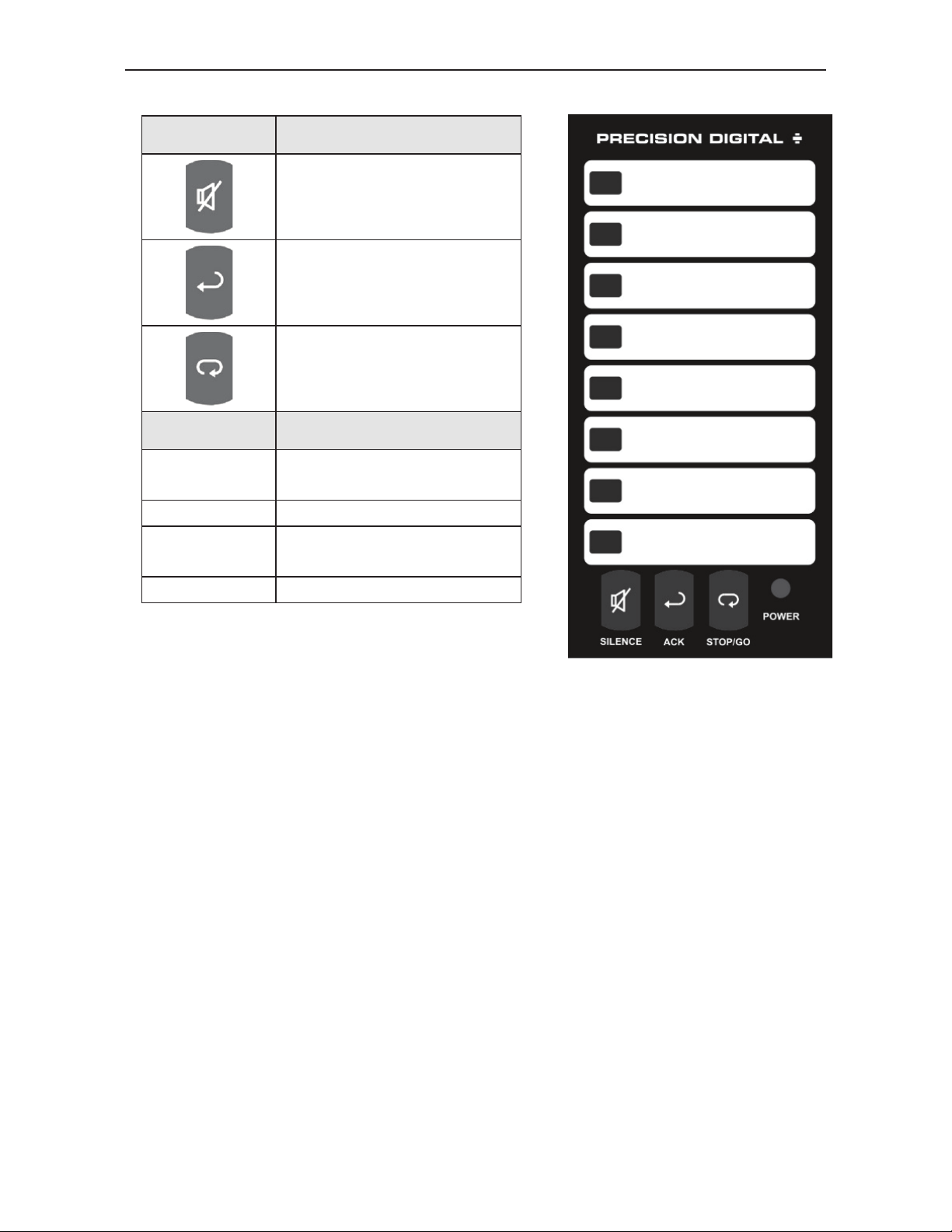
Front Panel Pushbuttons and Status LED Indicators
Button Description
Silence Horn
Acknowledge
Alarm
Stop/Go
LED Description
Red
Green Current Channel
Yellow
Power Indicates power is on.
Channel Alarm
Status Indicators
Current Channel in
Alarm Condition
20
Find Quality Products Online at: [email protected]
www.GlobalTestSupply.com
Page 21

PD138 Minimux® II Temp & Process Scanner Instruction Manual
Programming Dwell Time
The default dwell time for the PD138 is four seconds per channel and it
can be adjusted for any time between 0.6 and 30 seconds per channel.
A channel can be disabled from the scan sequence by programming that
channel’s dwell time for less than 0.5 seconds during setup.
To program a dwell time for other than the four second default or to
disable a channel altogether:
1. Press and hold SILENCE and STOP/GO for 3 seconds until all
LEDs cycle, then release
2. Press and release SILENCE while the LEDs cycle (they will cycle 3
times)
3. Press and release STOP/GO while the LEDs blink as a group (they
will blink 3 times)
Note: While entering the programming mode the POWER LED will
blink green but will turn red during the actual programming mode.
4. Unit will beep and channel 1 will illuminate, indicating PD138 is
ready to be programmed.
5. Dwell times are programmed with the STOP/GO button;
• Press and release STOP/GO button within 0.5 seconds to
disable a selected channel.
• Press and release STOP/GO button after the 0.5 seconds
beep to program channel for minimum dwell time.
• Press and hold STOP/GO button for desired length of d well
time up to 30 seconds maximum.
6. After the STOP/GO button is released the unit will beep and go to
the next channel.
7. Program the remaining channels in a similar fashion.
8. When the dwell times for all eight channels have been programmed,
a red LED will light up next to channels that have been disabled.
9. The ACK button is used to advance to the desired channel.
10. When the dwell times have been programmed as desired press the
silence button.
21
Find Quality Products Online at: [email protected]
www.GlobalTestSupply.com
Page 22
PD138 Minimux® II Temp & Process Scanner Instruction Manual
Programming Dwell Time for Multiple PD138 System
The dwell times for each PD138 in a multiple PD138 system need to be
programmed individually.
Returning to Four-Second Default Dwell Time
To return to the default dwell time of four seconds per channel:
1. Turn the power off
2. Apply power while holding the STOP/GO button.
3. Release the STOP/GO button two seconds after power has been
applied.
All dwell time programming is stored in non-volatile memory for 10 years
if power is lost.
PROGRAMMING ALARM SEQUENCES
The DIP switch described on page 19 is used to program the following
alarm functions:
DIP
Switch
Position 1 Stop-on-alarm or continuous scan-on-alarm
Position 2 Sequence A or F2A alarm operation
Position 3 Relay Failsafe
Function
22
Find Quality Products Online at: [email protected]
www.GlobalTestSupply.com
Page 23

PD138 Minimux® II Temp & Process Scanner Instruction Manual
Stop or Continuous Scanning On Alarm
The PD138 can be programmed to either stop or continue scanning
when it encounters a channel in alarm. See page 22 for further details on
this function
DIP
Switch 1
Position
OFF Continuous scan (Factory Default Setting)
ON Stop-on-alarm
Function
Selecting Alarm Sequence
The PD138 can be programmed to respond to alarm conditions either via
Sequence A or Sequence F2A. Refer to page 26 for a description of
these sequences.
DIP
Switch 2
Position
OFF A (Factory Default Setting)
ON F2A
Alarm Sequence
Relay Fail-Safe
In fail-safe operation, a relay coil is energized in non-alarm condition. In
case of power failure, relays will go to alarm state.
DIP
Switch 3
Position
OFF Non-Fail-Safe (Factory Default Setting)
ON Fail-Safe
Note: The power must be cycled after making changes to the fail-safe
operation.
Relay Action
23
Find Quality Products Online at: [email protected]
www.GlobalTestSupply.com
Page 24

PD138 Minimux® II Temp & Process Scanner Instruction Manual
OPERATION
In its most basic form, the PD138 is the electrical equivalent to a doublepole, eight position automatic switch. That is, whatever input is brought
into the PD138 is dwelled on for a certain amount of time while being
switched back out to another device. For example, a typical application
may involve switching eight type J thermocouples into a single digital
panel meter.
The PD138 is made more useful by adding the ability to indicate alarm
conditions. The PD138 can be programmed for either of t wo alarm
sequences and it will indicate alarm conditions in three ways:
1. A red LED lights up next to a message label
2. A built-in horn sounds
3. A 2 amp relay transfers.
Once all the connections have been made to the PD138 and it has been
programmed for the particular application, it operates pretty much on its
own.
The only intervention it might receive from an operator would be to stop
the scan on a particular channel or to acknowledge an alarm.
Scan, Stop Scan & Quick-Scroll
The PD138 automatically scans through each active chann el, dwells on
that channel for the programmed dwell time, while at the same time
switching the signal to an external device.
Stop Scan
The PD138 can be stopped on the current channel by pressing and
holding the STOP/GO key for more than 0.5 seconds. The PD138 will
beep once to announce that scanning has stopped. To resume scanning,
press and release the STOP/GO key quickly (less than 0.5 seconds).
Quick-Scroll
To quickly scroll through the channels press the STOP/GO button
quickly (less than 0.5 seconds). Repeat until desired channel is reached.
24
Find Quality Products Online at: [email protected]
www.GlobalTestSupply.com
Page 25

PD138 Minimux® II Temp & Process Scanner Instruction Manual
Multiple Units
A system made up of multiple PD138s does not require any special
setup or programming. In fact, the model number is the same for all units
and they operate in the same manner as single units. There are several
terminals on each PD138 in the system that have to be connected
together, but this does not require a special cable. Instructions for these
connections are described in the Multiple PD138 Connections on page
15.
In a multiple unit system, the scan will progress through each channel on
the first PD138, move on to the first channel on the second PD138, scan
through its active channels and then move on to additional PD13 8s in
the same manner and then finally come back around to the first channel
of the first PD138.
Built-In Horn
Each PD138 has an independent built-in horn. In a multiple unit system
the built-in horn of the unit where the alarm condition occurred will
activate.
Alarm Relay
In a multiple unit system, only the alarm relay of the unit where the alarm
occurred will transfer. The user can wire the alarm relays for all units in
parallel to drive a single alarm device.
SILENCE, STOP/GO & ACK Buttons
Connecting the SILENCE, STOP/GO and ACK terminals at the rear of all
units in a multiple-unit system allows the operator to control and
acknowledge alarms from any unit in the system.
External SILENCE, STOP/GO & ACK Terminals
Connecting a N.O. pushbutton switch across all the STOP/GO & COM
terminals in a multiple-unit system allows the operator to control the
®
Minimux
across all the ACK & COM terminals in a multiple-input system allows
the operator to acknowledge alarms at a remote location. Connecting a
N.O. push-button switch across all the SILENCE & COM terminals in a
multiple-input system allows the operator to silence the PD138 at a
remote location.
II at a remote location. Connecting a N.O. push-button switch
25
Find Quality Products Online at: [email protected]
www.GlobalTestSupply.com
Page 26

PD138 Minimux® II Temp & Process Scanner Instruction Manual
Alarms
Each channel of the Minimux® II has an independent ‘Alarm-In’ terminal
that allows an external device to trigger an alarm on the Min imux
external device may be the relay contacts on a digital panel meter, such
as the PD765-6R2-00, or the digital output from a PLC. When an
external device detects an alarm condition, it drives the appropriate
®
Alarm-In line on the Minimux
II low. When the PD138 reaches this
channel, its LED will turn red and flash, the built-in horn will sound and
the alarm relay will transfer.
Alarms are acknowledged by pressing the ACK button or closing a
pushbutton wired across terminals at the rear of the instrument. When an
alarm is acknowledged, the horn will silence and the relay will change
state. The alarmed LED (red) will not return to norma l until the alarm
condition has been corrected and that channel is scanne d a gain.
The PD138 can be field programmed to react to alarm conditions i n on e
of two ways: Sequence A or Sequence F2A (first-out). Sequence A
detects both momentary and maintained alarms. Sequence F2A also
detects both momentary and maintained alarms as well as which alarms
occurred first on a complete scan cycle.
®
II. The
First-Out Alarms (F2A)
The main feature of Sequence F2A is its ability to indicate which alarms
occurred first. In a system where all inputs are monitored simultaneously,
this is a fairly straightforward concept. However, in a scanned system
such as one using a PD138, where the inputs are monitored one at a
time, it is not really possible to tell which alarm really occurred first. All
that is known is which alarm was detected first. For this reason, the
PD138 recognizes first-out alarms as all alarms that occur during
the first complete scan. This is from the time the unit detects the
first alarm until the scanning goes around and passes through that
first alarmed point once again. First-out alarms are indicated by
flashing red LEDs. Secondary alarms are indicated by steady red
LEDs.
The PD138 detects an alarm only if the alarm is present (alarm-in line is
low) while the channel is being scanned. For dwell times gr eater than 2
seconds, the ‘alarm-in’ line is poled after the PD138 has been on that
channel for 2 seconds. If the dwell time is less than 2 seconds, the
‘alarm-in’ line is poled 0.05 seconds before the PD138 moves on to the
next channel.
26
Find Quality Products Online at: [email protected]
www.GlobalTestSupply.com
Page 27

PD138 Minimux® II Temp & Process Scanner Instruction Manual
Alarm Indication
The PD138 indicates alarms in 3 ways:
1) A normally green LED turns to red and flashes
2) An internal horn sounds
3) An alarm relay transfers.
The way red LEDs behave during an alarm depends on whether the
PD138 was programmed to respond to alarms via Sequen ce A or
Sequence F2A. Both of these sequences handle both momentary and
maintained alarms; Sequence F2A also indicates which group of alarms
occurred first.
27
Find Quality Products Online at: [email protected]
www.GlobalTestSupply.com
Page 28
PD138 Minimux® II Temp & Process Scanner Instruction Manual
ALARM SEQUENCE EXAMPLES
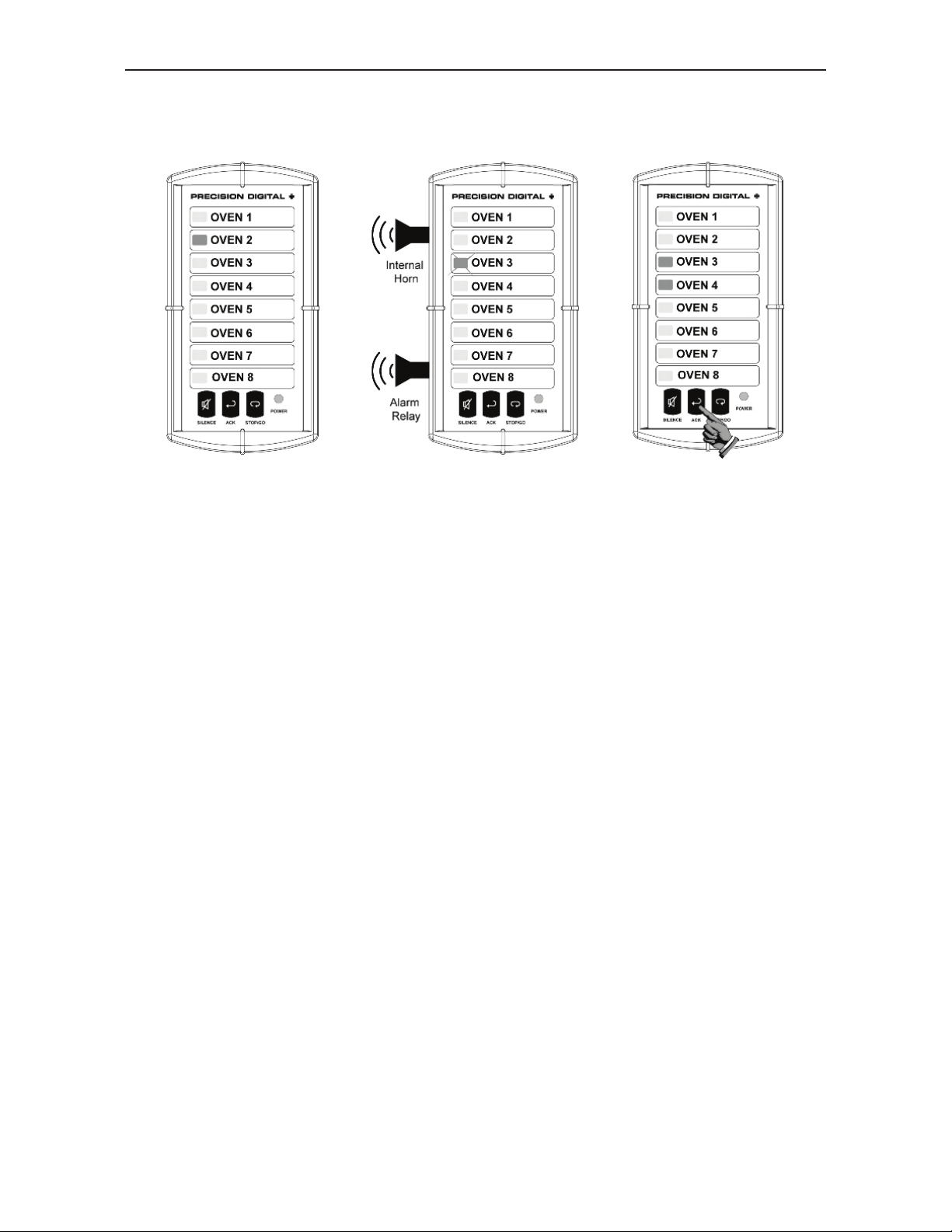
Sequence A
The PD138 is
scann
ing all the
selected inputs and
is currently at
channel 2, as
indicated by a green
LED.
After the Minimux
®
II
has dwelled on
channel 3 for the
appropriate settling
time, it poles channel
3’s alarm-in line and
finds it to be in alarm.
The LED starts
flashing yellow (red
and green), the horn
sounds and the alarm
relay transfers.
The unit continues to
scan other points
and an operator
acknowledges the
alarm. The internal
horn is silenced, the
alarm relay transfers,
and the number 3
LED goes to steady
red.
28
Find Quality Products Online at: [email protected]
www.GlobalTestSupply.com
Page 29
PD138 Minimux® II Temp & Process Scanner Instruction Manual
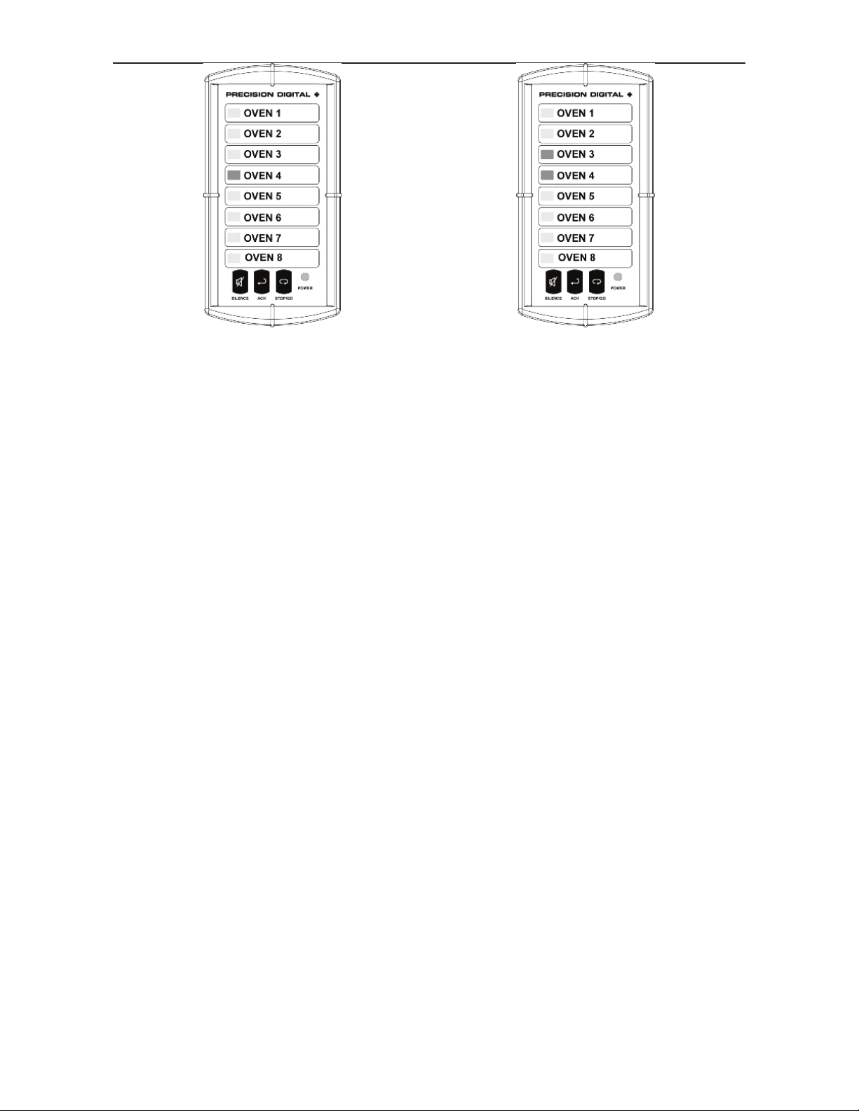
If Momentary Alarm
When the Minimux® II returns to
channel 3, the LED will appear
yellow (a combination of green
and red). Before the Minimux
moves on to the next channel it
will
check the alarm-in line for
channel 3 and find the alarm is
gone (momentary) and turn off
the red
LED. Channel 3’s LED will
appear green before the
®
Minimux
4.
II moves on to channel
®
II
If Maintained Alarm
When the Minimux® II returns to
channel 3, the LED will appear
yellow (a combination of green
and red). Before the Minimux
moves on to the next channel it
will check the alarm-in line for
channel
3 and find the alarm is still there
(maintained) and it will not turn
the red LED off.
®
II
29
Find Quality Products Online at: [email protected]
www.GlobalTestSupply.com
Page 30
PD138 Minimux® II Temp & Process Scanner Instruction Manual
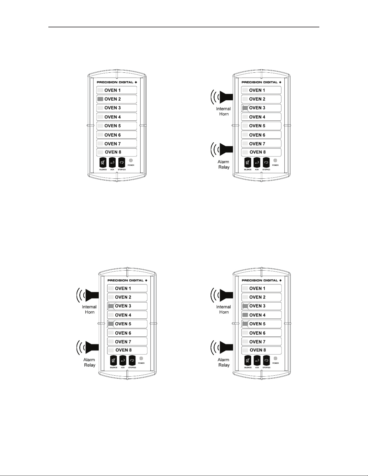
Sequence F2A
The main feature of Sequence F2A is its ability to indicate which alarms
occurred first (on a scan cycle, see page 26).
1
The PD138 is scanning all the
selected inputs and is currently at
channel 2, as indicated by a
green LED.
2
After the Minimux
on channel 3 for the appropriate
settling time, it poles channel 3’s
alarm-in line and finds it to be in
alarm. The LED starts flashing
yellow (red and green), the horn
sounds and the alarm relay
transfers.
®
II has dwelled
3
Channel 5 is also found to be in
alarm and the LED flashes
because it was detected during
the same scan cycle that the first
alarm was detected.
4
Channel 4 is found to be in alarm
and is indicated by a steady LED
because it was found after a
complete scan of all inputs after
the first alarm was detected.
30
Find Quality Products Online at: [email protected]
www.GlobalTestSupply.com
Page 31
PD138 Minimux® II Temp & Process Scanner Instruction Manual
Acknowledge
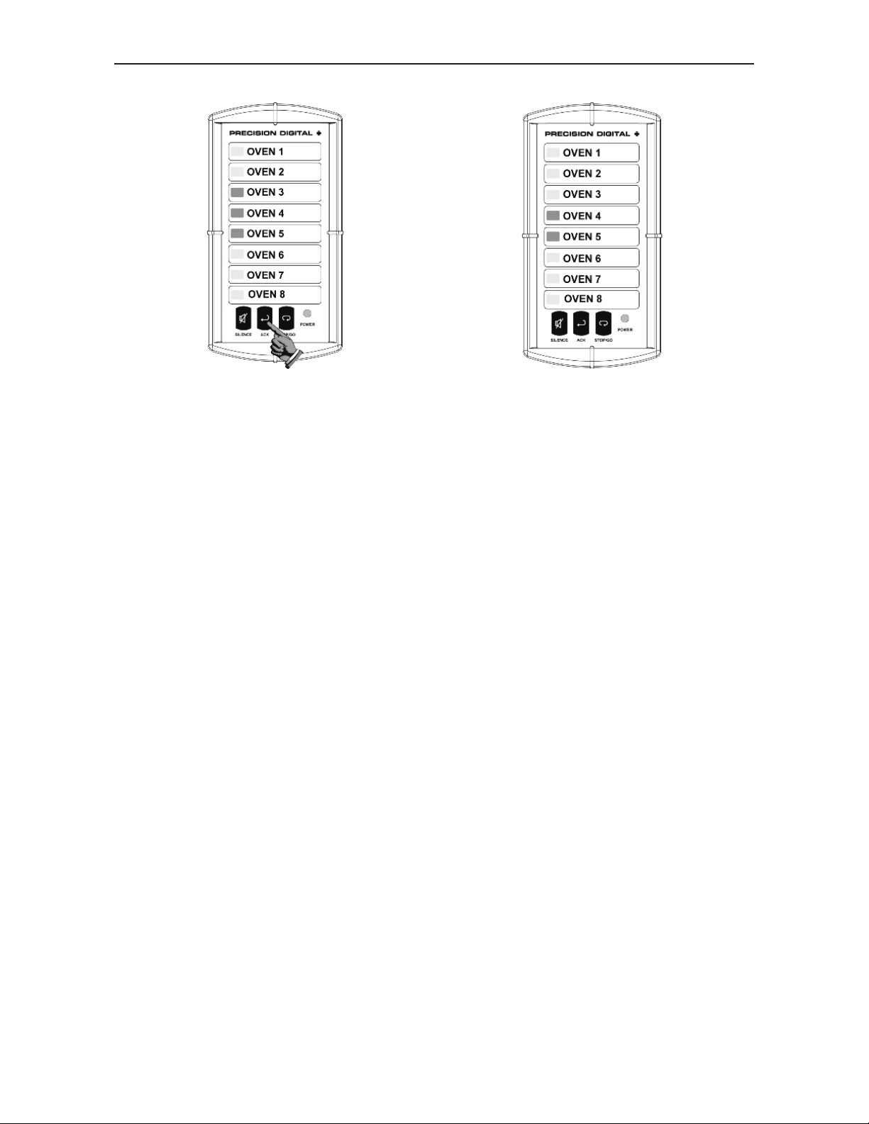
5 6
The unit continues to scan and
an operator acknowledges the
alarm. All LEDs go to steady, the
internal horn is silenced, and the
alarm relay transfers. When the
Minimux
®
II returns to channel 3,
the LED will appear yellow. Just
®
before the Minimux
II moves on
to the next channel it will check
the alarm-in line and find the
alarm is still there and it will not
turn the red LED off.
®
The Minimux
II continues to
scan and again returns to
channel 3, the LED will appear
yellow. Just before the Minimux
®
II moves on to the next channel it
will check the alarm-in line and
find the alarm is gone and turns
off the red LED. Channel 3’s LED
will appear green before the
®
Minimux
II moves on to channel
4, which will appear yellow.
31
Find Quality Products Online at: [email protected]
www.GlobalTestSupply.com
Page 32

PD138 Minimux® II Temp & Process Scanner Instruction Manual
Stop-On-Alarm
The PD138 can be programmed to stop scanning when an alarm
condition is detected by setting DIP switch 1 to the ON position, as
described on page 22.
If the DIP switch is in the ON position, the PD138 will stop when it
encounters an alarm and the LED will begin to flash yellow (combination
of red and green), the horn will sound and the alarm relay will transfer.
There are now two ways to proceed:
1. Acknowledge the alarm and move on to the next channel by
pressing the ACK button. This will cause the horn to silence and the
relay to transfer.
2. Remain on the alarmed channel and acknowledge the alarm by
pressing and holding the STOP/GO button for more than 0.5
seconds to freeze the scan and then pressing the ACK button to
acknowledge the alarm. To resume the scan, press and release the
STOP/GO button quickly (less than 0.5 seconds).
If the original alarm has been acknowledged but has not been corrected
by the time the scan reaches it again, the scan will stop, but the horn and
the relay will not alarm. If the alarm condition has been corrected, the
PD138 will continue scanning as normal and the red LED will turn off. If
the alarm has not been corrected press the ACK button to continue
scanning.
32
Find Quality Products Online at: [email protected]
www.GlobalTestSupply.com
Page 33
PD138 Minimux® II Temp & Process Scanner Instruction Manual
)
(
)
MESSAGE LABELS
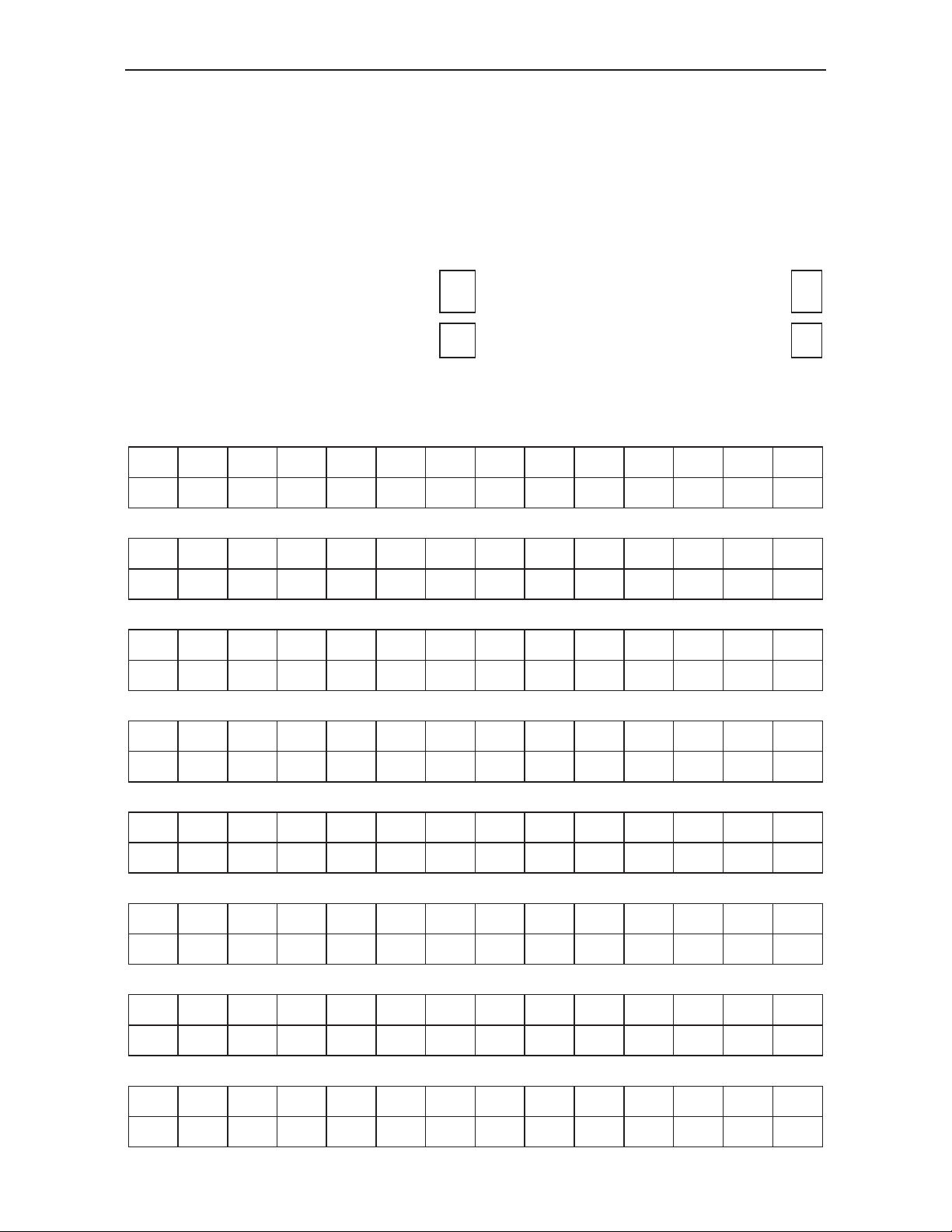
Message labels for the PD138 may be factory-printed at no charge, or
field-printed using a laser printer & clear self-adhesive labels. FactoryPrinted labels may be ordered at any time by completing the form below.
Horizontal mounting labels available, see page 10 for sample.
Make copies of this page for additional message labels.
Please include label with my
order.
Vertical Mounting
2 lines, 14 characters per message
I have the PD138, please send
ASAP.
Horizontal Mounting
2 lines, 11 charactersper message
Message 1
Message 2
Message 3
Message 4
Message 5
Message 6
Message 7
Message 8
33
Find Quality Products Online at: [email protected]
www.GlobalTestSupply.com
Page 34
PD138 Minimux® II Temp & Process Scanner Instruction Manual
MOUNTING DIMENSIONS
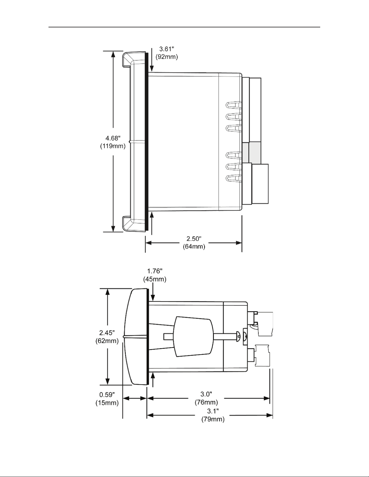
Figure 3. Case Dimensions – Side View
Figure 4. Case Dimensions – Top View
34
Find Quality Products Online at: [email protected]
www.GlobalTestSupply.com
Page 35

PD138 Minimux® II Temp & Process Scanner Instruction Manual
NOTES
35
Find Quality Products Online at: [email protected]
www.GlobalTestSupply.com
Page 36

PD138 Minimux® II Temp & Process Scanner Instruction Manual
LIM138_C
SFT053 Ver 1.0 & up
10/15
Find Quality Products Online at: [email protected]
www.GlobalTestSupply.com
 Loading...