

Page 1
PROVU Option Card Assembly Instructions
Hazardous voltages exist within enclosure.
Only trained service personnel should perform
installation and service.
Warning
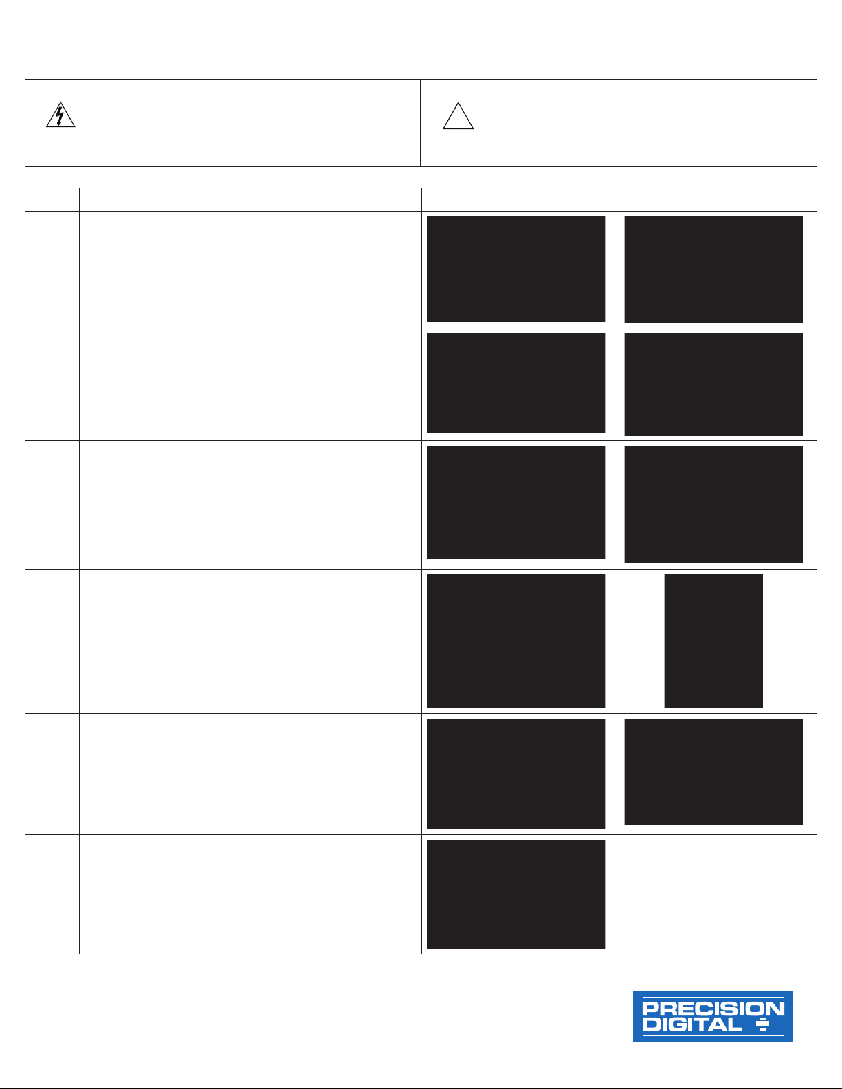
Step Description Illustration (a-b)
1
2
Disconnect power and signal from the meter prior
to performing the upgrade procedure below.
Position meter as shown on the first illustration to the
right and follow steps below:
Remove screw terminal plugs.a.
Using a medium Phillips screwdriver, remove theb.
2 retaining screws.
Remove back cover.a.
Remove the main board. Hold board by theb.
edges and firmly pull out of the enclosure.
Display board is attached to the enclosure. Doa.
not remove this board.
!
Caution
To Prevent damage to electronic components
caused by electrostatic discharge, a grounding
strap should be worn when performing the upgrade
procedure below.
3
4
5
6
Position the meter with the terminal connectorb.
diagram label on top as shown.
NOTE: Verify that J7 connector is at the top and the
J8 connector at the bottom of display board.
Insert the option board and main boarda.
simultaneously, with the option board going into
the top slot (seat into J7 connector) and the main
board going into the bottom slot (seat into J8
connector).
Ensure that both boards are fully seated.b.
When necessary knock out back cover tabs ina.
order to accommodate the additional board
connector headers. Then install the back cover
and secure with the 2 retaining screws.
Install all screw terminal plugs, includingb.
additional plugs supplied with kit.
Affix the new terminal connector diagram label.a.
Option
Card
Main
Board
LIM1102_B 06/09
Find Quality Products Online at: [email protected]
www.GlobalTestSupply.com
 Loading...