

Precision Digital MOD-PD2LHRB1, MOD-PD2LHYB1, MOD-PD2LHBB1, MOD-PD2LHGB1, MOD-PD2LH5CB1 User manual
...Page 1
FEATURES
• Light with Horn Mounted & Wired to Helios
• Single Lights Available in Red, Green, Yellow, Blue, or White
• Units with One of Five User Selectable Lights Available
• Units with Three Layered Lights Available
• Light / Horn Powered Directly from Helios
• Light / Horn / Reset Button Mounted and Pre-Wired to Helios
• Light / Horn Programmable for Variety of Reset Functions, Including:
• Silence Horn at Any Time
• Light Stays on Until Alarm Clears
• Light Can Be Wired to Flash (Not Available on MOD-PD2LH5CB1) or Stay Steady On
• IP 65 Rated
• 85 dB Horn
• Operates from -5 to 40°C (23 to 104°F)
PRECISION DIGITAL CORPORATION
MOD-PD2LH Series
Light / Horn Accessory for Helios Meters
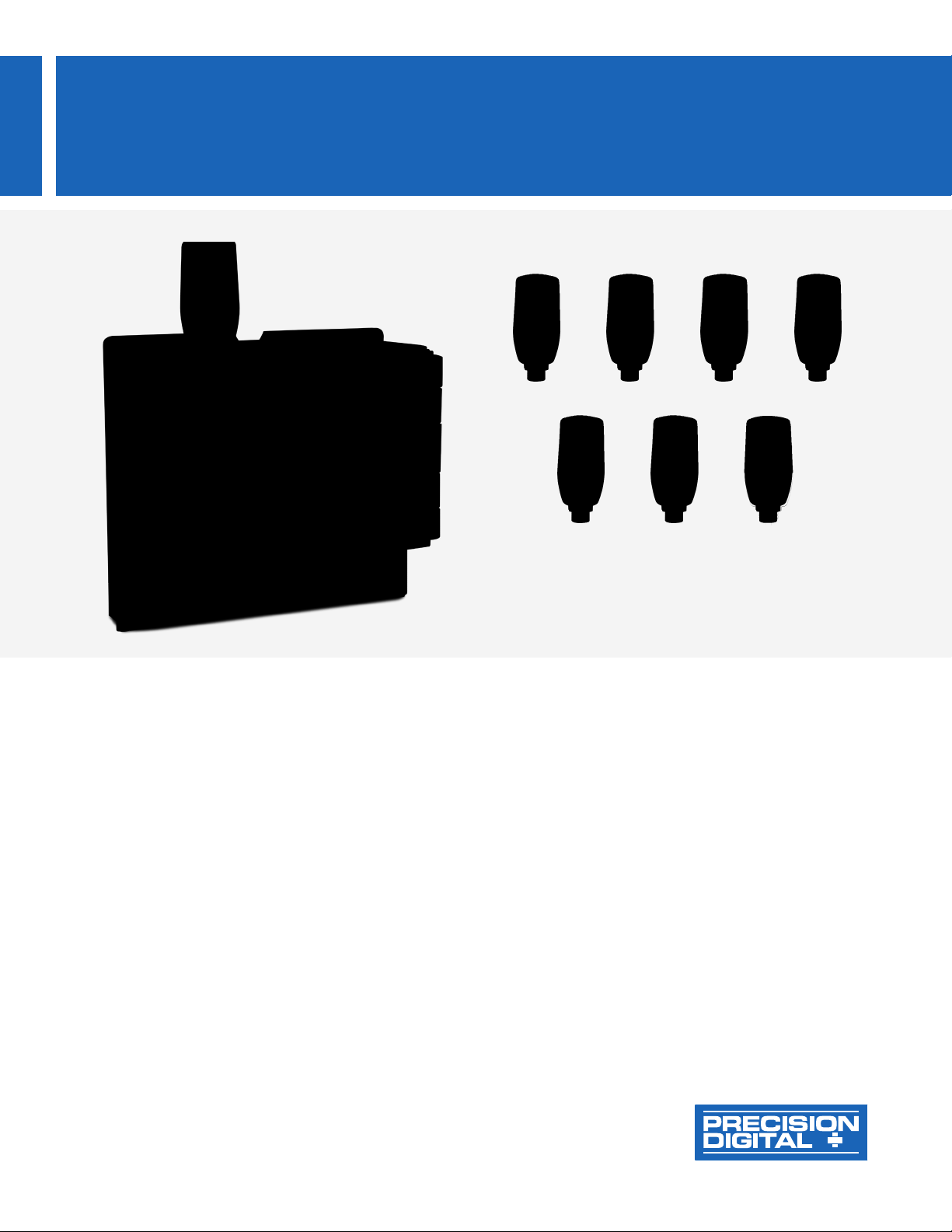
Helios Meter Shown with MOD-PD2LHRB1
Red Light / Horn and Reset Button.
Meter Sold Separately.
5 Colors 3 Layered
Colors
White
Red Green Yellow Blue
Find Quality Products Online at: [email protected]
www.GlobalTestSupply.com
Page 2
MOD-PD2LH Series Light / Horn Accessory for Helios Meters
M22 x 1.5
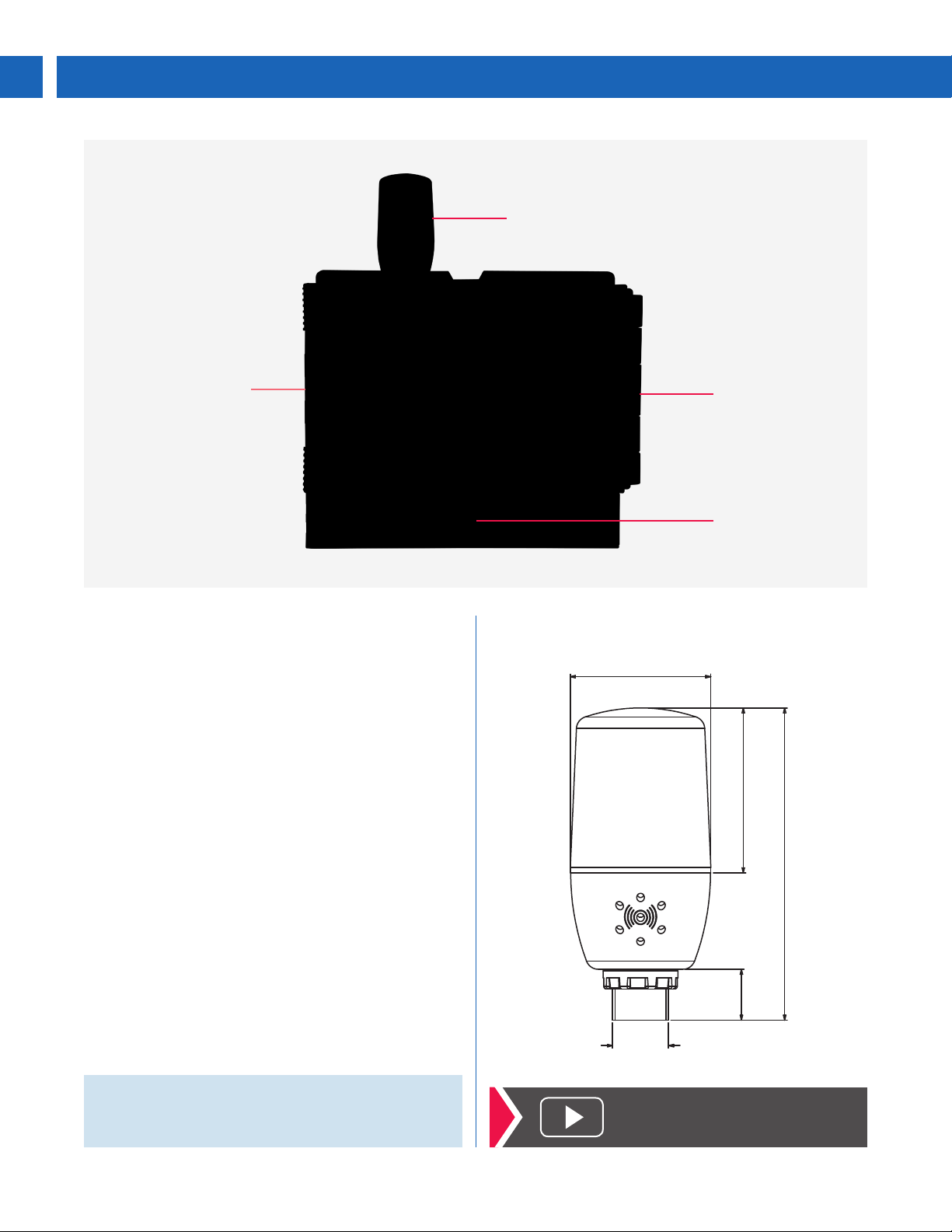
Helios Meter Shown with
MOD-PD2LHRB1
Red Light / Horn and
Reset Button.
Meter Sold Separately.
-5 to 40 °C
Operating
Temperature
Red Light
with 85 dB Horn
NEMA 4X / IP65
Reset Button
(9 Labels Provided)
OVERVIEW
The Helios c an be provided with an optional light(s) with
built-in 85 d B horn that comes mounted an d wired to the
instrument or a s separate items to be mounte d as the user
desires. Meter i s sold separately. The MOD -PD2LH Serie s
is available in three dif ferent light confi gurations. The first
option is a fact or y or dered L ight / Ho rn w ith a c olo r of eith er
red, green, yellow, blue, or whi te. The sec ond option is a
Light / Horn t he user determine s the light col or (red, green,
yellow, blue or white) by connecting the ap propriate wire.
The third opti on is a Li ght / Ho rn w ith re d, yellow, and green
layers the user can turn on independently.
The MOD-PD2LH can be powered from the Helios’s
200 mA tr ansmitter power supply with eno ugh power left
over to drive most transmitters.
The light(s) and horn can be controlled independently
of each other via separate relays on the Helios. These
relays can be programmed for automatic or manual reset
action to satisfy a wide variety of audible and visual alarm
applications. The light can be programmed to flash (not
available on MOD-PD2LH5CB1) or stay steady-on.
The Light / Hor n and Res et But ton do n ot af fec t the H eli os’s
NEMA 4X rating, but do void its UL approval.
DIMENSIONS
Units: Inches (mm)
Ø 2.2
(55)
2.6
(65)
4.8
(122)
0.8
(20)
Note: The Light / Horn accessory is powered from the 200 mA
transmitter power supply, so when this is installed, the meter’s
transmitter power is downgraded from 200 mA. See Transmitter
Power Supply specication on page 6 for details.
2
Find Quality Products Online at: [email protected]
www.GlobalTestSupply.com
Click here to watch the
Light / Horn Video
Page 3
MOD-PD2LH Series Light / Horn Accessory for Helios Meters
APPLICATIONS
There are a wide variety of ways these Light / Horn devices can be controlled by the Helios's four relays to satisfy visual and
audible alarm applications. Please feel free to contact tech support to discuss your particular application. The following examples
illustrate some typical applications.
MOD-PD2LH Models
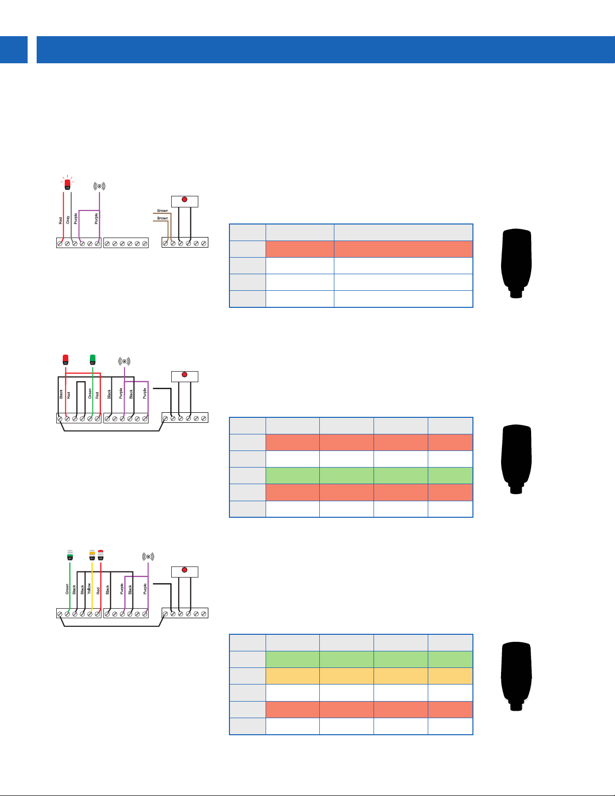
The MOD-PD2LH models are the simplest devices in the Series and are made up
of a single-color light and horn. A typical way to use the MOD-PD2LH is to program
Reset Button
the Helios so the horn can be silenced at any time via the Reset Button or F3 front
panel button on the Helios, and light to reset automatically when the alarm clears:
To Black
Wire on
Light Cable
SIGNAL
3 41 2 5
P- COMP+ V+ mA+
F4
Reset Button
SIGNAL
3 41 2 5
P- COMP+ V+ mA+
F4
RELAY2RELAY1
436521
C
NO
NONCC NONCC
NC
Note: Un less othe rwis e speci ed, this M OD is shipped
wired in the above fashion.
RELAY2RELAY1
436521
C
NO
NONCC NONCC
NC
Note: Un less othe rwis e speci ed, this M OD is shipped
wired in the above fashion.
RELAY4RELAY3
436521
NCC
NO
RELAY4RELAY3
436521
NCC
NO
6
Relay Connected to Default Reset Mode
1 Flashing Light
(1)
Auto reset
2 Horn Silence with Reset Button at any time
3 User Device As user desires
4 User Device As user desires
1. Light ca n be wired to ash or stay s teady on.
MOD-PD2LH5CB1
The MOD-PD2LH5CB1 shows one color at a time and the light color (red, green,
yellow, blue or white) is determined by which wires are connected to power through
the Helios's relays. A typical application for the MOD-PD2LH5CB1 might involve
lighting up the red light to indicate low and high alarms using the Helios's four
internal relays:
6
Relay Purpose Range Light/Horn Action
1 Low alarm < 199 Red light Auto
3 Low alarm < 199 Horn Latch
2 All OK 200 to 500 Green light Auto
2 High alarm > 500 Red light Auto
4 High alarm
> 500 Horn Latch
MOD-PD2LH3LCB1-RYG
The MOD-PD2LH3LCB1-RYG can light up red, yellow or green bands as
To Black
Reset Button
Wire on
Light Cable
RELAY2RELAY1
436521
C
NO
NONCC NONCC
NC
Note: Unless otherwise speci ed, this MOD is shipped
wired in the above fashion.
Find Quality Products Online at: [email protected]
RELAY4RELAY3
436521
NCC
NO
SIGNAL
3 41 2 5
P- COMP+ V+ mA+
F4
determined by which wires are connected to power through the Helio's relays. A
typical application for the MOD-PD2LH3LCB1-RYG (and the default factory setting)
might involve lighting up the green light to indicate everything is OK, the yellow light
to indicate a High warning, and the red light to indicate a High alarm. The Horn will
6
also sound at both the Warning and High alarms and can be manually reset at any
time with the front panel reset button:
Relay Purpose Range Light/Horn Action
1 All OK < 199 Green light Auto
2 Warning 200 to 500 Yellow light Auto
3 Warning 200 to 500 Horn Latch
2 High alarm > 500 Red light Auto
4 High alarm
> 500 Horn Latch
3
www.GlobalTestSupply.com
Page 4
MOD-PD2LH Series Light / Horn Accessory for Helios Meters
CONNECTIONS
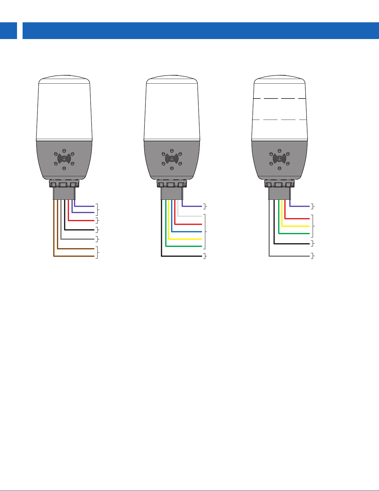
PURPLE
PURPLE
RED
BLACK
GRAY
BROWN
BROWN
Horn
Red LED
Steady On
Flashing
Power
MOD-PD2LH Models
Connections shown for a red light model.
For other MOD-PD2LH models, the red
wire is the color of the light. Connect the
red and black wires for a Steady On light
and red and gray wires for Flashing light.
PURPLE
WHITE
RED
BLUE
YELLOW
GREEN
BLACK
Horn
User
Selectable
LED
Minus
Supply
MOD-PD2LH5CB1
Connect the LED color to the plus supply
and the black wire to the minus supply to
turn the LED on. Be aware of limitations
for applications requiring different color
lights for different alarm conditions.
PURPLE
RED
YELLOW
GREEN
BLACK
Horn
Layered
LEDs
Minus
Supply
GRAY
Flashing
MOD-PD2LH3LCB1-RYG
Connect the LED color to the plus
supply for a Steady On light and LED
color and gray wires to the plus supply
for Flashing light. The black wire should
be connected to the minus supply.
4
Find Quality Products Online at: [email protected]
www.GlobalTestSupply.com
Page 5
MOD-PD2LH Series Light / Horn Accessory for Helios Meters
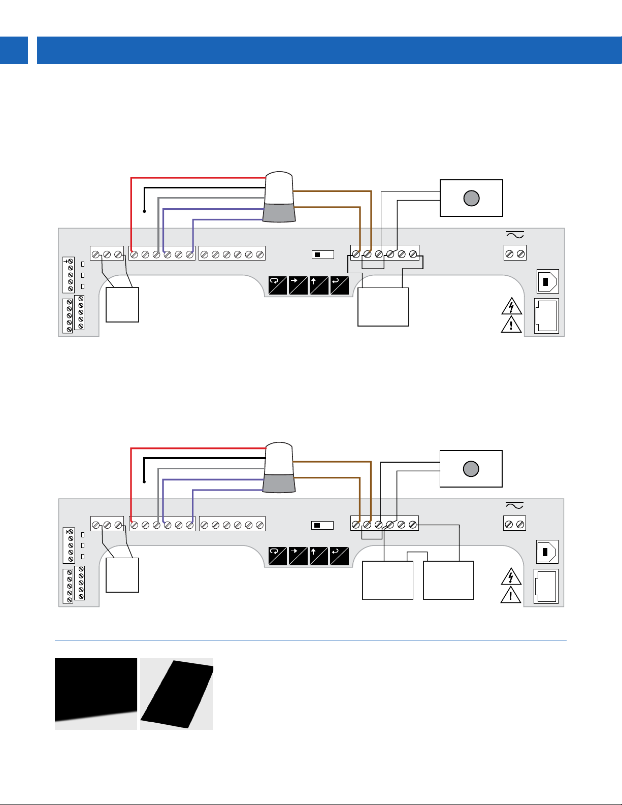
WIRING CONNECTIONS FOR MOD-PD2LH MODELS
Wiring Connections for Transmitter Powered by Helios
The Helios can be wired to power both the Light / Horn accessory as well as the transmitter input and isolated 4-20 mA output
as the following diagram illustrates.
• Connecting the light color
and gray wire makes
light flash
• Connecting the light color
and black wire makes
light steady on
MA OUT
21
R I-I+ NO
DO DO
DI
__ __
RS-485
PWR TX RX
DI
I1 I2 I3 I4+5
DIGITAL I/O
O1 O2 O3 O4 G
Blue, Green, Red, White, or Yellow (Light)
Black (Steady on)
Gray (Flashing Light)
Purple (Horn)
3
-
4-20 mA
Output
Powered
meter
by
C
RELAY2RELAY1
4
3
C NONCC
NC
+
NC
• Two isolated supplies available even
on 12/24 VDC input power models
• Removable terminal blocks
• Four (4) form C (SPDT) relays +
isolated 4-20 mA output option
• Digital Inputs and Outputs +
RS485 serial communication
Purple (Horn)
6521
NO
Light/
Horn
Beacon
Brown (Power)
Brown (Power)
Front Panel
Reset Push Button
P- COMP+ V+ mA+
+
F3
Meter provides
163 mA to power
the transmitter
when light/horn
option is installed
SIGNAL
3 41 2 5
F4
6
-
RELAY4RELAY3
4
3
6521
NCC
NO
MENU RIGHT UP ACK
MENU
RESET
F1
P+/P-
24V 10V 5V
F2
MAX
ENTER
+
POWER
-
21
USB
M-LINK
1
2
3
4
5
6
7
8
Wiring Connections for Transmitter Powered by External Source
Transmitters and sensors that require more than 163 mA must be powered by an external power source, such as the PDA1 024
as the following diagram illustrates.
• Connecting the light color
and gray wire makes
light flash
• Connecting the light color
and black wire makes
light steady on
Blue, Green, Red, White, or Yellow (Light)
Black (Steady on)
Gray (Flashing Light)
Purple (Horn)
Purple (Horn)
Light/
Horn
Beacon
Brown (Power)
Brown (Power)
Front Panel
Reset Push Button
DO DO
DI
__ __
RS-485
PWR TX RX
DI
I1 I2 I3 I4+5
O1 O2 O3 O4 G
MA OUT
21
3
-
4-20 mA
Output
Powered
meter
by
C
NC
+
• Two isolated supplies available even
on 12/24 VDC input power models
• Removable terminal blocks
• Four (4) form C (SPDT) relays +
isolated 4-20 mA output option
• Digital Inputs and Outputs +
RS485 serial communication
R I-I+ NO
DIGITAL I/O
RELAY2RELAY1
4
3
C NONCC
NC
P- COMP+ V+ mA+
F3
Power Supply
SIGNAL
3 41 2 5
F4
-
PDA1024
24 V External
+
6
requiring more
+
Transmitter
than 163 mA
-
RELAY4RELAY3
4
6521
NO
3
6521
NCC
NO
MENU RIGHT UP ACK
MENU
RESET
F1
P+/P-
24V 10V 5V
F2
MAX
ENTER
+
POWER
-
21
USB
M-LINK
1
2
3
4
5
6
7
8
RESET BUTTON LABELS
The Light / Horn accessory comes with 9 pre-printed message labels the user can
afx under the red button: RESET, BATCH, ACK, TARE, SILENCE, STOP, START,
PAUSE, START/STOP
5
Find Quality Products Online at: [email protected]
www.GlobalTestSupply.com
Page 6
MOD-PD2LH Series Light / Horn Accessory for Helios Meters
PRECISION DIGITAL CORPORATION
SPECIFICATIONS
Recommended for these Helios Models: PD2-6000,
PD2-6001, PD2-6100, PD2-6200, PD2-6300, PD2-6400,
PD2-7000. When ordered on other Helios Models user may
need to re-wire Light and Horn accessory.
ORDERING EXAMPLE
Order meter and MOD-PD2LH as separate items:
Item Description
1 Helios Meter with 2 or 4 Relays
2 MOD-PD2LH Light / Horn and Reset Button Mounted and Wired to Helios
Light Colors: MOD-PD2LH Models: Red, green, yellow,
blue, or white. MOD-PD2LH5CB1: User selectable: red,
green, yellow, blue, white. MOD-PD2LH3LCB1-RYG: 1 layer
ORDERING INFORMATION
each of red, yellow, green (consult factory for other colors)
Light Action: Can be wired to flash (not available on
MOD-PD2LH5CB1) or stay steady on
Horn: 85 dB
Rating: IP 65
Light / Horn Independence: Light and horn can be
controlled via separate inputs
Power Requirement: No additional power required when
installed in Helios. When mounted remote: 24 VDC
Transmitter Power Supply: The Helios's internal transmitter
power supply is downgraded from 200 mA when it powers
the Light / Horn. T o determine the total downgrade, add the
currents for the light(s) being used and the horn if used. If
more power is needed, then consider the PDA1024-01.
MOD-PD2LH and MOD-PD2LH5CB1 Models:
Color Downgraded by Color Downgraded by
Red 17 mA Blue 15 mA
Green 15 mA White 42 mA
Yellow 23 mA Horn 20 mA
Example: 17 mA (Red Light) + 20 mA (Horn) = 37 mA total current
downgrade from the 200 mA supply. Left over current = 163 mA
MOD-PD2LH3LCB1-RYG:
Downgraded by each color that is turned on and the horn
Color Downgraded by Color Downgraded by
Red 34 mA Yellow 33 mA
Green 29 mA Horn 38 mA
Example: 33 mA (Yellow Light) + 38 mA (Horn) = 71 mA total current
downgrade from the 200 mA supply. Left over current = 139 mA
Reset / Silence Button: NEMA 4X; mounted and wired to
F4 terminal on Helios
Reset Button Labels: The Light / Horn accessory comes
with 9 pre-printed message labels the user can affix under
the red button: RESET, BATCH, ACK, TARE, SILENCE,
STOP, START, PAUSE, START/STOP
Model Description
MOD-PD2LHRB1
MOD-PD2LHGB1
MOD-PD2LHYB1
MOD-PD2LHBB1
MOD-PD2LHWB1
MOD-PD2LH5CB1
MOD-PD2LH3LCB1-RYG
PDA-BUTTON1R Reset Button
PDA-LHR Red Light / Horn
PDA-LHG Green Light / Horn
PDA-LHY Yellow Light / Horn
PDA-LHB Blue Light / Horn
PDA-LHW White Light / Horn
PDA-LH5C
PDA-LH3LC-RYG
PDA1024-01 24 VDC Power Supply for DIN Rail
Notes
1. Specify MOD-PD2LH model as a separate item on the order for the Helios to order
the Light / Horn accessory installed and wired. Meter is sold separately.
2. Specify PDA-LH model to order the Light / Horn to be mounted by the user.
3. Specify PDA-BUTTON1R to order Reset Button to be mounted by the user.
Red Light / Horn / 1 Reset Button
Mounted and Wired to Helios
Green Light / Horn / 1 Reset Button
Mounted and Wired to Helios
Yellow Light / Horn / 1 Reset Button
Mounted and Wired to Helios
Blue Light / Horn / 1 Reset Button
Mounted and Wired to Helios
White Light / Horn / 1 Reset Button
Mounted and Wired to Helios
Light / Horn with User Choice of Red,
Green, Yellow, Blue or White Light,
Reset Button, Mounted and Wired to
Helios
Light / Horn with Red, Yellow, Green
Light Layers, Reset Button, Mounted
and Wired to Helios
Light / Horn with User Choice of Red,
Green, Yellow, Blue or White Light
Light / Horn with Red, Yellow, Green
Light Layers
Light / Horn Mounting Connection: M22
Hole Sizes: Light / Horn: 0.875" (22 mm);
Reset Button: 0.630" (16 mm)
Cable Length:
Approvals: Installation of the Light / Horn accessory voids the
Helios’s UL approval. Helios’s NEMA 4X rating is not affected.
Operating Temperature Range: -5 to 40°C (23 to 104°F)
WARNING
Cancer and Reproductive Harm - www.P65Warnings.ca.gov
3.28 feet (1 meter)
Disclaimer
The information contained in this document is subject to change without notice. Precision
Digital Corporation makes no representations or warranties with respect to the contents
hereof, and specically disclaims any implied warranties of merchantabilit y or tness for
a particular purpose.
©2019 Precision Digital Corporation. All rights reserved.
LIMMODPD2LH_A 03/19
Find Quality Products Online at: [email protected]
www.GlobalTestSupply.com
 Loading...