

Precision boilers FPS-31-20, FPS-31-15, FPS-39-25, FPS-39-20, FPS-39-30 Installation And Operating Instruction
...
Installation and Operating Instruction
FIRED STEAM BOILER
Model FPS
With
Power Burners
FOR YOUR SAFETY
This product must be installed and serviced by a professional service technician or gas/oil
supplier, qualified in steam boiler installation. Improper installation and/or operation could
cause serious injury or death. Improper installation and/or operation will void the warranty. Do
not store or use gasoline or other flammable vapors and liquids in the vicinity of this or any
other appliance.
1

WARNING
Improper installation, adjustment, alteration, service or maintenance can cause injury or
property damage. Read the manual thoroughly. For assistance or additional information consult
a qualified installer, service agency or the gas/oil supplier.
WHAT TO DO IF YOU SMELL GAS
Do not try to light any appliance.
Do not touch any electrical switch; do not use any phone in your building.
Immediately call your gas supplier from a neighbor’s phone. Follow the gas supplier’s
instructions.
If you cannot reach your gas supplier, call the fire department.
I M P O R T A N T
These instructions Are Intended as a Guide for the Installing Contractor and as a Reference for
the Operator, Owner and Serviceman
RETAIN THESE INSTRUCTIONS NEAR THE EQUIPMENT FOR READY REFERENCE
The instructions contained in this manual are intended as a guide only and do not supplant any
National, State or Local Codes.
This unit must be installed in accordance with those installation regulations in force in the local
area where the installation is to be made. Local regulations shall be carefully followed in all
cases. Authorities having jurisdiction shall be consulted before installation is made.
PRECISION has a commitment to product improvement and provides a continuing quest for the
highest standards of product performance. In pursuing this policy of continuous development
of products, the Manufacturer reserves the right to vary any details in this manual without
notice.
2

TABLE OF CONTENTS
I. GENERAL INFORMATION…………………………………………………………….……… 4
A. Introduction …………………………………………………………………………….…… 4
B. Warranty ………………………………………………………………………………….….. 4
C. Engineering Assistance ………………………………………………………………... 4
II. INSTALLATION …………………………………………………………………………………… 6
A. Uncrating……………………………………………………………………………………… 6
B. Placement………………………………………………………………………………….…. 6
C. Piping Connections………………………………………………………………………. 6
D. Electrical Connections………………………………………………………………….. 7
E. Fuel Connections………………………………………………………………………….. 7
GAS…………………………………………………………………………………………….…. 7
OIL…………………………………………………………………………………………….….. 9
F. Flue…………………………………………………………………………………………….…. 10
G. Combustion Air. …………………………………………………………………………... 11
III. START-UP ………………………………………………………………………………………….... 11
A. Pre-Startup Checks……………………………………………………………………….. 11
1. Piping Connections……………………………………………………………….…. 11
2. Pumps……………………………………………………………………………………... 11
3. Electrical …………………………………………………………………………………. 11
4. Combustion Air………………………………………………………………………... 12
5. Gas…………………………………………………………………………………………... 12
6. Oil…………………………………………………………………………………………….. 12
B. Filling the System…………………………………………………………………………... 12
C. Control Settings……………………………………………………………………………... 12
1. Controller………………………………………………………………………………... 12
2. High Limits……………………………………………………………………………….. 12
3. Low Water Cut-Off…………………………………………………………………… 12
D. Burner…………………………………………………………………………………………….. 12
1. Preparation for Startup – All fuels………………………………………….... 12
2. Startup……………………………………………………………………………………… 13
a. GAS BURNER………………………………………………………………………. 13
b. OIL BURNER……………………………………………………………………….. 13
IV. OPERATION AND MAINTENANCE………………………………………………………… 14
A. Operation……………………………………………………………………………………….. 14
B. Maintenance ………………………………………………………………………………….. 14
3

I. GENERAL INFORMATION
IMPORTANT WARNING
The Model FPS Boiler shall be installed according to the procedures detailed in this manual, or
the PRECISION warranty may be voided. The installation must conform to the requirements of
the local jurisdiction having authority, and to the latest edition of the National Fuel Gas Code,
ANSI Z223.1. Any modifications to the Boiler or its gas/oil controls may void the warranty. If
field conditions require modifications, consult the Factory.
A. INTRODUCTION
This manual supplies information on the application, installation and operation of Model
FPS – (Firetube) Steam Boiler. Review all application and installation procedures
completely before proceeding with the installation. Consult the PRECISION Factory, or
local Factory Representative, with any problems or questions regarding this equipment.
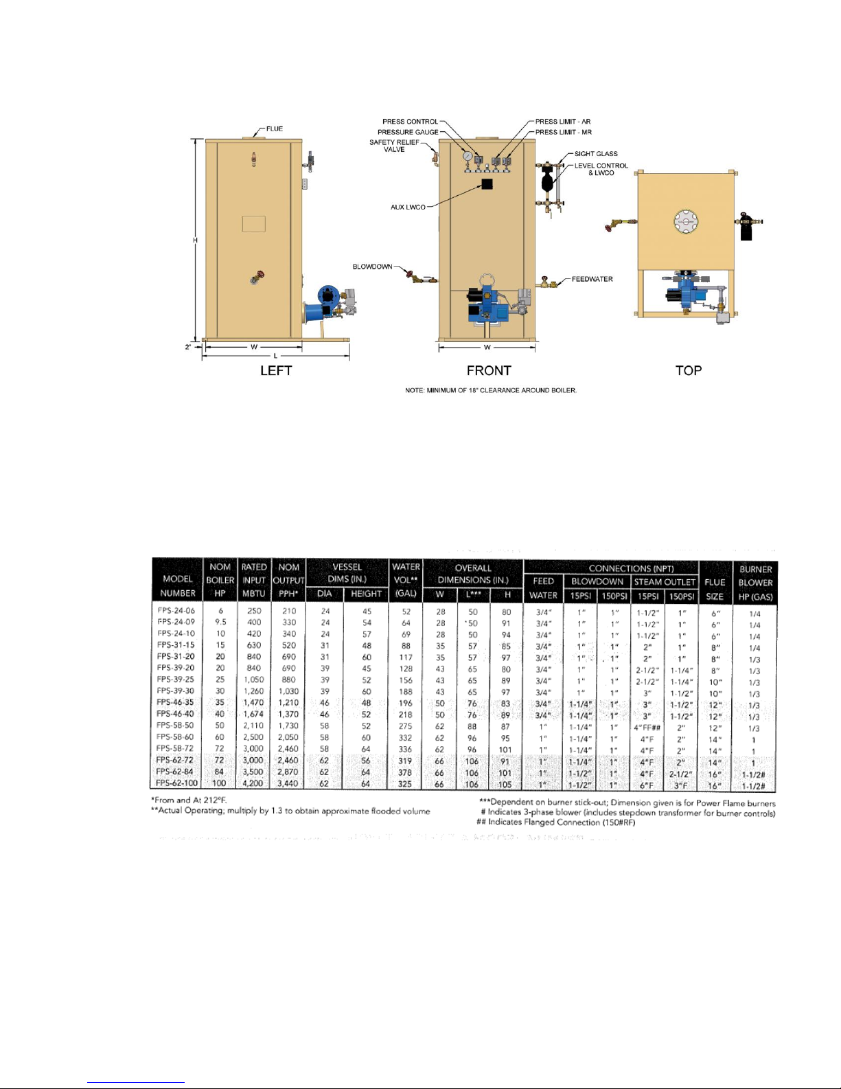
Experience has shown that improper installation causes most operating problems. The
FPS models are offered in the basic configuration shown in Figure 1 and Table 1.
B. WARRANTY
PRECISION Fired Steam Boilers are covered by a limited warranty. A copy of the
warranty is included in the back of this manual. Make all warranty claims to an
authorized PRECISION Representative or directly to the Factory. Claims must include the
unit serial number, model number (per the name plate) and installation date. Shipping
and labor costs are not included in the warranty coverage.
Some accessory items may be shipped in separate packages. Verify receipt of all
packages listed on the packing slip. Inspect everything for damage immediately upon
delivery, and advise the carrier of any shortages or damage. File any such claims with
the carrier. The carrier, not the shipper, is responsible for shortages and damage to the
shipment, whether visible or concealed.
C. ENGINEERING ASSISTANCE
Consult the Representative or Factory regarding any questions or problems which may
come up involving the specification, installation or operation of PRECISION equipment.
An experienced engineering staff is ready to assist in assuring their proper application
and performance.
4
5

II. INSTALLATION
A. UNCRATING
1. Care must be given not to damage controls or to deform the unit’s casing during
remove of the crate.
2. When using pry bars or fork lifts, be certain to support the unit on the shipping
skids or the channel base.
3. Storage – Electrical equipment can be damaged if exposed to adverse weather.
The unit should be stored inside. The electrical panel and controls must be
covered with plastic throughout all construction to avoid accumulation of dust
and moisture on the controls and other components.
B. PLACEMENT
1. Provide a firm, level foundation for the unit. Standard fired units are not suitable
for placement on combustible flooring.
2. Leave a permanent space of 18 inches on the sides and rear, and 24 inches on
the front for burner maintenance.
3. Be sure to keep the burner and controls covered at all times while work is in
progress.
CAUTION: DO NOT USE THE UNIT’S HOUSING TOP FOR SCAFFOLDING!!
C. PIPING CONNECTIONS
NOTE: Refer to applicable dimensionable drawing (DD) appendixed to this manual.
1. Boiler piping connections and valves MUST comply with state and local codes, in
addition to compliance with ASME piping requirements.
2. Install the safety valves(s) on the connection(s) provided. Plumb the safety valve
outlet full size to the floor drain for low pressure boilers, or to a safe point of
discharge for high pressure boilers. When two or more valves are used, discharge
lines may be manifolded proved unions are included for disassembly and the
common discharge pipe size must be greater or equal in area to the total are of all
safety valve outlets combined. Check local codes for proper safety valve discharge
piping.
3. Connect the feedwater supply to the feedwater valve train as shown on the DD.
CAUTION: Do not oversize feedwater piping and valves on Steam Boilers, as this
may result in severe pressure fluctuations during feedwater cycles if the fill rate is
too rapid.
6

4. Pipe both the bottom blowdown, and surface blowoff (if provided) to a nearby
drain (low pressure Boilers) or to a blowdown receiver (Boilers greater than 15
psi). Check compliance with local codes. Be sure to provide a low point drain to
enable complete draining of the Boiler.
D. ELECTRICAL CONNECTIONS
CAUTION: The Boiler must be electronically grounded in accordance with the most
recent edition of the National Electrical Code, ANSI/NFPA 70. Do not rely on the gas or
water piping to ground the metal parts of the Boiler. The use of plastic pipe or
dielectric unions may isolate the Boiler electrically. Service and maintenance
personnel may be standing on wet floors and could be severely shocked by an
ungrounded Boiler.
1. Check the Boiler wiring diagram (WD) for correct voltage, frequency, phase and
amperage of the required branch circuit. The branch circuit must be protected by a
properly sized circuit breaker or fused safety switch.
2. Electrically ground the unit per NEC and local code requirements using AWG #10
Cu wire minimum.
3. All field installed electrical safety devices and controls (draft switches, relays,
timers, pressure reset devices, etc.) can be connected as shown in the wiring
diagram designated “Field Interlock Provision”.
E. FUEL CONNECTIONS
NOTE: Also refer to the burner literature supplied as an appendix to this manual
relative to the actual burner supplied with your unit.
-GAS
NOTE: Contact your local gas service company to assure that adequate gas service is
available and to review applicable installation codes for your area. The gas line
pressure should be in the range of 5-14 ins WC.
1. Size the main gas line in accordance with Table 2. The figures shown are for
straight lengths of pipe at 0.2 ins. WC pressure drop, which is considere4d normal
for low pressure systems. Note that fittings such as elbows and tees will add to the
pipe pressure drop.
2. Refer to Figure 2 for details of gas piping. Mount any items of the gas train shipped
loose as shown. Install the main gas cock with drop leg upstream of the regulator
and automatic valves. The pilot line should be piped into the upstream tapping on
the main gas train shut-off cock.
7

8

NOTE: For ease of servicing we recommend the use of a union immediately upstream of
the main gas pressure regulator or combination gas valve/pressure regulator.
3. Install vent lines from main gas regulator (if used) and (if applicable) diaphragm
gas valve. Vent line should be run to the outside of the building, terminating clear
of windows or fresh air intakes. Outside termination of vent should have a screen
to prevent insects from building nests in vent pipe. The vent should terminate in a
manner which will preclude the possibility of water, dirt or other matter from
entering the line.
4. Test gas lines for leaks using soap solution. Your local gas service company may
wish to carry out or witness this test.
CAUTION: Gas pressure above 14 ins. WC may damage the standard diaphragm
gas shut-off valve. Do not exceed this value when pressure testing lines unless you
cap off the line upstream of the main gas cock and pilot take-off.
-OIL
CAUTION: Most oil burners supplied on Model FPS and TPS units are designed for use
with light grade fuel oils – commercial standard grades #1 or #2.
1. Prior to installation, it is recommended that all national, local and other applicable
codes be reviewed to ensure total compliance.
NOTE: A two pipe (separate suction and return line) system must always be used.
The fuel pump is pre-set at the Factory for use only with a two pipe system. The
pump warranty will be voided if a one pipe system is used with this burner. Rigid
pipe connected directly to the pump may cause excessive vibration. It is
recommended that the connection to the pump be of copper tubing, complete
with vibration dampening loop, on both suction and return lines. Do not use
Teflon tape. The pump warranty will be voided if Teflon tape is used.
2. Size the oil supply and return lines in accordance with the guidelines provided in
the fuel pump instructions appendixed to this manual. It is very important to
properly size the oil suction line and oil filter to provide fuel flow to the burner
without exceeding 10” suction pressure (vacuum) at the oil pump suction port. Use
copper tubing with flare fitting or iron pipe on all installations. Use ½” OD oil lines
whenever possible. All units must utilize the proper size and type of suction line oil
filters.
9

3. Refer to Figure 3 for details of oil piping. All field piped components must be
mounted in the proper order as shown with the proper direction of oil flow.
CAUTION: Oil supply pressure to the burner oil pump must not exceed 3 psi per
NFAA Codes.
NOTE: Do not install manual valves in the return line between the pump and the
tank unless required by a specific code. If a manual valve is required, an automatic
relief valve must be installed across the manual valve to ensure that oil will bypass
directly back to the tank in the event the manual valve is inadvertently left in the
closed position.
4. Before starting up the system, all appropriate air and oil leak tests should be
performed. Make certain that the tank atmospheric vent line is unobstructed.
F. FLUE
CAUTION: Jurisdictional authority relating to venting/flue requirements vary widely. In
order to make certain of compliance, the controlling authorities should be consulted.
10

1. Use positive pressure breeching material. Breeching should be short, straight and
full size. Horizontal runs over 10’ or over (2) elbows should be avoided. Runs
should pitch upward at least 1” per foot.
2. A full size barometric damper should be installed in the breeching to regulate the
drafts. After startup, check the damper and breeching by holding a match near the
edge of the damper. A correct installation will pull the flame with the burner
running.
G. COMBUSTION AIR
1. Provide fresh air to support combustion and to supply adequate location
ventilation.
NOTE: All fuels require approximately 10 cubic feet of standard air (sea level at
60 degrees) per 1000 BTU’s firing rate, for theoretical perfect combustion. In
actual practice, a certain amount of excess air is required to ensure complete
combustion, but this can vary substantially with specific job conditions. Additional
air is lost from the boiler room through barometric dampers, draft diverters and
similar venting devices. It is generally accepted that ½ square inch of free air
opening (for each gas or oil burner in the room) per 1000 BTU/hr firing rate will be
adequate.
2. After startup, test to assure a positive boiler room pressure with the Boiler
operating at 100% input.
CAUTION: Under no circumstances should a boiler room be under negative
pressure. If combustion air is ducted to the burner, make sure the duct size is
adequate to assure proper burner operation.
III. START-UP
A. PRE-STARTUP CHECKS
1. Piping Connections
Are they complete and correct?
2. Pumps
Are the feed pumps functional?
Is the motor rotation correct?
3. Electrical
11

Is the branch circuit power supply as required per the burner name plate?
Is the unit properly grounded?
4. Combustion Air
Is adequate fresh combustion available?
Is the breeching/stack open and unobstructed?
5. Gas
Is the gas supply available?
6. Oil
Is there adequate amount of oil in the tank?
Is the oil the proper grade?
B. FILLING THE SYSTEM
1. The system and the Boiler should be thoroughly flushed before start up.
2. Operate water column and level control drain/blowdown valves to assure that
these are thoroughly flushed and operate properly.
3. Before firing the unit, be sure the unit is filled to the proper water level.
C. CONTROL SETTINGS
1. Controller
This is the pressure sensing device which controls the operation of the burner. Set
the controller for the desired steam pressure.
2. High Limits
Set the high limit auto reset control approximately 10% above the setting of the
controller. Manual reset limits should be set approximately 5% above the auto
reset limit, but should not be set higher than 95% of the safety valve set pressure.
3. Low Water Cut-Off
This limit is always Factory-set. If additional units are field installed, manual reset
LWCO’s should be positioned below the automatic reset limit.
D. BURNER
IMPORTANT: Read the burner O&M manual (Appendixed to this manual) thoroughly
before attempting to start the burner.
CAUTION: Failure to properly follow the detailed start up instructions given in the
burner O&M manual may result in an explosion which could cause property damage,
injury, or loss of life.
12

1. Preparation for Start Up – All Fuels
a. Run an inspection of the tightness of all electrical connections and retighten as
necessary. This tightness inspection is vital because vibration during shipment
can often loosen electrical connections.
b. Set the burner control panel switch to the “OFF” position.
c. Turn the operating control down to its lowest setting.
d. Check fuses and replace as necessary.
e. Depress the flame safeguard programming control reset button.
2. Start Up
- GAS BURNER
a. Manually open and close the main gas shut off cock, leak test cock and pilot
cock to determine that they operate freely. Open all three cocks. (Reset low
gas pressure switch if supplied).
b. Set the main power switch and burner panel control switch to the “ON”
position. Wait 30 seconds and turn up the operating control to the desired
setting.
c. The burner blower motor will start and after a suitable prepurge period (this
will vary with the type of flame safeguard control supplied- but will usually be a
minimum of 30 seconds to a maximum of 90 seconds) the burner pilot will
light, after which the main flamewill be established.
d. When burning gas on a Combination Gas/Oil unit that has a blower motor
driven oil pump, open all oil line valves. Oil must circulate through the oil
pump, even when burning gas.
- OIL BURNER
a. Open all valves in oil lines
b. If pilot gas ignition system is supplied – open and close the pilot gas cock to
determine that it is operating freely. Open the pilot gas cock.
c. Set the main power switch and burner panel control switch to the “ON”
position. Wait 30 seconds and turn up the operating control to the desired
setting.
d. The burner blower motor will start. Depending upon the type of flame
safeguard system supplied, the fuel ignition system may energize within 1 or 2
seconds after the blower motor starts or could be as long as 90 seconds.
13

NOTE: For more detailed burner start-up information, refer to the burner
literature supplied as an appendix to this manual relative to the actual burner
supplied with your unit.
IV. OPERATION AND MAINTENANCE
A. OPERATION
1. When the operating controller calls for pressure, the burner blower motor will
start and after a suitable prepurge period (30-90 seconds approximately) the
burner pilot will light. (The unit performs its own safety check and opens the main
valve only after the pilot is proven to be lit). The main flame is then established.
2. The operating controller will control to the desired steam pressure. The
differential adjustment should be set at the highest value which will still provide
acceptable steam pressure variation. Two pressure controllers are supplied on hilo fired units, and a proportional controller is supplied on modulating burners.
3. An automatic reset pressure limit is supplied as standard on all modulating units.
4. A manual reset high limit is provided as standard equipment on all units. The
burner will automatically shut down whenever an over pressure condition occurs.
5. A manual reset low water cutoff is also provided as standard equipment on all
units. The low water cutoff automatically shuts off the burner whenever the water
level drops below the Factory set level in the upper part of the tank.
NOTE: Warranty does not cover any damage caused by lack of required
maintenance or improper operating practices.
B. MAINTENANCE
1. At startup and at least every six months thereafter, the pilot and main burner
flame should be observed for proper performance. (Refer to burner literature
supplied with this manual for detailed information).
2. Inspect the venting system for obstruction, leakage, and corrosion at least once
per year.
3. Keep Boiler area clean and free from combustible material, gasoline and other
flammable vapors and liquids.
4. Be certain all combustion air and ventilation openings are unobstructed.
5. The gas and electric controls installed on these Boilers are engineered for both
dependable operation and long life, but the safety of this equipment completely
depends on their proper functioning. It is strongly recommended that the basic
14

items be checked yearly by a competent service person and replaced as necessary.
The basic controls are:
a. Operating Control
b. Pilot Safety System
c. Automatic Electric Gas/Oil Valve(s)
d. Limit Controls
6. Low water cutoffs should be inspected every six months, including cleaning probes
and flushing floats.
7. Firebox inspections can be made by removing the burner. If repairs are required,
the entire firebox can be withdrawn from beneath the pressure vessel by use of
the (3) jacking eyes attached to the vessel’s lower flange.
15
 Loading...