

AMPLIFIERS
AMPLIFICATEURS
PA602
PA604
PA500D
INSTRUCTION MANUAL
LIVERT D’INSTRUCTIONS
INSTRUCTION MANUAL
PA602 | PA604 | PA500D
Overview
Introduction
Precision Acoustics would like to introduce our small footprint and big
power car audio amplifier product line. Keeping performance and
budget in mind, our engineers have delivered on maximum wattage for
minimum dollar! And knowing that showing off your gear is as important as being heard down the street, we were sure to pay equal attention on style and functionality. After all, we want you to have the ultimate car audio system. Precision Acoustics would like to thank you for
CAUTION
purchasing its products.
This device is a high power, audio
amplifier. Proper and careful usage
of this product will provide many
years of enjoyment. Being exposed
to very loud music can result in
temporary or permanent hearing
loss. Misuse or improper installation will shorten the life of your
product, and/or result in damage to
the vehicle electrical system.
Please ensure you read this manual completely for procedures on
how to properly install this unit.
Description
The brand new PA amplifier series is engineered to deliver powerful,
undistorted sound. Using proven MOSFET technologies and manufacturing processes such as surface mount components, we strive for
product reliability and strict standards in quality control. Our amplifiers
are driven through rigorous load tests to ensure they operate under the
most stressful of conditions. After all, we know you will!
MOSFET technology assures your amplifier satisfies the voltage and
current demands of today’s systems. And with ultra low distortion, they
will deliver clean, crisp sound to your speakers and subwoofers.
Stability is essential in delivering a clean output signal, especially when
your speaker system drops below normal impedance levels. Our
dynamic full-range Class AB amplifiers will operate safely into 2 ohm
loads, without causing distortion to get out of control. All while reproducing a wide frequency response.
Our ground-pounding Class D amplifiers will operate safely into 2 ohm
loads, and can be summed for those power hungry subwoofer systems.
Operating at these loads will generate lots of heat. So we’ve engineered the heat sink to dissipate that heat effortlessly, while keeping
your tunes pumping hard!
Professional setup of your audio system to get the right sound is an
absolute must. With tri-mode crossovers and continuously variable frequency control, you can tweak your system for optimum speaker performance. We LOVE a great sounding car audio system too!
INSTRUCTION MANUAL
PA602 | PA604 | PA500D
Features
PA602, PA604
• Class AB Circuitry - 2 ohm stable
• Surface Mount Technology
• MOSFET Power Supply
• Frequency response from 10Hz to 25KHz
• Low Level Input – variable up to 5 volts RMS
• Gold Plated Input & Output Terminals
• Tri-mode Crossover Selection - LPF / FULL / HPF
• Variable Crossover Control from 50 to 750Hz
• Quad Protection Circuitry - Short, Voltage, Overload and Thermal
• Protection Indicator
Features
PA500D
• Class D Circuitry – 2 ohm stable
• Surface Mount Technology
• MOSFET Power Supply
• Dual Amplifier Summing – master/slave
• Gold Plated RCA Connections
• Variable Low Pass Filter Control from 40-180Hz @ 18dB/oct
• Subsonic Filter from 10 to 50Hz
• Frequency response from 10 to 180Hz
• Low Level Input – variable up to 5 volts RMS
• Heavy Duty Terminal Block for Power Input & Speaker Output
• Quad Protection Circuitry - Short, Voltage, Overload and Thermal
• Protection Indicator
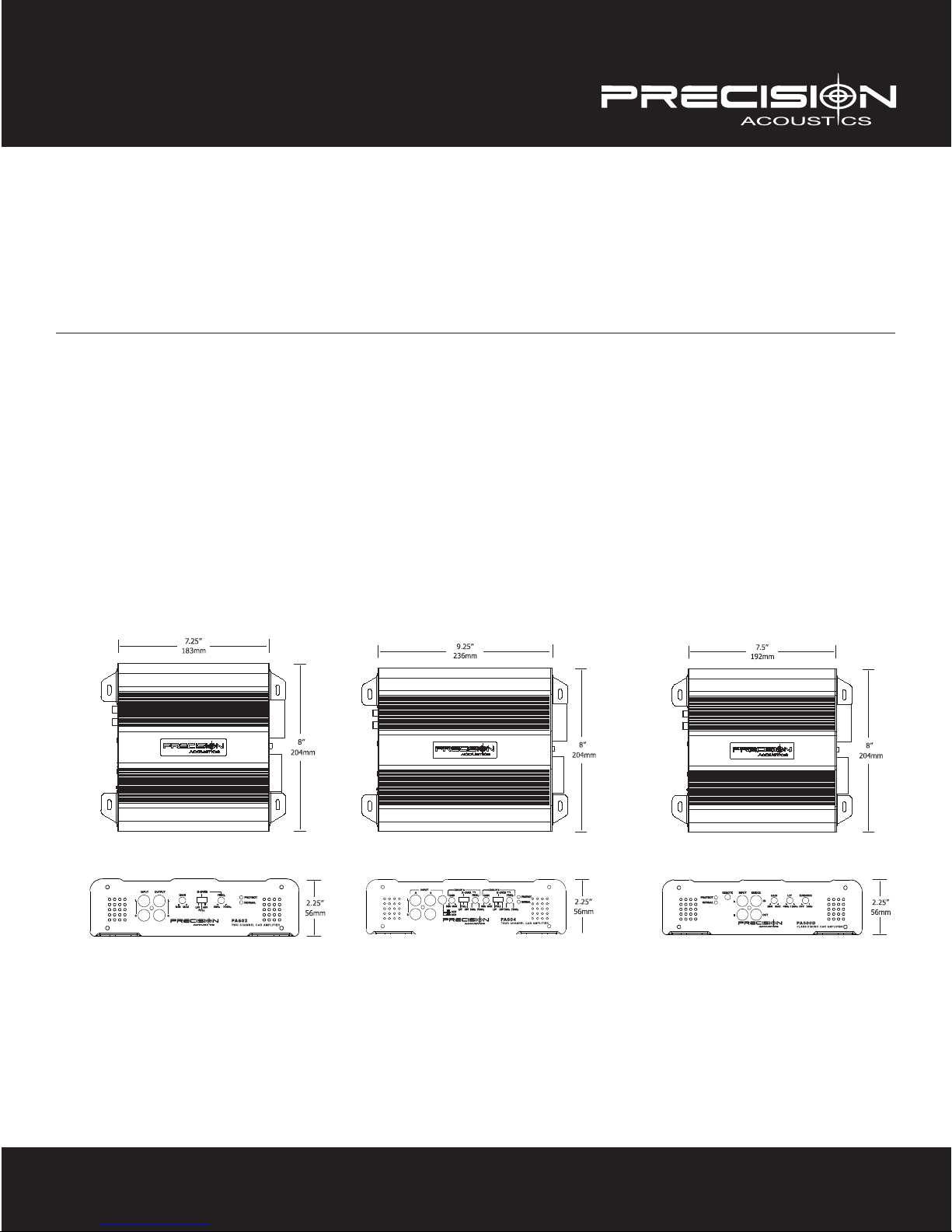
PA602 PA604 PA500D

INSTRUCTION MANUAL
PA602 | PA604 | PA500D
Installation
Precision Acoustics recommends professional installation of all its products. Should you choose to install this
product yourself, please read this manual carefully and refer to the instructions detailed below. Failure to do so
may result in poor product performance, premature or immediate malfunction, and potential damage to your
vehicle or its contents.
•When selecting a location to mount your amplifier, please ensure proper ventilation is considered. Areas
below seats or in trunks are suitable, so long as air flow is not restricted. Refrain from mounting your
amplifier upside down, as heat will not dissipate effectively, and can result in thermal shutdown or
component failure
•Mount your amplifier using 4 screws, preferably onto a piece of wood. If screwing into the body of the
vehicle, be sure to check for brake, fuel or electrical lines, as well as stay clear of the gas tank.
•Using a minimum of 8 gauge wire for PA602 / PA604, or a minimum of 4 gauge wire for PA500D, run a
power cable directly to the positive terminal of your battery to the ‘+12V’ terminal of your amp. A separate
fuse must be located within 18 inches of the battery to protect the vehicle from a potential short. Total up
the fuse ratings on your amplifiers to determine the fuse size required under the hood.
•Your amplifier should turn on only when ignition is activated. This can be accomplished by connecting an
18 gauge wire to the ‘trigger’ output on your head unit. If you are using an OEM radio, this will not be
available. You must locate a +12v switched circuit to achieve this.
•The ground path is equally important to the positive feed of your amplifier. Find or create a bare metal
spot on the vehicle’s chassis. Using as short a wire as possible, connect to the ‘GND’ terminal using the
same gauge wire as you did for power. The paint on the body must be removed to bare metal.
•If you’re using a low-level output signal from your head unit, ensure to use a high quality RCA cable to
prevent unwanted noise. It is preferred to use the side opposite to the power wire to run the RCA. Failure
to do so can introduce unwanted noise into the input signal which will be heard through your speakers.
•If your head unit doesn’t have RCA, a speaker level adapter would be used. For this, it is ideal to tap in on
the speakers closest to the amplifier location. Using regular 18 gauge speaker wire, take left and right
(both positive and negative) signals. Connect directly to the ‘hi-level’ input on your amplifier. Proper gain
settings are required to ensure undistorted sound.
•You have now completed the installation portion of your new amplifier. Please continue to the “Amplifier
Settings” section of this manual to properly configure your amp for maximum listening pleasure.

INSTRUCTION MANUAL
PA602 | PA604 | PA500D
Amplifier Settings
Gain Calibration
The gain control (input sensitivity) on this amp is not a volume control. It is designed to provide proper matching of various source units to this amplifier, and provides a reference to how much signal will be necessary to
reach maximum operating power. Correct settings will ensure safe operation for both your amplifier and
speakers.
•Start by turning the gain level to the “MAX” setting. This is the minimum level, far right.
•Next, turn up your head unit volume up to 75% of max volume. For example, if your digital volume control
goes to “50”, you would use the “40” level for this exercise.
•Last, slowly begin increasing the gain sensitivity ‘counter-clockwise until distortion becomes audible, and
then turn the gain back a notch. You have now properly set your input sensitivity.
Crossover Control
Your amplifier has been designed with an onboard crossover, or filter management system. How you configure
these settings will be dependent on the speakers you are connecting to the amplifier. The crossover circuit consists of two main settings: 1. Filter Type; 2. Frequency Adjustment.
The “filter type” is controlled by a “LPF, FULL, HPF” switch. The low-pass filter, LPF, will allow only low frequency information to pass on to the speakers. The opposite would be achieved using the HPF, high pass filter.
When no filter is required, the FULL setting would be selected, allowing all frequencies to pass.
For proper operation of some speakers, it is necessary to select the crossover point to which they will play. The
“frequency adjustment” setting allows you to accomplish this. In a LPF mode, only frequencies up to the
crossover point will play, with a gentle roll-off beyond that point. In HPF mode, any frequency above that point
will be heard, with those below being filtered away gradually.
Low Level Output
Rather than running a 2nd RCA for multiple amplifiers, the low level output offered on the PA602 will provide a
full-range signal to an additional amplifier. Simply run a shorter RCA from this amplifier to the next one in line,
such as your PA500D subwoofer amplifier. Fading capability will not be possible in this arrangement.
Subsonic Filter
Getting the most out of your amplifier is our goal. Having a subsonic filter in your subwoofer amplifier is going
to achieve just that. If you’re running a ported subwoofer system, it’s crucial that the output signal from your
amplifier doesn’t drop drastically below the tuning frequency. If that should happen, your subwoofer will feel as
if it’s in open air. The result, slow and permanent damage to the voice coil.
The subsonic filter found on our PA500D offers a continuously variable setting from of 10Hz to 50Hz. This will
ensure that sub-harmonics are dropped off quickly from your desired frequency. Proper setting of this filter will
help your subwoofer play cleaner, louder and with less distortion. Furthermore, your amplifier runs more efficiently by not wasting voltage and current on reproducing unwanted or damaging frequencies.

INSTRUCTION MANUAL
PA602 | PA604 | PA500D
Amplifier Settings
Master/Slave Bridging
The PA500D is capable of running in a Master/Slave configuration. This implies that two amplifiers can be ran
in sync to the same subwoofer voice coil, or subwoofer configuration. The result of which is twice the output
than what one amplifier could offer on the same load. Please note that each amplifier in this setup will see half
the load, meaning a 4 ohm woofer will net 2 ohms per amplifier. This is the minimum impedance which the
amplifier can support in this setup.
For configuring gain and crossover, you only need to adjust this on the master amplifier. The master amplifier
will be identified by which receives the input signal from your source head unit. There is no “master/slave”
switch as typically found on other amplifiers. To configure the amplifiers, you will run from “Bridge Out” on the
master to “Bridge In” on the slave. Please refer to the wiring illustrations in this manual for a configuration
diagram.
Protection Circuitry
This amplifier has been outfitted with protection circuitry against short, overload, low voltage and thermal
shut-down. In a functional state, the NORMAL LED glows solid and indicates “power on”. Should the amplifier
sense any fault in your speakers or subwoofers, it will flash to indicate a malfunction.
The PROTECT light will glow if the amplifier detects excessive heat, reverse polarity, short circuit or overload.
In this case, shut the power to the system and allow time for cooling to bring the amplifier back to a functional
state.
If the PROTECT light remains lit after cycling the power OFF then ON, internal damage to the amplifier may
have occurred. Please return the amplifier to the original place of purchase for inspection.
Fusing
Fusing your car audio system ensures effective protection against current overload. The PA500D has been engineered without a fuse, as establishing the proper fuse value is dependent on amplifier load. When running the
amplifier at 4 or 2 ohms, the recommended fuse is 40 amps. If running in a 4 ohm master/slave configuration,
an 80 amp fuse is required.

INSTRUCTION MANUAL
PA602 | PA604 | PA500D
Specifications
PA602 PA604 PA500D
Continuous Power
• 4 ohms (RMS) 65 x 2 65 x 4 320 x 1
• 2 ohms (RMS) 100 x 2 100 x 4 500 x 1
Bridged Power
• 4 ohms (RMS) 190 x 1 190 x 2
Maximum Power
• 4 ohms 130 x 2 130 x 4 640 x 1
• 2 ohms 200 x 2 200 x 4 1000 x 1
THD <0.03% <0.03% <0.08%
Signal to Noise Ratio >90db >90db >80db
Frequency Response 10-25KHz 10-25KHz 10-180Hz
Crossover HPF-FULL-LPF HPF-FULL-LPF LPF
• High Pass (HPF) 50-750Hz 50-750Hz n/a
• Low Pass (LPF) 50-750Hz 50-750Hz 40-180Hz
Speaker Impedance 2 ohms 2 ohms 2 ohms
Damping Factor 220 @ 4 ohm 200 @ 4 ohm 190 @ 4 ohm
Input Sensitivity 200mV – 5V 200mV – 5V 200mV – 5V
Dimensions 7.25” x 9” x 2” 9.25” x 9” x 2” 7.5” x 9” x 2”
Fuse Rating 30A 40A external (see "Fusing")
INSTRUCTION MANUAL
PA602 | PA604 | PA500D
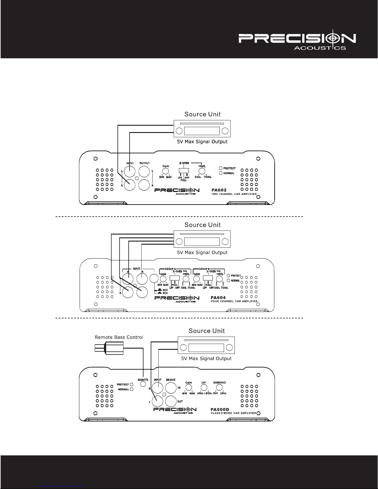
Installation – Signal Input

INSTRUCTION MANUAL
PA602 | PA604 | PA500D
PA602 – Wiring Configuration
Note: Use a minimum of 8ga power and ground on this amplifier.

INSTRUCTION MANUAL
PA602 | PA604 | PA500D
PA604 – Wiring Configuration
Note: Use a minimum of 8ga power and ground on this amplifier.

INSTRUCTION MANUAL
PA602 | PA604 | PA500D
PA500D – Wiring Configuration
Note: Use a minimum of 4ga power and ground on this amplifier. A 40 amp fuse is required.

INSTRUCTION MANUAL
PA602 | PA604 | PA500D
PA500D – Master/Slave Configuration
Note: Use a minimum of 4ga power and ground on this amplifier. A 80 amp fuse is required.

MANUEL DE L’UTILISATEUR
PA602 | PA604 | PA500D
Présentation Générale
Introduction
Precision Acoustics voudrait vous présenter à nos amplificateurs audio de
voiture de petite taille et puissance élevée. gamme d’amplificateurs. Gardant
en tête le rendement et le prix, nos ingénieurs vous offrent un wattage maximum pour un minimum d’investissement en argent! Sachant aussi que
montrer votre appareillage est tout aussi important que d’être entendu sur
la rue, nous nous sommes assurés de porter autant d’attention au style et
AVERTISSEMENT
Cet appareil est un amplificateur
de très grande puissance.
L’utilisation adéquate et soignée de
ce produit vous procurera de nombreuses années d’agrément.
L’exposition à la musique à un
niveau sonore très élevé
peut mener à la perte temporaire
ou permanente de l’ouïe. Une utilisation inappropriée ou une installation incorrecte réduiront la durée
de vie utile de votre produit et/ou
endommageront le système électrique de votre véhicule. Assurezvous de lire au complet ce manuel
pour connaitre les procédures sur
la façon d’installer correctement
cet appareil.
aux fonctionnalités. Après tout, nous voulons que vous ayez l’ultime chaine
de radio d’auto. Precision Acoustics désire vous remercier de vous être
procuré ses produits.
Description
Cette entièrement nouvelle gamme d’amplificateurs PA est conçue pour
produire une sonorité puissante et sans distorsion. Utilisant les technologies
éprouvées MOSFET et des processus de fabrication tel les composantes à
montage en surface, nous nous efforçons de vous offrir des produits fiables
en effectuant les contrôles de qualité les plus stricts. Nous faisons subir à
nos amplificateurs des tests de charge très rigoureux pour nous assurer
qu’ils puissent fonctionner sous les conditions les plus difficiles. Après tout,
nous savons que vous le ferez!
La technologie MOSFET vous assure que votre amplificateur répond aux exigences des systèmes d’aujourd’hui en matière de tensions et de courants.
Ils fourniront à vos haut-parleurs et caissons de grave une sonorité nette et
solide, le tout avec un taux de distorsion ultra faible.
La stabilité est essentielle pour offrir un signal de sortie propre, plus spécialement lorsque vos haut-parleurs tombent sous le seuil de leur niveau
d’impédance normale. Nos dynamiques amplificateurs plein registre de
Classe AB fonctionneront en toute sécurité sous une charge de 2 ohms sans
générer de distorsion pouvant lui faire perdre le contrôle. Le tout en reproduisant une réponse en fréquences d’une bande très large.
Nos surpuissants amplificateurs en Classe D fonctionneront en toute sécurité sous 2 ohms et on peut les additionner pour satisfaire à ces caissons de
grave si gourmands en énergie. Le fonctionnement sous ces charges dégage
beaucoup de chaleur, nous avons dès lors inventé le dissipateur de chaleur
pouvant évacuer ces calories sans efforts tout en pompant vos chansons à
pleins tubes!
Il va sans dire qu’une installation professionnelle de votre chaine audio d’auto est de mise pour obtenir une bonne sonorité. Doté de filtres d’aiguillage à
trois modes et d’un contrôle de fréquences continuellement variable, vous
pouvez fignoler votre système pour obtenir le rendement optimal de vos
haut-parleurs. Nous aussi, on ADORE une chaine audio d’auto qui sonne
merveilleusement bien!

MANUEL DE L’UTILISATEUR
PA602 | PA604 | PA500D
Features
PA602, PA604
• Circuit de Classe AB – stable sous 2 ohms
• Technologie de montage des composantes en surface
• Alimentation par MOSFET
• Réponse en fréquences de 10 Hz à 25 KHz
• Entrée à faible niveau– variable jusqu’à 5 volts RMS
• Bornes d’entrées et de sorties plaquées Or
• Sélection du filtre d’aiguillage sur trois modes - FPB / PLEIN / FPH
• Contrôle variable du filtre d’aiguillage de 50 à 750 Hz
• Circuit de protection quadruple – court-circuit, tension, surcharge
et thermique
• Témoin de protection
Features
PA500D
• Technologie de montage en surface des composantes
• Alimentation par MOSFET
• Amplificateur sommateur double – maitre/esclave
• Connexions RCA plaquées Or
• Contrôle variable du filtre passe bas de 40-180Hz @ 18dB/oct
• Filtre subsonique de 10 à 50 Hz
• Réponse en fréquences de 10 à 180 Hz
• Entrée à faible niveau – variable jusqu’à 5 volts RMS
• Bloc de terminaux de service intense pour l’entrée de l’alimentation
& la sortie vers les haut-parleurs
• Circuit de protection quadruple – court-circuit, tension, surcharge
et thermique
• Témoin de protection
PA602 PA604 PA500D

MANUEL DE L’UTILISATEUR
PA602 | PA604 | PA500D
Installation
Precision Acoustics recommande de faire installer ses produits par des professionnels. Si vous optez pour installer
vous-même ce produit, nous vous invitons à lire attentivement ce manuel et référez-vous aux instructions détaillées
présentées ci-dessous. Le défaut d’observer ces instructions peut mener à un mauvais rendement de l’appareil, à une
défaillance immédiate ou prématurée ou encore à des dommages potentiels à votre véhicule ou aux divers organes
électriques de celui-ci.
• Lorsque vous sélectionnez un endroit pour monter votre amplificateur, assurez-vous que celui-ci soit bien ventilé.
Les espaces sous les sièges ou dans la malle arrière conviennent tant que le passage de l’air n’est pas entravé.
Évitez de monter votre amplificateur sens dessus dessous car la chaleur ne pourra être évacuée de façon efficace,
ce qui peut provoquer l’arrêt par surchauffe ou la défaillance des composantes de l’amplificateur.
• Montez votre amplificateur en utilisant 4 vis, de préférence sur un morceau de bois. Si vous vissez directement dans
le châssis du véhicule, assurez-vous d’éviter les canalisations de freins et d’essence ainsi que les fils électriques
tout en évitant d’approcher du réservoir à essence.
• Utilisez un fil de calibre 8 au minimum pour le PA602 / PA604 ou un fil de calibre 4 au minimum pour le PA500D,
passez un fil d’alimentation directement de la borne positive de la batterie à la borne marquée « +12V » de votre
ampli. Un fusible distinct doit être placé à moins de 18 pouces (45 cm) de la batterie pour protéger le véhicule contre
un court-circuit potentiel. Additionnez la valeur des fusibles de vos amplificateurs pour déterminer le calibre requis
du fusible sous le capot.
• Votre amplificateur devrait se mettre sous tension seulement lorsque vous tournez la clé de contact. Ceci peut être
accompli en reliant un fil de calibre 18 à la sortie de « déclenchement » de l’unité principale. Si vous utilisez une
radio d’origine installée en usine (OEM), cette sortie n’est pas disponible. Vous devrez localiser un circuit commuté
de +12v pour y arriver.
• La mise à la masse est tout aussi importante pour l’alimentation de votre amplificateur. Trouvez ou faites-vous un
endroit de métal à nu sur le châssis de votre véhicule. En vous servant d’un fil le plus court possible, branchez-le au
terminal « GND » en utilisant du fil du même calibre que celui que vous avez utilisé pour l’alimentation. On doit
enlever la peinture du châssis pour atteindre le métal à nu.
• Si vous utilisez une unité principale dont le signal est de faible niveau, assurez-vous d’utiliser du câble RCA de
grande qualité pour prévenir les bruits indésirables. Il est préférable d’utiliser le côté opposé au fil d’alimentation
pour disposer le câble RCA. Le défaut de se conformer à cette directive peut provoquer du bruit non désiré dans le
signal d’entrée et celui-ci sera reproduit dans vos haut-parleurs.
• Si votre unité principale ne possède pas de sorties RCA, l’adaptateur signal haut-parleurs devra être utilisé. À cette
fin, il est idéal de le brancher sur les haut-parleurs les plus près de l’endroit où est monté l’amplificateur. En
utilisant du fil de haut-parleur de calibre régulier 18, prenez les signaux gauche et droit (positifs et négatifs à la fois).
Branchez-les directement à l’entrée de niveau élevé de votre amplificateur. Il conviendra de procéder à un réglage
approprié du gain pour vous assurer d’obtenir une sonorité sans distorsion.
• Vous avez maintenant complété la section installation de votre nouvel amplificateur. Nous vous invitons à poursuivre
avec la section « Réglages de l’amplificateur » de ce manuel pour configurer adéquatement votre ampli pour en
retirer le maximum d’agrément d’écoute.

MANUEL DE L’UTILISATEUR
PA602 | PA604 | PA500D
Réglages de l’amplificateur
Étalonnage du gain
Le contrôle du gain (la sensibilité d’entrée) de cet ampli n’est pas un contrôle de volume. Il est conçu pour offrir un moyen
efficace de marier les divers appareils source avec cet amplificateur et présente une référence pour déterminer la force
du signal nécessaire pour atteindre la puissance de fonctionnement maximale. Des réglages exacts vous garantiront un
fonctionnement sécuritaire à la fois de votre amplificateur et des vos haut-parleurs.
• Commencez en tournant le niveau du gain à la position « MAX ». Il s’agit du niveau minimal, complètement à droite.
• Ensuite, montez le volume de votre unité principale de commande à environ 75% du volume maximum.
Par exemple, si le contrôle numérique se rend à « 50 », vous devriez utiliser le niveau « 40 » pour cet exercice.
• Finalement, commencez à diminuer lentement la sensibilité du gain « dans le sens contraire des aiguilles
d’une montre » jusqu’à ce que la distorsion devienne audible. Reculez ensuite un tout petit peu le gain.
Vous avez maintenant réglé de manière adéquate la sensibilité d’entrée.
Contrôle du filtre d’aiguillage
Votre amplificateur a été conçu avec un filtre d’aiguillage embarqué, autrement dit, avec un système de gestion du filtre.
La façon de configurer ces réglages dépendront des haut-parleurs que vous allez brancher à l’amplificateur. Le circuit de
filtre d’aiguillage est constitué de deux réglages principaux: 1. Le type de filtre; 2. Le réglage de la fréquence.
Le « type de filtre » est contrôlé par un commutateur « LPF, FULL, HPF ». Le filtre passe bas, LPF, ne laissera passer que
les informations sur les basses fréquences vers les haut-parleurs. Le contraire se produira lorsqu’on utilise le HPF, le filtre passe haut. Lorsqu’aucun filtrage n’est requis, le réglage FULL sera sélectionné, ce qui permettra à toutes les
fréquences de passer.
Pour obtenir un bon rendement de certains haut-parleurs, il est nécessaire de sélectionner le point d’aiguillage qui leur
convienne. Le réglage de « la fréquence d’ajustement» vous permet d’accomplir cette opération. En mode LPF, seules les
fréquences atteignant la fréquence d’aiguillage joueront, ensuite selon une pente d’atténuation douce, elles diminueront
de volume. En mode HPF, toutes les fréquences au dessus de ce point de coupure seront entendues, les fréquences
inférieures seront graduellement filtrées en conséquence.
Sortie de faible niveau
Plutôt que de passer un second câble RCA pour brancher de multiples amplificateurs, la sortie de faible niveau offerte sur
le PA602 acheminera un signal plein registre vers un amplificateur additionnel. Installez simplement un câble RCA plus
court depuis cet amplificateur vers le prochain en ligne, tel votre amplificateur de caisson de grave PA500D. Les possibilités d’atténuation ne seront pas possible selon cet arrangement.
Filtre subsonique
Notre but est de vous permettre d’obtenir le maximum de votre amplificateur. La présence d’un filtre subsonique sur votre
amplificateur de caisson de grave vous permettra d’atteindre ce but. Si vous utilisez un système de caisson de grave à
évent, il vous faut impérativement veiller à ce que la puissance du signal de sortie ne diminue pas de façon importante
sous la fréquence d’accord. Si ceci devait se produire, votre caisson se comportera comme s’il était en air libre. Il en
résulterait à la longue des dommages permanents à la bobine mobile.
Le filtre subsonique que l’on retrouve sur notre PA500D offre un réglage continuellement variable allant de 10Hz à 50Hz.
Ceci garantit que les sous harmoniques sont rapidement éliminés des fréquences à reproduire. Le bon réglage de ce filtre
aidera votre caisson de grave à jouer de manière plus claire, plus fort et avec moins de distorsion. De plus, votre amplificateur fonctionne plus efficacement en ne gaspillant pas inutilement la tension et le courant en reproduisant des
fréquences non désirées et potentiellement dangereuses.

MANUEL DE L’UTILISATEUR
PA602 | PA604 | PA500D
Réglages de l’amplificateur
Pontage en maitre / esclave
Le PA500D peut fonctionner en configuration maitre / esclave. Ceci implique l’utilisation de deux amplificateurs en mode
synchro vers la même bobine mobile ou une configuration de caissons de grave. Il en résulterait une puissance de sortie
deux fois supérieure à ce qu’un seul amplificateur pourrait offrir avec la même charge. On doit noter aussi que chaque
amplificateur dans ce montage ne verrait que la moitié de la charge, ce qui veut dire qu’un haut-parleur de 4 ohms ne
demanderait que 2 ohms par amplificateur. Il s’agit là de l’impédance minimale que peut supporter l’amplificateur dans ce
montage.
Pour configurer le gain et le filtre d’aiguillage, vous n’avez qu’à les régler sur l’amplificateur maitre. L’amplificateur maitre
sera identifié par celui qui reçoit le signal d’entrée depuis l’unité principale de source. Il n’y a pas de commutateur «
maitre /esclave » comme on en retrouve de façon typique sur les autres amplificateurs. Pour configurer les amplificateurs, vous reliez la sortie « Bridge Out » sur l’amplificateur maitre vers le « Bridge In » de l’amplificateur esclave. Nous
vous invitons à vous référer aux illustrations de câblage dans ce manuel pour obtenir un schéma de configuration.
Circuit de protection
Cet amplificateur est muni d’un circuit de protection contre les courts-circuits, les basses tensions, la surcharge et les
arrêts par détection thermique. En mode de fonctionnement normal, la DEL NORMAL brille de façon continue et indique
la « mise sous tension ». Si l’amplificateur détecte une anomalie sur les haut-parleurs ou les caissons de grave, le DEL
clignotera pour indiquer la découverte d’une défaillance.
Le témoin PROTECT s’illuminera si l’amplificateur détecte de la chaleur excessive, l’inversion des polarités, un court-circuit ou une surcharge. Dans une telle occurrence, mettre la chaine hors tension et laisser refroidir l’amplificateur pour le
retourner à son état normal de fonctionnement.
Si le témoin PROTECT demeure allumé après avoir procédé à un cycle de mise hors tension et sous tension, il peut s’être
produit des dommages aux pièces internes de l’amplificateur. Nous vous prions de retourner l’amplificateur chez le marchand qui vous l’a vendu pour qu’il puisse procéder à une inspection.
Protection par fusible
Protéger par fusibles votre chaine de radio d’auto vous garantit une protection efficace contre les surtensions. Le PA-500
Da été dessiné sans fusible car l’établissement de la valeur appropriée du calibre du fusible dépend de la charge de l’amplificateur. Lorsque vous utilisez l’amplificateur sous 4 ou 2 ohms, le calibre de fusible recommandé est de 40 ampères. Si
vous l’utilisez sous 4 ohms en configuration de maitre / esclave, un fusible de calibre 80 ampères est requis.

MANUEL DE L’UTILISATEUR
PA602 | PA604 | PA500D
Specifications
PA602 PA604 PA500D
Puissance continue
• 4 ohms (RMS) 65 x 2 65 x 4 320 x 1
• 2 ohms (RMS) 100 x 2 100 x 4 500 x 1
Puissance continue
• 4 ohms (RMS) 190 x 1 190 x 2
Puissance maximum
• 4 ohms 130 x 2 130 x 4 640 x 1
• 2 ohms 200 x 2 200 x 4 1000 x 1
DHT <0.03% <0.03% <0.08%
Rapport signal bruit >90db >90db >80db
Réponse en fréquences 10-25KHz 10-25KHz 10-180Hz
Aiguillage HPF-FULL-LPF HPF-FULL-LPF LPF
• High Pass (HPF) 50-750Hz 50-750Hz n/a
• Low Pass (LPF) 50-750Hz 50-750Hz 40-180Hz
Impédance des haut-parleurs 2 ohms 2 ohms 2 ohms
Facteur d’amortissement 220 @ 4 ohm 200 @ 4 ohm 190 @ 4 ohm
Sensibilité d’entrée 200mV – 5V 200mV – 5V 200mV – 5V
Dimensions 7.25” x 9” x 2” 9.25” x 9” x 2” 7.5” x 9” x 2”
Calibre du fusible 30A 40A externe (voir « Protection
par fusible »)

MANUEL DE L’UTILISATEUR
Unité source
Unité source
Unité source
PA602 | PA604 | PA500D
Installation – Entrée du signal

MANUEL DE L’UTILISATEUR
Configuration à 2 canaux
Configuration en mode ponté
PA602 | PA604 | PA500D
PA602 – Configuration du câblage
Remarque: Utilisez un fil de calibre 8 pour l’alimentation et la mise à la masse pour cet amplificateur.

MANUEL DE L’UTILISATEUR
Configuration en 4 canaux
Configuration en 3 canaux
PA602 | PA604 | PA500D
PA604 – Configuration du câblage
Remarque: Utilisez un fil de calibre 8 pour l’alimentation et la mise à la masse pour cet amplificateur.

MANUEL DE L’UTILISATEUR
PA602 | PA604 | PA500D
PA500D – Configuration du câblage
Remarque: Utilisez un fil de calibre 4 pour l’alimentation et la mise à la masse de cet amplificateur. Un fusible
de calibre 40 ampères est requis.

MANUEL DE L’UTILISATEUR
PA602 | PA604 | PA500D
PA500D – Configuration Maitre/Esclave
Remarque: Utilisez un fil de calibre 4 pour l’alimentation et la mise à la masse de cet amplificateur. Un fusible
de calibre 80 ampères est requis.

21000 TransCanada, Baie D’Urfé,Québec H9X 4B7
Tel.: (514) 457-2555 • Fax: (514) 457-0055
Visit us: www.precision-acoustics.com
 Loading...