

Page 1
12
The limited warranty set forth below is given by Precision Products Incorporated with respect to new merchandise purchased and used in the United States, its
possessions and territories.
Precision Products Incorporated warranties the product
(s) listed against defects in material and workmanship,
and will at our option, repair or replace, free of charge,
any part found to be defective in materials or
workmanship. This limited warranty shall only apply if
this product has been assembled, operated, and main-
tained in accordance with the owner’s manual fur-
nished with the product, and has not been subject to
misuse, abuse, neglect, accident, improper maintenance, alteration, vandalism, theft, fire, water, or damage because of other peril or natural disaster.
Normal wear parts or components thereof are subject
to separate terms as follows: All normal wear parts or
component failures will be covered on the product for a
period of one year. Parts found to be defective within
the warranty period will be replaced at our expense.
Our obligation under this warranty is expressly limited
to the replacement or repair, at our option, of parts
found to be defective in material and workmanship.
Contacting Service
Warranty parts replacements are available, ONLY WITH
PROOF OF PURCHASE, through our Customer Service
Department.
Call 1 (800) 225-5891
This limited warranty does not provide coverage in the
following cases:
1. Routine maintenance items such as lubricants and
filters.
2. Normal deterioration of the exterior finish due to
use or exposure.
3. Transportation and/or labor charges.
No implied warranty, including any implied warranty of
merchantability of fitness for a particular purpose, applies after the applicable period of express written warranty above as to the part as identified below. No other
expressed warranty, whether written or oral, except as
mentioned above, given by any person or entity, including a dealer or retailer, with respect to any product,
shall bind Precision Products Inc. during the period of
the warranty, the exclusive remedy is repair or replacement of the product as set forth above. The provisions
as set forth in this warranty provide the sole and exclusive remedy arising from the purchase.
Precision Products Inc. will not be liable for incidental or
consequential loss or damage including, without limitation,
expenses incurred for substitute or replacement lawn care
services, or for rental expenses to
temporarily replace a warranted product.
Some states do not allow the exclusion or limitation of
incidental or consequential damages, or limitations on how
long an implied warranty lasts, so the above exclusions or
limitations may not apply to you.
During the warranty period, the exclusive remedy is
replacement of the part. In no event shall recovery of any
kind be greater that the amount of the purchase price of the
product sold. Alteration of safety features of the product shall
void this warranty. You assume the risk and liability for loss,
damage, or injury to you and your property and/or to others
and their property arising out of the misuse or inability to use
this product.
This limited warranty shall not extend to anyone other than
the original purchaser or to the person for whom it was purchased as a gift.
Local Law to this Warranty
This limited warranty gives you specific legal rights, and you
may also have other rights which vary from state to state.
Warranty Period
The warranty period stated below begins with the Proof of
Purchase. Without the proof of purchase, the warranty pe-
riod begins from the date of manufacture, determined by the
serial number’s manufacturing date.
Product Warranty Period
The warranty period for this product is as follows: All parts
are covered for 1 year.
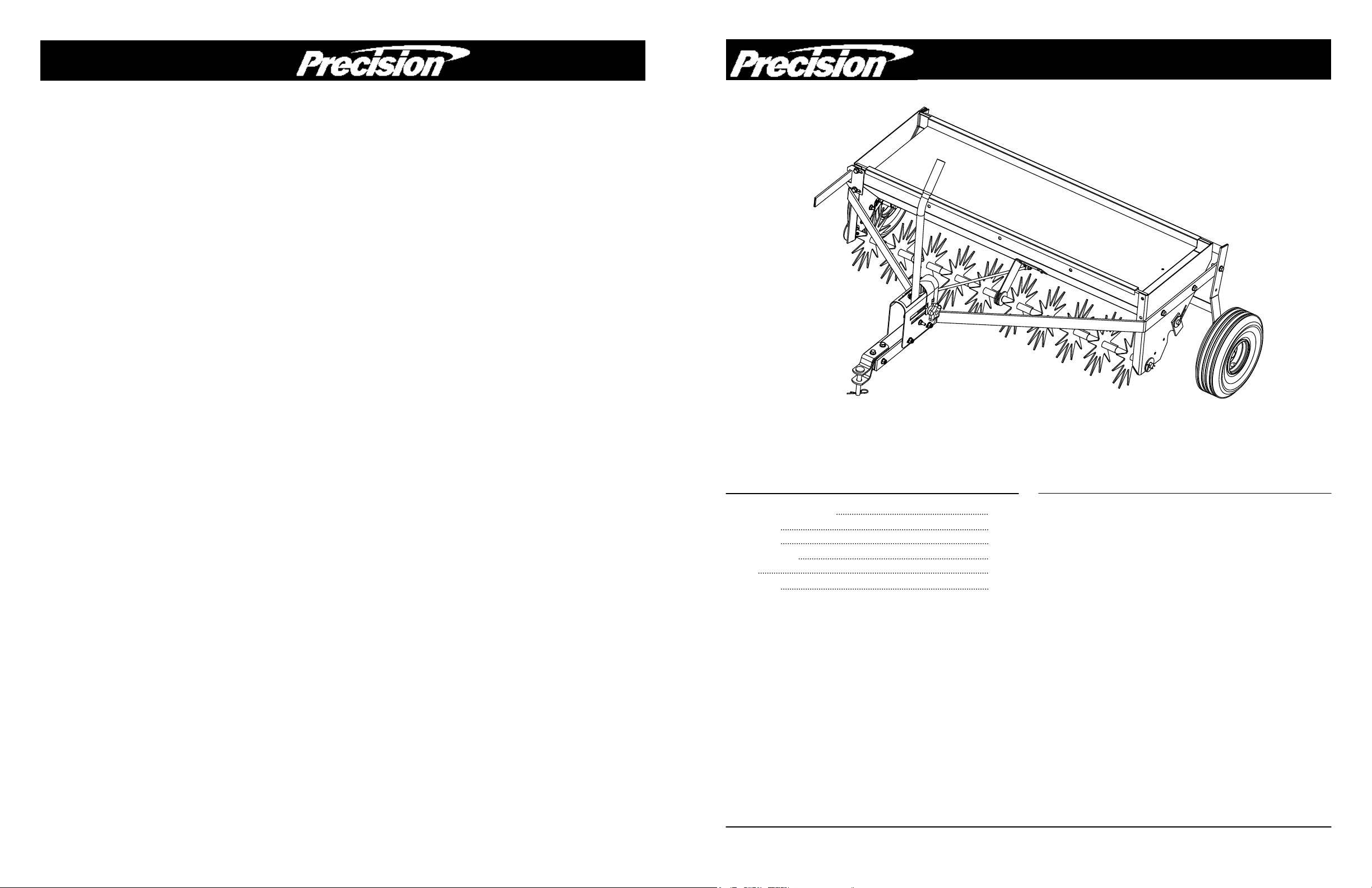
Manufacture’s Limited Warranty for Pull Behind Accessories
42” Spike Aerator /
Owner’s Manual | TDSA42PT | Drop Spreader Combo
Caution: Read all Safety Instructions and Operating Instructions Carefully.
Manual Contents
Your New Spike Aerator
Congratulations on your purchase of a new
Precision Products Inc. Spike Aerator/Drop Spreader
Combo. Your aerator/drop spreader combo has
been engineered and built to give you the most
dependable and best performing product possible.
If you experience any problem you can not easily
resolve, please feel free to contact our
knowledgeable and helpful customer service
department toll-free at 1 (800) 225-5891.
Form No. 4243-3 (Rev. 07/09)
Safety Instructions
Assembly
Operation
Maintenance
Parts
Warranty
2
4-5
5
5
6-7
8
Tread pattern on tires may vary.
Page 2
2
Safety Instructions
All power equipment can cause injury or property damage if operated improperly. Please read and observe
the following safety rules and exercise caution at all times when operating equipment.
Read and understand your tractor’s owner manual and towing safely rules. Know how to operate your tractor before using any
attachment.
Never allow children to operate the towing vehicle. Do not allow adults to operate the vehicle without having read the owner’s
manual or receiving proper instruction.
Do not allow anyone to ride or sit on tow behind equipment during operation.
Keep adults, children and animals at a safe distance.
Always wear substantial footwear. Do not wear loose fitting clothing that may get caught in moving parts.
This unit may have sharp points. Handle with care.
Keep your eyes and mind on your tractor/attachment and area being covered. Do not let yourself be distracted.
Stay alert for holes in the terrain and other hidden hazards.
Tractor braking and stability may be affected with the attachment of this unit. Be aware of changing conditions on slopes. Refer
to safety rules in your tractor owner’s manual concerning safe operation on slopes. Stay Off Steep Slopes.
Always operate up and down a slope, never across the face of a slope.
Do not operate close to creeks, ditches or public highways.
Always begin with the transmission in first (low) gear and engine at low speed, and gradually increase speed as conditions
permit.
Keep the tractor and attachment in good operating condition and keep safety devices in place.
Keep all nuts, bolts and screws tight to be sure the equipment is in safe working condition.
The vehicle and attachment should be stopped and inspected for damage after striking a foreign object. Any damage should be
repaired before restarting and operating the equipment.
Follow the maintenance instructions as outlined in this owner’s manual.
Should not be towed at more than 3-4 miles per hours.
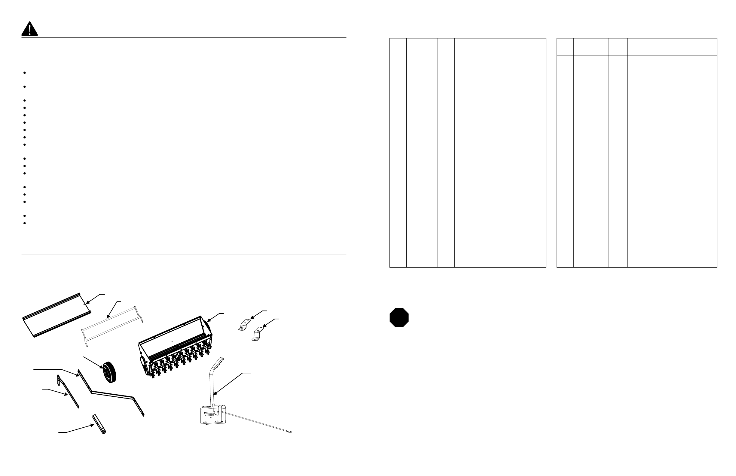
Carton Contents
1. Weight Tray 4. Clevis Plate #2 7. Tow Bar Side (2) 10. Control Housing
2. Wheel Bracket Assembly 5. Clevis Plate #1 8. Wheel
3. Hopper Assembly 6. Wheel Engagement Bar 9. Tow Bar Tube
1
2
3
4
5
6
7
8
9
10
11
Not all parts shown. This a parts list for all parts used in this unit. Parts used by customer for
assembly can be found on page 3.
Parts and Support
Please do not return this product to the
store prior to contacting Precision.
At Precision Products Inc. our goal is to deliver quality, value and outstanding service. If for any reason our
product does not meet your expectations, please contact us and we will take care of any problem you may
have with this unit.
When ordering replacement parts please have the model number, part description, part number, inspector
number and date on box, available so that we can best serve you.
1 (800) 225-5891
www.precisionprodinc.com
Precision Products Inc.
316 Limit St.
Lincoln IL 62656
STOP
Ref
No.
Qty. Description Part No.
1
2
3
4
5
6
7
8
9
10
11
12
13
14
15
16
17
18
19
20
21
22
23
24
25
26
27
28
29
30
31
2
1
1
1
2
1
10
2
21
6
2
2
2
7
7
3
1
10
5
2
1
3
8
4
8
8
8
2
2
1
1
Wheel
Clevis Plate
Clevis Plate
Wheel Bracket Assembly
Tow Bar Side
Tow Bar Tube
Blade (star) Assembly
1/4” x 1’ Hex Head Bolt
1/4” Flat Washer
1/4” Lock Washer
1/2” Nylock Nut
1/2” Jam Nut
1/2” x 3-1/2” Hex Head Bolt
1/2” Flat Washer
1/4” Nylock Nut
5/16” x 2-1/2” Hex Head Bolt
5/16” x 3/4” Carriage Bolt
5/16” Flat Washer
5/16” x 1” Hex Head Bolt
1/2” Lock Washer
3/8” Flat Washer
7/8” E—Clip
5/8” Flat Washer
#6-32 x 1/2” SHCS
#6-32 x 3/4” SHCS
#6-32 MSH Nut
#6 Lock Washer
#10-24 x 1” SHCS
#10-24 MSH Nut
1/4” x 1-1/2” Hex Head Bolt
Chain
3339A
4265GY
4266GY
4152
4164
4165
4156
1061
1817
1807
2311
4324
4224
1506
1558
1441
1314
1044
3738
3414
1278
3980
1646
3982
3983
3984
3985
3986
3987
1647
4170
Ref
No.
Qty. Description Part No.
32
33
34
35
36
37
38
39
40
41
42
43
44
45
46
47
48
49
50
51
52
53
54
55
56
57
58
59
60
61
62
1
1
1
1
1
3
2
1
1
1
2
1
1
1
1
1
1
1
1
1
1
1
16
2
2
14
1
1
1
1
2
Chain Cover
Hopper Assembly
Agitator Bar Assembly
Axle Gear Assembly
Slide Plate Assembly
5/8” Metal Bushing
Agitator Blade
Lock Plate
Center Brace
Control Rod
1/2” Metal Bushing
Wheel Engagement Bar
Engagement Bar Grip
Control Housing
Control Handle
Calibrator Strip
Control Strip
Control Knob
Compression Spring
5/16” x 5/16” Rubber Roller
7/8” Handle Grip
1/4” - 20 x 3” Hex Head Bolt
5/16” Fender Washer
5/16” - 18 x 1-1/4” Hex Head Bolt
5/16” - 18 x 2-3/4” Hex Head Bolt
5/16” - 18 Nylock Nut
Spring
Clevis Pin 5/8” x 2”
Hitch Pin Clip #14
Weight Tray.
3/32” x 1-1/4” Cotter Pin
4150
4151
4153
4154
4155
4158
4159
4160
4161
4162
4163
4157
4168
3977
3976
2163
3967
2158
2157
2178
1029
2179
2172
4281
1707
1749
3979
4289
1042
3974
3191
TDSA42PT
Page 3

10
32
31
35
45
9
8
17
15
9
30
9
46
52
49
53
57
18
9
9
15
16
3
41
56
9
51
5
57
57
60
50
57
59
5
2
16
6
34
3
Parts Used in Hardware Sack
Shown Full Size
Ref. Qty. Description
11
12
13
14
15
16
17
18
19
20
21
22
23
24
25
26
27
6
1
2
3
2
2
3
14
6
1
14
2
1
2
2
1
2
5/16” x 1” Hex Head Bolt
1/4” x 1” Hex Head Bolt
5/16” x 1-1/4” Hex Head Bolt
5/16” x 2-1/2” Hex Head Bolt
5/16” x 2-3/4” Hex Head Bolt
1/2” x 3-1/2” Hex Head Bolt
1/4” Flat Washer
5/16” Flat Washer
1/2” Flat Washer
1/4” Nylock Nut
5/16” Nylock Nut
1/2” Nylock Nut
1/2” x 2” Clevis Pin
5/16” Fender Washer
1/2” Jam Nut
#14 Hitch Pin Clip
1/2” Lock Washer
Having Problems?
Installation Questions?
Missing Parts?
Replacement Parts?
Don’t go back to the store!
Let us help you!
Please call our helpful Customer Service Department
Toll-Free at (800) 225-5891 We will be happy to
assist you.
STOP
11
12
13
14
15
16
17 18
19
23
24
26
20
21
22
25
27
Page 4

4
Assembly Instructions
Tools Required for Assembly
Minimum
(1) 1/2” Wrench
(1) 3/4” Wrench
(1) Adjustable Wrench
Remove from Carton
Remove all parts and hardware packages from the carton. Lay out all parts and hardware and
identify them using the illustrations on pages 2 and 3.
1. Both side bars are the same, attach one to each side of the hopper. You will need four of the
5/16” x 1” Hex Head Bolts, four 5/16” Flat Washers and four 5/16” Nylock Nuts. Push the bolt
through the bars as shown in figure 1. There are two holes in each end of the hopper, line up bolts
with the hole in the hopper. Attach a 5/16” Flat Washer and a 5/16” Nut, onto each bolt.
See Figure 1.
Figure 1
5/16” x 1” Hex Head
Bolt
5/16” Flat Washer
Hopper
Assembly
5/16” Nylock Nut
Tow Bar Side
9
61
4
1
14
57
18
11
37
38
40
18
13
7
22
23
14
12
55
18
54
19
33
57
20
42
43
62
19
Page 5

8
Operation
Raising/Lowering your Spike Aerator/Drop
Spreader Combo
1. Attach the unit to your tractor on a level surface
using the provided hitch pin and hitch pin clip.
2. Once you enter the grassy surface, to lower the
aerator for operation, move the handle to the side
and push back to engage the spikes.
3. When complete, pull handle forward and lock to
raise the unit and engage the wheels.
Using the Spreader/Spike Aerator
Aerating involves cutting small holes into the soil to
create small reservoirs allowing air, fertilizer, and
water to reach the grass or plant’s roots. The
following lawn preparation and aerator operation is
recommended for optimal performance.
Mow the lawn and remove grass clippings prior to
using the spike aerator. Your spike aerator should
be attached to your rider or tractor on a level
surface such as a driveway or garage floor with
wheels engaged.
Once you are on the grass, have the tractor in the
lowest forward speed and then disengage the
wheels by moving the handle out of the locked
position. This will allow the spikes to enter the
ground. Speed can be increased as conditions
permit. On slopes, always operate in an up and
down direction only. Overlapping passes can be
done to increase the density of the spike point
pattern.
DO NOT make sharp turns while the spike points
are engaged in the ground as this will damage the
lawn. Weight can be placed on the top plate to
increase the depth of spike point penetration.
Weight may be needed for many applications, but
DO NOT exceed the maximum weight of 175 lbs.
The plate has been designed to hold concrete
blocks. Secure the blocks with suitable binding
material such as rubber tie down straps or wire. Not
for use with Zero Turn Radius Mowers.
Maintenance
1. Before each use, check all nuts and bolts for
tightness.
2. Clean after each use to prevent rust. The key to
years of trouble-free service is to keep your unit
clean and dry.
3. If rust should develop, sand lightly and then paint
area with enamel.
4. Periodically check all moving parts for free
movement and if necessary, lubricate with oil.
5. Sharpening spike points will allow you to
maintain good soil penetration.
Storage
1. Be careful to store your spike aerator with the
spikes towards the floor or a wall. Spikes are sharp
and can cause considerable damage.
2. Always store your spike aerator in a dry area,
and coat exposed metal with light oil when not in
use.
43
19
5
2. Attach the Tow Bar Tube by placing the tube between the side bars. Insert a 5/16” x 2-1/2” Hex Head Bolt
and push the bolt through the end hole of the Tow Bar Side and Tow Bar Tube. Place a 5/16” Nylock Nut
onto each bolt. Attach the Control Housing by lining up the other two holes in the out outside of the Tow Bar
Sides. Using two 5/16” x 2-3/4” Hex Head Bolts, and two 5/16’ Nylock Nuts. Line up the holes in the
housing, then secure with a Nylock Nut. (Do not tighten the Nylock Nuts until after you adjust the Control
Housing. The Control Housing should come fully assembled with the Control Rod and Handle mounted to the
housing as shown in Figure 2.
3. Do not adjust the Control Housing until after you have attached the Control Rod.
4. You will need to turn the unit over to attach the Control Rod to the Slide Plate Assembly. Take a 1/4” x 1”
Hex Head Bolt, three 1/4” Flat Washers and a 1/4” Nylock Nut. Attach a 1/4” Flat Washer to the bolt. Line up
the hole to the Control Rod insert bolt and add another 1/4” Flat Washer, insert the bolt through the Slide
Plate, add one more 1/4” Flat Washer and secure with a 1/4” Nylock Nut. See Figure 3.
Figure 2
5/16” x 2-1/2” Hex Head Bolt
5/16” x 2-3/4” Hex
Head Bolt
Control Housing
Tow Bar
Tube
5/16” Nylock
Nut
Page 6

6
Figure 4
5. Turn the unit back over, once this is completed. Place the Handle in the fully closed notch, look and see if the holes
into the hopper are covered. Then place the Handle in the fully open notch, make sure the holes are uncovered to adjust, slide the Control Housing forward or backwards and then tighten the 5/16’ Nylock nut.
6. Place the Wheel Bracket over the outside of the Tow Bar Sides. Line up the top holes with the holes in the end of
Tow Bar Sides and the top hole in the Engagement Bar as shown in Figure 4. Use a 5/16” x 1-1/4” Hex Head Bolt with a
5/16” Flat Washer, push bolt through the Wheel Engagement Bar and the Wheel Bracket, add a 5/16” Fender Washer
and then push through the Tow Bar Side, add one more 5/16” Flat Washer and then secure with a 5/16” Nylock Nut.
Use a 5/16” x 1” Hex Head Bolt with a 5/16” Flat Washer to go through the bottom hole of the Engagement Bar and
Wheel Bracket. Add a 5/16” Flat Washer and secure with a 5/16” Nylock Nut on the inside. On the right side use a 5/16”
x 1” Hex Head Bolt with a 5/16” Flat Washer, push through Wheel Bracket and add a 5/16” Fender Washer, then push
bolt through Tow Bar Side. Add a 5/16” Flat Washer and secure with a 5/16” Nylock Nut. See Figure 4.
Figure 3
1/4” Flat Washer
1/4” x 1”
Hex Head
Bolt
Connecting Rod
1/4” Flat Washer
1/4” Nylock
Nut
Slide Plate
Assembly
5/16” Flat
Washer
5/16” Nylock
Nut
5/16 Flat Washer
5/16” x 1-1/4”
Hex Head Bolt
5/16” Fender
Washer
5/16” x 1”
Hex Head
Bolt
5/16” x 11/4” Hex
Head Bolt
5/16” Flat
Washer
5/16” Fender Washer
7
Figure 5
7. Attach Wheels to the Wheel Bracket, using two 1/2” x 3-1/2” Hex Head Bolts, six 1/2” Flat Washers, two 1/2” Nylock
Nuts and two 1/2” Jam Nuts. Place a 1/2” Flat Washer on a 3-1/2” Hex Head Bolt, then place the Wheel on the bolt, add
two more 1/2” Flat Washer, then screw on the Nylock Nut. Place the bolt through the hole in the Wheel Bracket and
then secure with a 1/2” Lock Washer and a 1/2” Jam Nut. See Figure 5.
8. To attach the Clevis Plates to the Tow Bar Attachment, you will need two 5/16” X 2-1/2” Hex Head Bolts, four and
two 5/16” Nylock Nuts. Place the Clevis Plates as shown in Figure 6. Push the bolts through the holes in the Clevis Plate
and Tow Bar add a 5/16” Nylock Nut to each bolt. Insert the 1/2” x 2” Clevis Pin into the first hole and secure with a
#14 Hitch Pin Clip.
1/2” x 3-1/2”
Hex Head Bolt
1/2” Lock
Washer
1/2” Nylock
Nut
1/2” Jam
Nut
Figure 6
1/2” x 2”
Clevis
Pin
Clevis
Plate
5/16” Nylock
Nut
#14 Hitch
Pin Clip
5/16” x 2-1/2”
Hex Head Bolt
1/2” Flat
Washer
 Loading...