

Page 1
Operating Instructions
350-8132-000 d1
Precisa 360 ES
EXECUTIVE
Page 2

Page 3
Identification ■
1
English
Identification
Customer service
Precisa Gravimetrics AG
Moosmattstrasse 32
CH-8953 Dietikon
http://www.precisa.com
Refer to our website for information about local customer service centers and details of their addresses.
Copyright
These operating instructions are protected by copyright. All rights reserved. No part of the operating instructions may be reproduced,
processed, duplicated or published in any form by photocopying, microfilming, reprinting or other process, in particular electronic
means, without the written agreement of Precisa Gravimetrics AG.
© Precisa Gravimetrics AG, 8953 Dietikon, Switzerland, 2012
Page 4
■ 1 Overview
2
1Overview
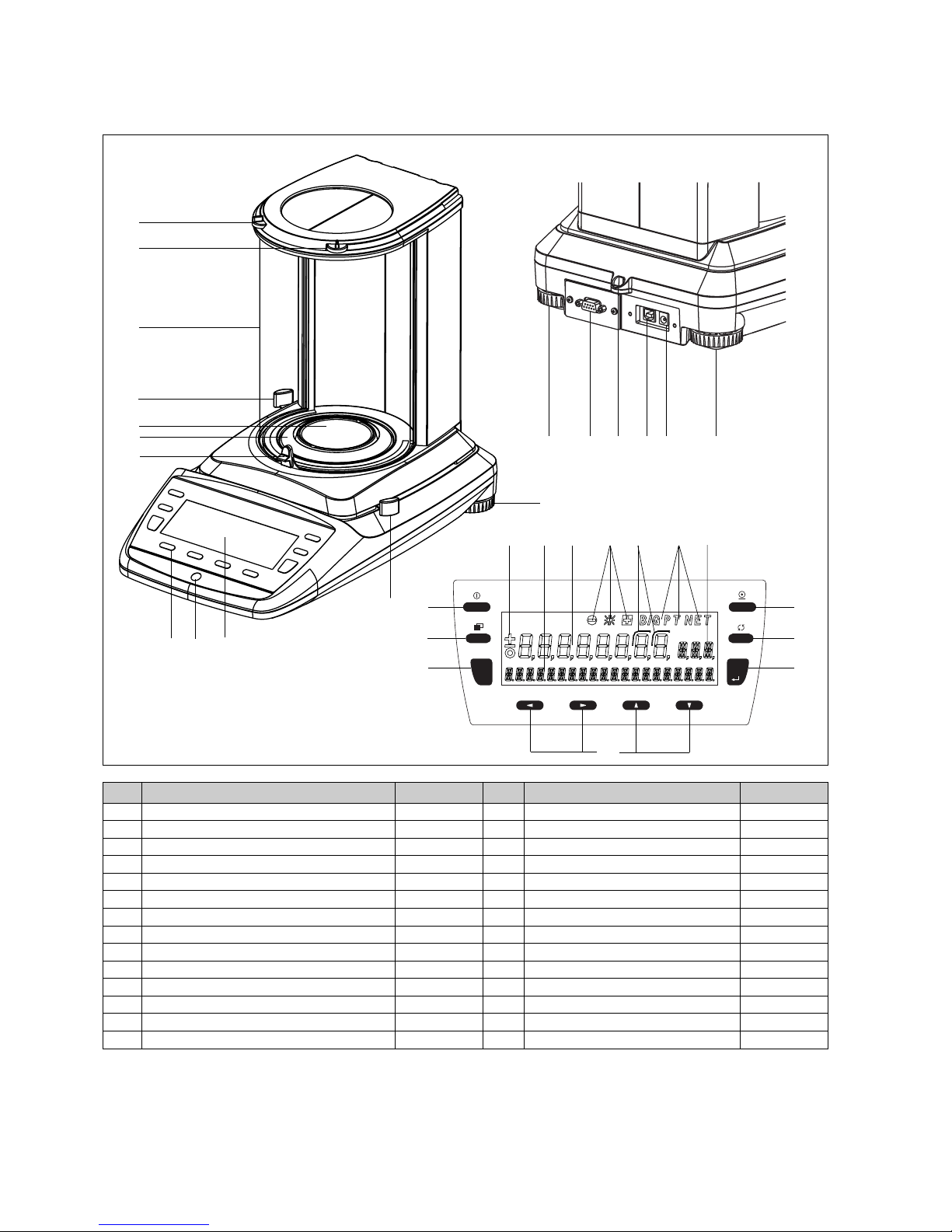
No. Description Section / Page No. Description Section / Page
1 Top draft shield opening 15 Prefix display 9.9 / 14
2 Draft shield 2 / 3 16 Info display
3 Side draft shield opening 17 Measurement display
4 Weighing pan 2 / 3 18 Weight check 13 / 34
5 Protective ring 2 / 3 19 Brackets to mark not approved digits
6 Switch for draft shield opening mode 20 Symbol display
7 10-key control panel 10.1 / 15 21 Unit display 10.3.2 / 17
8 Levelling bubble 9.6 / 13 22 ON / OFF key 9.10 / 14
9 Display 23 Menu / ESC key 10.5.1 / 24
10 Adjustable feet 9.6 / 13 24 Tare / Insert key 10.4.1 / 23
11 Serial interface, DB9 Female 21.1 / 66 25 Cursor keys 10.1 / 15
12 Mechanical anti-theft protection 26 Print key 10.4.2 / 23
13 USB device connector for connection to PC 21.1 / 66 27 Change / Clear key 10.4.3 / 24
14 Connecting socket for power adapter 9.5 / 13 28 Tare / Enter key 10.4.1 / 23
0/T0/T
ins
esc
clr
10
4
1
2
1
7
9
1211 13 14 10
22
23
24
25
26
27
28
5
8
10
15
16
18
19 20
17
3
3
6
21
Page 5
2 Inspection and assembly ■
3
English
2 Inspection and assembly
Inspect delivery for complete supply immediately on unpacking all components.
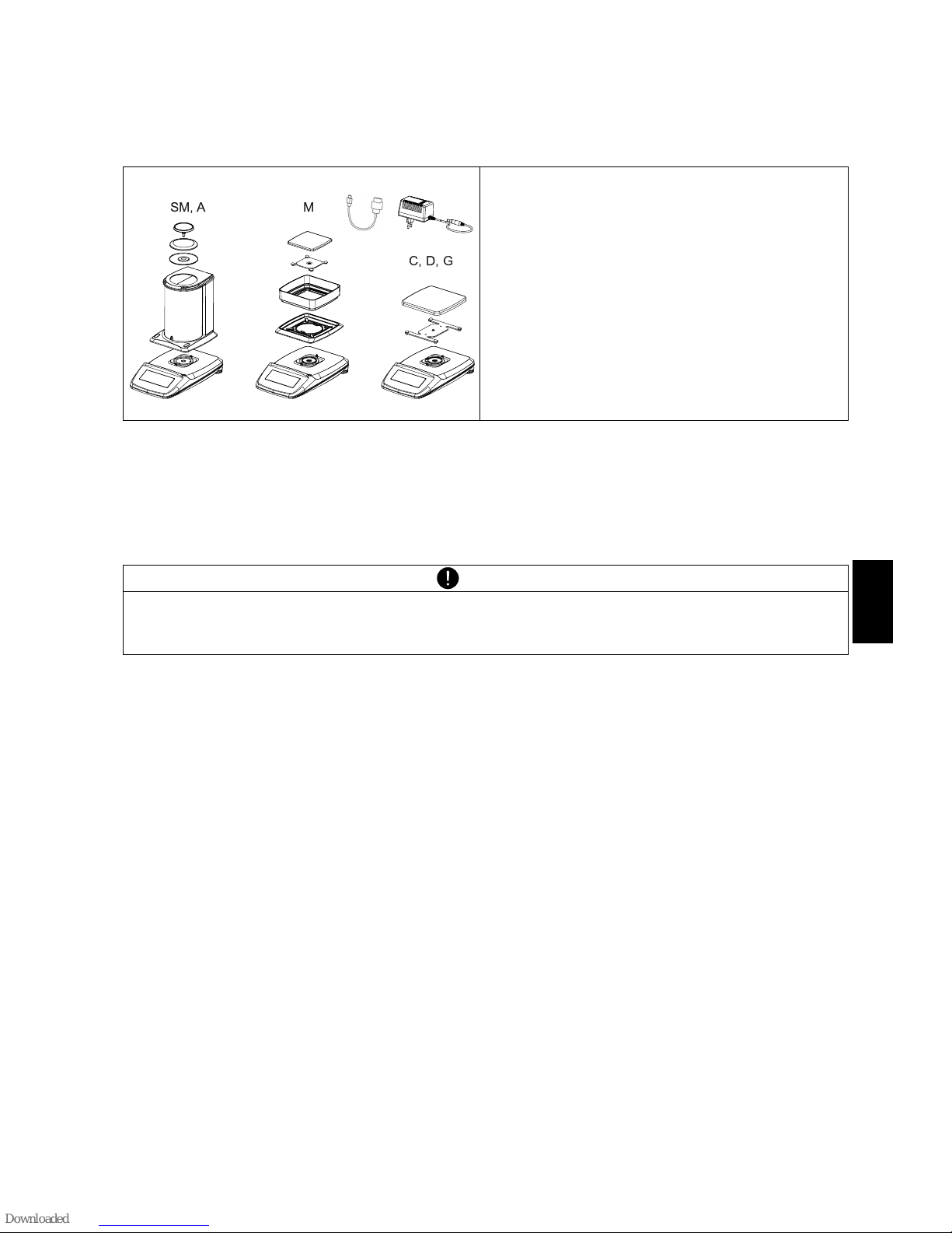
The balance is delivered in partly dismantled condition. Assemble the individual components in the following
sequence:
• Install the draft shield as well or the protective ring with the two screws supplied
• Place the weighing pan in position
• Insert the power adaptor cable plug into the socket at the rear of the balance.
Components supplied, depending on balance type
• Weighing pan
• Pan holder
• Protective ring for SM and A balances
• Protective ring for M balances
• Draft shield for SM and A balances
• Draft shield for M balances
• Balance
• Power adapter and USB cable balance to PC
• Protection-cover for the balance or display
• Short instructions
• Security card
• Conformity note
• CD with operating instructions
NOTE
A screwdriver is required for assembly.
All parts must fit together easily. Do not apply force. Customer Service will be pleased to help you with
any problems.
SM, A M
C, D, G
Page 6

■ 3 Firmware and serial number
4
3 Firmware and serial number
After a reconnection of the balance to the mains and switching on for the first time the serial number as well
as the firmware will be showed in the upper display.
4 Data and parameters
The balances are divided into five main-groups SM, A, C, D, G and M. The letter in the name corresponds
to the design specification (e.g. SM= semi micro, A = analytical balance, M = MilIigramme balance) the
number before it corresponding in each case to the maximum allowable load (in grammes).
The allowable weighing range, the calibration value and the readability of the balance are printed on the type
plate and sales plate sticked to the casing and are therefore not presented here.
The following applies to all balances:
• Mains connection
– 115 - 230V (+15/-20%); 50 - 60Hz
• Power consumption
– without peripheral appliances 18.0 VA
• RS232/V24 Interface
• USB device Interface
• Allowable ambient conditions
– Temperature: 5°C … 40°C
– Relative humidity: 25%... 85%, non-condensing
• If you have any questions on the technical data or require detailed technical information on your balance,
please contact your Technical Representative.
Display Remark
4700051
Serial number: 4700051
01,00 P04 B00
Firmware: B01-0100.P04
B00: Hardwarecode 01,00: Version P04: Release
Page 7
5 Below-balance weighing ■
5
English
5 Below-balance weighing
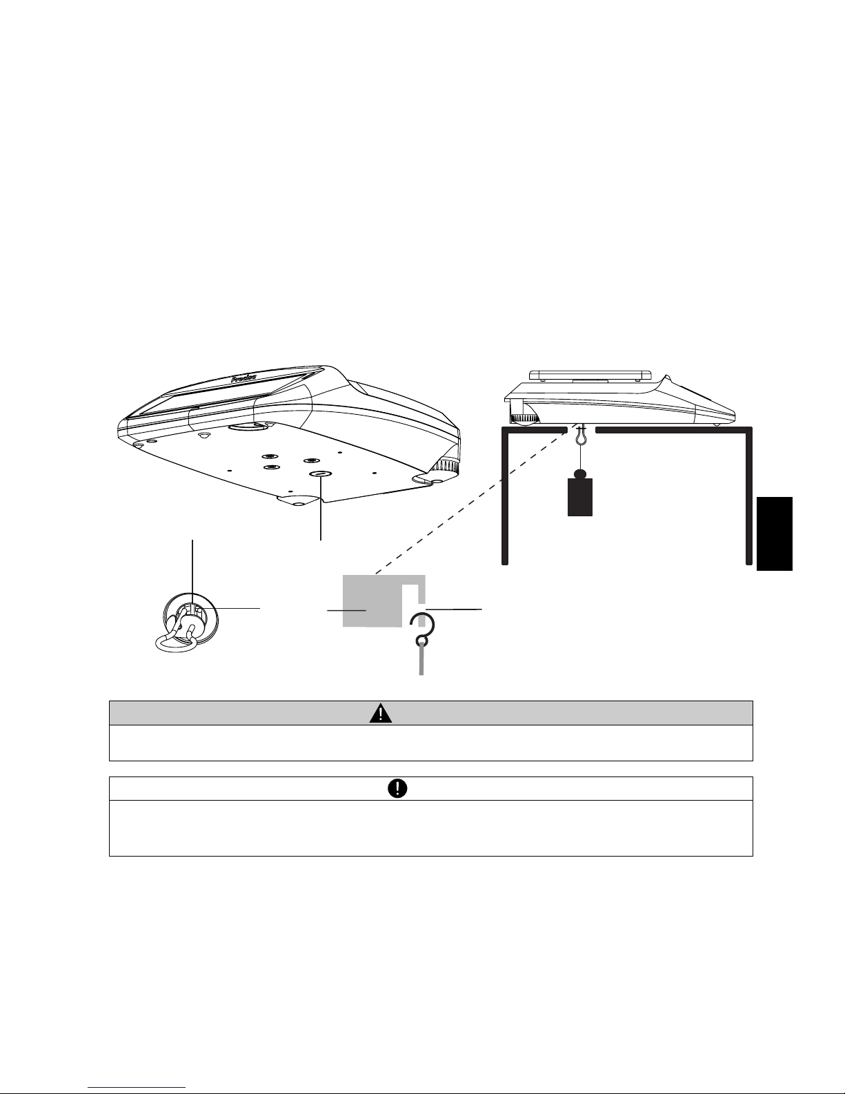
Objects which, because of their size or shape, cannot be put on the scale, can be weighed by means of below-balance weighing.
Proceed as follows:
• Turn off the balance.
• Remove the weighing pan and the pan holder than turn the balance up side down.
• Push the metal-cover (1) on the floor of the balance to one side.
• Hang a small hook (available as an accessory, see chapter 6 "Accessories") into the aperture (3) of the
now visible metal casting (2).
• Place the balance over an opening.
• Replace the pan holder and the weighing pan.
• Level the balance (see chapter 3.6 "Levelling")
• Switch on the balance.
• Hang the object to be weighed on the hook and carry out the weighing.
CAUTION
Take care that the hooks used for the below-balance weighing are stable enough to hold the goods
which you wish to weigh.
NOTE
Take care that no dirt or moisture can get into the balance with the weighing pan removed.
After completing the below-balance weighing, the opening in the floor of the balance must be closed again
(dust protection).
kg
3
2
2
3
1
Page 8

■ 6 Accessories
6
6 Accessories
Additional SmartBox® Applications, Precisa BUS accessories, further special accessories and options on demand.
Accessorie Article number
Draft shield 360 automatic for 0.01mg and 0.1mg balances, height 260mm 350-8657
Draft shield 360 automatic for 0.01mg and 0.1mg balances, height 180mm 350-8658
Draft shield 360 manual for 0.01mg and 0.1mg balances, height 180mm 350-8660
Draft shield 320 XB for 0.01mg and 0.1mg balances, height 260mm
requires adapter for 1mg, 0.01g, 0.1g and 1g balances*
350-8519
Draft shield 320 XB for 0.01mg and 0.1mg balances, height 180mm
requires adapter for 1mg, 0.01g, 0.1g and 1g balances*
350-8518
*adapter for 1mg, 0.01g, 0.1g and 1g balances 350-7402
Draft shield mg, glass with cover 320-8504
Density kit for 0.01mg and 0.1mg balances
Container size Ø 75mm, height 100mm
350-8536
Density kit for solids only (w/o Glass body and Hook) for 0.01mg and 0.1mg balances
Container size Ø 75mm, height 100mm
350-8537
Glass body 10ccm for density determination of liquids 350-7054
Downholder for samples with density < 1 g/cm3 350-7194
Animal weighing bowl complete for 0.01g, 0.1 and 1g balances 350-8551
Diamond weighing pan 350-8322
Hook for weighing below the balance 350-8527
Dust cover 360 for the whole balance, set of 20 pieces (for 0.01mg and 0.1mg balances) 350-8663 (350-8676)
Data cable DB9 Male / DB9 Female (PC), 1.5m 350-8672
Data cable DB9 Male / DB25 Male (Printer), 1.5m 350-8673
Slide-in modules Article number
Precisa BUS converter 350-8664
Page 9
6 Accessories ■
7
English
Page 10

■ Contents
8
1 Overview ................................ 2
2 Inspection and assembly ........... 3
3 Firmware and serial number ...... 4
4 Data and parameters ................ 4
5 Below-balance weighing ........... 5
6 Accessories ............................ 6
7 Introduction .......................... 10
7.1 Useful tips on the Operating Instructions10
7.2 Warranty card ................................. 10
7.3 Conformity ..................................... 10
8 Safety .................................. 11
8.1 Representations and symbols ............ 11
8.2 Safety recommendations .................. 11
9 Set up .................................. 12
9.1 Unpacking the balance ..................... 12
9.2 Transport and shipping..................... 12
9.3 Storage .......................................... 12
9.4 Choosing a suitable location.............. 13
9.5 Connecting the balance to the mains.. 13
9.6 Levelling......................................... 13
9.7 Calibration of the balance ................. 13
9.8 Dual Range and Floating Range balances14
9.9 Standardized balance ....................... 14
9.10 Switching on the balance ................. 14
9.11 Auto-Standby Mode......................... 14
10 Operation.............................. 15
10.1 Menu control operation principle........ 15
10.1.1 Operating in the Weighing mode ....... 15
10.1.2 Operation in the programming mode .. 16
10.2 Setting the factory configuration ....... 16
10.3 Device configuration ........................ 16
10.3.1 Activating the configuration menu ..... 17
10.3.2 Selecting the weight unit.................. 17
10.3.3 Print functions................................. 18
10.3.4 Calibration functions ........................ 18
10.3.5 Weighing mode ............................... 19
10.3.6 Interface functions........................... 20
10.3.7 Date and time. ................................ 20
10.3.8 Anti-theft encoding.......................... 21
10.3.9 Key tone ........................................ 22
10.3.10 Precisa BUS.................................... 22
10.3.11 Language function........................... 22
10.3.12 Backlight ........................................ 22
10.3.13 Automatic draft shield...................... 22
10.4 Special operating keys...................... 23
10.4.1 The tare key ................................... 23
10.4.2 The print key .................................. 23
10.4.3 The change key............................... 24
10.5 Application menu............................. 24
10.5.1 Activating the application menu ........ 24
10.5.2 Selecting an application program ....... 25
11 Application ............................ 26
11.1 Units.............................................. 26
11.2 Count ............................................ 26
11.3 Percent .......................................... 27
11.4 Calculator....................................... 28
11.5 Paper ............................................. 29
11.6 Net-Total........................................ 29
11.7 Sum............................................... 30
11.8 Animal ........................................... 31
12 Statistics ............................... 32
13 Check-Weighing ..................... 34
14 Density ("DENSITY") .............. 36
14.1 Explanatory notes on density determination
36
14.1.1 Methods of determination................. 36
14.1.2 Density index calculation.................. 36
14.2 Selecting the density determination
application...................................... 36
14.3 Configuring the density determination 37
14.4 Starting and initializing the density program
37
14.5 Density of a liquid "MODE LIQUID"
(with density kit 350-8515) .............. 38
14.6 Density of a solid "MODE SOLID IN AIR"
39
14.7 Density of a porous solid
"MODE SOLID POROUS".................. 40
14.8 Density of a solid
"MODE SOLID ON THE BOTTOM"..... 41
15 Differential weighing
("DIFF.-WEIGHT")................... 42
15.1 Explanatory notes on differential weighing
42
15.2 Selecting the differential weighing
application...................................... 42
15.3 Configuring the differential weighing.. 42
15.3.1 Overview........................................ 42
15.3.2 Units.............................................. 43
15.4 Working with differential weighing..... 44
15.4.1 Mode, measurement recording .......... 45
15.4.2 Measurement.................................. 46
15.4.3 Sample information.......................... 47
15.4.4 Deleting samples, groups.................. 48
15.4.5 Statistics........................................ 48
Page 11
Contents ■
9
English
15.4.6 Report ............................................48
15.4.7 Remote control commands ................49
16 Minimum original weight
("MIN.-WEIGHT") ................... 50
16.1 Explanatory notes on the minimum
sample weight application, MSW........50
16.1.1 Minimum original weight and quality
management....................................50
16.2 Selecting the minimum original
weight application ............................50
16.3 Configuring the minimum original weight51
16.3.1 Variable menu settings......................51
16.3.2 Non-variable menu settings................51
16.4 Working with the minimum original weight
52
16.4.1 Indicator for "value below minimum original
weight"...........................................52
16.4.2 Displaying additional information with
the function key «MIN...»..................53
16.4.3 Resetting with the function key «>0<»53
16.5 Determining the minimum original
weight periodically ...........................53
17 Dynamic weighing
("DYN.-WEIGHT") .................. 56
17.1 Introduction to the dynamic weighing
application.......................................56
17.2 Selecting the dynamic weighing application
56
17.3 Configuring dynamic weighing ...........56
17.4 Dynamic weighing............................56
18 Pipette calibration ("PIPETTE"). 57
18.1 Introduction to pipette calibration .......57
18.2 Selecting the pipette calibration application
57
18.3 Configuring the pipette calibration ......57
18.4 Working with the pipette...................58
18.4.1 Conducting the pipette test ...............59
18.4.2 Report ............................................61
19 Air buoyancy correction ("BEST").
62
19.1 Introduction to air buoyancy correction62
19.2 Selecting the air buoyancy correction
application.......................................62
19.3 Configuring the air buoyancy correction62
19.4 Working with the air buoyancy correction
62
19.4.1 Weighing weights.............................63
19.4.2 Changing the air density....................63
19.4.3 Changing the material density............63
20 User profiles
(MUM, Multiuser Memory) ...... 64
20.1 Activating a user..............................64
20.2 Creating a new user profile................64
20.3 Changing the password and
password protection.........................65
20.4 Clearing a user.................................65
20.5 Setting the user ...............................65
21 Data transfer ......................... 66
21.1 Connection scheme ..........................66
21.2 Remote control-commands ................67
21.2.1 Examples for the remote control.........68
22 Maintenance and servicing ...... 69
22.1 Calibration.......................................69
22.1.1 External calibration by means of ICM ..69
22.1.2 External calibration with freely
selectable weight .............................69
22.1.3 Internal calibration............................70
22.1.4 Automatic calibration........................70
22.2 Automatic Repeatability Test (ART) ....70
22.3 Software update ..............................71
22.4 Cleaning..........................................71
22.5 Error messages ................................72
22.5.1 Notes on correcting faults .................72
23 Menu trees............................ 73
23.1 Configuration menu tree ...................73
23.2 Application menu tree.......................75
Page 12
■ 7 Introduction
10
7 Introduction
These balances are simple and functional to operate.
The versatile weighing programs allow you to use these balances not only for simple weighing procedures
but also in a simple manner for carrying out various weighing applications such as, for example, percentageor component counting weighings and document the measurements obtained accurately and unequivocally.
Virtually all models can be delivered in weights and measures approved.
The most important basic production features of the Precisa balances include:
• Simple-to-use 10-key multifunction control panel
• Large LCD display with multi-line display
• Anti-theft encoding with four-figure numerical code
• 10 user profiles (MUM Multiuser Memory)
• ICM-Autocalibration (intelligent calibration mode)
• USB device interface for data transfer to PC
• RS232/V24 serial interface for data transfer to PC or printers
• ISO- and GLP-compliant reporting of results of measurements
• Capacity and residual tare display
• Various application programs:
Piece counting, Percentage weighing, Formulation, Animal weighing, Calculator, Check and reference
weighing and lot others
• Statistics program
• Appliance for below-balance weighing
7.1 Useful tips on the Operating Instructions
You should read through these operating instructions in their entirety, so that you can make optimum use of
the full potential and the diverse features of the balance in your daily work.
These operating instructions contain guidance in the form of pictograms and keyboard diagrams, which
should help you find the required information:
• Key names are presented in quotation marks and are highlighted in semi-bold script:
«ON/OFF» or «
F».
• When explaining the operating steps, the appropriate display for the current operating step is shown for
clarity at the left alongside the list of operating steps:
7.2 Warranty card
A warranty card, which was filled in by your dealer before handing over the balance, is enclosed with the
instruction manual.
7.3 Conformity
The balance has been manufactured and tested in accordance with the standards and recommendations set
out in the enclosed certificate of conformity.
The power adaptor produced for the operation of the balance and intended exclusively for this application,
complies with Electrical Protection Class II.
Display Key Step
- - - - - - - -
«D»
Press repeatedly, until the language currently activated is displayed.
language english
NOTE
Check that the warranty card is enclosed with these operating instructions and is completely filled out.
Page 13
8 Safety ■
11
English
8Safety
8.1 Representations and symbols
Important safety instructions are highlighted with the appropriate symbol:
8.2 Safety recommendations
• When using the balance in surroundings with increased safety requirements the corresponding regulations
must be observed.
• The balance may only be used with the power adaptor supplied exclusively for use with this balance.
• Before plugging in the power adaptor, make sure that the operating voltage stated on the power adaptor
agrees with the mains voltage. If not, please refer to the Customer Service.
• If the power adaptor or its cable is damaged, the balance must immediately be disconnected from the electricity supply (pull out the power adaptor). The balance may only be operated with a power adaptor in perfect condition.
• If there is any reason to believe that it is no longer possible to operate the balance without danger, the balance must immediately be unplugged from the electricity supply (pull out power adaptor) and secured
against inadvertent operation.
• In carrying out maintenance work, it is essential to heed the recommendations in chapter 22.4 "Cleaning".
• The balance must not be operated in an area subject to explosion risks.
• Take care when weighing liquids that no liquid is spilt into the inside of the balance or into connections on
the rear of the equipment or the power adaptor.
If liquid is spilt on the balance, the latter must immediately be unplugged from the mains electricity supply
(pull out power adaptor).
The balance may only be operated after it has first been re-checked by a Service technician.
• The operating instructions must be read by each operator of the balance and must be available at the workplace at all times.The balance may only be used for the weighing of solid-materials and of liquids filled into
secure containers and for animal weighing and density determinations. The maximum allowable load of the
balance must never be exceeded, otherwise the balance may be damaged.
• When using the balance in combination with other appliances, the current regulations for the safe use of
the relevant attachments and their application in accordance with instructions must always be observed.
DANGER
Warning of a possible danger which can lead to death or to serious injuries.
CAUTION
Warning of a possibly dangerous situation which can lead to less severe injuries or damage.
NOTE
Tips and important rules on the correct operation of the balance.
Page 14
■ 9 Set up
12
9Set up
9.1 Unpacking the balance
The balances are delivered in an environmentally-friendly package, specifically developed for this precision
instrument, which provides optimum protection for the balance during transportation.
In order to avoid damage, attention must be given to the following points when unpacking the balance:
• Unpack the balance carefully. It is a precision instrument.
• When outside temperatures are very low, the balance should first be stored for some hours in the unopened transport package in a dry room at normal temperature, so that no condensation settles on the balance when unpacking.
• Check the balance immediately after unpacking for externally visible damage. If you should find transport
damage, please inform your Services representative immediately.
• If the balance is not to be used immediately after purchase but only at a later time, it should be stored in
a dry place where fluctuations in temperature are as low as possible (see chapter 9.3 "Storage").
• Read through these operating instructions, even if you already have experience with balances, before you
work with the balance and pay attention to the safety recommendations (see chapter 8 "Safety").
9.2 Transport and shipping
Your balance is a precision instrument. Treat it with care.
Avoid shaking, severe impacts and vibration during the transportation.
Take care that there are no signification temperature fluctuations during the transportation and that the bal-
ance does not become damp (condensation).
9.3 Storage
If you would like to take the balance out of service for an extended period, disconnect it from the electricity
supply, clean it thoroughly (see chapter 22.4 "Cleaning") and store it in a place which meets the following
conditions:
• No violent shaking, no vibrations
• No significant temperature fluctuations
• No direct solar radiation
•No moisture
NOTE
Retain the original packaging in order to avoid transportation damages when shipping or transporting the
balance and to allow the balance to be stored in the best conditions if it is out of operation for an extended
period.
NOTE
The balance should preferably be dispatched and transported in the original packaging to avoid transportation damage.
NOTE
The balance should preferably be stored in the original packaging, since this provides optimum protection
for the balance.
Page 15
9 Set up ■
13
English
9.4 Choosing a suitable location
The balance location must be chosen in such a way as to guarantee perfect operation of your balance, so
that the allowable ambient conditions and prerequisites are met and maintained:
• Put the balance on a solid, firm and preferably vibration-proof, horizontal base
• Make sure that the balance cannot be shaken or knocked over
• Protect from direct solar radiation
• Avoid drafts and excessive temperature fluctuations
9.5 Connecting the balance to the mains
The following safety recommendations must be observed when connecting the balance to the mains:
9.6 Levelling
To function properly, the balance must be precisely horizontal.
The balance is fitted with one spirit level and two adjustable feet for level-control, with the aid of which it
is possible to compensate for small height differences and/or unevennesses in the surface on which the balance is standing.
The two screw feet must be adjusted so that the air bubble is precisely in the centre of the sight glass of the
bubble level.
9.7 Calibration of the balance
Since the Earth's gravity is not the same everywhere, each balance must – in accordance with the underlying
physical weighing principle – be adjusted to compensate for the gravity at each location. This adjustment
process, known as “calibration”, must be carried out on initial installation and after each subsequent relocation. In order to get exact measurements, it is recommended moreover, that the balance should also be calibrated periodically.
NOTE
With difficult conditions (where the balance may be easily shaken or subject to vibration) the balance can
nevertheless provide accurate results through suitable adjustment of the stability control (see chapter
10.3.5 "Weighing mode").
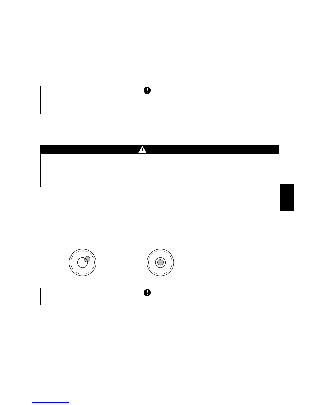
DANGER
The balance may only be operated with the power adaptor supplied.
Check before connecting the power adaptor to the mains supply that the operating voltage stated on the
on the balance or on the power adaptor agrees with the local mains voltage.
If the operating voltage is not the same as the mains voltage, the balance or the power adaptor must on
no account be connected to the mains supply. Contact the Customer Service.
Incorrect Correct
NOTE
In order to get exact measurements, the balance must again be carefully levelled after each relocation.
Page 16
■ 9 Set up
14
Calibration is effected in the configuration menu. Depending on the balance model, this may be done externally, internally or automatically (see chapter 10.3.4 "Calibration functions" and see chapter 22.1 "Calibration").
With the aid of the “Intelligent Calibration Mode” the balance can itself determine the size of the calibration
weight, which enables an exact calibration with different size weights (in 10 g, 50 g, 100 g and 500 g steps,
depending on implementation).
9.8 Dual Range and Floating Range balances
With the Dual Range balances, weighing is always first carried out in the fine range, which is 10 times more
precise. When the fine range is exceeded the balance switches automatically into the coarse range.
The Floating Range balances have a fine range (10 times more precise), which moves over the entire weight
range. By pressing the tare key «T» the fine range can be called up as often as required over the entire weight
range.
9.9 Standardized balance
The standardized balances are provided with the EC/OIML certification or meet the local standardisation regulations.
The balance range and certain functions of the weighing output differ from the standard program in the case
of the standardized balances – in accordance with the EC/OIML provisions.
9.10 Switching on the balance
•Press «ON/OFF» to switch on the balance.
The balance carries out a diagnostic test in order to check the most important functions. After completion
of the start-up process (approximately ten seconds) “Zero” appears in the display.
The balance is ready for operation and is in the Weighing mode.
9.11 Auto-Standby Mode
The balance is equipped with an Auto-Standby mode, which can be activated or deactivated in the configuration menu.
If the Auto-Standby mode is activated, the balance automatically switches to Standby some time after the
last weighing or key operation (current-saving function).
The delay before switching to Standby is defined in the configuration menu (see chapter 10.3.5 "Weighing
mode").
• Press any button or put on a weight in order to switch the balance from the Standby mode back to the
Weighing mode again.
NOTE
The balance must be calibrated on initial installation and after every relocation.
If you work in accordance with “Good Laboratory Practice GLP” observe the prescribed intervals between
calibrations (adjustments).
NOTE
If a circle appears in the main-display of a standardized balance, the indicated value is unstandardised.
In balances of class (1) the circle also stands for the warm-up phase.
Your Customer Service will be happy to assist you at any time if you have any questions on the stand-
ardization of the balance or on working with standardized balances.
Page 17
10 Operation ■
15
English
10 Operation
The balance has two main menus available: the configuration menu and the application menu.
The basic program of the balance is defined in the configuration menu. With this, you can either work with
the basic configuration programmed ex-works, or define and store a user configuration adapted to your specific needs.
In the application menu, you may define an application program which is suited to the specific weighing prob-
lem.
In addition, you may also define the parameters for the statistics program, check-reference weighing and the
user profile in the application menu.
10.1 Menu control operation principle
The configuration menu and the application menu each have several menu levels in which the parameters for
the different function programs of the balance are defined.
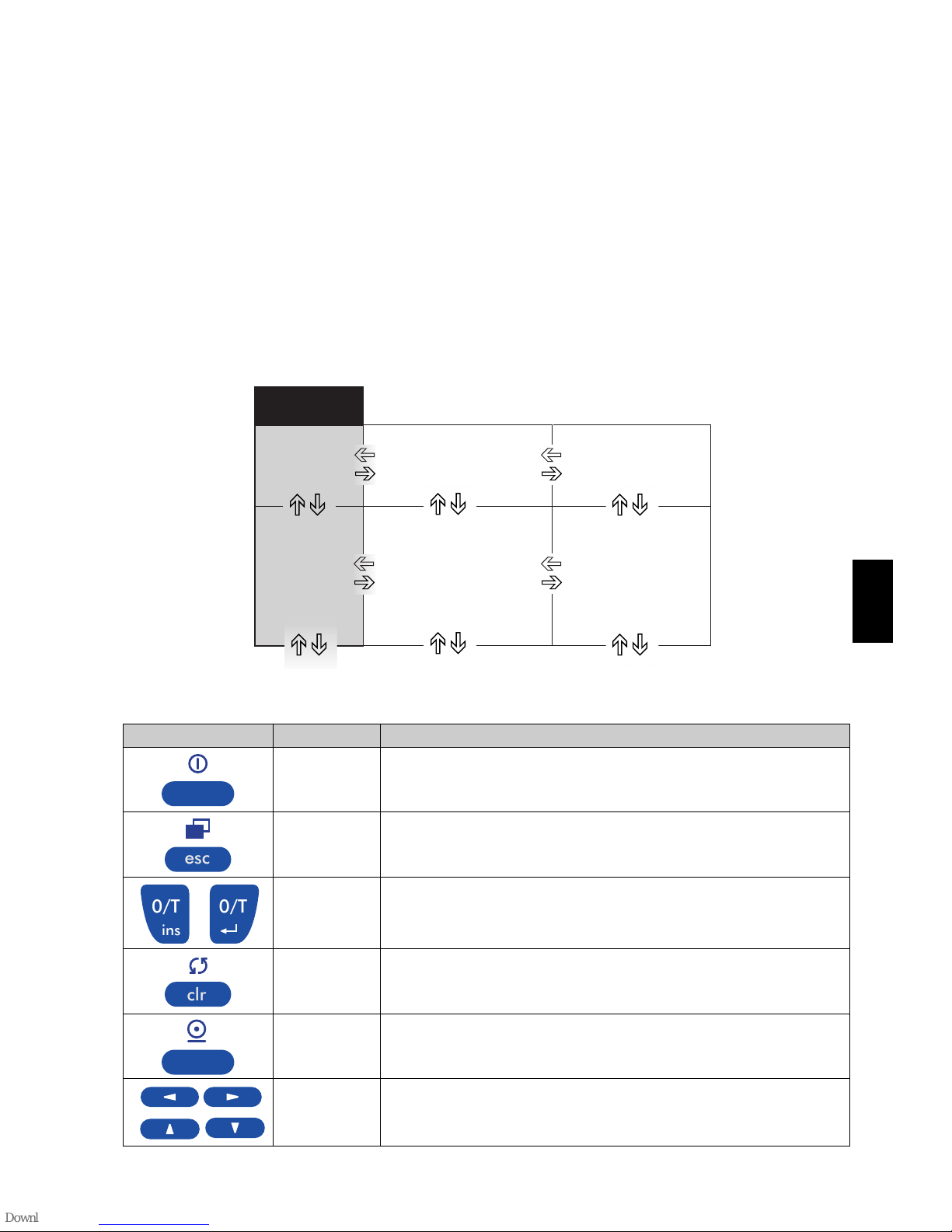
You can move within the menu with the cursor keys «A», «B», «
C» and «D».
10.1.1 Operating in the Weighing mode
Key Designation Function in Weighing mode
«ON/OFF» • Switching the balance on and off
«MENU» • Calling up the Configuration Menu and the Application Menu
«T» • Initiate Tare Function and/or Calibration Function
«
F»
• Switches between the Basic program and the chosen application
«PRINT» • Start print function
«
C»
«A» «B»
«
D»
• Function keys. Start the functions in the info-line.
)
*
)
*
)
*
+
,
+
,
+
,
+
,
+
,
)
*
+
,
esc
0/T0/T
ins
clr
Page 18
■ 10 Operation
16
10.1.2 Operation in the programming mode
The balance can also be operated by remote control. For the corresponding remote control-commands see
chapter 21.2 "Remote control-commands".
10.2 Setting the factory configuration
•Press «ON/OFF» to switch the balance on.
• During the start-up process, hold down the «T» and «MENU» keys until „FACTORY CONFIG.“ appears in
the display, then relase the keys. The balance loads the factory configuration.
10.3 Device configuration
This section explains the structure of the configuration menu and its functions.
The basic adjustment of the balance is defined in the configuration:
NOTE
For the operation of the «T», «F» and «PRINT» see chapter 10.4 "Special operating keys".
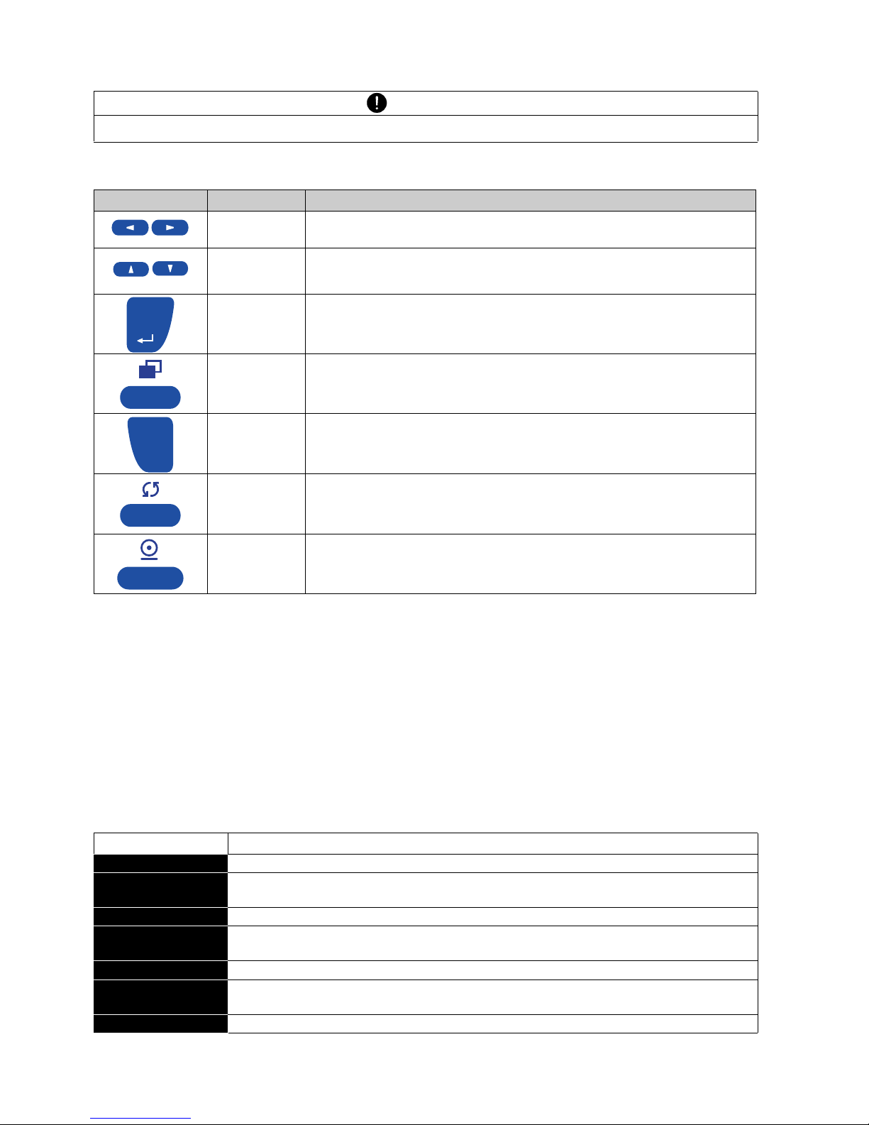
Keys Designation Function in programming mode
«A», «B» • Changes within the menu level
«
C»
«
D»
• Up/Down movements within the menu
• Changes selected parameters
«
E»
• Selects parameters
• Stores the changed parameters
«esc»
• Interrupts an input
• Leaves the menu
«ins» • Places insert marker (in text entry)
«clr» • Deletes input (in text entry)
«PRINT» • Inputs a point (in text entry)
Menu Definable functions
UNIT-1 Unit in which the weighing results are displayed
SET DATA PRINT
Print formats; Type of values to be printed (individual values, continuous printout,
time or load change dependent values, date, time, user, etc.)
SET CALIBRATION Calibration method
SET
WEIGHING MODE
Stability mode (Quality of the balance location), Auto-Standby mode, zero correction, tare method (rapid or standard tare)
SET INTERFACE Baud rate, parity, handshake functions of the peripheral interface
SET
DATE AND TIME
Date and time (standard format or American format p.m. and a.m.)
THEFTCODE Activating/deactivating and changing the anti-theft code.
0/T
esc
0/T
ins
clr
Page 19
10 Operation ■
17
English
• The settings in the sub-paths pre-programmed at the factory are printed here in bold.
• For greater clarity, only that part of the menu tree which corresponds to the function is shown with each
description of the function.
• You will find the entire menu tree for the configuration menu in see chapter 23.1 "Configuration menu
tree".
• Explanations of the menu functions are printed in italics.
10.3.1 Activating the configuration menu
•Press «ON/OFF» to switch the balance on.
• Hold down the «MENU» key continuously during the start-up process (which takes about ten seconds)
until „UNIT-1“ appears in the display.
• You can now change the configuration menu.
10.3.2 Selecting the weight unit
The balance can show results in different units, although with some balances display is not possible in
milligram or kilogram because of the corresponding weight range.
Procedure for changing the weight unit:
KEY TONE Activation of the keypad sound
BUS OFF Enables disables Precisa BUS accessories
LANGUAGE Display language (E, G, F)
BACKLIGHT Display backlight
DRAFT SHIELD Settings of automatic draft shield, if installed
•UNIT-1
UNIT-1 g
kg
----Bht
Gram
Kilogram
----Baht
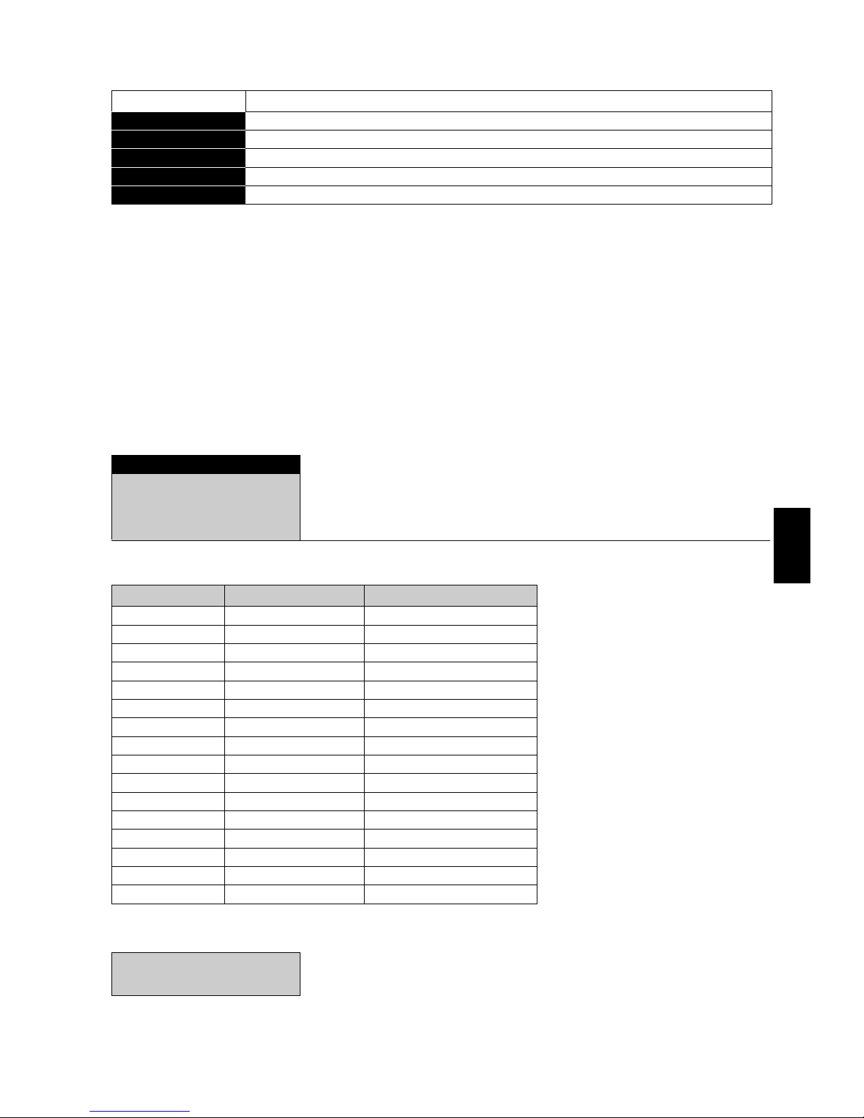
Display Weight unit Conversion to gram
gGram
(mg) Milligram 0,001 g
(kg) Kilogram 1000 g
GN Grain 0,06479891 g
dwt Pennyweight 1,555174 g
ozt Troy ounce 31,10347 g
oz Ounce 28,34952 g
Lb Pound 453,59237 g
ct Carat 0,2 g
C.M. Carat Metric 0,2 g
tLH Tael Hong Kong 37,4290 g
tLM Tael Malaysia 37,799366256 g
tLT Tael Taiwan 37,5 g
mo Momme 3,75 g
t Tola 11.6638038 g
Bht Baht 15.2 g
Display Key Step
- - - - - - - -
«D»
Press repeatedly, until „UNIT-1“ is displayed.
UNIT-1 9
Menu Definable functions
Page 20
■ 10 Operation
18
10.3.3 Print functions
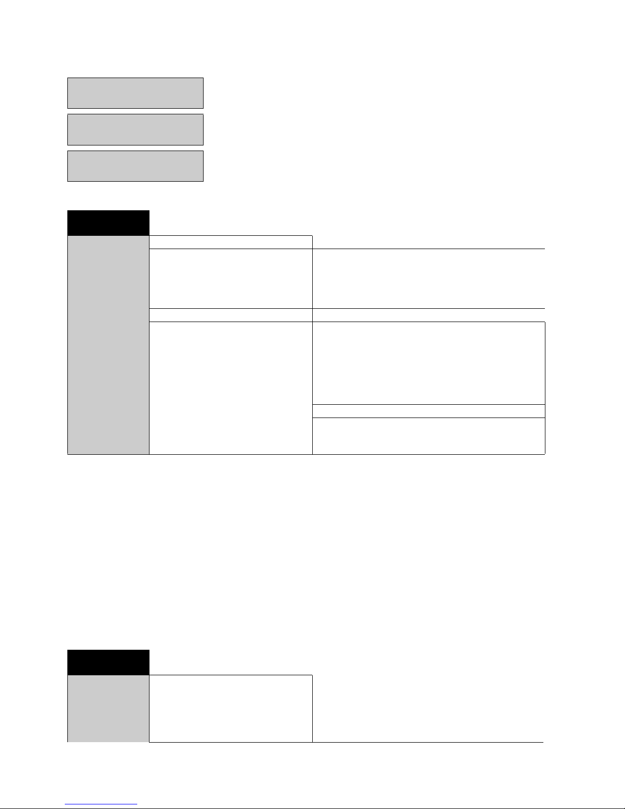
„SET PRINTFORMAT“
Elements which are switched on are printed in each case.
„UNITS”
All currently active units are printed out.
„PRODUCT ttt...”
The product name can be entered alpha-numerically.
„PRODUKTMODE“
– „HOLD“: The product name is stored.
– „DELETE“: The product name is deleted after each expression.
– „COUNT“: A counter, which is incremented by 1 after each expression is printed.
When a peripheral device (for example a printer) is connected, the balance interface must be configured in
the sub-menu „SET INTERFACE” (see chapter 10.3.6 "Interface functions").
10.3.4 Calibration functions
- - - - - - - -
«E»
The unit now flashes
unit-1 9
- - - - - - - -
«D»
Press repeatedly, until the unit you require appears.
unit-1 lb
- - - - - - - -
«E»
To confirm the choice of unit.
unit-1 lb
•SET
DATA PRINT
AUTOSTART ON/OFF Start print automatically on switching on/off
MODE UNSTABLE
STABLE
LOADCHANGE
CONTINOUS
TIMEBASE
Individual print, each value
Individual print, stable value
Print after load changes
Continuous print after every integration time
Continous print with time basis
TIMEBASE 2.0 Time basis (in seconds) freely selectable
SET PRINTFORMAT DATE AND TIME ON/OFF
BALANCE-ID ON/OFF
PRODUCT-ID ON/OFF
GROSS AND TARE ON/OFF
UNITS ON/OFF
USER ON/OFF
LINEFEED OFF/1/2/../9/FROMFEED
PRODUCT ttt...
PRODUCTMODE HOLD
DELETE
COUNT
•SET
CALIBRATION
MODE OFF Closed
EXTERNAL External
EXT.-DEF. External with user-defined weight („DEF. n.nnn g“)
INTERNAL with internal weight
AUTO Automatic (AUTOCAL)
Display Key Step
Page 21
10 Operation ■
19
English
For calibration of the balance see chapter 9.7 "Calibration of the balance" and see chapter 22.1 "Calibration". The setting depends on the balance model.
10.3.5 Weighing mode
With the aid of the Weighing mode functions, you may define the quality of the balance location (see chapter
9.4 "Choosing a suitable location").
With the aid of the „AUTO-STANDBY“ function, you can define the period of non-use before the balance au-
tomatically switches into the energy-saving mode.
„FLOATINGDISPLAY“
The value set for „FLOATINGDISPLAY“ defines the period after which each new measurement is displayed.
For the definition of this period, the quality of the balance location is crucial. The stability control must also
set appropriately.
Recommended values:
– Optimum balance location: „FLOATINGDISPLAY 0.08“
– Good balance location: „FLOATINGDISPLAY 0.16“
– Critical balance location: „FLOATINGDISPLAY 0.32“
„STABILITY“
The value set for the stability control depends on the quality of the balance location and must be correctly
chosen in order to obtain optimum, reproducible results. Choose:
– Optimum balance location: „STABILITY LOW“
– Good balance location: „STABILITY MEDIUM“
– Critical balance location: „STABILITY HIGH“
DEF. 0.000 g Calibration weight for EXT.-DEF. mode
AUTOCAL. TIME/TEMP.
TEMPERATURE
TIME
Auto-calibration on time and temperature
Auto-calibration on temperature
Auto-calibration on time
AUTOCAL.-TIME 6 h Time for auto-calibration
•SET WEIGHING MODE
FLOATINGDISPLAY 0.08
0.16
0.32
Input integration time (in seconds)
STABILITY LOW
MEDIUM
HIGH
Setting the stability control (instability of the balance location)
AUTO-STANDBY OFF
0.5 MIN.
1 MIN.
5 MIN.
10 MIN.
Auto-Standby not active or active after nn minutes
AUTO-ZERO ON/OFF Automatic zero correction on/off
QUICK-TARE ON/OFF Quick-Tare on/off
ZERO-RANGE 0.000 g Maximum weight where a zero function in perfor-
med
NOTE
The Auto-Standby function only works with the automatic zero-correction activated („AUTO-ZERO“).
NOTE
The value of the Floating Display is a function of the stability control and the balance location. For balance
location, see chapter 9.4 "Choosing a suitable location" and see chapter 10.3.5 "Weighing mode".
Page 22
■ 10 Operation
20
„AUTO-STANDBY“
The Auto-Standby mode turns off the balance automatically, if:
• the balance is tared and has shown “Zero” for at least 5 minutes
• the balance has received no remote control command via the interface for at least 5 minutes,
• the automatic zero correction „AUTO-ZERO” is activated.
It is possible to re-start the balance after it has been switched off by an automatic Auto-Standby:
• Briefly press any key
• Put a weight on the balance
• Make a remote control command via the interface
„AUTO-ZERO“
If the automatic zero correction „AUTO-ZERO” is activated, the balance always gives a stable zero (e.g. even
with fluctuations in room temperature).
„ZERO-RANGE“
Defines the maximim weigth to performe a zero function instead of a normal tare when pressing «T» or sen-
ding the remote command to tare. This value can be adjusted to make sure a small load is saved as tare and
printout e.g. on a report as tare value.
10.3.6 Interface functions
The RS232/V24 interface on the device is matched to the interface of a peripheral device with the aid of the
interface functions (see chapter 21 "Data transfer").
„PC DIRECT MODE“
Enables/disables the PC direct mode (see chapter 21 "Data transfer").
10.3.7 Date and time.
•SET INTERFACE
BAUDRATE 300
600
1200
2400
4800
9600
19200
38400
57600
Select baud rate
PARITY 7-EVEN-1STOP
7-ODD-1STOP
7-NO-2STOP
8-NO-1STOP
8-EVEN-1STOP
8-ODD-1STOP
Select parity
HANDSHAKE NO
XON-XOFF
HARDWARE
Select handshake function
PC DIRECT MODE ON/OFF Select PC direct mode
•SET
DATE AND TIME
DATE [DD.MM.YY]
TIME [HH.MM.SS]
FORMAT STANDARD/US
Set date and time
NOTE
If a power failure occurs, the timer continues running. If this does not happen, this indicates that the
instrument's backup battery has expired and has to be replaced by the Customer Service.
Page 23
10 Operation ■
21
English
10.3.8 Anti-theft encoding
The balance can be protected against theft by using a freely selectable, four-digit numerical code:
• If the anti-theft code is deactivated, the instrument can be re-started and operated after a power outage
without having to enter a code.
• If the anti-theft code is activated, the instrument requires the code to be input after each power outage.
• If the code is entered incorrectly, the instrument is locked.
• If the instrument is locked, it must first be disconnected from the power supply, then reconnected and
unlocked by entering the correct code.
• After seven consecutive incorrect entries, the display reads „NO ACCESS, CALL SERVICE”. In this case
only a service engineer can unlock the instrument again.
Procedure to activate the anti-theft encoding:
The procedure for changing the code is as follows:
NOTE
The anti-theft encoding is deactivated in the factory settings.
The preprogrammed code set at the factory is: 8 9 3 7
This code is the same in all balances. Therefore, for security reasons, enter your own code.
Keep your own code in a safe place.
• THEFTCODE
THEFTCODE –––– THEFT-PROTECTION ON/OFF Switch encoding on/off
NEW CODE –––– Enter a new code
Display Key Step
- - - - - - - -
«D»
Press repeatedly, until the „THEFTCODE“ is displayed.
theftcode - - - -
- - - - - - - -
«E»
The first digit in the code flashes and can be changed.
theftcode 0 0 0 0
- - - - - - - -
«D»
Press repeatedly, until the first digit in the code is set.
theftcode 8 0 0 0
- - - - - - - -
«B»
The second digit flashes.
The code can now be entered fully.
theftcode 8 0 0 0
- - - - - - - -
«E»
Confirm the theft code.
theftcode 8000
- - - - - - - -
«B»
The theft-protection can now be set.
theft-protection off
- - - - - - - -
«E»
The display flashes, and the theft-protection can be
activated.
theft-protection off
- - - - - - - -
«D»
Activate the theft-protection.
theft-protection ON
- - - - - - - -
«E»
Confirm the theft-protection.
theft-protection on
Display Key Step
- - - - - - - -
«D»
Press repeatedly, until „NEW CODE“ appears.
Set the new code as described above.
new code 8 9 3 7
Page 24
■ 10 Operation
22
10.3.9 Key tone
If the key tone is switched on, a short audio signal sounds each time a key is pressed.
10.3.10Precisa BUS
To connect any Precisa BUS accessories switch the BUS to ON, else switch it OFF to have a normal RS232
communication.
10.3.11Language function
Procedure for changing the language:
10.3.12Backlight
10.3.13Automatic draft shield
•KEY TONE
KEY TONE ON/OFF Switch key tone on and off
•BUS
BUS ON/OFF Enables the Precisa BUS functionality, mandatory if Precisa BUS accessories are
connected
• LANGUAGE
SPRACHE DEUTSCH
LANGUAGE ENGLISH
LANGUE FRANCAISE
Selecting a language
Display Key Step
- - - - - - - -
«D»
Press repeatedly, until the language currently activated is displayed.
sprache deutsch
- - - - - - - -
«E»
The language now flashes.
SPRACHE DEUTSCH
- - - - - - - -
«C»
Press repeatedly until the language you require appears.
LANGUAGE ENGLISH
- - - - - - - -
«E»
To confirm the choice of language.
language english
•BACKLIGHT
BACKLIGHT 6 Set the display backlight
•DRAFT SHIELD
DOOR SPEED SLOW
NORMAL
FAST
Speed of door
OPENING LEFT 1/3
2/3
FULL
Opening angel of right left
OPENING RIGHT 1/3
2/3
FULL
Opening angel of right door
SENSOR ACOUSTIC SIGNAL ON/
OFF
Accustic feedback of sensor
function
Page 25
10 Operation ■
23
English
Settings for automatic draft shield, if assembled on balance.
10.4 Special operating keys
10.4.1 The tare key
• Activating taring
– Ensure that the balance is in the Weighing mode
–Briefly press «T»
– The balance performs a tare operation.
• Range selection
(This option is only available on dual range or floating range balances)
– Ensure that the balance is in the Weighing mode
– Hold down
«T» until „RANGE FINE ON” or „RANGE FINE OFF” is displayed
– Release «T»
– If „RANGE FINE OFF” is selected the balance is working only in the coarse range and therefore the read-
ability is 10 times lower than in the fine range.
• Activating calibration
– Ensure that the balance is in the Weighing mode
– Hold down
«T» until „CALIBRATION” is displayed
– Release «T»
– The balance carries out a calibration sequence in accordance with the settings in the configuration menu
(see chapter 10.3.4 "Calibration functions") and reports these by means of a print-out.
• Activating an automatic repeatability test (ART)
– Ensure that the balance is in the Weighing mode
– Hold down
«T» until „REPEATABILITY TEST” is displayed
– Release «T»
– The balance carries out an automatic repeatability test and the results is printed out (see chapter 22.2
"Automatic Repeatability Test (ART)").
10.4.2 The print key
• Print out an individual value or a report
– Ensure that the balance is in the Weighing mode
–Briefly press «PRINT»
– The individual value or report will be printed out.
• Reset product counter to 1
– Ensure that the balance is in the Weighing mode
– Hold down «PRINT» until „RESET PROD.-COUNTER” is displayed
– Release «PRINT»
– The product counter will be reset to 1.
SENSITIVITY LOW
MEDIUM
HIGH
Sensor activation range
SENSOR R. OPEN LEFT
OPEN RIGHT
TARE
PRINT
OFF
Open / close left door
Open / close right door
Tare
Printout
no function
SENSOR L. OPEN LEFT
OPEN RIGHT
TARE
PRINT
OFF
Open / close left door
Open / close right door
Tare
Printout
no function
NOTE
The calibration can be interrupted with the «ON/OFF» key.
Page 26
■ 10 Operation
24
• Print out a balance status
– Ensure that the balance is in the Weighing mode
– Hold down «PRINT» until „PRINT STATUS” is displayed
–Release «PRINT»
– The balance status will be printed out.
• Print out the application-setup
– Ensure that the balance is in the Weighing mode
– Hold down «PRINT» until „PRINT APPLICATIONS” is displayed
–Release «PRINT»
– The application-setup will be printed out.
• Print out the calibration information
– Ensure that the balance is in the Weighing mode
– Hold down «PRINT» until „PRINT CALIBRATIONS” is displayed
–Release «PRINT»
– Information on the last 50 calibrations is printed. The time and date, as well as the temperature in the
balance at the time of calibration in degrees Celsius. If more than 50 calibrations have been performed,
the oldest are deleted.
• Print out the firmware update history
– Ensure that the balance is in the weighing mode
–Keep «PRINT» pressed until “PRINT FIRMWARE HIST” is displayed
–Release «PRINT»
– Information on the firmware which has been loaded together with the time and date is printed.
10.4.3 The change key
• Switch to other applications
– As long as you hold «
F», all active applications are shown one after the other:
if, for example, the statistics program, the check program and the count application are activated,
„WEIGHING“, „STATISTIC“, „CHECK +/-“ and „COUNT“ appear in the info-line one after the other:
–Release «
F» when the application to which the balance should be switched, appears in the display.
10.5 Application menu
The balance application programs are called up using the application menu and adapted to the user's needs:
• The settings for the sub-menus programmed in works are printed here in bold
• For greater clarity, only that part of the menu tree which corresponds to this application is shown with
each application description.
• You will find the complete menu tree for the application menu in see chapter 23.2 "Application menu tree".
• Explanations of the menu functions are printed in italics.
10.5.1 Activating the application menu
•Press «MENU» after the start-up procedure has ended in order to access the application menu.
Menu Definable functions
SET APP. Select application program
SETUP APPLICATION Specify parameters for the application program selected
SET STATISTICS Statistics and storage functions
SET CHECK +/- Define nominal weight and limits for comparison weighing
AUTO-START ON/OFF
The selected application program can, if required, be loaded automatically
every time the balance is switched on
SET USER Define user profile
Page 27
10 Operation ■
25
English
10.5.2 Selecting an application program
In this function-field, select the desired application program.
If an application program is selected in the „SET APP.” menu, then only those sub-menus, which contain
functions and parameters necessary to define the chosen application program are shown in the
„SETUP APPLICATION” menu.
• SELECT APPLICATION
SET APP. OFF
UNITS
COUNT
PERCENT
CALCULATOR
PAPER
NET-TOTAL
SUM
ANIMAL
...
etc.
normal weighing
different weight units
Piece counting
Percent weighing
Conversions
Determine paper weight (in g / square cm)
Add weighing results with intermediate tare
Add weighing results without intermediate tare
Animal weighing
...
Other functions available.
Refer to the chapter 11 "Application"
NOTE
Refer to the Application Operating Instructions for a description of applications which are not described
in these Operating Instructions.
Page 28
■ 11 Application
26
11 Application
11.1 Units
.
Assigning the function keys:
11.2 Count
With the aid of the „COUNT” program you can count items of uniform weight (screws, bearings, coins, etc.).
For this, you must first weigh a defined number of items (for example 5 items) and assign the reference num-
ber of pieces to the reference weight so obtained by pressing the corresponding function key.
• SETUP APPLICATION
UNITS UNIT-2 mg
-----
OFF
Milligram
----not active
UNIT-3 GN
-----
OFF
Grain
----not active
UNIT-4 ct
-----
OFF
Carat
---not active
Key Function
«g» Show measurement in unit 1, e.g. Gram
«mg» Show measurement in unit 2, e.g. Milligramm
«GN» Show measurement in unit 3, e.g. Grain
«ct» or «STO»
Show measurement in unit 4, e.g. Carat
or Statistics functions if the statistics-program is activ
NOTE
For basic operation, Unit 1 is defined in the Configuration menu (standard unit for all weighing procedures,
if the application program „UNIT“ is not called up, see chapter 10.3.2 "Selecting the weight unit").
Display Key Step
+ 8.0700 9
«F»
Press until „UNITS“ appears.
Units
+ 8070.0 m9
«B»
The weight is displayed as milligrams,
9m9Gnct
By pressing the relevant function key the weight display is switched to the corresponding unit.
The weight is printed in the unit of measurement shown by pressing the «PRINT» key.
• SETUP APPLICATION
COUNT KEY-1 5
KEY-2 10
KEY-3 25
KEY-4 50
Reference-number of pieces = 5
Reference-number of pieces = 10
Reference-number of pieces = 25
Reference-number of pieces = 50
NOTE
Depending on the weight and tolerances of the objects to be counted, you should count a representative
number of items for the regulation of the reference-weight.
Page 29
11 Application ■
27
English
Working without Tare value:
Working with Tare value, manualy input by hand or interface, eg. 20.0000g:
11.3 Percent
With the aid of the „PERCENT” program you can display and print out the weight of different measurements
as a percentage of a previously defined reference weight.
Working without Tare value:
Working with Tare value, manualy input by hand or interface, here e.g. 20.0000g:
Display Key Step
+ 0,0000 9
«F»
Press until „COUNT“ appears.
Count
+ 12,1596 9
apply (or remove) e.g 25 pieces
510 25 50
+25Pcs
«C»
The weight is recalculated in pieces (PCS) and displayed.
The reference quantity is set.
5102550
The quantity shown is printed by pressing the «PRINT» key.
Display Key Step
+ 10,0000 9
«F»
Press until „COUNT“ appears.
Count
+ 10,0000 9
«C»
25 is flashing, the point of reference is measured
510 25 50
+ 35,0000 9
«C»
apply (or remove) e.g 25 pieces
510 25 50
+35Pcs
«C»
The weight is recalculated in pieces (PCS) and displayed.
The reference quantity is set.
510 25 50
The quantity shown is printed by pressing the «PRINT» key.
• SETUP APPLICATION
PERCENT DECIMALS AUTO
0
1
2
etc.
Enter number of decimal places.
The number of places that can be selected
after the decimal point depends on the
balance model.
Display Key Step
+ 13,4560 9
«F»
Press until „PERCENT“ appears.
percent
+ 100,000 %
«A»
Place the reference weight on the balance to set the reference weight equal to 100%.
set
All subsequent measurements will now be shown as percentages of the reference weight so defined.
The percentage shown is printed by pressing the
«PRINT» key.
Display Key Step
+ 10,0000 9
«F»
Press until „PERCENT“ appears.
percent
Page 30
■ 11 Application
28
11.4 Calculator
When the „CALCULATOR“ application is activated, each of the four function keys is assigned a calculation
method with the following settings.
„NAME“
Function key name, max. 5 characters.
„FACTOR“
Factor by which the weight is to be offset.
„MODE“
Multiplication of the factor by the weight or division of the factor by the weight.
„DECIMALS“
Definition of number of decimal places are to be shown in the result.
„DISPLAY TEXT“
Unit shown in the display, max. 3 characters.
„PRINTER TEXT“
Unit being printed, max. 8 characters.
In the program operation, the previously defined names of the keys appear over the function keys.
After pressing a function key, the current measurement is converted in accordance with the factor assigned
and the result shown or printed out after pressing the Print key.
Thus, for example, you can convert and display the weights of sample materials of known size directly into
“gram per cubic metre”.
+ 10,0000 9
«A»
„SET“ is flashing. The point of reference is measured
set
+ 30,0000 9
apply e.g. 20.0000g
set
+ 130,000 %
«A»
The weight is recalculated in percent (%) and displayed.
The reference quantity is set.
set
All subsequent measurements will now be shown as percentages of the reference weight so defined.
The percentage shown is printed by pressing the
«PRINT» key.
• SETUP APPLICATION
CALCULATOR SET KEY-1 NAME nnnnn
FACTOR n.nnn e+n
MODE F * WEIGHT
F / WEIGHT
DECIMALS n
DISPLAY-TEXT nnn
PRINTER-TEXT nnnnnnnn
SET KEY-2 as for key 1
SET KEY-3 as for key 1
SET KEY-4 as for key 1
Display Key Step
+ 13,4560 9
«F»
Press until „CALCULATOR“ appears.
calculator
Display Key Step
Page 31
11 Application ■
29
English
11.5 Paper
The setting up of the „PAPER” program is similar to that for the calculator (see chapter 11.4 "Calculator").
With the aid of this program you can convert and display the weights of paper samples of standard sizes di-
rectly in “gram per square metre”.
The standard variables 100 cm², 20x25 cm, A4 and 40x25 cm are set as defaults and are assigned to the
function keys.
11.6 Net-Total
With the aid of the „NET TOTAL“ program you can add individual weighing results, where the balance is
tared to zero again before each individual weighing procedure.
Assignment of the function keys:
+ 18,166 9/m
«A», «B»
«
C», «D»
The measurement is recalculated accordingly.
name1 NAME2 NAME3 NAME4
The calculated measurement is printed with the set printer text by pressing the «PRINT» key.
Display Key Step
+ 3,4770 9
«F»
Hold down until „PAPER“ appears.
paper
+ 55,6390 9m2
«A», «B»
«
C», «D»
The measurement is recalculated accordingly.
100 20x25 A4 40x25
The calculated measurement is printed with the set printer text by pressing the «PRINT» key.
• SETUP APPLICATION There is no Setup menu for this application!
NET-TOTAL
Key Function
«STO i» Take stable value and add to the sum of the components
«WAIT i» Value not stabilized yet
«RES» Reset
«INF»
Change to display the total weight („TOTAL“), residual capacity („RES. CAP.“), individual values and again back to the normal display.
Press «esc» to exit the INF display.
Display Key Step
+ 3,4770 9
«F»
Press until „NET-TOTAL“ appears.
net-total
+ 3,4770 9
«A»
Store the stable weight applyed and add it to the sum of the
components; the balance is tared.
sto 1 res inf
+ 0,0000 9
«A»
Add further weights
sto 2 res inf
Retrieve the parameters:
+ 0,0000 9
«D»
Show the info display.
Display the total of the added components.
TOTAL 100.5790 9
+ 0,0000 9
«D»
Display the remaining capacity.
res. Cap. 304.4210 9
Display Key Step
Page 32
■ 11 Application
30
11.7 Sum
With the aid of the „SUM” program, you can add individual weighings, without the balance being tared to
zero before each individual weighing.
Assignment of the function keys:
+ 0,0000 9
«D»
Display the individual components.
1= 3.4770 9
+ 0,0000 9
«esc»
Exit the info display.
sto 2 res inf
Clear the measurements:
+ 0,0000 9
«C»
Hold down the key until the acoustic signal sounds and the
component counter is reset.
sto 2 res inf
+ 0,0000 9
Measurements cleared, balance is ready for a new
measurement.
sto 0 res inf
A measurement log is printed by pressing the «PRINT» key.
• SETUP APPLICATION There is no Setup menu for this application!
SUM
Key Function
«STO i» Take stable value and add to the sum of the components
«WAIT i» Value not stabilized
«RES» Reset
«INF»
Change to display the total weight („TOTAL“), residual capacity („RES. CAP.“), individual values and again back to the normal display.
Press «esc» to exit the INF display.
Display Key Step
+ 3,4770 9
«F»
Press until „SUM“ appears.
sum
+ 3,4770 9
«A»
Store the stable value and add it to the sum of the
components.
sto 1 res inf
+ 8,58962 9
«A»
Add further weights.
sto 2 res inf
Retrieve the parameters:
+ 8,58962 9
«D»
Show the info display.
Display the total of the added component.
TOTAL 8.58962 9
+ 8,58962 9
«D»
Display the remaining capacity.
res. cap. 396.41038 9
+ 8,58962 9
«D»
Display the individual components.
1= 3.4770 9
Display Key Step
Page 33
11 Application ■
31
English
11.8 Animal
With the aid of the „ANIMAL” program you can weigh live animals accurately, even if they move on the
weighing pan.
The balance measures continuously throughout the period defined by the user in the Setup menu, averages
the stored values at the end of the measuring period and displays average-measurement thus obtained.
Assignment of the function keys:
+ 8,58962 9
«esc»
Exit the info display.
sto 2 res inf
Clear the measurements:
+ 8,58962 9
«C»
Hold down the key until the acoustic signal sounds and the
component counter is reset.
sto 2 res inf
+ 8,58962 9
Measurements cleared, balance is ready for a new
measurement.
sto 0 res inf
A measurement log is printed by pressing the «PRINT» key.
• SETUP APPLICATION
ANIMAL MEASURETIME 4 Enter time in seconds
Key Function
«MAN»
Manual release of the measurement.
«AUTO»
Automatic release of the measurement with a second delay after each load change.
«STO»
Statistics storage function if activated.
Display Key Step
+ 3,4770 9
«F»
Press until „ANIMAL“ appears.
animal
+ 3,4770 9
«A»
Manual release of the measurement.
man auto
+ 3,4770 9
«B»
Automatic release of the measurement with a second delay
after each load change.
man auto
o + 3,4770 9
Display the measurement result; the small circle in the display
is active.
man auto STO
+ 3,4770 9
«D»
Statistics storage function if activated
man auto STO
The measurement result is printed by pressing the «PRINT» key.
Display Key Step
Page 34
■ 12 Statistics
32
12 Statistics
Functions of the statistics program and storage functions:
„MODE“
In this function-field you may define whether only the statistics-program, only the storage-program or both
programs simultaneously should be used.
„COUNT“
A number of measurements is laid down, after which automatic storage is to be terminated.
„RECORDING“
„MANUAL“: The «STO i» function key must be pressed for each value to be stored.
„LOADCHANGE“: The balance stores the measured value automatically after a load change.
„TIMEBASE“: The balance stores every value measured after a defined period (default: 2.0 seconds).
„TIMEBASE“
Definition of the time span for the recording of data in accordance with „RECORDING TIMEBASE” (for example, every 2.0 seconds).
Assignment of the function keys:
•SET STATISTICS
STATISTICS MODE OFF
STATISTICS
RECORDER
STAT./RECORDER
Statistics program off
Statistics only
Data storage only
Statistics and storage
COUNT 100 Number of values to be stored automatically (1..500).
RECORDING MANUAL
TIMEBASE
LOADCHANGE
With «STO i» function key
on a time basis
after every weight change
TIMBASE 2.0 Time base for “storage” in seconds
NOTE
In storing the first value a range of ±50% is determined. Subsequent values must be within this range
otherwise an error message will be issued.
Key Function
«STO i» Take value, start/stop of automatic recording
«AUTO i» Automatic recording is running
«WAIT i» Value not stabilized yet
«RES»
Before a new series of measurements the storage must be reset using «RES».
The key
must be held down until the acoustic signal sounds and the measurement counter is
reset.
«INF»
Change the display to the info display.
Displayed information:
- „Average value (AVERAGE)"
- „Standard deviation (STD DEV.)"
- „Relative standard deviation (STD DEV.-%)"
- „Maximum (MAX)"
- „Minimum (MIN)"
- „individual values"
Press «esc» to exit the info display.
Display Key Step
+ 3,4770 9
«F»
Press until „STATISTICS“ appears.
statistics
Page 35
12 Statistics ■
33
English
+ 3,4770 9
«A»
Record a stable measurement.
sto 0 res inf
+ 3,4785 9
«A»
Record a second measurement.
sto 1 res inf
+ 3,4775 9
«Ai»
Record a third measurement.
sto 2 res inf
Retrieve the parameters:
+ 0,0000 9
«D»
Show info display.
Average measurement
mean 3.4777 9
+ 0,0000 9
«D»
Standard deviation
STDe. 0.00076 9
+ 0,0000 9
«D»
Relative standard deviation
stde.-% 0.02 %
+ 0,0000 9
«D»
Maximum
max 3.4785 9
+ 0,0000 9
«D»
Minimum
min 3.4770 9
+ 0,0000 9
«D»
Measurement 1
1= 3.4770 9
+ 0,0000 9
«D»
Measurement 2, etc.
2= 3.4785 9
+ 3,4775 9
«esc»
Exit info display.
sto 2 res inf
Clear measurements:
+ 3,4775 9
«C»
Hold down the key until the acoustic signal sounds and the
measurement counter is reset.
sto 2 res inf
+ 3,4775 9
Measurement cleared, balance ready for new statistics.
sto 0 res inf
A statistics log is printed by pressing the «PRINT» key.
Display Key Step
Page 36
■ 13 Check-Weighing
34
13 Check-Weighing
With the aid of the „CHECK +/-“ program you can check each measurement for its agreement with a defined
reference-value plus/minus allowable deviations.
• The four function keys are not active.
• In the display „+“, „–“ and „
!II"“ are active.
If „
!II"“ lights up, the measured value lies within the specified tolerances.
• SET CHECK +/-
CHECK +/- MODE ON/OFF
NOM. 100.000 g
TO 120.000 g
TU 80.000 g
Switch application on/off
Enter nominal weight
Define over limit
Define under limit
NOTE
As an accessory, a signal light is available for this type of display (see Accessories).
Display Key Step
+ 0,0000 9
«F»
Press until „CHECK+/-“ appears.
The check application is activeted.
CHeck +/-
Page 37
13 Check-Weighing ■
35
English
Page 38

■ 14 Density ("DENSITY")
36
14 Density ("DENSITY")
14.1 Explanatory notes on density determination
14.1.1Methods of determination
You can use the "DENSITY" workflow to determine the density of solids and liquids.
You can choose between different methods of determination:
•"MODE LIQUID" :
Density of a liquid (only with density determination kit 350-8515)
• "MODE SOLID IN AIR" : Density of a solid
• "MODE SOLID POROUS" : Density of a porous solid
• "MODE SOLID ON BOTTOM" : Density of a solid with a vessel on the weighing pan
14.1.2Density index calculation
The density index indicates the percentage difference between two densities:
The two densities are used such that density_1 is always >= density_2.
Either two consecutive densities are compared, or the last density determined is compared with the input
reference density.
14.2 Selecting the density determination application
In order to activate the application menu, press the «MENU» key and select the "DENSITY" application.
The submenus which are required for defining the density determination are now displayed in the "SETUP
APPLICATION" menu.
• SELECT APPLICATION
SET APP. OFF
...
...
DENSITY
...
...
Normal weighing mode
...
...
Density determination
...
...
Index
density_1 density_2–
density_1
---------------------------------------------------- 100 %⋅=
Page 39
14 Density ("DENSITY") ■
37
English
14.3 Configuring the density determination
14.4 Starting and initializing the density program
Press «F» briefly to go to the density program.
If "LIQUID MODE" is set, it goes directly to the density measurement. The following display appears in all
other modes:
Configuration of the function keys:
• SETUP
APPLICATION
DENSITY MODE SOLID ON BOTTOM
MODE SOLID IN AIR
MODE LIQUID
MODE SOLID POROUS
Solids with a vessel on the weighing pan
Solids
Liquids
Porous solids
INDEX ON/OFF Index calculation on/off
REFERENCE 8.000 Reference density for the index calculation in g/ccm
(only used if REFERENCE <> 0.000)
TIME BASIS 2.0 Time basis for repetition in seconds
(only used if TIME BASIS <> 0.0)
REF. DENSITY 0.998205 Density of the test liquid
(Factory setting water at 20°C)
TEMPERATURE 20 Temperature of the water used for the measurement in °C
(the REF. DENSITY is calculated accordingly)
DECIMALS 3 Number of decimal places for density calculation
+ 0,998205 9.ccm
Current density of the test liquid
OK CAL T-H2O 20.0c Functions
Key Functions
«OK»
Accept the density of the test liquid ==> Continue with the corresponding density
measurement.
«KAL»
Determine the density of the test liquid (see chapter 14.5 "Density of a liquid "MODE
LIQUID" (with density kit 350-8515)").
«T-H2o 20.0C» Set the reference density of water (currently set at: 20.0°C).
«T-H2o ---C» Set the reference density of water (currently not defined).
Page 40
■ 14 Density ("DENSITY")
38
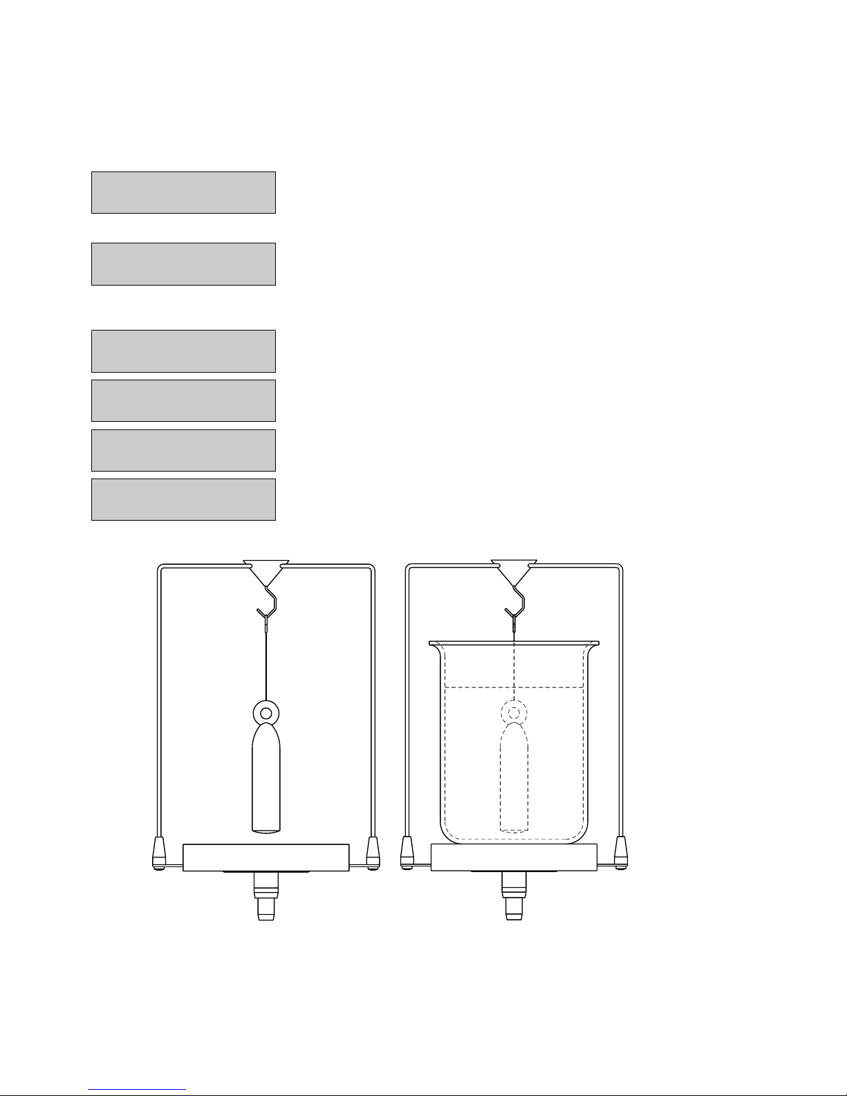
14.5 Density of a liquid "MODE LIQUID" (with density kit 350-8515)
This method is used to determine the density of a liquid. A glass vessel is used for this with a volume of 10
cm
3
or 100 cm3.
fig. 1 fig. 2
Display Key Step
0,000 9
«T» Taring
AIR SET
Hang the glass vessel from the below-balance hook (fig. 1).
+ 24,971 9
«B»
As soon as the reading is stable, it is saved and displayed for 2 seconds.
AIR SET
Place the container and liquid on the balance and lower in the glass vessel (the glass vessel must not touch
the bottom) (fig. 2).
+ 14,985 9
«B»
As soon as the reading is stable, it is saved and displayed for 2 seconds.
LIQUID SET
+ 0,9999 9.ccm
Liquid density display
(provided it is within the 0,5 - 2.0 g/ccm range).
DENSITY <->
+0,20%
«C»
Switch to the density index display
(if Index is ON).
INDEX <->
0,000 9
«T»
Taring, the balance returns to the gram display and is
ready for the next determination.
AIR SET
Page 41
14 Density ("DENSITY") ■
39
English
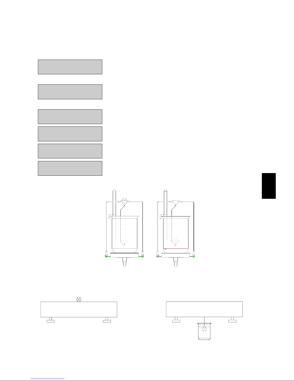
14.6 Density of a solid "MODE SOLID IN AIR"
This method is used to determine the density of a solid. The double beaker is required for this. The
thermometer is used to monitor the temperature of the test liquid in the container.
Density determination using a density determination set Order number see Accessories series 320
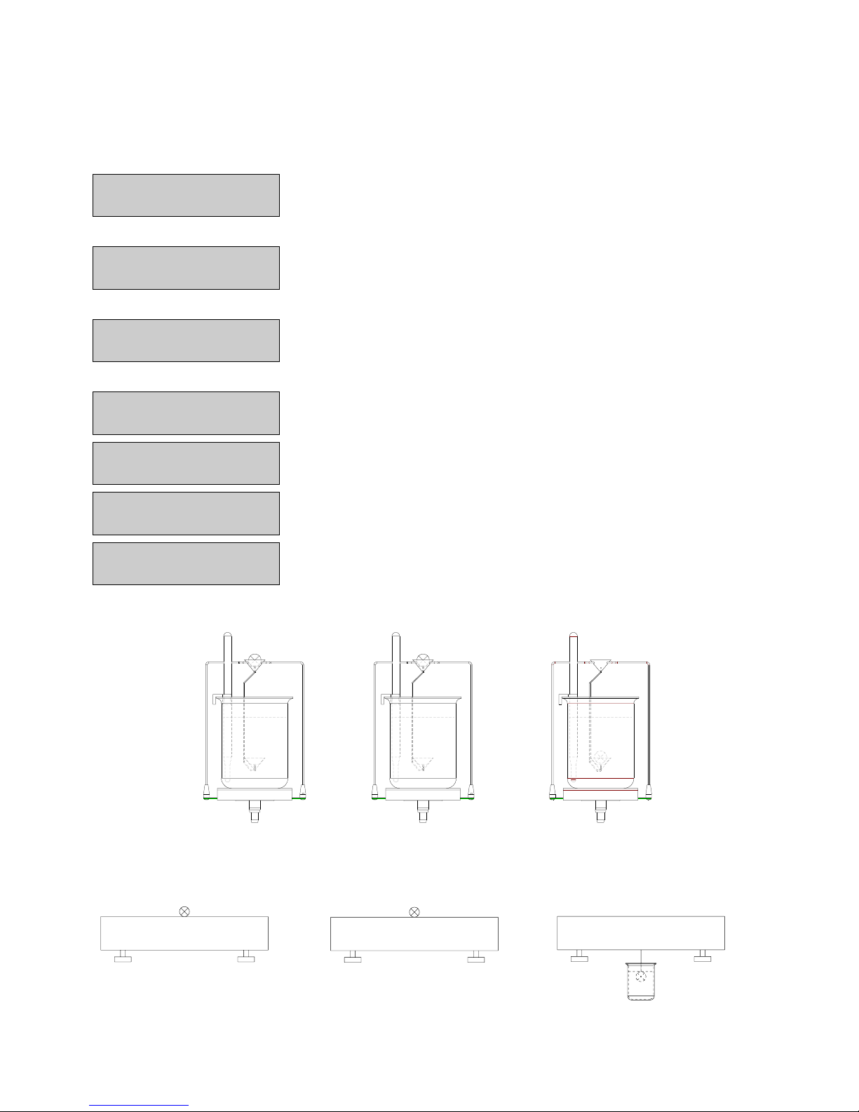
fig. 3 fig. 4
Density determination using below balance weighing Order number see Accessories of the respective
series
fig. 3a fig. 4a
Display Key Step
0,000 9
«T» Taring
AIR SET
Place the solid into the top beaker (fig. 3 resp 3a).
+ 24,972 9
«B»
As soon as the reading is stable, it is saved and displayed for 2 seconds.
AIR SET
Place the solid into the bottom beaker (fig. 4 resp 4a).
+ 16,982 9
«B»
As soon as the reading is stable, it is saved and displayed for 2 seconds.
LIQUID SET
+ 3,120 9.ccm
Solid density display
(provided it is within the 0,1 - 25.0 g/ccm range).
DENSITY <->
+2,05%
«C»
Switch to the density index display
(if Index is ON).
INDEX <->
0,000 9
«T»
Taring, the balance returns to the gram display and is
ready for the next determination.
AIR SET
Page 42
■ 14 Density ("DENSITY")
40
14.7 Density of a porous solid "MODE SOLID POROUS"
This method is used to determine the density of a porous solid. The double beaker is required for this. The
thermometer is used to monitor the temperature of the test liquid in the container.
Density determination using a density determination set Order number see Accessories series 320
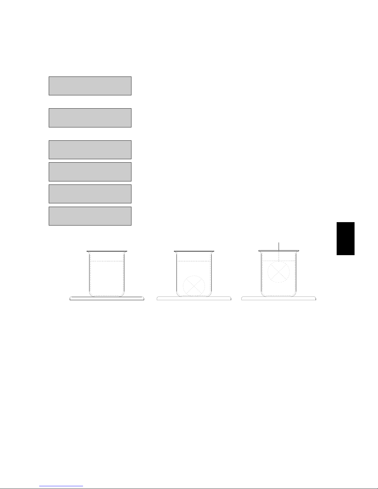
fig. 5fig. 6fig. 7
Density determination using below balance weighing Order number see Accessories of the respectiv
series
fig. 5a fig.6a fig. 7a
Display Key Step
0,000 9
«T» Taring
AIR SET
Place the porous solid into the top beaker (fig. 5 resp 5a).
+ 24,974 9
«B»
As soon as the reading is stable, it is saved and displayed for 2 seconds.
AIR SET
Seal the pores on the solid with wax, for example. Now place the solid into the top beaker (fig. 6 resp 6a).
+ 26,971 9
«B»
As soon as the reading is stable, it is saved and displayed for 2 seconds.
CLOSED PORES SET
Place the solid into the bottom beaker (fig. 7 resp 7a)
+ 16,984 9
«B»
As soon as the reading is stable, it is saved and displayed for 2 seconds.
LIQUID SET
+2,4969.ccm
Solid density display
(provided it is within the 0,1 - 25.0 g/ccm range).
DENSITY <->
+2,05%
«C»
Switch to the density index display
(if Index is ON).
INDEX <->
0,000 9
«T»
Taring, the balance returns to the gram display and is
ready for the next determination.
AIR SET
Page 43
14 Density ("DENSITY") ■
41
English
14.8 Density of a solid "MODE SOLID ON THE BOTTOM"
This method is used to determine the density of a solid; however, no auxiliary apparatus is required. The
thermometer is used to monitor the temperature of the test liquid.
fig. 8 fig. 9 fig. 10
Display Key Step
0,000 9
«T»
Pour the tempered reference liquid (water) into a container, place it on the balance and tare it (fig. 8)
BOTTOM SET
Place the solid in the bottom of the container (fig. 9).
+ 24,971 9
«B»
As soon as the reading is stable, it is saved and displayed for 2 seconds.
BOTTOM SET
Then raise the solid off the bottom, making sure it is still be fully immersed in the test liquid (fig. 10).
+ 9,988 9
«B»
As soon as the reading is stable, it is saved and displayed for 2 seconds.
LIQUID SET
+ 2,496 9.ccm
Solid density display
(provided it is within the 0,1 - 25.0 g/ccm range).
DENSITY <->
+7,36%
«C»
Switch to the density index display
(if Index is ON).
INDEX <->
0,000 9
«T»
Taring, the balance returns to the gram display and is
ready for the next determination.
BOTTOM SET
Page 44
■ 15 Differential weighing ("DIFF.-WEIGHT")
42
15 Differential weighing ("DIFF.-WEIGHT")
15.1 Explanatory notes on differential weighing
In the application differential weighing, samples are investigated for weight changes, the results logged in a
report and collated in statistics.
In differential weighing the original weight of a sample is determined at the start of a measurement.
Following the treatment of the sample, e.g. drying, ashing, vapor-depositing, coating, etc., the sample is reweighed, and the balance determines the difference between the two measurements. Each sample can be
re-weighed up to three times. There is a selection of different units available for the display of the results.
Up to 500 samples can be measured, divided into a maximum of 10 groups. Statistics are compiled for each
individual group.
There are four semi-automatic measuring sequences available for recording the measurements:
– Individual measuring sequence
Record complete sample details with the tare weight, original weight and residual weight(s). Then move
on to the next sample.
– Group 1 measuring sequence
Record the tare weight and original weight of all the samples in a group at the start. Then determine all
the residual weights for a sample and, after that, measure the residual weights for the next sample.
– Group 2 measuring sequence
Record the tare weight and original weight of all the samples in a group at the start. Then determine the
first residual weight for all the samples, followed by the second residual weight for all the samples, etc.
– Series measuring sequence
First of all enter the tare weights of all the samples in the group, then record the original weights of all
the samples and, after that, re-weigh all the samples.
15.2 Selecting the differential weighing application
In order to activate the application menu, press the «MENU» key and select the "DIFF.-WEIGHT" application.
The submenus which are required for defining the differential weighing are now displayed in the "SETUP
APPLICATION" menu.
15.3 Configuring the differential weighing
Various user-specific settings for the application differential weighing can be defined in the menu under
"SETUP APPLICATION".
15.3.1 Overview
• SELECT APPLICATION
SET APP. OFF
...
...
DIFF.-WEIGHT
...
...
Normal weighing mode
...
...
Differential weighing
...
...
•SETUP
APPLICATION
DIFF.-WEIGHT GROUP 1
NAME nnn
MODE SINGLE
GROUP1
GROUP2
SERIES
TARE WEIGHING ON/OFF
Page 45
15 Differential weighing ("DIFF.-WEIGHT") ■
43
English
"GROUP"
Setting for the current group; 10 groups are possible.
The maximum of 500 samples which are possible can be freely distributed to the individual groups.
"NAME"
Definition of the group name with up to 10 characters. If all the samples in a group are deleted, the name
of the group remains. The group name can only be deleted or changed in the menu under "SETUP
APPLICATION".
"MODE"
There is a selection of four different measurement recording options (see chapter 15.4.1 "Mode,
measurement recording").
"TARE WEIGHING"
Switching off the tare measurement. If the tare measurement function is switched off, this applies to all the
measured samples.
"UNIT"
Setting for the unit in which the differential weight is to be calculated (see chapter 15.3.2 "Units").
"DECIMALS"
Definition of the number of decimal places to be shown in the result. The "WEIGHT LOSS" unit is displayed
with the setting for the balance's current unit of weight.
"FACTOR"
Entry of the factor with which the difference in weight is to be offset. This option is only activated if the
"CALCULATED" unit is selected.
"MODE"
Calculation method selection.
– Multiplying the factor by the difference between the original weight and the residual weight.
– Dividing the factor by the difference between the original weight and the residual weight.
This option is only activated if the "CALCULATED" unit is selected.
"SET PRINT FORMAT"
Definition of the report. The options marked "ON" are contained in the report and are printed (see chapter
15.4.6 "Report").
15.3.2 Units
The result of a differential weighing is displayed and printed for all the samples in the set unit. If the unit is
changed, the analysis changes the calculation of the results for all the samples which have been measured
previously. The selected unit is also used for the statistical analysis of a group.
UNIT WEIGHT LOSS
LOSS %
RESIDUAL %
ATRO 1
ATRO 2
CALCULATED
in the current unit of weight
DECIMALS 2
FACTOR n.nnn e+n only if the "CALCULATED" unit has been
selected
MODE F * DIFF.
F / DIFF.
only if the "CALCULATED" unit has been
selected
SET PRINT FORMAT SAMPLE ID ON/OFF
TIME ON/OFF
TARE ON/OFF
INITAL ON/OFF
RESIDUAL ON/OFF
Page 46
■ 15 Differential weighing ("DIFF.-WEIGHT")
44
Calculation of the units:
I: Original weight R: Residual weight F: Factor
15.4 Working with differential weighing
Press «F» briefly to go to differential weighing.
Configuration of the function keys:
Unit Calculation
"WEIGHT LOSS":
"LOSS %" (loss in percent):
"RESIDUAL %" (residue in percent):
"ATRO 1" (dry mass):
"ATRO 2" (moisture):
"CALCULATED" (calculated with a factor F):
or
Main menu differential weighing
SET GET DEL STA
Key Functions
«SET»
To start the measurement recording for the set group.
In the case of an empty group, start with the first sample. If samples have already
been recorded in this group, start from the position where the measurement recording
process was interrupted.
«GET»
To get a measured sample.
The set mode is switched to single until «GET» is exited by pressing the «esc» key.
The selected sample is started from the position where the measurement recording
process was interrupted.
«DEL»
Activates the Delete submenu.
The user can delete individual samples, a whole group or all the read samples (see
chapter 15.4.4 "Deleting samples, groups").
«STA»
To get a measured sample.
The set mode is switched to single until «STA» is exited by pressing the «esc» key.
The selected sample is started from the position where the measurement recording
process was interrupted.
IR–()–
IR–
I
------------100%⋅–
R
I
----100%⋅
I
R
----100%⋅
IR–
R
------------100%⋅–
IR–()F⋅
F
IR–
------------
Page 47
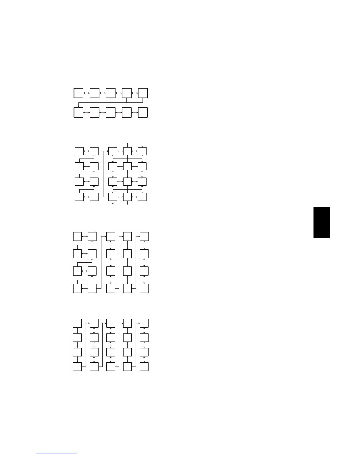
15 Differential weighing ("DIFF.-WEIGHT") ■
45
English
15.4.1 Mode, measurement recording
There are four different options available for semiautomatic measurement recording.
Key:
T: Tare I: Original weight R1-R3: Residual weight 1-3
Single
Group 1
Group 2
Series
Navigation
The differential weighing program works with semiautomatic measurement recording. Once one value has
been measured, the program automatically navigates to the next one.
The user can navigate between the measured values using the arrow keys , as shown by the arrows in the
graphics. If a reading has been measured incorrectly, the user can navigate back to it with the arrow keys
provided this navigation is possible (see the graphic for the set mode).
The tare weight, original weight and residual
weight are recorded in consecutive order for each
sample. Once the measurements for one sample
have ended, the next one can be started.
The tare weight and original weight for each
sample are recorded at the start. The residual
weights are then measured for all the samples.
The tare weight and original weight for each
sample are recorded at the start. Then determine
the first residual weight for all the samples,
followed by the second residual weight for all the
samples, etc.
The tare weight is measured for each sample at
the start. Then record the original weight for all
the samples and, after that, re-weigh all the
samples.
T I R1 R2 R3
T I R1 R2 R3
T I R1 R2 R3
T I R1 R2 R3
T I R1 R2 R3
T I R1 R2 R3
T I R1 R2 R3
T I R1 R2 R3
T I R1 R2 R3
T I R1 R2 R3
T I R1 R2 R3
T I R1 R2 R3
T I R1 R2 R3
T I R1 R2 R3
Page 48
■ 15 Differential weighing ("DIFF.-WEIGHT")
46
If a reading has not been taken, the user cannot move on to the next one yet.
Navigation in single mode
The navigation for residual weights 2 and 3 must be done manually. The user gets to the next sample by
pressing the «
D» key.
Navigation in group 1 mode
The automatic navigation switches from tare weight to original weight for sample 1, followed by the tare
weight and then original weight for sample 2, etc. Once all the original weights for the group have been
measured, the user can switch to residual weight 1 for the first sample by pressing the «B» key.
The navigation for residual weights 2 and 3 must be done manually, which is also the case for switching to
residual weight 1 for the next sample.
Once residual weights 1 or 2 for the last sample have been measured, the user can move on to residual
weights 2 or 3 for the first sample by pressing the «
D» key.
Navigation in group 2 mode
As in group 1 mode, the automatic navigation switches from tare weight to original weighting for sample 1,
followed by the tare weight and then original weight for sample 2, etc. Once all the original weights for the
group have been measured, the user can switch to residual weight 1 for the first sample by pressing the «B»
key.
Subsequent navigation takes place automatically until all the readings in the group have been measured.
Navigation in series mode
Automatic navigation switches from tare sample 1 to tare sample 2, etc. Once all the tare weights for the
series have been measured, the user can switch to the original weight for the first sample by pressing «B».
Subsequent navigation takes place automatically until all the readings in the series have been measured.
Press «esc» to return to the main menu.
15.4.2 Measurement
A differential weighing sequence is explained on the basis of an example. The balance must be switched on,
and the application differential weighing must be activated.
During the measurement, the right «T» key corresponds to the «E» key and is used to accept the
measurement. The left «T» key is required to tare the balance.
Measurement line:
Display the gross weight. The active balance unit is used as the weight unit.
Info line:
"1-2": Number of the current group (1) and sample number (2)
"T": Weight reading (tare) being measured
"+ 0.00015 g": The weight reading displayed always corresponds to the net weight of the sample.
"GROUP 1" mode is set and group 1 selected for the example. There are no samples in the selected group
1 yet. The result is indicated in the "LOSS %" unit with 2 decimal places.
+ 0.00015 9
Measurement line
1-2 t + 0,00015 9 Info line
Display Key Step
«A» Start the differential weighing.
SET GET DEL STA
+ 0,00015 9
«T»-left If necessary, tare the balance.
1-1 t + 0,00015 9
The right «T» key corresponds to «E» and is used to accept the measurement reading.
+ 0,00000 9
Measure tare value 1,
i.e. place on an empty container 1.
1-1 t + 0,00000 9
Page 49
15 Differential weighing ("DIFF.-WEIGHT") ■
47
English
15.4.3 Sample information
The user can switch to the info display for the current sample during the measurement recording by pressing
«
F».
Configuration of the function keys:
+ 15,85000 9
«E» Accept tare weight 1.
1-1 t + 15 ,85000 9
+ 15,85000 9
Fill container 1 with original weight 1 and place it on.
1-1 I + 0,00000 9
+ 56,10000 9
«E» Accept original weight 1.
1-1 i + 40,25000 9
As group 1 mode is set, the program automatically switches to the tare measurement for sample 2. Remove original
weight 1 from the weighing pan and, if necessary, tare the balance.
+ 0,00000 9
Measure tare weight 2, i.e. place on empty container 2.
1-2 t +0.00000 9
+ 15,87504 9
«E» Accept tare weight 2.
1-2 t + 15 ,87504 9
+ 15,87504 9
Fill the container with original weight 2 and place it on.
1-2 I + 0,00000 9
+ 54,53186 9
«E» Accept original weight 2.
1-2 i + 38,65682 9
As group 1 mode is set, the program switches automatically to the tare measurement for sample 3.
+ 54,53186 9
«B» Switch to residual weight 1 for the first sample.
1-3 t + 54 ,53186 9
If necessary, tare the balance. The negative weight reading in the info line corresponds to tare weight 1.
+ 0,00000 9
Place residual weight 1 for the first sample (including
the container) on the balance.
1-1 r1 - 15,85000 9
+ 50,32364 9
«E» Accept residual weight 1.
1-1 r1 + 34.57364 9
- 14,10 %
Display the result of residual weight 1. (Loss in
percent). Print out the sample report.
1-1 diff1
In order to measure a second residual weight for the same sample, press the «B» key. In order to determine the
residual weight 1 in the second sample, press the
«D» key.
Key Functions
«A», «B»
In the measurement display: switch between the readings shown
In the results display: switch back to the measurement display
«
C»
«
D»
If a residual weight is displayed: switch to the results display
In the results display: switch to the result unit
«esc» Exits the info display
«PRINT»
Prints the sample info, including all the measurement readings
The result is printed in all the units (see chapter 15.4.6 "Report").
Display Key Step
Page 50
■ 15 Differential weighing ("DIFF.-WEIGHT")
48
15.4.4 Deleting samples, groups
Press the «DEL» function key to go to the Delete submenu in the main menu.
Configuration of the function keys:
Press «esc» to exit the deleting process at any time without deleting.
15.4.5Statistics
Press the «STA» function key to go to the Statistics submenu in the main menu.
Configuration of the function keys:
15.4.5.1Statistics printout
Configuration of the function keys:
15.4.6 Report
The differential weighing report is printed after every residual weighing. Individual options in the report can
be switched on and off.
If the «PRINT» key is pressed in sample information, the result is output in all the units.
If the «PRINT» key is pressed during the recording of the measurements, the current weight is printed in the
- - - - - - - -
Delete submenu
-S- -G- ALL
Key Functions
«-S-»
Delete a single sample.
The sample to be deleted can be selected by pressing the «
C», «D» keys. The sample
is selected by pressing the «E» key.
«-G-»
Delete all the samples in the selected group.
The group to be deleted can be determined by pressing the «
C», «D» keys. The group
is selected by pressing the «E» key.
«ALL»
Delete all the saved samples.
As a safeguard, the deleting process must be confirmed by selecting "YES" and
pressing «E». Nothing is deleted if the user selects "NO" or presses «esc».
- - - - - - - -
Statistics submenu
Gx -V- -R- ALL
Key Functions
«-Gx-»
Select the group for which statistics are to be compiled. "x" indicates the active
group.
«-V-»
Prints the measurement readings for all the samples in the selected group. The result
is only printed in the unit which is set.
«-R-» Prints the statistics on the results for the selected group.
«ALL» Starts the Statistics printout submenu.
- - - - - - - -
Statistics printout submenu
STD PC
Key Functions
«STD»
Prints the measurement readings for all the samples and the statistics on the results
for the selected group. The result is only printed in the unit which is set.
«PC»
Prints measurement readings and statistics on all the samples in the selected group in
tabular form. The individual values are separated by a tab.
Page 51
15 Differential weighing ("DIFF.-WEIGHT") ■
49
English
current unit. If the result is displayed, the differential weighing report is printed.
The statistics output with the options which can be selected.
If no statistics can be compiled on the residual weight, only the number of values is output. A minimum of
2 values is required for statistics.
15.4.7 Remote control commands
Date 10.04.2004 Time 10:05:30
Date and time, if they are switched on. (Can be set in the Configuration menu)
Name : XR 125 SN
Software : V00-0000 P00
Serialno : 3300-001
Balance ID, if it is switched on. (Can be set in the Configuration menu)
Sample : 1-1
Sample ID, if it is switched on.
Tare : + 15.85000 g
Time : 08:15:25 10.04.04
Tare and time, if they are switched on.
Initial : +40.25000 g
Time : 08:16:32 10.04.04
Original weight and time, if they are switched on.
Residual 1 : +34.57364 g
Time : 09:48:12 10.04.04
Residual weight 1 and time, if they are switched on.
Lost : + 14.10 %
Result of the differential weighing
User : MUSTER
Operator ID, if this is switched on. (Can be set in the Configuration menu)
Date 10.04.2004 Time 10:05:30
Date and time, if they are switched on. (Can be set in the Configuration menu)
Name : XR 125 SN
Software : V00-0000 P00
Serialno : 3300-001
Balance ID, if it is switched on. (Can be set in the Configuration menu)
Group : 1
Group name; if there is no group name defined, the number is output.
Residual 1:
Values : 2
Mean : - 45.95 %
StdE : + 5.93 %
StdE% : - 12.90 %
Max : - 41.76 %
Min : - 50.14 %
Statistics on residual weight 1
Residual 2:
Values : 1
Statistics on residual weight 2
Residual 3:
Values : 0
Statistics on residual weight 3
User : MUSTER
Operator ID, if this is switched on (Can be set in the Configuration menu)
Command Function
ADWSTATE
Returns the status of the sample memory.
-Number of samples saved
-Number of samples still to be saved
-Number of samples per group
ADWx y
Prints the entire statistics, with measured values, on one or all of the groups.
x defined the format.
x = 0 standard format
x = 1 PC format (separated by tabs)
y indicates the group.
y = 0 all groups
y = 1..10 group y
Page 52

■ 16 Minimum original weight ("MIN.-WEIGHT")
50
16 Minimum original weight ("MIN.-WEIGHT")
16.1 Explanatory notes on the minimum sample weight application, MSW
MSW application is a minimum original weight solution which enables you to fulfill QM guidelines, such as
GLP, GMP or USP.
16.1.1 Minimum original weight and quality management
Only very small quantities are used in many applications and, thus, only a small part of the balance's
weighing capacity is used. However, the lower the original weight, the greater the relative measuring
uncertainty.
What is the minimum original weight necessary to enable the quality management tolerance limits to be
complied?
The minimum original weight which is required is determined on the basis of the QM criteria and of the
statistical data from repeated weighing procedures.
If the weight is below the minimum original weight, a warning appears on the balance display warning you
of this; these values are also marked in the printout.
–The requisite minimum original weights should be elicited on the basis of the QM specifications by means
of the statistical analysis of certain series of measurements.
(The balance's own "STATISTIC" function could be used for this purpose, for example. It is used to
perform and subsequently log the requisite series of measurements.)
– Once the minimum original weight(s) has/have been determined, it/they can be input into the balance.
Up to three tare ranges can be defined with the corresponding minimum original weights.
The balance's weighing modes, as well as measuring time and stability, are also fixed in such a way as
to guarantee compliance with tolerances in future measurements.
Tare ranges, minimum original weights and weighing modes cannot be changed by the user.
– The values which are input can be logged by means of an application status print and could, along with
the report on the statistical measurement series, be used as a QM certificate.
If work is performed on the basis of the minimum original weight application, this serves to ensure that
the weighing results conform to the certificate specifications and, thus, to your QM guidelines.
16.2 Selecting the minimum original weight application
In order to activate the application menu, press the «MENU» key and select the "MIN.-WEIGHT" application.
The submenus which are required for defining the minimum original weight are now displayed in the "SETUP
APPLICATION" menu.
• SELECT APPLICATION
SET APP. OFF
...
...
MIN.-WEIGHT
...
...
Normal weighing mode
...
...
Minimum original weight
...
...
Page 53
16 Minimum original weight ("MIN.-WEIGHT") ■
51
English
16.3 Configuring the minimum original weight
16.3.1 Variable menu settings
"INFO LINE"
– ON: The minimum original weight appears permanently in the balance display.
"Value under minimum original weight" is symbolized by a "P" in the balance display.
– OFF: The minimum original weight only appears in the balance display while "value under minimum
original weight".
"ZERO KEY"
The reset function is assigned to the «
C» key.
This function can be used to reset the weight display to zero, although the minimum original weight which
was valid previously is retained (see chapter 16.4.3 "Resetting with the function key «>0<»").
"SET PRINT FORMAT" – "MIN. WEIGHT"
The minimum original weight appears additionally in the measurement printout.
16.3.2 Non-variable menu settings
"CODE"
This authorization code (four-digit number) enables the relevant person to change the following menu
settings.
"FLOATINGDISPLAY"
This value relates to the quality of the balance location and must be set correctly in order to achieve
optimum, reproducible results. Select:
– Optimum balance location: "FLOATINGDISPLAY 0.04" or "FLOATINGDISPLAY 0.08"
– Good balance location: "FLOATINGDISPLAY 0.16"
– Critical balance location: "FLOATINGDISPLAY 0.32"
"STABILITY"
This value relates to the quality of the balance location and must be correctly set in order to achieve
optimum, reproducible results. Select:
– Optimum balance location: "STABILITY LOW"
– Good balance location: "STABILITY MEDIUM"
– Critical balance location: "STABILITY HIGH"
"NEXT TEST"
Indicates the date until which the set minimum original weights are deemed to be valid, or when the
minimum original weights need to be re-determined by the quality coordinator(s).
They should be re-determined periodically in accordance with your QM specifications. This is also advisable
•SETUP
APPLICATION
MIN.-WEIGHT
INFO LINE ON/OFF
Display the info line permanently
ZERO KEY ON/OFF
Facilitate resetting
SET PRINT FORMAT MIN. WEIGHT ON/OFF
VIEW / SET PARAMETERS
(CODE - - - - )
FLOATINGDISPLAY 0.16
STABILITY MEDIUM
NEXT TEST 18 .01.05
TEST-PARA. k=3 U=0.1%
RANGE 1 35.00000 g
MIN.WGT 1 0.07500 g
RANGE 2 85.00000 g
MIN.WGT 2 0.10500 g
RANGE 3 125.00000 g
MIN.WGT 3 0.13500 g
(CODE NEW - - - - )
NOTE
Factory-set authorization code: 1452 / New code: ______
Page 54
■ 16 Minimum original weight ("MIN.-WEIGHT")
52
if there is a decisive change in the weighing criteria (ambient and application conditions).
Once the date has elapsed, a warning briefly appears in the balance display when the MSW application is
started.
"TEST-PARA."
You can enter a text here which describes the parameters which you have used for determining the minimum
original weight (extension factor, uncertainty).
"RANGE" / "MIN.WGT. 1-3"
Up to 3 tare ranges (the upper limit is specified in each case) can be defined with the corresponding minimum
original weights.
"CODE NEW"
New code definable (four-digit number).
16.4 Working with the minimum original weight
Press «F» briefly to go to the minimum original weight.
Configuration of the function keys:
16.4.1 Indicator for "value below minimum original weight"
16.4.1.1 Indicator in the balance display "MIN= ..." or "P" or
• "INFO LINE OFF"
• "INFO LINE ON"
16.4.1.2 Indicator in the report printout ("*")
• "SET PRINT FORMAT" – "MIN. WEIGHT OFF"
0.00000 9 p
Display in the minimum original weight
MIN=0.07500 >0<
Key Functions
«MIN=...»
Additional information on the minimum original weight is displayed at 2-second
intervals
«>0<»
Resetting the weight display without changing the value of the minimum original
weight.
+ 0.01532 9
Minimum original weight has not been reached yet
MIN=0.07500
+ 0.07874 9
Minimum original weight has been reached
+ 0.01532 9 p
Minimum original weight has not been reached yet
MIN=0.07500
+ 0.07874 9
Minimum original weight has been reached
MIN=0.07500
* +0.01532 g
Minimum original weight has not been reached yet
+0.07874 g
Minimum original weight has been reached
Page 55
16 Minimum original weight ("MIN.-WEIGHT") ■
53
English
• "SET PRINT FORMAT" – "MIN. WEIGHT ON"
16.4.2Displaying additional information with the function key «MIN...»
Normal display ("INFO LINE OFF", "ZERO KEY OFF"):
Working sequence if «MIN=...» («A») is pressed (displayed for 2 seconds):
16.4.3Resetting with the function key «>0<»
Display in the event of "ZERO KEY ON":
Printout:
• Using the resetting:
If you reset the balance display using the tare key «T», the balance automatically determines the tare range
of the tare weight, which is placed on, and sets the minimum original weight in accordance with this range.
If you now reset the display in a series of weighing procedures with identical or similar tare weights between
weighing procedures and ensure that the same minimum original weight is set at all times, use the "ZERO
KEY" «>0<» instead of the tare key.
16.5 Determining the minimum original weight periodically
The minimum original weight is dependent on the ambient conditions. Therefore, it must be determined onsite and must be reviewed periodically.
The following parameters influence the minimum original weight:
• Repeatability:
The repeatability is determined by the standard deviation of the balance on-site. It is determined by the
ambient conditions, the nature of the goods being weighed and the balance settings.
• Tare weight
• Relative uncertainty (U):
The tolerable uncertainty is determined by the user or defined by standards.
Min.Wgt. : 0.07500 g
Actual : *+ 0.01532 g
Minimum original weight has not been reached yet
Min.Wgt. : 0.07500 g
Actual : + 0.07874 g
Minimum original weight has been reached
+ 0.00000 9
Minimum original weight
MIN=0.07500
+ 0.00000 9
Current tare
aCt. tarE= 3.45136
then:
+ 0.00000 9
Maximum tare for which the displayed minimum original weight
applies
max. tarE= 35.00000
+ 0.00000 9 p
Resetting took place in an identical tare range to the previous one.
MIN=0.07500 >0<
+ 0.000009 p
Resetting took place in a different tare range to the previous one.
The minimum original weight in the new tare range would actually be smaller
(<).
MIN<0.07500 >0<
Min. Wgt. : > 0.07500 g
Actual : * 0.00000 g
I.e. the logged minimum original weight is actually too large or the
requisite minimum original weight would actually be smaller (see display
above).
Page 56

■ 16 Minimum original weight ("MIN.-WEIGHT")
54
• Extension factor (k) (generally 2 or 3):
The extension factor determines the likelihood of occurrence. The factor is defined by the user or is
defaulted.
The minimum original weight is calculated as follows:
Example of figures for the MSW in accordance with the USP:
If work is conducted in accordance with the USP (United States Pharmacopoeia), the following parameters
are given:
• Repeatability:
Standard deviation if the same weight is placed on ten times.
• Extension factor:
k=3
• Rel. uncertainty:
U=0.1%
The repeatability of an XR125SM in the tare range between 0 and 35 g was determined as a standard
deviation on site by placing a weight on ten times and measures 0.025 mg.
The minimum original weight is thus calculated as follows:
In compliance with USP24-NF19, the original weight on the XR125SM may not be less than a minimum of
75 mg.
Recommended procedure:
– Conduct the tests on-site and as close to the real situation as possible.
– Try to provide the best possible ambient conditions.
Ensure that these conditions do not deteriorate significantly afterwards in normal operation.
– First of all, configure the "FLOATINGDISPLAY" and "STABILITY" weighing modes (see chapter 16.3.2
"Non-variable menu settings").
– Define the due-date for the next check, "NEXT TEST", in accordance with your QM specifications.
– Define the extension factor and relative uncertainty in accordance with your QM specifications and
describe this under "Test parameters". The test parameters are merely for information purposes.
– Determine the minimum original weight(s) for your balance as follows:
Determining repeatabilities / Defining tare ranges:
First of all, test the behavior of the balance in different tare ranges:
Divide the balance's weighing range into 10g intervals, for example, and measure the repeatability for
each interval.
Draw a graph of the entire weighing range by plotting all the results, joining them together and working
Min. Weight[MIN]
Extension factor[k] Standard deviation[StdD]⋅
Relative uncertainity[U]
----------------------------------------------------------------------------------------------------------------=
Min. Weight[MIN]
3 0.025 mg⋅
0.1%
------------------------------ 100% 75 mg=⋅=
Page 57
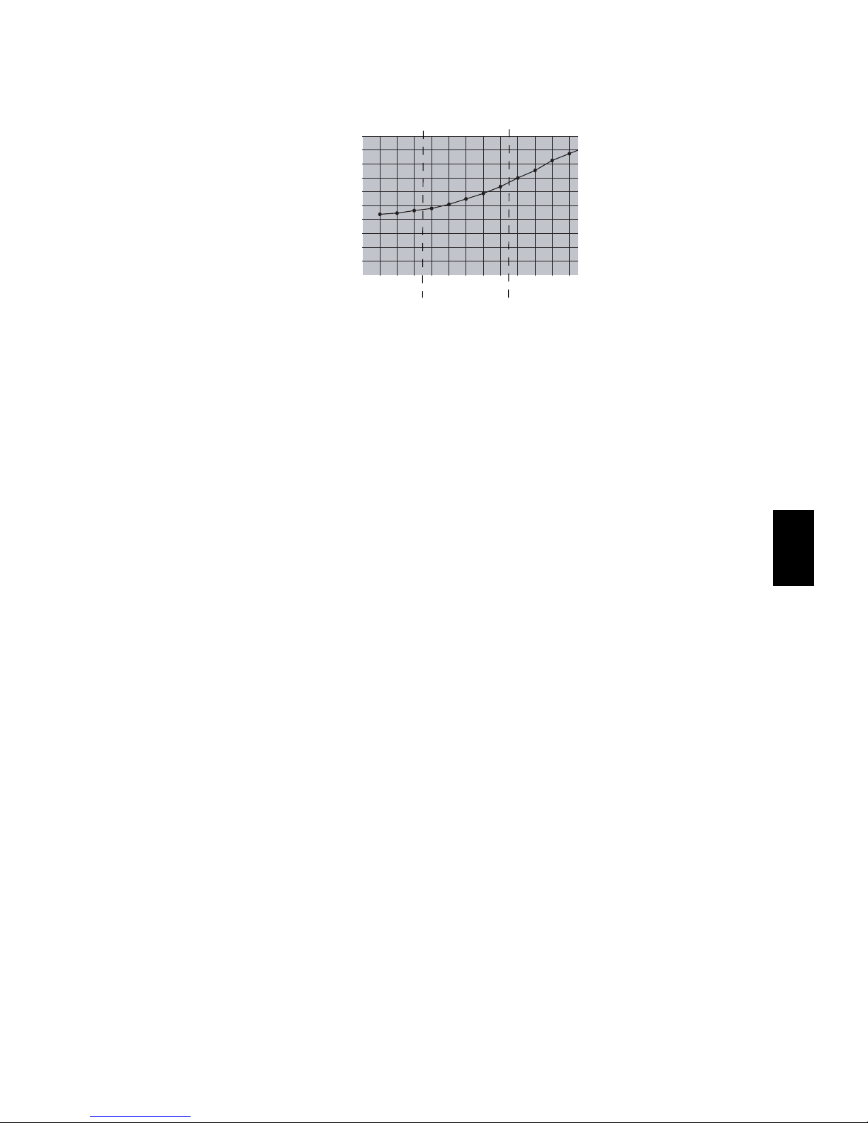
16 Minimum original weight ("MIN.-WEIGHT") ■
55
English
out the mean:
– On the basis of this graph it is relatively easy to define the max. 3 ranges with the corresponding
repeatabilities. (If you know which tare weights are typically used, you can optimize the tare ranges in
terms of these typical weights.)
Measuring the repeatability (StdD) with the aid of "STATISTIC": Apply the relevant tare weight
permanently to the balance and tare it. Conduct the measurement series with a net weight of approx. 1g:
– 1: + 1.00287 g Example of how the STATISTIC function is used.
2: + 1.00291 g
........
9: + 1.00288 g
10: + 1.00290 g
–Values:
Mean : + 1.00289 g
StdE : + 0.000022 g
StdE % : 0.00 %
Max : + 1.00293 g
Min : + 1.00287 g
– Calculating the minimum original weight(s):
Now calculate the minimum original weights using the equation shown above, on the basis of the
repeatabilities belonging to the tare ranges.
– Configure the balance with the determined values.
0.000
0.005
0.010
0.015
0.020
0.025
0.030
0.035
0.040
0.045
0.050
0 10 20 30 40 50 60 70 80 90 100 110 120
Tare weight [g])
StdD= 0.025mg
MIN= 75mg
StdD= 0.045mg
MIN= 135mg
StdD [mg])
Calculate:
(k=3, U= 0.1%
StdD= 0.035mg
MIN= 105mg
Page 58
■ 17 Dynamic weighing ("DYN.-WEIGHT")
56
17 Dynamic weighing ("DYN.-WEIGHT")
17.1 Introduction to the dynamic weighing application
The "DYN. WEIGHT" workflow supports accurate weighing on an unstable surface, e.g. on board ships.
During the period of measurement defined by the user in the setup menu, the balance measures
continuously, calculates the mean of the saved values at the end of the period of measurement and indicates
the average measurement value which this yields.
17.2 Selecting the dynamic weighing application
In order to activate the application menu, press the «MENU» key and select the "DYN. WEIGHT" application.
The submenus which are required for defining the dynamic weighing are now displayed in the "SETUP
APPLICATION" menu.
17.3 Configuring dynamic weighing
In the setup, specify the period of measurement over which the mean is to be calculated.
17.4 Dynamic weighing
Press «F» briefly to go to dynamic weighing.
Configuration of the function keys:
• SELECT APPLICATION
SET APP.OFF
...
...
DYN. WEIGHT
...
...
Normal weighing mode
...
...
Dynamic weighing
...
...
•SETUP
APPLICATION
DYN. WEIGHT
MEASURETI ME 4
Enter the period of time in seconds
67,8907 9
Display during dynamic weighing
MAN AUTO TARE STO
Key Functions
«MAN» Manual activation of the measurement.
«AUTO» Automatic activation of the measurement with a 1-second delay.
«TARE»
Determine the tare over the period of measurement and save it for other
measurements.
«STO» Statistics and storage function if statistics are activated.
Page 59
18 Pipette calibration ("PIPETTE") ■
57
English
18 Pipette calibration ("PIPETTE")
18.1 Introduction to pipette calibration
Quality management systems require volumetric measuring equipment to be checked regularly. This
application allows you to check pipettes of any make by means of a gravimetric method.
You require a thermometer and a barometer in order to conduct this.
During the pipette test, the sample volume is always derived from the sample weight. The density of the test
liquid (distilled water) and the buoyancy are taken into account during conversion.
The pipette application supports up to 20 pipettes. By simply selecting the pipette you require, its
specifications are loaded into the application. You can then commence the pipette test straight away.
The pipette specification data must be defined once beforehand in accordance with the manufacturer's
details. You can change this at any time later on.
If you wish to adjust the pipette, please consult the pipette manufacturer's instructions.
18.2 Selecting the pipette calibration application
In order to activate pipette calibration, press the «MENU» key and select the "PIPETTE" application.
18.3 Configuring the pipette calibration
In the "SETUP APPLICATION" menu, specify the measuring sequence and define the pipettes. The
tolerances for inaccuracy and imprecision are manufacturer and model-specific. Refer to the pipette
manufacturer's documentation for data.
• SELECT APPLICATION
SET APP. OFF
...
...
PIPETTE
...
...
Normal weighing mode
...
...
Pipette calibration
...
...
•SETUP
APPLICATION
PIPETTE SAMPLES 10
EVAPORATION MEAS. ON/OFF
SET PIPETTES PIPETTE- 1 NAME ttt...
SNO. ttt...
VOL.1 VOLUME 0.00000 ml
INACCUR. <E> 0.0 %
IMPREC. <STDE> 0.0 %
CYCLE TIME 0.0 s
VOL.2 ditto
VOL.3 ditto
PIPETTE- 2 NAME ttt...
SNO. ttt...
VOL.1 VOLUME 0.00000 ml
INACCUR. <E> 0.0 %
IMPREC. <STDE> 0.0 %
CYCLE TIME 0.0 s
VOL.2 ditto
VOL.3 ditto
............... ........ .....
PIPETTE-20 ditto ditto
Page 60
■ 18 Pipette calibration ("PIPETTE")
58
"SAMPLES"
Enter the number of random sample measurements per volume (setting range: 2-50).
"EVAPORATION MEAS."
– ON: The evaporation over the cycle time is automatically determined before the pipetting process
starts, after the tare vessel is placed on, and the pipetting volumes are thus corrected accordingly.
– OFF: The evaporation rate is not taken into account.
"SET PIPETTES"
Select one of the 20 pipettes.
"NAME"
Enter a description for the selected pipette (max. 20 characters).
"SNO."
Enter a serial number for the selected pipette (max. 20 characters).
If a barcode marking on the pipette is used as the serial number, the pipette can be selected directly by
reading in the barcode during the pipette test.
"VOL. 1, 2, 3"
Up to three test volumes can be selected per pipette. Pipettes with a variable volume are normally tested at
10%, 50% and 100% of the maximum volume.
"VOLUME"
Enter the test volume in [ml].
"INACCUR. <E>"
The permissible incorrectness is entered for each volume in terms of [%] of the test volume. The
incorrectness describes the systematic error (setting range: (+/-) 0.1 - 9.9%).
"IMPREC. <STDE>"
The permissible imprecision (standard deviation) is entered for each volume in terms of [%] of the test
volume. The imprecision describes the statistical error (setting range: 0.1 - 9.9%).
CYCLE TIME
The cycle time determines the duration of a single measurement (suck in liquid, discharge, wait for a stable
weighing reading). The weighing reading is adopted at the end of the cycle time. This facilitates reproducible
work. Short cycle times minimize evaporation losses; large volumes require longer cycle times (slow
discharge of the pipette volume) (setting range: 0-120s).
18.4 Working with the pipette
The user can switch between weighing mode and pipette calibration by pressing the «F» key.
Configuration of the function keys:
0,00000 9
Main menu - Pipette
DEMO-P 1.00000 Ml run
Key Functions
«DEMO-P» Pipette selection (can also be selected by means of a barcode reader)
«1.00000 mL»
Select the test volume ("VOL.1" is the default)
(select with «
C» and «D», confirm with «E»)
«RUN» Start the program (see chapter 18.4.1 "Conducting the pipette test")
Page 61
18 Pipette calibration ("PIPETTE") ■
59
English
18.4.1 Conducting the pipette test
Press «esc» to stop the procedure at any time.
The actual pipette measurement starts now:
The result of the pipette test is displayed in the last step:
Display Key Step
- - - - - - - -
«E»
If necessary, change the (starting) temperature
Temperature 22.0C
- - - - - - - -
«E»
If necessary, change the air pressure
AIR PRESS. 1013.0 hpa
0,00000 9
«D»
Place the container with the liquid receiver (distilled water)
on the balance
PLACE CONTAINER OK
The balance is tared automatically. The evaporation measurement then starts if it is activated in the
setup; otherwise, the first sample measurement starts.
+ 0,00009 9
Evaporation measurement running
EVAPORAT. meAs.
COUNTDOWN
- - - - - - - -
«C» or «D»
Evaporation measurement ends. Press «OK» to confirm the
measurement or
«REP» to repeat it, where necessary.
- 0.00016 9 REP OK
Note:
This must result in a reduction in weight! If the reading does not seem plausible, you should repeat the
evaporation measurement.
Display Key Step
- - - - - - - -
The balance is tared automatically.
PUT SAMPLE 1/10
COUNTDOWN
0,00000 9
As soon as 0.00000g appears on the display, the 1st random
sample can be pipetted in.
PUT SAMPLE 1/10
COUNTDOWN
- - - - - - - -
«C» or «D»
1st random sample measurement ended. Press «OK» to
confirm the measurement or
«REP» to repeat it, where
necessary.
+ 0.99428 9 REP OK
- - - - - - - -
The balance is tared automatically.
PUT SAMPLE 2/10
COUNTDOWN
0,00000 9
As soon as 0.00000g appears on the display, the 2nd random
sample can be pipetted in.
PUT SAMPLE 2/10
COUNTDOWN
Perform the process for all n random samples. Rejected samples are not counted; their number is logged.
- - - - - - - -
«C» or «D»
nth random sample measurement ended. Press «OK» to
confirm the measurement or
«REP» to repeat it, where
necessary.
+ 0.99529 9 REP OK
- - - - - - - -
«E»
If necessary, change the (end) temperature
temperature 23.0c
Display Key Step
0,00000 9
«C» or «D»
Pipette test passed.
PASSED inf end
Page 62
■ 18 Pipette calibration ("PIPETTE")
60
Press the «PRINT» key to print out the report on the pipette test or to send it to the PC.
Press «INF» («
C») to display the results on the balance display as well:
Press «END» to exit the measurement series. WARNING: the values are not saved in the balance.
0,00000 9
«C» or «D»
Pipette test failed.
FAILED inf end
Display Key Step
0,00000 9
«C»
Average
MEAN 0.99823 Ml
0,00000 9
«C»
Incorrectness
e. 0.00177 Ml
0,00000 9
«C»
Incorrectness [%]
e.-% - 0.18 %
0,00000 9
«C»
Imprecision as a standard deviation
stdE. 0.00057 Ml
0,00000 9
«C»
Imprecision as a relative standard deviation [%]
StdE.-% 0.06 %
0,00000 9
«C»
Maximum volume
max. 0.99884 Ml
0,00000 9
«C»
Minimum volume
min. 0.99767 Ml
0,00000 9
«C»
1st measurement reading
1= 0.99782 Ml
0,00000 9
«C»
all the other measurement readings follow
_= _._____ Ml
0,00000 9
«C» or «D»
PASSED inf end
Display Key Step
Page 63
18 Pipette calibration ("PIPETTE") ■
61
English
18.4.2 Report
------ PIPETTE-CHECK -------
Date 28.07.2004 Time 10:03:16
Name : XR 125 SM
Software : V00-0000 P00
Serienr : 2601-26
Pipetten-Name : DEMO-PIPETTE
Serie-Nr. : 7610700607077
Test Volume : 1.00000 ml
Inaccuracy (E) : 0.5 %
Imprrecision(StdE) : 0.2 %
Cycle Time : 15 s
Temp. 1 : 22.0 C
Temp. 2 : 23.0 C
Air Pr. : 1013.0 hPa
Evapor. : - 0.00016 ml
Mean : + 0.99823 ml
E : - 0.00177 ml
E % : - 0.18 %
StdE. : + 0.00057 ml
StdE. % : + 0.06 %
Max : + 0.99884 ml
Min : + 0.99767 ml
Values : 10
Reject. : 0
1 : + 0.99782 ml
2 : + 0.99859 ml
...
9 : + 0.99767 ml
10 : + 0.99884 ml
User :
------------------------------
Page 64
■ 19 Air buoyancy correction ("BEST")
62
19 Air buoyancy correction ("BEST")
19.1 Introduction to air buoyancy correction
The "BEST" (Buoyancy Error Suppression Technology) application can be used to correct errors which arise
as a result of air buoyancy.
Balances are adjusted with steel weights with a density of 8 g/cm
3
to prevent errors occurring at this
density.
As soon as goods of other densities are weighed, the air buoyancy causes an error which can be corrected
by the factor K.
This correction is automatically conducted in the "BEST" application once the air and material density has
been entered.
19.2 Selecting the air buoyancy correction application
In order to activate the application menu, press the «MENU» key and select the "BEST" application.
19.3 Configuring the air buoyancy correction
The "SETUP APPLICATION" menu now contains the settings for the air buoyancy correction.
19.4 Working with the air buoyancy correction
Press «F» briefly to go to the air buoyancy correction.
When the air buoyancy correction starts, the user is prompted to confirm the air density.
Configuration of the function keys:
ρ air:
Density of air in kg/m
3
ρ material:
Density of the material being
weighed in kg/m
3
ρ steel:
constant 8000 kg/m
3
• SELECT APPLICATION
SET APP. OFF
...
...
BEST
...
...
Normal weighing mode
...
...
BEST (Buoyancy Error Suppression Technology)
...
...
•SETUP
APPLICATION
BEST
AIR DENSITY
1.200000
Air density in kg/m3 (0.9-1.5 kg/m3)
MAT. DENSITY
8.000000
Material density in g/cm3 (0.1-1.25 g/ccm)
1,200000
Current air density in kg/m
3
OK SET
Key Functions
«OK» Accept or confirm the current air density
«SET» Enter a new value for the current air density
K
1
ρ air()
ρ steel()
--------------------–
1
ρ air()
ρmaterial
--------------------------–
-----------------------------------=
Page 65
19 Air buoyancy correction ("BEST") ■
63
English
19.4.1 Weighing weights
Once you have accepted the current air density by pressing «OK», the balance can be used as in normal
weighing mode, i.e. taring with «T» etc., for example.
For marking purposes, the weight display contains the weight reading, which has been offset against the air
buoyancy correction; preferred readings are also marked with a small circle ("o"). This circle is included in
the printout. The value of the material density, which is used for the correction, is specified in the info line.
19.4.2 Changing the air density
Press «F» briefly twice to confirm the air density.
19.4.3 Changing the material density
O + 1,94683 9
Current weight, "air buoyancy-corrected"
8.000000 9.ccm
Display Key Step
1,200000
«C» Switch to enter the new air density
OK SET
- - - - - - -
«E» Start the air density entry
AIR DENSITY 1.200000
- - - - - - -
«A»,«B»
«
C»,«D»
Enter the new air density
AIR DENSITY 1.198000
- - - - - - -
«E» Confirm the entry
AIR DENSITY 1.198000
1,198000
«esc» Go back to the air density confirmation
OK SET
Display Key Step
O + 1,94683 9
«A» Switch to enter the new material density
8.000000 9.cCm
- - - - - - -
«E» Start entering the new material density
MAT. DENSITY 8.000000
- - - - - - -
«A»,«B»
«
C»,«D»
Enter the new material density
MAT. DENSITY 8.123456
- - - - - - -
«E» Confirm the entry
MAT. DENSITY 8.123456
O + 1,94683 9
«esc» Go back to weighing with air buoyancy correction
8.123456 9.CCM
Page 66
■ 20 User profiles (MUM, Multiuser Memory)
64
20 User profiles (MUM, Multiuser Memory)
10 different user profiles can be saved. They can be protected against changes by means of a personal 4digit password. A profile consists of the configuration and application settings.
Anyone who does not wish to create a personal user profile can work with the balance as a “guest“. The
settings from the last user profile used are applied. If a “guest“ works with the balance, device options and
settings can be changed, although they are not saved when the balance is switched off.
20.1 Activating a user
•Press «ON/OFF» to switch on the balance.
• Hold down «
F» constantly during the start-up process (approx. 10 seconds) until „NEW USER“ appears
in the display.
• A new user can be selected by pressing the «
E» key. The balance completes start-up and switches to
Weighing mode.
20.2 Creating a new user profile
If no user profile has yet been defined, the balance can be used normally. In order to work with different user
configurations, Work with Users must first be activated.
•SET USER
USER ttt... User name
NEW PASSWORD _ _ _ _ Enter user password
CLEAR USER Clear active user
Display Key Step
+ 0,00000 9
«MENU»
Start the application menu.
- - - - - - - -
«C»
Press repeatedly, until „SET USER“ is displayed.
set app. off
- - - - - - - -
«B»
Switch into the user identification menu options.
SET user
- - - - - - - -
«E»
Activate the user name entry and enter the required name
using the cursor keys. A user name may be up to 20
characters long.
user
- - - - - - - -
«E»
Confirm the entry.
user example
- - - - - - - -
«D»
If you wish, protect the user settings with a four-digit password.
new PASSWORd - - - -
- - - - - - - -
«E»
The first digit of the password flashes and can be changed.
new PASSWORd 0 0 0 0
- - - - - - - -
«C» «D»
Press until the first digit in the password is set.
new PASSWORd 8 0 0 0
- - - - - - - -
«B»
The second digit flashes.
The password can now be entered fully.
new PASSWORd 8 0 0 0
- - - - - - - -
«E»
Confirm the password.
new PaSSWORd 8 2 3 5
Page 67
20 User profiles (MUM, Multiuser Memory) ■
65
English
The user is defined. Press «esc» to exit the menu.
If there is a password set, it must be entered before making changes in the configuration and application
menus.
20.3 Changing the password and password protection
• The password can be entered by entering a new password.
• Password protection can be disabled by resetting the current password to 0 0 0 0.
20.4 Clearing a user
A user can be cleared by selecting the „CLEAR USER“ option in the menu and pressing «E» to confirm this
entry.
If no further users are defined, Work with Users must be activated again in order to facilitate work with
users.
20.5 Setting the user
When the balance is started up, the system asks for the desired user profile.
• If one of the defined user profiles is selected, the corresponding user password must be entered, where
necessary. The user can then work with the balance.
• If „USER GUEST“ is selected, any available settings can be defined, although they are not saved.
• If „USER NEW“ is selected, the user name and the password must be entered in the application menu in
order to define the user profile.
NOTE
Make a note of your personal password.
If a user loses his password, he can be enabled again using the password 7 9 1 4.
This password is the same for all balances and is always valid in parallel to the password which the user
has selected.
Display Key Step
- - - - - - - -
«D»
Select the „CLEAR USER“ menu option.
clear UsER
- - - - - - - -
«E»
The active user is cleared.
set user
Display Key Step
- - - - - - - -
«C» «D»
Select the desired user profile and press the «
E
» key to
confirm.
USER example
Page 68
■ 21 Data transfer
66
21 Data transfer
For data-transfers to peripheral devices, the balance is equipped with an RS232/V24-interface.
Before the data-transfer, the RS232 interface must be matched with the one in the peripheral device in the
balance configuration menu (see chapter 10.3.6 "Interface functions").
• Handshake
The handshake is set to „NO“ (none) at the factory. It can be set to software handshake „XON-XOFF“, or
to hardware handshake „HARDWARE“.
• Baud rate
Possible baud rates: 300, 600, 1200, 2400, 4800, 9600, 19200, 38400, 57600 baud.
• Parity
Possible parity: 7 even 1 stop, 7 odd 1 stop, 7 no 2 stop, 8 no 1 stop, 8 even 1 stop, 8 odd 1 stop.
• Display
The data-transfer takes place in ASCII code:
21.1 Connection scheme
• Standard duplex connection
Pos.012345678910
7-even-1 SB 1.DA 2.DA 3.DA 4.DA 5.DA 6.DA 7.DA PB SP 7-odd-1 SB 1.DA2.DA3.DA4.DA5.DA6.DA7.DA PB SP 7-no-2 SB 1.DA 2.DA 3.DA 4.DA 5.DA 6.DA 7.DA 1.SP 2.SP 8-no-1 SB 1.DA 2.DA 3.DA 4.DA 5.DA 6.DA 7.DA 8.DA SP 8-even-1 SB 1.DA 2.DA 3.DA 4.DA 5.DA 6.DA 7.DA 8.DA PB SP
8-odd-1 SB 1.DA2.DA3.DA4.DA5.DA6.DA7.DA8.DA PB SP
SB: Start bit PB: Parity bit
DA: Data bit SP: Stop bit
S D7 D6 D5 D4 D3 D2 D1 D0 U U U
1 2 3 4 5 6 7 8 9 10 11 12 13 14 15 ... ... ...
B B B S D7 D6 D5 D4 D3 D2 D1 DP D0 B U ... CR LF
B Blank (space)
S Sign (+, –, space)
DP Decimal point
D0...D7 Digits
U ... Unit (only if the weight is stable, otherwise no unit is sent)
CR Carriage return
LF Line feed
NOTE
Unused positions are filled with spaces. The decimal point DP can be between D0 and D7.
If the value format is user defined, the format is not as mentioned above!
Balance DB 9 female D25 / D9 Peripheral device
RS 232 out 2 3 / 2 RS 232 in
RS 232 in 3 2 / 3 RS 232 out
GND
5 7/5
GND
Page 69
21 Data transfer ■
67
English
• Standard, duplex connection with additional hardware handshake in the peripheral device
21.2 Remote control-commands
Balance DB 9 female D25 / D9 Peripheral device
RS 232 out 2 3 / 2 RS 232 in
RS 232 in
3 2/3
RS 232 out
GND
5 7/5
GND
CTS
4 20/4
DTR
DTR 8 5 / 8 CTS
Command Function
ACKn Acknowledge n=0 off; n = 1 on
CAL Start calibration
D.......... Describe weight display (right-aligned)
DN Reset weight display
@......... Describe Info display
@N Reset Info display
In Set FLOATINGDISPLAY time nn= 0 t =0.04 s
n=1 t=0.08 s
n=2 t=0.16 s
n=3 t=0.32 s
N Reset balance
OFF Switch off balance
ON Switch on balance
PCxxxx Enter anti-theft code
PDT Print out date and time
PRT Start printing (Press «PRINT» key)
PST Start print status
Pn (ttt.t) Set print mode
n=0 Individually print each value (unstable)
n=1 Individually print each value (stable)
n=2 Print after change of load
n=3 Print after each integration period
n=4 Print on time basis in s (ttt.t)
R%k Set current weight=100%
with k=0...7 decimal places (k=A: use automatic positioning of decimal point)
REF%k rrr Set reference weight rrr for 100%
with k=0...7 decimal places (k=A: use automatic positioning of decimal point)
Rnnn Set current weight=nnn items
REFrrr Set reference weight rrr for 1 item
Sn Set stability n n = 0 low
n=1 medium
n=2 high
SDTttmmjj
hhmmss
Set date and time (German) (Tag, Monat, Jahr, Stunde, Minute, Sekunde)
SDTmmddyy
hhmmss
Set date and time (English) (Month, Day, Year, Hour, Minutes, Seconds)
T (ttt) Tare or set tare to a specific value
Uxnn Set unit x (1...4) of the balance with nn (0=g, 1=mg, 2=kg, ...)
UxS Switch balance to unit x (1...4)
ZERO Zero balance (provided weight is stable and within the zero position range)
Page 70
■ 21 Data transfer
68
21.2.1 Examples for the remote control
NOTE
Each remote control-command must terminate with «CR» «LF». The commands are acknowledged if required.
Input Description of the function executed
D – – – – – Five dashes are displayed
DTEST123 tESt123 is displayed
D The display is dark
T100 -100.000 g (Tare set to 100 g)
T1 -1.000 g (Tare set to 1g)
T Balance is tared
Page 71
22 Maintenance and servicing ■
69
English
22 Maintenance and servicing
22.1 Calibration
The calibration of the balance is fixed in the Configuration menu (see chapter 9.7 "Calibration of the balance"
and see chapter 10.3.4 "Calibration functions").
Possible types of calibration, depending on the model of balance:
• External calibration by means of ICM (Intelligent Calibration Mode)
• External calibration with freely selectable weight
• Internal calibration
• Automatic calibration
22.1.1 External calibration by means of ICM
Depending on the type of balance, calibration weights in steps of 10 g, 50 g, 100 g and 500 g can be used,
where the calibration weight must correspond to the precision of the balance.
For an external calibration by means of ICM, „SET CALIBRATION MODE EXTERNAL“ must be selected in the
Configuration menu (see chapter 10.3.4 "Calibration functions")
.
22.1.2 External calibration with freely selectable weight
For external calibration with user-definable weight, „SET CALIBRATION MODE EXT. -DEF.“ must be selected
in the Configuration menu (see chapter 10.3.4 "Calibration functions").
Then, the effective value of the calibration weight (DEF. n.nnn g) must be entered with up to tenfold precision compared with the balance.
NOTE
The calibration can be interrupted at any time by pressing «ON/OFF».
Display Key Step
+0,0000 9
The balance is in Weighing mode.
+0,0000 9
«T»
Press until „CALIBRATION“ apears.
CALIBRATION
- - 0000 9
The balance carries out a Zero measurement „0000 g“ is
shown flashing).
- - 100 9
After the zero measurement the display flashes with the recommended calibration weight.
- - 100 9
Place the calibration weight on the weighing pan.
The display continous to flash.
+100,0000 9
Calibration is complete when the display stops flashing
NOTE
If calibration is carried out with the free weight, then only this weight may be used.
Page 72
■ 22 Maintenance and servicing
70
Then proceed as follows:
22.1.3 Internal calibration
For internal calibration with the built-in calibration weight „SET CALIBRATION MODE INTERNAL“ must be
selected in the Configuration menu (see chapter 10.3.4 "Calibration functions").
Then proceed as follows:
• Switch to „WEIGHING“ with the Change key
•Press «T» until „CALIBRATION“ is shown.
• Calibration is finished after a certain period of time
22.1.4 Automatic calibration
For automatic calibration with the built-in calibration weight „SET CALIBRATION MODE AUTO“ must be selected in the Configuration menu (see chapter 10.3.4 "Calibration functions").
The balance now calibrates itself automatically every 24 hours and/or after each temperature change of 3
degrees Celsius, depending on the definition in the Configuration menu „SET CALIBRATION MODE AUTO“.
The time of the automatic calibration is as determined in the Configuration menu under „SET CALIBRATION
AUTOCAL. -TIME n h“. (e.g. 6 h for 06.00 o'clock in the morning)
22.2 Automatic Repeatability Test (ART)
During the Automatic Repeatability Test, the internal weight is measured 10 times, and the standard deviation is calculated from this and logged.
Display Key Step
+0,0000 9
The balance is in Weighing mode.
+0,0000 9
«T»
Press until „CALIBRATION“ apears.
CALIBRATION
- - 0000 9
The balance carries out a Zero measurement „0000 g“ is
shown flashing).
- - 112 9
After the zero measurement the display flashes with the previously entered calibration weight.
- - 112 9
Place the calibration weight.
The display continous to flash.
+112,0025 9
Calibration is complete when the display stops flashing
NOTE
For automatic calibration by time and by time/temp. the date and time of the balance must first be correctly set (see chapter 10.3.7 "Date and time.").
Calibration can also be effected manually at any time when auto-calibration is activated.
Automatic calibration then takes place only if no weight has been placed on the pan for at least five min-
utes.
It is recommended that the time for auto-calibration be set outside the normal business hours (for exam-
ple, in the early morning).
Display Key Step
+0,0000 9
The balance is in Weighing mode.
Page 73
22 Maintenance and servicing ■
71
English
22.3 Software update
Our balances are instruments which are being continuously advanced and improved. For this reason, it is
possible to update to the latest version of the instrument software via the internet.
In order to update your software, you need to download the Download Tool from the website and install it
onto a PC with Windows.
The software for the balance can also be downloaded from the Downloads area on the website. This can
then be loaded into the instrument with the aid of the download tool.
22.4 Cleaning
The balance must be treated carefully and cleaned regularly. It is a precision instrument.
Regularly dismantle the weighing pan and the weighing pan holder and remove any dirt or dust from under
the weighing pan and on the balance housing with a soft brush or a soft, lint-free cloth, moistened with a
mild soap solution.
The weighing pan and the holder can be cleaned under running water. Take care that both parts are completely dry before they are re-installed on the balance.
The regular maintenance of the balance by your Service Representative will guarantee unlimited function and
reliability over many years and will extend the lifespan of the balance.
+0,0000 9
«T»
Press until „REPEATABILITY TEST“ apears.
Repeatability test
- - 000
The internal weight is applied and measured.
10 measurements are performed.
measurement 1 EXIt
- - 000
«D»
If required, the measuring program can be exited.
measurement 3 EXIt
+0,0001 9
The standard deviation of the measurement is calculated and
displayed as a result, and the log is printed.
STANDARD-DEV. exit
DANGER
For maintenance work, the balance must be separated from the power supply (remove power adaptor
plug from socket). Also ensure that the balance cannot be reconnected to the power supply during the
work by a third party.
Take care during cleaning that no liquid penetrates into the appliance. If liquid is spilt on the balance, the
latter must immediately be disconnected from the electricity supply. The balance must only be used
again after it has first been checked by a Service Engineer.
The connections on the rear of the appliance and the power adaptor must not come into contact with liquids.
CAUTION
Never use solvents, acids, alkalis, paint thinners, scouring powders or other aggressive or corrosive
chemicals for cleaning, since these substances attack the surfaces of the balance housing and can cause
damage.
Display Key Step
Page 74
■ 22 Maintenance and servicing
72
22.5 Error messages
The balance shows a description of the fault in the info-line.
22.5.1 Notes on correcting faults
The following table shows faults and their possible causes. If you cannot clear the fault using the table,
please contact the Customer Service..
NOTE
If an error occurs without a description of the error in the info-line, the Customer Service must be called.
Fault
Possible cause
Weight display does not
light
• Balance not switched on
• Connection to power adaptor is interrupted
• Power supply has failed (interruption to current)
• The power adaptor is defective
“OL” is shown
in display
• The weight range has been exceeded (Observe information on the maximum weight
range)
“UL” is shown
in display
• The weight range is below the range of the balance (Scale pan or scale pan holder
missing)
The weight
display
fluctuates
continuously
• The draft is too strong at the balance location
• The balance support is vibrating or varying
• The scale pan is touching a foreign body
• The time chosen for FLOATINGDISPLAY is too short
• The material being weighed is absorbing moisture
• The material being weighed is being blown away or is evaporating
• Strong temperature variations in the material being weighed
Results of
weighing are
clearly incorrect
• The balance was not correctly tared
• The balance is not correctly levelled
• The calibration is no longer correct
• There are strong temperature variations
There is no
display or only
dashes
• The stability control (Balance functions) is set too sensitively
• The time selected for „FLOATINGDISPLAY“ is unsatisfactory
Configuration
menu cannot
be changed
• The password lock is activated in the configuration menu
The display
flashes continuously during
calibration
• The balance location is not stable enough (Interrupt calibration with «ON/OFF» and relocate the balance in a better position)
• Use of an inprecise calibration weight (only applies to external calibration)
Page 75
23 Menu trees ■
73
English
23 Menu trees
23.1 Configuration menu tree
• UNIT-1
UNIT-1 g
mg
kg
...
Bht
•SET DATA PRINT
AUTOSTART ON/OFF
MODE UNSTABLE
STABLE
LOADCHANGE
CONTINUOUS
TIMEBASE
TIMEBASE 2.0
SET PRINTFORMAT DATE AND TIME ON/OFF
BALANCE-ID ON/OFF
PRODUCT-ID ON/OFF
GROSS AND TARE ON/OFF
UNITS ON/OFF
USER ON/OFF
LINEFEED OFF/1/2/../9/FORMFEED
PRODUCT ttt...
PRODUCTMODE HOLD
DELETE
COUNT
•SET CALIBRATION
MODE OFF
EXTERNAL
EXT.-DEF.
INTERNAL
AUTO
DEF. 0.000 g
AUTOCAL. TIME/TEMP.
TEMPERATURE
TIME
AUTOCAL.-TIME 6 h
• SET WEIGHING MODE
FLOATINGDISPLAY 0.08
0.16
0.32
STABILITY LOW
MEDIUM
HIGH
AUTO-STANDBY OFF
0.5 MIN
1 MIN
5 MIN
10 MIN
AUTO-ZERO ON/OFF
QUICK-TARE ON/OFF
Page 76
■ 23 Menu trees
74
•SET INTERFACE
BAUDRATE 300
600
1200
2400
4800
9600
19200
38400
57600
PARITY 7-EVEN-1STOP
7-ODD-1STOP
7-NO-2STOP
8-NO-1STOP
8-EVEN-1STOP
8-ODD-1STOP
HANDSHAKE NO
XON-XOFF
HARDWARE
PC DIRECT MODE OFF/ON
• SET DATE AND TIME
TIME [HH.MM.SS]
DATE [DD.MM.YY]
FORMAT STANDARD/US
• THEFTCODE
THEFTCODE –––– THEFT-PROTECTION OFF/ON
NEW CODE – – – –
•KEY TONE
KEY TONE ON/OFF
•BUS
BUS ON/OFF
• LANGUAGE
LANGUAGE ENGLISH
SPRACHE DEUTSCH
LANGUE FRANCAISE
•BACKLIGHT
BACKLIGHT 6
Page 77
23 Menu trees ■
75
English
23.2 Application menu tree
•SET APP.
OFF
UNITS
COUNT
PERCENT
CALCULATOR
PAPER
NET-TOTAL
SUM
ANIMAL
etc.
Other applications available,
siehe Kap. 11 "Application".
• SETUP APPLICATION
Division depends on the current application, siehe Kap. 11 "Application".
•SET STATISTICS
MODE OFF
STATISTICS
RECORDER
STAT./RECORDER
COUNT 100
RECORDING MANUAL
TIMEBASE
LOADCHANGE
TMEBASE 2.0
• SET CHECK +/-
MODE ON/OFF
NOM. 100.000 g
TO 120.000 g
TU 80.000 g
•AUTO-START
AUTO-START ON/OFF
• SET USER
USER ttt...
NEW PASSWORD – – – –
CLEAR USER
 Loading...