

Page 1
PAG OERLIKON AG
The Balance of Quality
SERVICE
MANUAL
SERIES
300 S
300 SCS
300 SIP
Page 2
PAG OERLIKON AG
SERIES-300 S / SCS / SIP
INDEX (11.03.97)
00.01
CONTENTS SECTION PAGE
INHALT REGISTER SEITE
General Instructions / Accessories A
Allgemeine Hinweise / Zubehör
- Elementary Diagram / Prinzipschaltbild A 01.01-06
- Open a balance, changing of mains voltage / Oeffnen einer Waage, Spannungsumschaltung A 02.01-03
- Multifunctionbox Board / Multifunktionsbox-Print 350-7213/10 A 03.01-02
- Connecting Cable (external T-key) / Anschlusskabel 350-8313 A 04.01-02
- Data Output (20mA current loop, bi directional) / Datenausgang 350-8803 A 05.01-02
- Remote Display (mounted to the balance) / Ferndisplay 350-8830 A 06.01-02
- Data Output (IEC 625 / IEEE 488) / Datenausgang 350-8833 / 8834 A 07.01-05
- Connecting Cable (remote display freestanding / wall mounted) / Anschlusskabel 350-8836 A 08.01-02
- Data Output (4-channel multiplexer) / Datenausgang 350-8852 A 09.01-04
- Analogue Output / Analogausgang 350-8853 A 10.01-04
- Clock / Uhrenbaustein 350-8871 A 11.01-02
- Remote Display (mounted to the balance) / Ferndisplay 350-8876 A 12.01-02
- Connecting Cable (remote display freestanding / wall mounted) / Anschlusskabel 350-8877 A 13.01-02
- Data Output (20mA current loop, bi directional) / Datenausgang 350-8878 A 14.01-02
- Connecting Cable (external T-key) / Anschlusskabel 350-8879 A 15.01-02
- Data Output (IEC 625 / IEEE 488) / Datenausgang 350-8880 / 8881 A 16.01-05
- Data Output (4-channel multiplexer) / Datenausgang 350-8882 A 17.01-04
- Analogue Output / Analogausgang 350-8883 A 18.01-04
- Interface HA 300 350-8886 A 19.01-02
- Interface HA 300 350-8887 A 20.01-02
- Interface (RS232 / V24) IP65 350-8883 A 21.01-06
- Serial Interface (20mA current loop, bi directional) IP65 350-8839 A 22.01-08
- AP11 (Application pack) IP65 350-8851 A 23.01-05
- Analogue output IP65 / Analogausgang IP65 350-8858 A 24.01-08
- Clock IP65 / Uhrenbaustein IP65 350-8888 A 25.01-05
Page 3
PAG OERLIKON AG
SERIES-300 S / SCS / SIP
INDEX (11.03.97)
00.02
CONTENTS SECTION PAGE
INHALT REGISTER SEITE
Mechanics / Mechanik B
- Users instructions B 01.01
- Gebrauchsanleitung B 01.02
- Balance (without weighing cell) / Waage (ohne Wägezelle) 300 S B 02.01-06
- Balance (without weighing cell) / Waage (ohne Wägezelle) 300 SIP B 02.07-09
- Balance (without weighing cell) / Waage (ohne Wägezelle) 300 SCS B 03.01-06
- Weighing cell / Wägezelle B 04.01-09
- Weighing pan D80 / Waagschale D80 B 05.01
- Weighing pan D150 / Waagschale D150 B 06.01-02
- Weighing pan D170 / Waagschale D170 B 07.01-02
- Weighing pan 223x190 / Waagschale 223x190 B 08.01
- Windshield Group A / Windschutz Gruppe A B 09.01
- Windshield Group M / Windschutz Gruppe M B 10.01
- Calibration / Kalibrierung B 11.01-02
- External power supply pack 300 SCS / Externes Netzteil 300 SCS B 12.01
- Weighing pan D 170 / 223x190 SIP / Waagschale D 170 / 223x190 SIP B 13.01-02
Electronics / Elektronik C
- Main board / Hauptprint 300-7218-010 C 01.01-12
- Exchange of the Main Board / Auswechseln des Hauptprintes 300-7235-010 C 02.01-13
- Analogue board / Analogprint 300-7219-010 (300 S / SIP) C 03.01-03
- Analogue board / Analogprint 300-7238-010 (300 SCS) C 04.01-03
- Power supply board / Netzteilprint 300-7215-010 (300 S) C 05.01-03
- Power supply board / Netzteilprint 300-7214-010 (300 SCS / SIP) C 06.01-03
Adjustements D
- Service tools and equipment D 01.01
- Dismantling / assembly instructions 300 S / SIP D 02.01-06
- Dismantling / assembly instructions 300 SCS D 03.01-06
- Calibration instructions D 04.01-11
- Error messages D 05.01
- Consultation with PAG Oerlikon AG D 06.01
Einstellungen E
- Service-Werkzeuge und Ausrüstung E 01.01
- Demontage- und Montageanleitung 300 S / SIP E 02.01-06
- Demontage- und Montageanleitung 300 SCS E 03.01-06
- Justieranleitung E 04.01-11
- Fehleranzeigen E 05.01
- Rücksprache mit PAG Oerlikon AG E 06.01
Page 4
PAG OERLIKON AG
SERIES-300 S / SCS
ELEMENTARY DIAGRAM / PRINZIPSCHALTBILD
ELEMENTARY DIAGRAM
A 01.01
Page 5
PAG OERLIKON AG
SERIES-300 S / SCS
ELEMENTARY DIAGRAM / PRINZIPSCHALTBILD
A 01.02
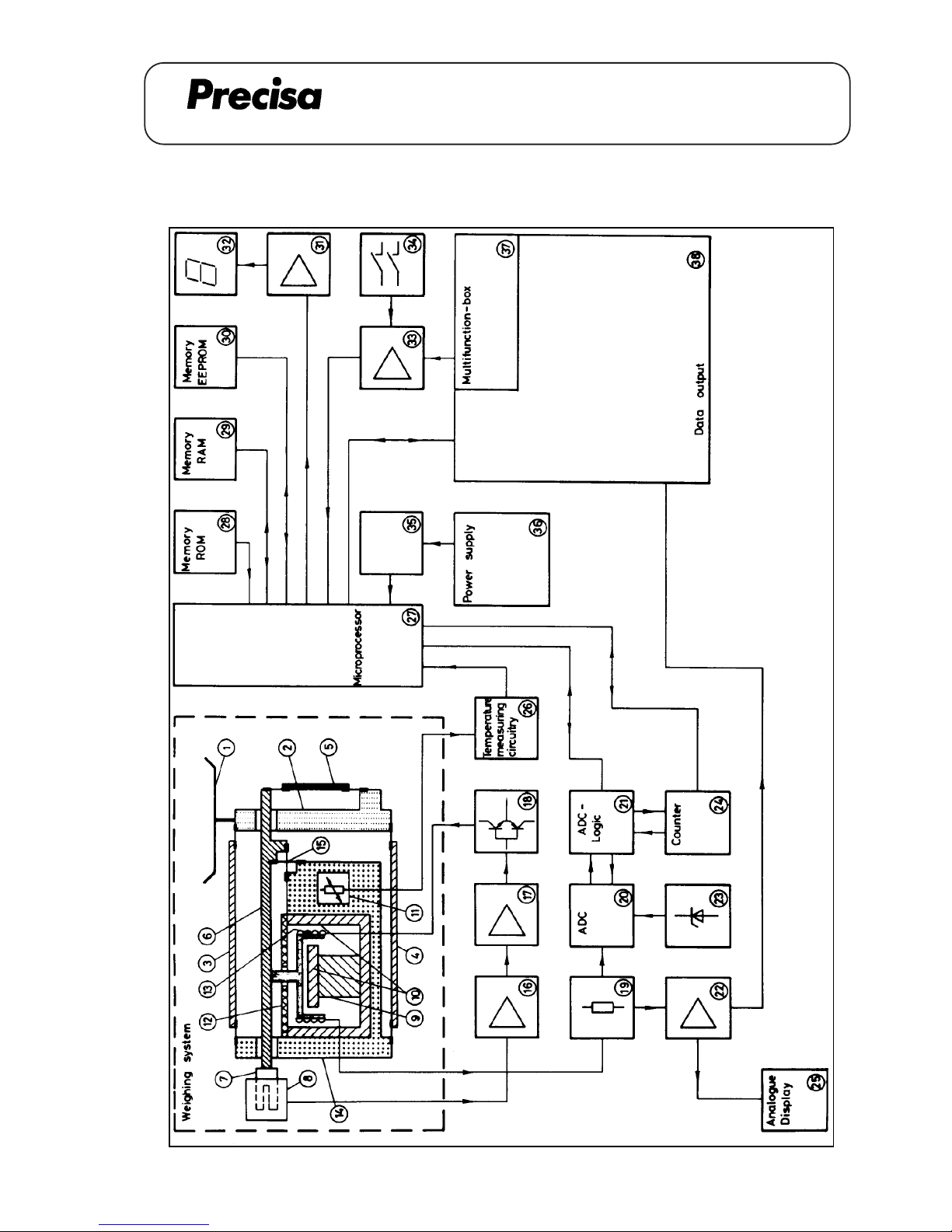
Legend of elementary diagram
1. Weighing pan
2. Support
3. Top flexure arm
4. Bottom flexure arm
5. Flexure strap
6. Balance arm
7. Vane
8. Light detector
9. Permanent magnet
10. Pole piece
11. Temperature compensation (NTC-Resistor)
12. Magnetism screen
13. Compensation coil
14. Chassis
15. Balance arm’s flexure
16. Input amplifier
17. PID-Regulator
18. Power amplifier
19. Measure resistor
20. Analogue-Digital Converter (ADC)
21. ADC-Logic
22. Buffer amplifier
23. Reference voltage source
24. Counter
25. Analogue dispaly
26. Temperature measuring circuitry
27. Microprocessor
28. Programme memory (EPROM)
29. Data memory (RAM)
30. Non-Volatile data memory (EEPROM)
31. Display controller
32. Display
33. Key driver
34. ON/OFF, MODE and T-Key
35. “Power-ON-Reset” Logic
36. Power Supply
37. Multifunctionbox
38. Analogue output
Legende zu Prinzipschaltbild
1. Waagschale
2. Gehänge
3. Lenker oben
4. Lenker unten
5. Koppel
6. Waagbalken
7. Fahne
8. Lichtschranke
9. Magnet
10. Pol
11. Temperaturfühler (NTC-Widerstand)
12. Magnet-Abschirmung
13. Spule
14. Chassis
15. Lager für Waagbalken
16. Eingangsverstärker
17. PID-Regler
18. Endverstärker
19. Messwiderstand
20. Analog-Digital-Wandler
21. Steuerlogik für AD-Wandler
22. Verstärker
23. Referenzspannungsquelle
24. Zähler
25. Analoganzeige
26. Temperaturmesschaltung
27. Microprozessor
28. Programmspeicher (EPROM)
29. Datenspeicher (RAM)
30. Nichtflüchtiger Datenspeicher (EEPROM)
31. Anzeigeansteuerung
32. Digitalanzeige
33. Tastenansteuerung
34. ON/OFF, MODE und T-Taste
35. “Power-ON-Reset” Logik
36. Netzteil
37. Multifunktionenbox (Option)
38. Datenausgänge (Option)
Page 6
PAG OERLIKON AG
SERIES-300 S / SCS
ELEMENTARY DIAGRAM / PRINZIPSCHALTBILD
FUNCTIONAL DESCRIPTIOIN
Weighing System Description
Mechanics
The force caused by any weight which is placed on the weighing pan [1] reaches the support [2] directly. The
support [2] is sustained in a parallel configuration by the top [3] and bottom [4] flexure arms. The support [2]
leads the force through the flexure strap [5] to the balance arm [6] . The arm [6] is connected to the flexures
[15] on the chassis [14] . The balance arm [6] leads the force with a certain reduction ratio to the compensation coil [13] which is located in the center of the magnetic-system.
Magnetic-System
The magnetic system consists of a permanent magnet [9] and the pole piece [10] . They lead the magnetic
field to the compensation coil [13] . The magnetic system, is covered by a screen [12] , to inhibit the break-out
of the stray-field.
Balance arm location
The position of the balance arm [6] is set by the light detector [8] which gets the light through the vane [7].
Measure principle and regulation
Any weight placed on the weighing pan [1] moves the balance arm [6] from its zero-position. The light
detector [8] gives the deviation from the zero-position as an electric signal to the input amplifier [16] and to
the PID-Regulator [17] . The PID-ReguIator [17] changes its output voltage, which goes via the power
amplifier [18] to the compensation coil [13] , till the force change on the coil [13] is sufficient to put the
balance arm [6] back to its initial zero-position. The position of the balance arm [6] , is in the steady-state
now, and the current through the coil [13] is proportional to the weight placed on the weighing pan [1] .
Electronical Evaluation of the Measure Current
The coils’ current is converted to a measure voltage by the measure resistor [19] . This measure voltage
goes on the one side via the buffer-amplifier [22] , to the analogue display [25] , and the analogue output [38]
; on the other side it feeds the analogue to digital converter [20] (AD-Converter) . The AD-Converter [20]
compares the signal with the reference voltage source [23] . The AD-Converter [20] works in the “Dual-SlopeMethod” and is controlled by the microprocessor [27] by means of the AD-Logic [21] . The digital output signal
reaches the microprocessor [27] through the counter [24]. The Reset-Logic [35] supervises the power supply
[36] and enables the microprocessor [27] to run, if there is sufficient supply voltage. The microprocessor [27]
sends the display-data to the display-controller [31] , where the data is latched and displayed by the dispIay
[32] .
The keys “ON/OFF”, "MODE" and “T” [34] give information through the driver [33] to the microprocessor . If
the balance is switched off by the “ON/OFF”-key, it remains in the “standby” mode, that means the balance is
ready to work with no warm-up time after switching on again.
A 01.03
Page 7
PAG OERLIKON AG
SERIES-300 S / SCS
ELEMENTARY DIAGRAM / PRINZIPSCHALTBILD
Microprocessor System
The microprocessor system consists of the following parts:
Programme [28] : Command memory of the microprocessor [27] . It contains the program-
me instructions in a “Read Only Memory” (ROM).
Data memory [29] : Data memory of the microprocessor . This memory is used to store and
read the data. After a mains failure the data is not available anymore. It is
a “Static Random Access Memory” (RAM).
Non-Volatile data memory [30] : This memory is used to store the important data that has to be available
after a mains failure (e.g. Linearity data, calibration data, temperature
adjustment data). It contains an “Electronically Erasable Programmable
Read Only Memory” (EEPROM).
The following tasks are done by the Microprocessor :
- Read and evaluated the data of the A-D Converter
- Optimize the integration time stability detection
- Measure the temperature of the weighing system
- Compensation of the temperature drift on the zero point
- Compensation of the temperature drift on the sensitivity
- Correction of non-linearity
- Calibration to a reference weight
- Drive the data-output
- Execute the multifunctionbox commands (e.g. piece-counting)
- Read the “T”, "MODE" and “ON/OFF”-keys
A 01.04
Page 8
PAG OERLIKON AG
SERIES-300 S / SCS
ELEMENTARY DIAGRAM / PRINZIPSCHALTBILD
A 01.05
FUNKTIONSBESCHREIBUNG
Beschreibung der Wägezelle
Mechanik
Durch Auflegen eines Gewichtes auf die Waagschale [1] gelangt die zu messende Kraft auf das Gehänge [2].
Dieses Gehänge [2] wird durch die oberen Lenker [3] und die unteren Lenker [4] geführt. Die Kraft wird nun
über eine Koppel [5] auf den Waagbalken [6] geleitet Der Waagbalken [6] ist am Lager [15] am Chassis [14]
aufgehängt. Mit entsprechender Untersetzung leitet der Waagbalken [6] die Kraft auf die Spule [13] , die sich
im Magnetsystem befindet.
Magnetsystem
Das Magnetsystem besteht aus dem Magneten [9] und den beiden Polen [10] , die das Magnetfeld zur Spule
leiten. Um das Austreten des Streufeldes nach oben zu verhindern, ist das Magnetsystem durch die Abschirmung [12] abgedeckt.
Abtastung des Waagbalkens
Die Position des Waagbalkens [6] wird mit der Fahne [7] der Lichtschranke [8] zugeführt und dort optisch
abgetastet.
Messprinzip und Regelkreis
Wird ein Gewicht auf die Waagschale [1] gelegt, so bewegt sich der Waagbalken [6] aus seiner Null-Lage.
Die Lichtschranke [8] gibt nun diese Abweichung von der Null-Lage als elektrisches Signal an den Eingangsverstärker [16] und weiter zum PID-Regler [17] . Dieser PID-Regler [17] ändert nun seine Ausgangsspannung, die über den Endverstärker [18] die Spule [13] speist, bis die Kraftänderung auf die Spule [13] ausreicht, um den Waagbalken [6] in seine Null-Lage zurückzudrücken. Somit ist die Lage des Waagbalkens [6]
in eingeschwungenem Zustand immer gleich und der Strom durch die Spule [13] ist proportional dem aufgelegten Gewicht auf der Waagschale [1] .
Elektronische Auswertung des Messtroms
Mit dem Messwiderstand [19] wird der Spulenstrom in die Messpannung umgewandelt. Die Messpannung
gelangt nun einerseits über den Entkopplungsverstärker [22] zur Analoganzeige [25] und zum Analogausgang [38] , andererseits wird das Signal dem Analog-Digital- Wandler [20] zugeführt. Im Analog-DigitalWandler [20] wird das Signal mit der Referenzspannungsquelle [23] verglichen. Der AD-Wandler arbeitet
nach dem “Dual-Slope-Verfahren”. Der AD-Wandler wird mit Hilfe der Ansteuerlogik [21] vom Microprozessor
[27] angesteuert. Der digitale Ausgang gelangt von der Steuerlogik [21] über den Zähler [24] zum Microprozessor [27] . Die Reset-Logik [35] über wacht die Spannung des Netzteiles [36] und gibt den Microprozessor
[27] bei genügender Speisespannung zum Arbeiten frei. Die anzuzeigenden Daten gelangen vom Microprozessor [27] zur Anzeigeansteuereinheit [31] , wo sie gespeichert und über das Display [32] angezeigt werden.
Die Tasten [34] “T”, "MODE" und “ON/OFF” geben die Information über den Treiber [33] an den
Microprozessor [27] . Wird die Waage über die Taste “ON/OFF” ausgeschaltet, so bleibt sie im “Stand by”
Betrieb, d.h. die Waage kann jederzeit wieder betriebswarm eingeschaltet werden.
Page 9
PAG OERLIKON AG
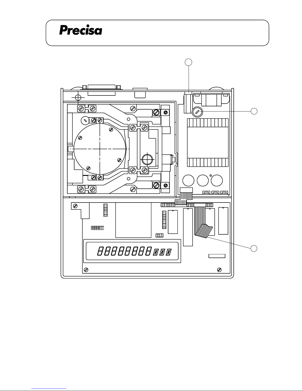
2
1
3
Key No. Description Beschreibung
1 Mains voltage swich Drehschalter Netzspannung
2 Fuse Sicherung
3 Flat wire Flachbandkabel
SERIES-300 S / SCS
A 02.01
OPENING A BALANCE /
CHANGING OF MAINS VOLTAGE
ÖFFNEN EINER WAAGE /
SPANNUNGSUMSCHALTUNG
Page 10
PAG OERLIKON AG
General procedure for opening a balance
1. Disconnect the balance from the mains (pull out the mains plug)
2. Remove the weighing pan and the pan holder
3. Remove the retention ring and if mounted the cover panel
4. Remove the windshield if mounted
5. Remove the dust cover
6. Loose the screw on the balance top with a screwdriver no.4
7. Lift the balance top
8. Disconnect the flat wire (3)
Procedure for changing the mains voltage (300S)
1.-8. See "General instructions to open a balance"
9. Turn the switch (1) into the desited position with a screwdriver no.3
10. Change or check the fuse (2)
fuse type for 110V ---> T 160 mA
fuse type for 220V ---> T 80 mA
11. Connect the flat wire (3) , reassemble the balance
Allgemeine Vorgehensweise beim Oeffnen einer Waage
1. Waage vom Netz trennen (Netzstecker ziehen)
2. Waagschale und Schalenträger entfernen
3. Haltering und evtl. Deckblech entfernen
4. evtl. Windschutz entfernen
5. Staubschutz entfernen
6. Zylinderschraube am Waagenoberteil mit einem Schraubenzieher Nr.4 lösen
7. Waagenoberteil abheben
8. Flachbandkabel (3) lösen
Vorgehensweise bei einer Spannungsumschaltung (300S)
1.-8. Siehe "Allgemeine Vorgehensweise beim Oeffnen einer Waage"
9. Drehschalter (1) mit Schraubenzieher Nr.3 auf die gewünschte Netzspannung drehen
10. Sicherung (2) auswechseln bzw. kontrollieren:
Sicherungstyp für 110V ----> T 160 mA
Sicherungstyp für 220V ----> T 80 mA
11. Flachbandkabel (3) anschliessen, Waage wieder zusammensetzen
SERIES-300 S / SCS
A 02.02
OPENING A BALANCE /
CHANGING OF MAINS VOLTAGE
ÖFFNEN EINER WAAGE /
SPANNUNGSUMSCHALTUNG
Page 11
PAG OERLIKON AG
SERIES-300 SIP
OPENING A BALANCE
ÖFFNEN EINER WAAGE
General procedure for opening a balance IP65
1. Disconnect the balance from the mains (pull out the mains plug)
2. Remove the weighing pan, lift carefully the pan holder
3. Dismantle the retention ring, take off the cover plate
4. Loose the 4 screws of the cover, take off the cover
5. Spread the locking ring and remove it
6. Take off the membrane
7. Dismantle the dust-cover, loose the screw of the housing's top
8. Lift the housing's top a bit, disconnect the flat-wire
9. Take off the housing's top
Mounting the housing's top IP65
1. Connect the flat-wire to the housing's top
2. Mount carefully the housing's top on the balance, fasten the screw on the housing's top
3. Pull the dust-cover over the balance
4. Insert the membrane, mount the locking ring
5. Align the membrane (without any stress and waves)
6. Place carefully the cover (do not move it sidewards), fasten it with 4 screws
7. Mount the cover plate and the retention ring
8. Bring carefully the pan holder in place, mount the weighing pan
Allgemeine Vorgehensweise beim Oeffnen einer Waage IP65
1. Waage vom Netz trennen (Netzstecker ziehen)
2. Waagschale abnehmen, Waagschalenträger vorsichtig herausziehen
3. Haltering demontieren, Deckblech abnehmen
4. 4 Befestigungsschrauben der Abdeckung lösen, Abdeckung entfernen
5. Klemmring leicht spreizen und abheben
6. Membrane entfernen
7. Schutzhaube abheben, Sechskantschraube am Gehäuseoberteil lösen
8. Gehäuseoberteil leicht anheben, Flachbandkabel lösen
9. Gehäuseoberteil ganz entfernen
Montage Gehäuseoberteil IP65
1. Flachbandkabel am Gehäuseoberteil anschliessen
2. Gehäuseoberteil sauber auf der Waage positionieren, Sechskantschraube anziehen
3. Staubschutzhülle über die Waage legen
4. Membrane einlegen, Klemmring montieren
5. Membrane ausrichten (spannungsfrei, ohne Wellen)
6. Abdeckung vorsichtig aufsetzen (seitlich nicht verschieben), 4 Befestigungsschrauben anziehen
7. Deckblech montieren, Haltering montieren
8. Waagschalenträger vorsichtig einfahren, Waagschale aufsetzen
A 02.03
Page 12
PAG OERLIKON AG
SERIES-300 S / SCS
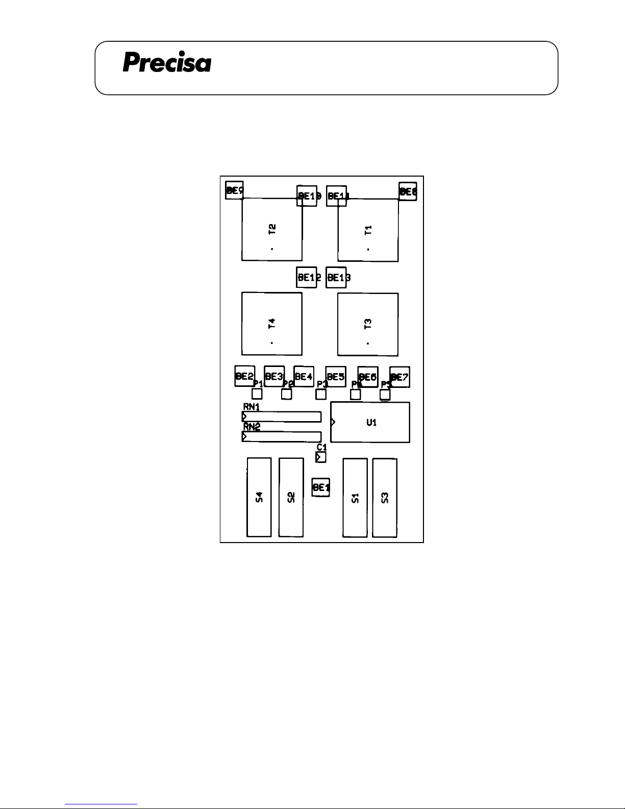
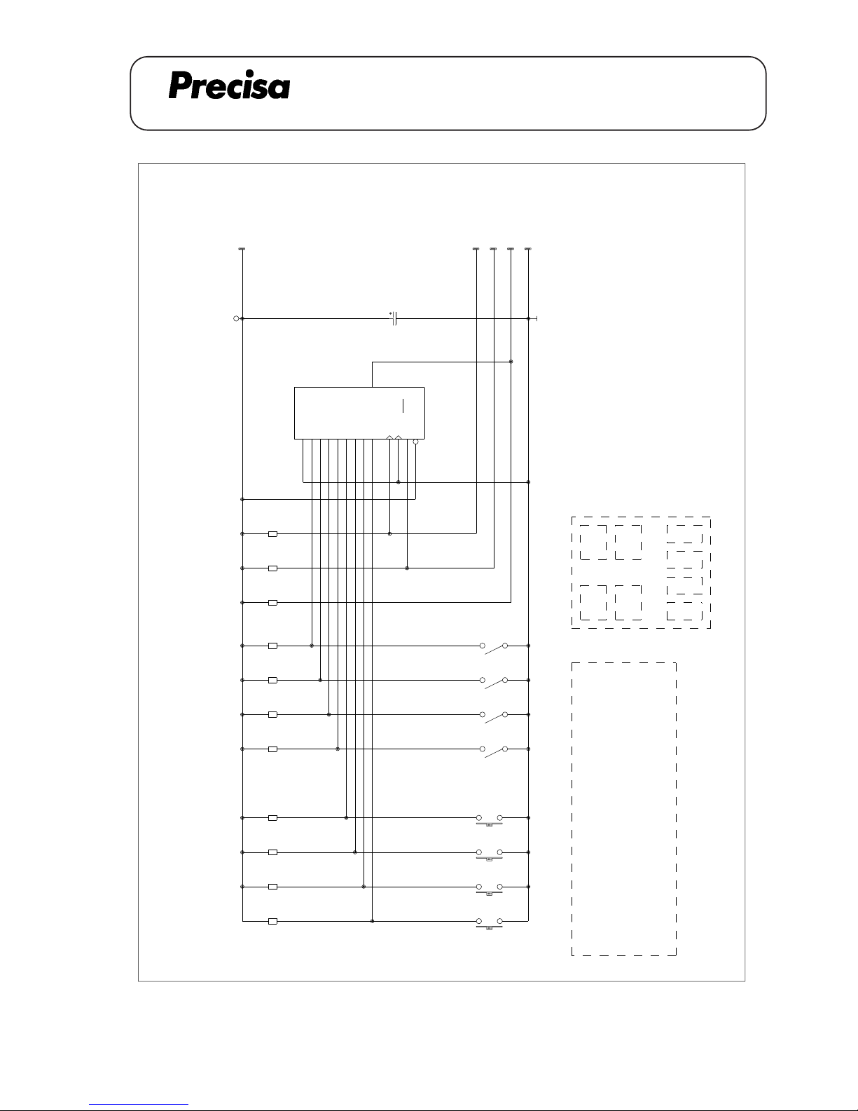
MULTIFUNCTIONBOX BOARD 350-7213-010
MULTIFUNCTIONBOX BOARD 350-7213-010
A 03.01
Pos. No. Order No. Description Type
C1 3438-610 CAPACITOR 10 uF
RN1, RN2 3360-004 RESISTOR 10 K-RN 8
S1, S2, S3, S4 3603-008 MICROSWITCH
T1, T2, T3, T4 3602-007 KEY
Page 13
PAG OERLIKON AG
SERIES-300 S / SCS
MULTIFUNCTIONBOX BOARD 350-7213-010
A 03.02
1
5
RN2D
1
2
RN1A
10k
1
3
RN1B
1
4
RN1C
1
5
RN1D
1
6
RN1E
1
7
RN1F
1
8
RN1G
1
2
RN2A
1
3
RN2B
1
4
RN2C
VCC
+5V
P1
SER
1A 2B 3C 4D 5E 10F 11G 12H 14
CLK
7
INH
6
SH/L
D
15
CLR
9
QH
13
IC1
74HC166
C1
10uF
P2
P3
P4
CLKPEDATA
S4
S
S1
S
S2
S
S3
S
T3
T
T4
T
T1
T
T2
T
PRINT DIN STECKER 8-POL
GND
GND
P5
T2
T4
T1
T3613
45
78
2PIN 1
PIN 2
PIN 3
PIN 4
PIN 5
PIN 6
PIN 7NC
<->
<->
<->
<->
<->
CODIERUNG
P2
P1P5P3
P4
PIN 8NC S3 S1 S2 S4
3507213.SCH 061288
Page 14
PAG OERLIKON AG
SERIES-300 S
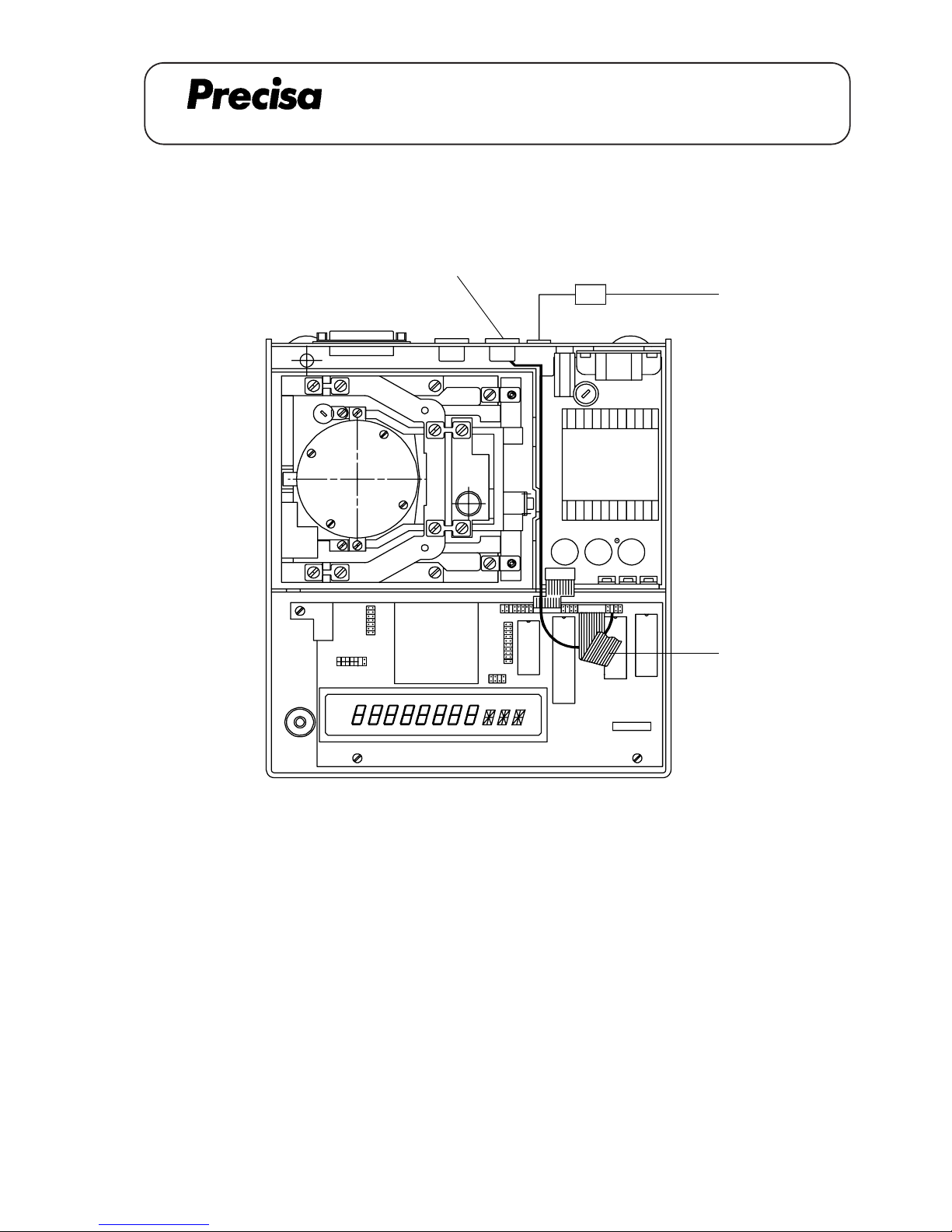
CONNECTING CABLE external T-key (350-8313)
CONNECTING CABLE external T-key 350-8313
Key No. Part No. Description
1 350-8313 Cable
2 PN 1100-011 Screw M3x6
3 350-4033-003 Label
ex-T
[3]
[A]
[1,2]
A 04.01
Page 15
PAG OERLIKON AG
SERIES-300 S
CONNECTING CABLE external T-key (350-8313)
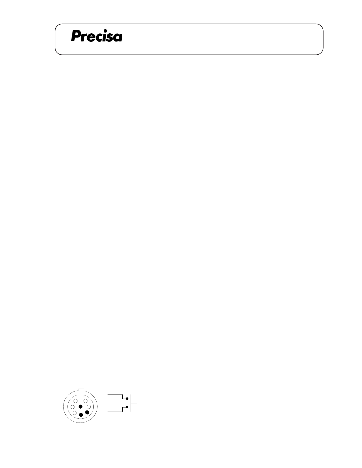
Installation instruction for connecting cable (external T-key)
1. Lift the balance top, disconnect the flat wire [A] and remove the coverplate from the data output
opening in the rear of the balance.
2. Lead the cable [1] through the opening and fix the analogue output plug with two screws [2].
3. Lead the cable [1] through the cable channel between the transformer and the partition wall and plug it to
the pin-type socket.
4. Reassemble balance, connect the flat wire [A] and mount the label [3].
-> Part-No. for external T-key: 350-8904
Einbauanleitung für Verbindungskabel (externe T-Taste)
1. Waagenoberteil abheben, Flachbandkabel [A] lösen und Datenausgang-Abdeckung auf der Rückseite
der Waage entfernen.
2. Kabel [1] durch die Öffnung führen und Stecker mit zwei Schrauben [2] festschrauben.
3. Kabel [1] durch den Kabelkanal zwischen Trafo und Gehäuse-Trennwand durchführen und auf Stiftleiste
stecken.
4. Waage wieder zusammensetzen, Flachbandkabel [A] anschliessen und Schild [3] montieren.
-> Bestellnummer für externe T-Taste: 350-8904
Notice d’installation pour Ie câble de jonction (touche-T externe)
1. Soulever la partie supérieure de la balance, débrancher le câble plat [A] et retirer le couvercle de la sortie
de données en arrière de la balance.
2. Passer le câble [1] à travers de l’ouverture et fixer Ia fiche avec deux vis [2].
3. Passer le câble [1] à travers du caniveau électrique entre le transformateur et la cloison de séparation du
boîtier et le relier avec le culot à ergots.
4. Remonter la balance, connecter de nouveau le câble plat [A] et monter l'étiquette [3].
-> Numéro de commande pour la touche T externe: 350-8904
Tare
4
6
2
2
6
4 Code
A 04.02
Page 16
PAG OERLIKON AG
SERIES-300 S
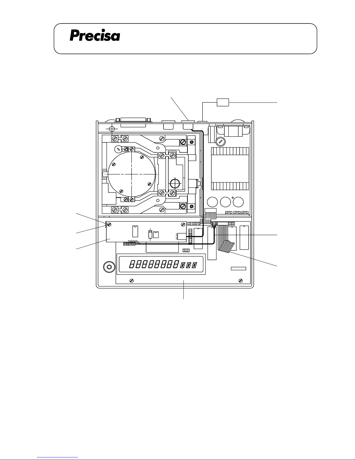
DATA OUTPUT 20mA current loop (350-8803)
DATA OUTPUT 20mA current loop, bi-directional 350-8803
CL
[5]
[1,2]
[C]
[D]
[A]
[4]
[B]
[3]
Key No. Part No. Description
1 350-7027 Cable
2 PN 1100-011 Screw M3x6
3 350-7211-010 Data output board
4 PN 1048-009 Distance holder M3x20
5 350-4033-001 Label
A 05.01
Page 17
PAG OERLIKON AG
SERIES-300 S
DATA OUTPUT 20mA current loop (350-8803)
Istallation instruction for data output (20mA current loop)
1. Lift the balance top, disconnect the flat wire [D] and remove the coverplate from the data output opening in
the rear of the balance.
2. Lead the cable [1] through the opening and fix the data output plug with two screws [2]. Lead the cable [1]
through the cable channel between the transformer and the partion wall and plug it to the data output board
[3].
3. Fix the data output board [3] with two distance holders [4] on the main board [A] (with two screws [B]
from the main board). Connect the data output cable [C] on the main board [A].
4. Reassemble balance, connect the flat wire [D] and mount the label [5].
For further informations about type of data transmission and remote control commands see chapter 11.
Einbauanleitung für Datenausgang (20mA current loop)
1. Waagenoberteil abheben, Flachbandkabel [D] lösen und Datenausgang-Abdeckung auf Rückseite der
Waage entfernen.
2. Kabel [1] durch Öffnung führen und Stecker mit zwei Schrauben [2] festschrauben. Kabel [1] durch
den Kabelkanal zwischen Trafo und Gehäuse-Trennwand durchführen und mit Datenausgangsprint [3]
verbinden.
3. Datenausgangsprint [3] mit zwei Distanzhaltern [4] auf dem Hauptprint [A] befestigen (mit Schrauben
[B] vom Hauptprint). Datenausgangs-Kabel [C] mit Hauptprint [A] verbinden.
4. Waage wieder zusammensetzen, Flachbandkabel [D] anschliessen und Schild [5] montieren.
Für weitere Informationen über Art der Datenübertragung und über Fernsteuerbefehle siehe Kapitel 11.
Notice d’installation pour la sortie de données (boucle de courant 20mA)
1. Soulever la partie supérieure de la balance, débrancher le câble plat [D] et retirer le couvercle de la sortie
de données en arrière de la balance.
2. Passer le câble [1] à travers de l’ouverture et fixer la fiche avec deux vis [2]. Passer le câble [1] à
travers du caniveau électrique entre le transformateur et la cloison de séparation du boîtier et le relier avec
la carte de la sortie de données [3].
3. Fixer la carte de la sortie de données [3] avec deux ports de distance [4] sur la carte principale [A]
(avec deux vis [B] de la carte principale). Relier le câble [C] de la sortie de données avec la carte
principale [A].
4. Remonter à nouveau la balance, connecter le câble plat [D] et monter l'étiquette [5].
Plus d'informations du type de transfert de donées et des ordres de commande à distance voire chapitre 11.
A 05.02
Page 18
PAG OERLIKON AG
SERIES-300 S
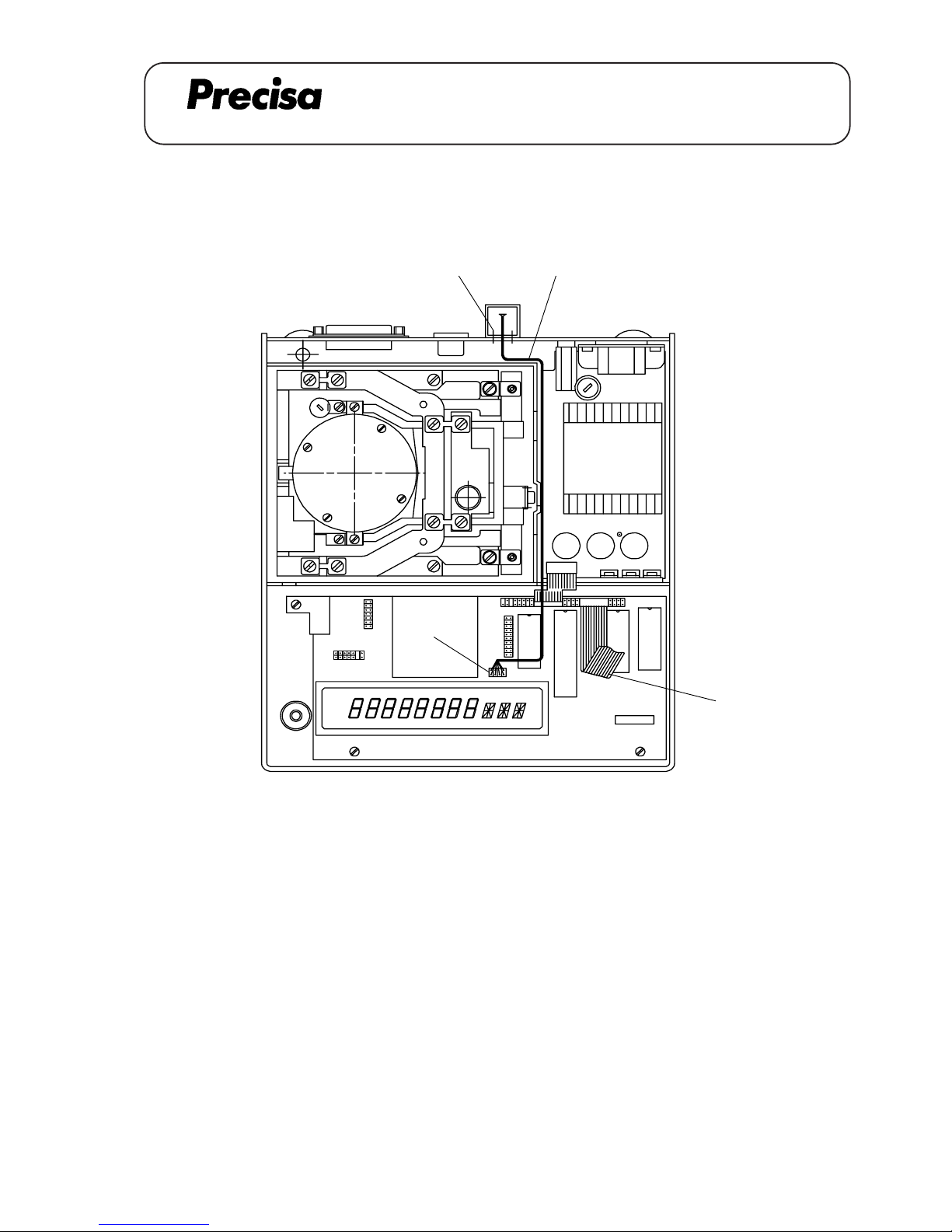
REMOTE DISPLAY mounted to the balance (350-8830)
REMOTE DISPLAY mounted to the balance 350-8830
Key No. Part No. Description
1 350-8830 Remote display
2 PN 1100-058 Screw M3x10
[B]
[2] [1]
[A]
A 06.01
Page 19
PAG OERLIKON AG
SERIES-300 S
REMOTE DISPLAY mounted to the balance (350-8830)
Installation instruction for remote dispIay (mounted to the balance)
1. Lift the balance top, disconnect the flat wire [A] and remove the coverplate (small) from the data output
opening in the rear of the balance.
2. Lead the cable [1] through the opening and fix the display support with two screws [2]. Lead the cable [1]
through the cable channel between the transformer and the partition wall and connect it to the plug [B] on
top of the display tube.
3. Reassemble balance and connect the flat wire [A].
Einbauanleitung für Fernanzeige (am Gerät montiert)
1. Waagenoberteil abheben, Flachbandkabel [A] lösen und Datenausgang-Abdeckung (klein) auf der Rückseite der Waage entfernen.
2. Kabel [1] durch Öffnung führen und Fernanzeige-Stütze mit zwei Schrauben [2] festschrauben. Kabel
[1] durch den Kabelkanal zwischen Trafo und Gehäuse-Trennwand durchführen und oberhalb der Anzeigeröhre an Stecker [B] anschliessen.
3. Waage wieder zusammensetzen und Flachbandkabel [A] anschliessen.
Notice d’instaIIation pour I’affichage à distance (fixé à la balance)
1. Soulever la partie supérieure de la balance, débrancher le câble plat [A] et retirer le couvercle de la sortie
de données (petit) en arrière de la balance.
2. Passer le câble [1] à travers de l’ouverture et fixer le support avec deux vis [2]. Passer le câble [1] à
travers du caniveau électrique entre le transformateur et la paroi de séparation du boîtier et le brancher à la
fiche [B].
3. Remonter la balance et connecter de nouveau le câble plat [A].
A 06.02
Page 20
PAG OERLIKON AG
SERIES-300 S
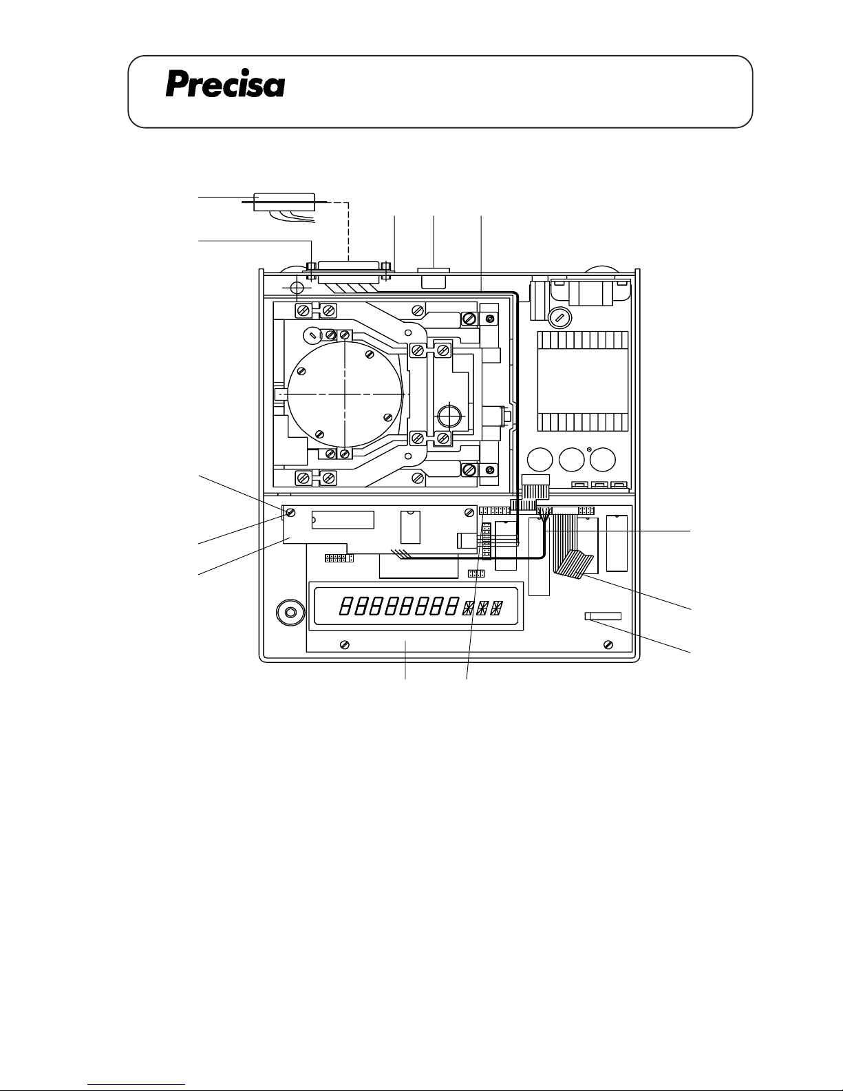
DATA OUTPUT IEC 625 / IEEE 488 (350-8833 / 8834)
A 07.01
IEC 625
Key No. Part No. Description
1 350-7028 Cable
2 350-3004 Special screw
PN 1300-003 Nut
PN 1500-030 Washer
PN 1500-034 Spring washer
3 350-7210-010 Data output board
4 PN 1048-009 Distance holder M3x20
5 350-4015 Cover
DATA OUTPUT IEC 625 / IEEE 488 350-8833 / 8834
[C] [F]
[G]
[2]
[3]
[B]
[4]
[D]
[E]
[5]
[A]
[1]
IEEE 488
Key No. Part No. Description
1 350-7023 Cable
2 350-3015 Special screw
PN 1300-003 Nut
PN 1500-030 Washer
PN 1500-034 Spring washer
3 350-7210-010 Data output board
4 PM 1048-009 Distance holder M3x20
[H]
1
Page 21
PAG OERLIKON AG
SERIES-300 S
DATA OUTPUT IEC 625 / IEEE 488 (350-8833 / 8834)
A 07.02
Assembly instruction for the data output IEC 625 / IEEE 488
1. Lift the balance top and disconnect the flat wire [E].
2. Dismantle the jack [A] and pull it out a little bit. Unplug the plug [F].
3. Dismantle the data output RS 232 [G].
4. Fix the cover [5] on the plug (only IEC 625). Lead the cable [1] through the opening and fix the plug with
two screws [2]. Secure it with the nut, the washer and the spring washer.
5. Lead the cable [1] through the cable channel between the transformer and the partition wall and connect
it to the data output board [3].
6. Fix the data output board [3] with two distance holders [4] on the main board [C] (with two screws [B]
from the main board). Bring the cable [1] according to the drawing on page 1 in place (do not jam any
wires).
7. Connect the cable [D] and fix the jack [A].
8. Switch the DIL-Switch [H] no.1 to the position ON.
9. Reassemble the balance and connect the flat wire [E].
Einbauanleitung für IEC 625 / IEEE 488
1. Waagenoberteil abheben und Flachbandkabel [E] lösen.
2. Buchse [A] demontieren und etwas herausziehen. Stecker [F] ziehen.
3. Datenausgang RS 232 [G] demontieren.
4. Abdeckung [5] auf die Steckerbuchse klemmen (nur IEC 625). Kabel [1] durch die Öffnung führen
und den Stecker mit zwei Schrauben [2] festschrauben. Mit 6-kt Mutter, U-Scheibe und Federring
sichern.
5. Kabel [1] durch den Kabelkanal zwischen Trafo und Gehäuse-Trennwand durchführen und mit dem
Print [3] verbinden.
6. Print [3] mit zwei Distanzhaltern [4] auf den Hauptprint [C] schrauben (mit Schrauben [B] vom
Hauptprint). Kabel [1] genau nach Zeichnung Seite 1 verlegen (keine Litzen einklemmen).
7. Kabel [D] anschliessen und Buchse [A] wieder befestigen.
8. DIL-Switch [H] Nr.1 auf Position ON stellen.
9. Waage wieder zusammensetzen und Flachbandkabel [E] anschliessen.
Page 22
PAG OERLIKON AG
SERIES-300 S
DATA OUTPUT IEC 625 / IEEE 488 (350-8833 / 8834)
A 07.03
Notice d'installation pour la sortie de donées IEC 625 / IEEE 488
1. Soulever la partie supérieure de la balance et débrancher le câble plat [E].
2. Démonter la douille [A] et la retirer un peu. Retirer la fiche [F].
3. Démonter la sortie de donées RS 232 [G].
4. Serrer le couvercle [5] sur la fiche (seulement IEC 625). Passer le câble [1] à travers de l'ouverture et
fixer la fiche avec deux vis [2]. Les arrêter avec l'ecrou, la rondelle et la rondelle ressort.
5. Passer la câble [1] à travers du caniveau électrique entre le transformateur et la paroi de séparation du
boîtier et le connecter avec la carte de sortie de donées [3].
6. Fixer la carte de sortie de donées [3] avec deux ports de distance [4] sur la carte principale [C] (avec
deux vis [B] de la carte principale. Insérer le câble [1] selon le dessin page 1 (ne coincer pas des
cordons).
7. Connecter le câble [D] et remonter la douille [A].
8. Mener le DIL-Switch [H] no.1 à la position ON.
9. Remonter la balance et connecter de nouveau le câble plat [E].
Page 23
PAG OERLIKON AG
SERIES-300 S
DATA OUTPUT IEC 625 / IEEE 488 (350-8833 / 8834)
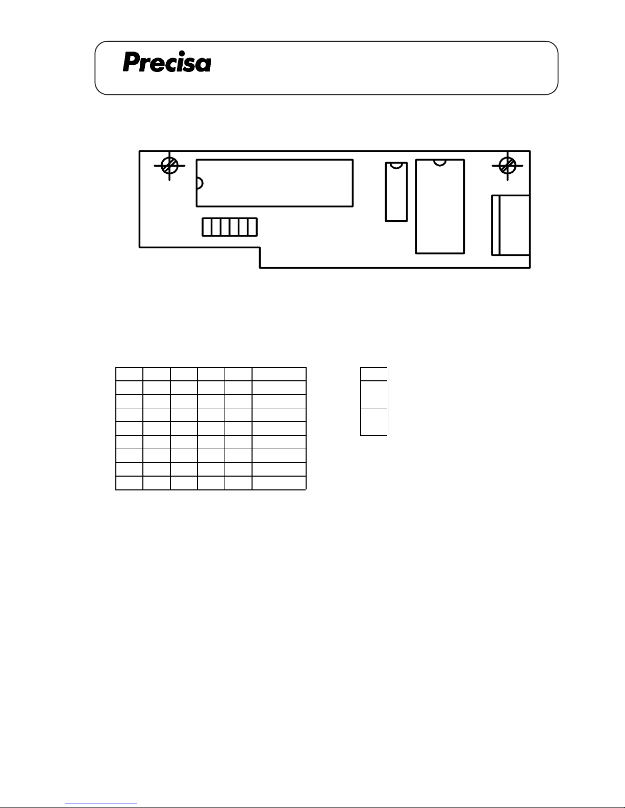
Switch settings (on = 1)
Address switch Capital switch
12345Address 6
00000 0 Capital / small letters
10000 1 0 off : g dwt ozt KT pcs
01000 2 Capital letters
11000 3 1 on :GDWTOZTKTPCS
00100 4
01111 30
11111 31
1
2
45
6 3
A 07.04
Page 24
PAG OERLIKON AG
SERIES-300 S
DATA OUTPUT IEC 625 / IEEE 488 (350-8833 / 8834)
Datatransfer sequence (total 16 characters in 7 bit-ASCII-code)
Blanks transmitted, if : - leading zeroes
- no decimal point
- no units (instability is greater than the selected stability)
Examples for datatransfer
12345678910111213141516
+ 1247,68 g + 1 2 4 7 . 6 8 g CR LF
+ 802,28 dwt + 8 0 2 . 2 8 d w t CR LF
+ 4,011 ozt + 4 . 0 1 1 o z t CR LF
+ 48216 pcs + 4 8 2 1 6 p c s CR LF
Over Load OL
Under Load UL
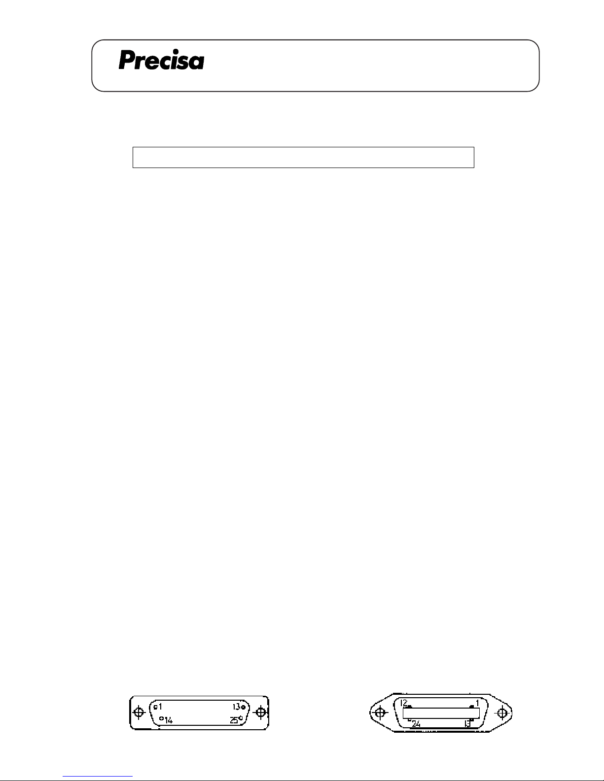
IEC 625
Contact Signal Contact Signal
1 DIO 1 14 DIO 5
2 DIO 2 15 DIO 6
3 DIO 3 16 DIO 7
4 DIO 4 17 DIO 8
5 REN 18 GND (5)
6 EOI 19 GND (6)
7 DAV 20 GND (7)
8 NRFD 21 GND (8)
9 NDAC 22 GND (9)
10 IFC 23 GND
(10)
11 SRQ 24 GND (11)
12 ATN 25 GND (12)
13 shield
IEEE 488
Contact Signal Contact Signal
1 DIO 1 14 DIO 6
2 DIO 2 15 DIO 7
3 DIO 3 16 DIO 8
4 DIO 4 17 REN
5 EOI 18 GND
6 DAV 19 GND
7 NRFD 20 GND
8 NDAC 21/ GND
9 IFC 22 GND
10 SRQ 23 GND
11 ATN 24 GND
12 shield
13 DIO 5
S D6D5DPD4D3D2D1D0B B U U U CFLF
1 2 3 4 5 6 7 8 9 10 11 12 13 14 15 16
B = Blank
S = Sign (+ or - or blank)
DP = Decimal Point (can be anywhere between D0 and D6)
U = Unit
CR = Carriage Return
LF = Line Feed with EOI
A 07.05
Page 25
PAG OERLIKON AG
SERIES-300 S
CONNECTING CABLE
Remote display, freestanding / wall mounted (350-8836)
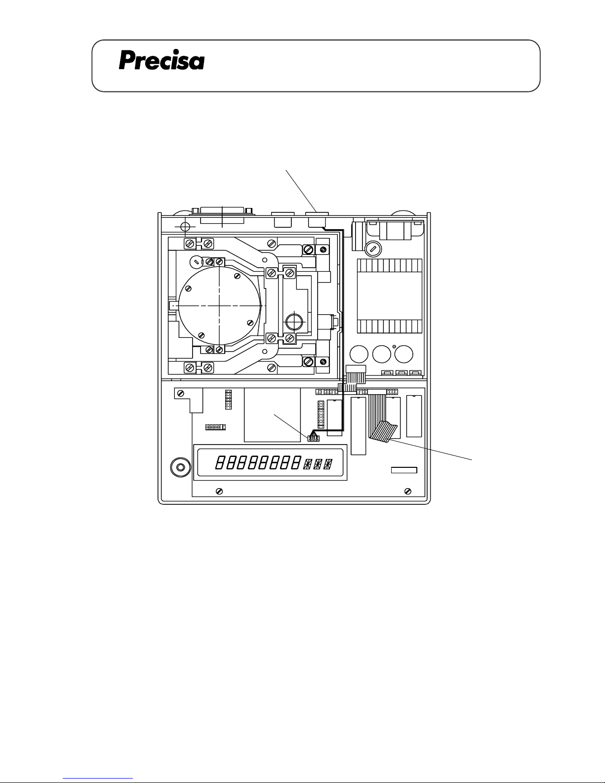
CONNECTING CABLE remote display, freestanding / wall mounted 350-8836
[1,2]
[A]
[B]
Key No. Part No. Description
1 350-8836 Cable
2 PN 1100-011 Screw M3x6
A 08.01
Page 26
PAG OERLIKON AG
SERIES-300 S
CONNECTING CABLE
Remote display, freestanding / wall mounted (350-8836)
Einbauanleitung für Verbindungskabel 350-8836 (Tischmodell von Fernanzeige)
1. Waagenoberteil abheben, Flachbandkabel [A] lösen und Datenausgang-Abdeckung (klein) auf der
Rückseite der Waage entfernen.
2. Kabel [1] durch Öffnung führen und Buchse mit zwei Schrauben [2] festschrauben. Kabel [1] durch
den Kabelkanal zwischen Trafo und Gehäuse-Trennwand durchführen und oberhalb der Anzeigeröhre an
Stecker [B] anschliessen.
3. Waage wieder zusammensetzen, Flachbandkabel [A] anschliessen.
-> Bestellnummer für Fernanzeige (freistehend): 350-8873
Installation instruction for connecting cable (Remote display, freestanding)
1. Lift the balance top,disconnect the flat wire [A] and remove coverplate (small) from the data output
opening in the rear of the balance.
2. Lead the cable [1] through the opening and fix the jack with two screws [2]. Lead the cable [1] through
the cable channel between transformer and partition wall and connect it to the plug [B] on top of the
display tube.
3. Reassemble the balance and connect the flat wire [A].
-> Part-No. for remote display (freestanding): 350-8873
Notice d’instaIIatIon pour le câble de jonction (modèle de tabIe de l'affichage à distance)
1. Soulever la partie supérieure de la balance, débrancher le câble plat [A] et retirer le couvercle de la sortie
de données (petit) en arrière de la balance.
2. Passer le câble [1] à travers de l’ouverture et fixer la douille avec deux vis [2]. Passer le câble [1] à
travers du caniveau électrique entre le transformateur et la paroi de séparation du boîtier et le brancher à
la fiche [B].
3. Remonter la balance et connecter le câble plat [A].
-> Numéro de commande pour l'affichage à distance (modèle de table): 350-8873
A 08.02
Page 27
SERIES-300 S
PAG OERLIKON AG
DATA OUTPUT 4-CHANNEL MULTIPLEXER (350-8852)
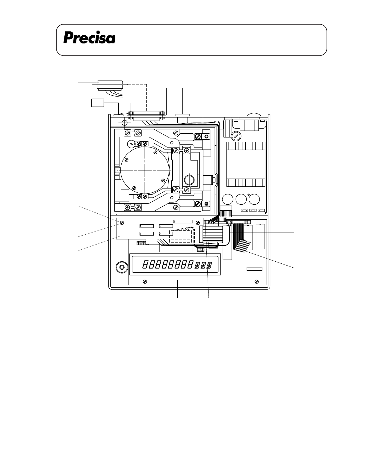
Data output 4-channel multiplexer 350-8852
Key No. Part No. Description
1 350-4015 Cover
2 350-7110 Connecting cable
3 350-7228-010 Multiplexer-board
4 PN 1048-009 Distance holder M3x20
5 350-4047-001 Label for Multiplexer-output
6 350-3014 Special screw
PN 1300-003 Nut
PN 1500-030 Washer
PN 1500-034 Spring washer
[D]
[5]
[6]
[F]
[A]
[1] [B] [2]
[4]
[E]
[3]
[G] [C]
Multi-P
A 09.01
Page 28
SERIES-300 S
PAG OERLIKON AG
DATA OUTPUT 4-CHANNEL MULTIPLEXER (350-8852)
Montage-Anleitung für 4-Kanal Multiplexer
1. Waagenoberteil abheben und Flachbandkabel [A] lösen.
2. Buchse [B] demontieren und etwas herausziehen. Stecker [C] ziehen.
3. Datenausgang RS 232 [D] demontieren, 3 Litzen abklemmen (bleiben in der Waage).
4. Abdeckung [1] auf den Multiplexer-Stecker klemmen, Kabel [2] durch die Öffnung führen und den
Stecker mit zwei Schrauben [6] festschrauben. Mit 6-kt Mutter, U-Scheibe und Federscheibe
sichern.
5. Kabelkanal [7] montieren. Kabel [2] durch den Kabelkanal [7] durchführen und mit dem
Multiplexer-Print [3] verbinden. Klipp [7] 90° abbiegen.
6. Multiplexer-Print [3] mit zwei Distanzhaltern [4] auf den Hauptprint [G] schrauben (mit den
Schrauben [E] vom Hauptprint). Kabel [2] genau nach Zeichnung Seite 1 verlegen (keine Litzen
einklemmen).
7. Kabel [F] anschliessen und Buchse [B] wieder befestigen.
8. Waage wieder zusammensetzen und Flachbandkabel [A] anschliessen.
9. Schild für Multiplexer-Ausgang [5] auf die Gehäuse-Rückwand kleben.
Assembly instructions for the 4-channel multiplexer
1. Lift the balance top and disconnect the flat wire [A].
2. Dismantle the jack [B] and pull it out a little bit. Unplug the plug [C].
3. Dismantle the data output RS 232 [D].
4. Fix the cover [1] on the multiplexer plug, lead the cable [2] through the opening and fix the plug with two
screws [6]. Secure it with the nut, the washer and the spring washer.
5. Lead the cable [2] through the cable channel between the transformer and partition wall and plug it to the
multiplexer board [3].
6. Fix the multiplexer board [3] with two distance holders [4] on the main board [G] (with two screws [E]
from the main board). Bring the cable [2] according to the drawing on page 1 in place (do not jam any
wires).
7. Connect the cable [F] and fix the jack [B].
8. Reassemble the balance and connect the flat wire [A].
9. Stick the label for the multiplexer output [5] on the backside of the housing.
A 09.02
Page 29
SERIES-300 S
PAG OERLIKON AG
DATA OUTPUT 4-CHANNEL MULTIPLEXER (350-8852)
Notice d'installation pour 4-canal multiplexer
1. Soulever la partie supérieure de la balance et débrancher le câble plat [A].
2. Démonter la douille [B] et la retirer un peu. Retirer la fiche [C].
3. Démonter la sortie de donées RS 232 [D].
4. Serrer le couvercle [1] sur la fiche du multiplexer, passer le câble [2] à travers de l'ouverture et fixer la
fiche avec deux vis [6]. Les arrêter avec l'ecrou, la rondelle et la rondelle ressort.
5. Passer le câble [2] à travers du caniveau électrique entre le transformateur et la paroi de séparation du
boîtier et le connecter avec la carte de multiplexer [3].
6. Fixer la carte de multiplexer [3] avec deux ports de distance [4] sur la carte principale [G] (avec deux
vis [E] de la carte principale). Insérer le câble [2] selon le dessing page 1 (ne coincer pas des
cordons).
7. Connecter le câble [F] et remonter la duille [B].
8. Remonter la balance et connecter de nouveau le câble plat [A].
9. Coller l'étiquette pour le multiplexer output [5] au dos du boîtier.
A 09.03
Page 30
SERIES-300 S
PAG OERLIKON AG
DATA OUTPUT 4-CHANNEL MULTIPLEXER (350-8852)
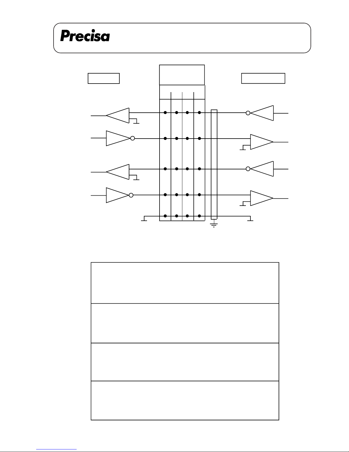
PHERIPERALS
CONNECTOR
MULTIPLEXER
4321
141414
RS 232 IN
12 9 18 15
25 22 6 3 CTS
DTR
CHANNELS
BALANCE
Female Interface-Connector (25-positions, D-submini)
Pin assignment
13 RS 232 Out
12 RS 232 In
23 CTS Channel 1 ---> Barcode reader
25 DTR
14 GND
10 RS 232 Out
9 RS 232 In
21 CTS Channel 2 ---> Printer
22 DTR
14 GND
19 RS 232 Out
18 RS 232 In
4 CTS Channel 3 ---> Reference
6 DTR (Printer II)
14 GND
16 RS 232 Out
15 RS 232 In
2 CTS Channel 4 ---> Barcode / Printer
3 DTR
14 GND
DTR242123CTS
16191013 RS 232 IN
14
A 09.04
RS 232 OUT
RS 232 OUT
Page 31
PAG OERLIKON AG
SERIES-300 S
ANALOGUE OUTPUT (350-8853)
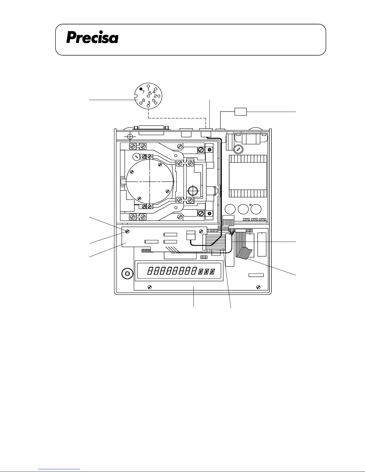
Key No. Part No. Description
1 350-7113 Cable
2 PN 1100-011 Screw M3x6
3 350-7229-010 D/A-board
4 PN 1048-009 Distance holder M3x20
5 350-4033-004 Label
6 350-8315 Connecting cable
[D]
[B]
[4]
[E]
[3]
[6]
[5]
[C]
[A]
6 Analogue output
2 GND
Analogue output 350-8853
[1,2]
A
nalo
g
out
A 10.01
Page 32
PAG OERLIKON AG
SERIES-300 S
ANALOGUE OUTPUT (350-8853)
Assembly instruction for analogue output
1. Lift the balance top, disconnect the flat wire [A] and remove the ovale data output cover plate in the rear
of the balance.
2. Insert the cable [1] through the opening and fix the plug with two screws [2].
3. Fix the D/A-board [3] with two distance holders [4] on the main board [D] (with two screws [E] from
the main board).
4. Connect the flat wire [B] on the main board [D].
5. Lead the cable [1] through the cable channel between the transformer and the crosswall from the
housing's bottom and connect it to the D/A-board [3].
6. Connect the cable [C].
7. Reassemble the balance, connect the flat wire [A] and mount the label [5].
Montage-Anleitung des Analogausgangs
1. Waagenoberteil abheben, Flachbandkabel [A] lösen und die ovale Datenausgang-Abdeckung auf der
Rückseite der Waage entfernen.
2. Kabel [1] durch die Öffnung führen und den Stecker mit den zwei Schrauben [2] befestigen.
3. D/A-Wandlerprint [3] mit zwei Distanzhaltern [4] auf den Hauptprint [D] schrauben (mit
den Schrauben [E] vom Hauptprint).
4. Flachbandkabel [B] am Hauptprint [D] anschliessen.
5. Kabel [1] durch den Kabelkanal zwischen dem Trafo und der Gehäuse-Trennwand durchführen und
mit dem D/A-Wandlerprint [3] verbinden.
6. Kabel [C] anschliessen.
7. Waage wieder zusammensetzen, Flachbandkabel [A] anschliessen und Schild [5] montieren.
A 10.02
Page 33
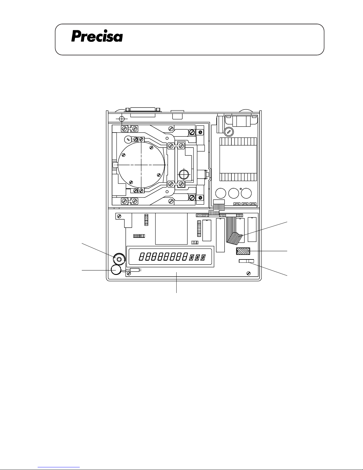
PAG OERLIKON AG
SERIES-300 S
ANALOGUE OUTPUT (350-8853)
Notice de montage pour analog output
1. Soulever la partie supérieure de la balance, débrancher le câble plat [A] et enlever le couvercle ovale de la
sortie de donées en arrière de la balance.
2. Insérer le câble [1] à travers de l'ouverture et fixer la fiche avec deux vis [2].
3. Fixer la carte imprimée D/A [3] avec deux ports de distance [4] à la carte principale [D] (avec deux vis
[E] de la carte principale).
4. Brancher le câble plat [B] à la carte principale [D].
5. Mener le câble [1] à travers du caniveau électrique entre le transformateur et la petite paroi de séparation
du boîtier intérieur et le brancher avec la carte imprimée D/A [3].
6. Brancher le câble [C].
7. Remonter la balance, connecter de nouveau le câble plat [A] et monter l'étiquette [5].
A 10.03
Page 34
PAG OERLIKON AG
SERIES-300 S
ANALOGUE OUTPUT (350-8853)
A 10.04
A N A L O G U E - O U T P U T
DIN Plug : GND -> Pin 2 IP 65 : GND -> 4
OUT -> Pin 6 OUT -> 1
Settings: - The analogue output can be defined at the end of the main menu.
It is possible to choose up to 6 different settings
Settings: - Hi-Speed -> Scale from 0 until max. 6.4 V. velocity 20 ms
- Lo-Speed 1 -> Digit 0 - 1 - 2 and signs are converted at +/- 9.99 V.,
velocity 80 ms, 160 ms or 320 ms.
- Lo-Speed 2 -> Digit 1 - 2 - 3 and signs are converted at
+/- 9.99 V., velocity 80 ms, 160 ms or 320 ms
- Lo-Speed 3 -> Digit 2 - 3 - 4 and signs are converted at
+/- 9.99 V, velocity 80 ms, 160 ms or 320 ms
- Lo-Speed 4 -> Digit 3 - 4 - 5 and signs are converted at
+/- 9.99 V., velocity 80 ms, 160 ms or 320 ms
- Lo-Speed 5 -> Scale from 0 until 10 V. velocity 80ms, 160 ms or 320 ms
Examples: ( 3'100 C )
Display 1 2 3 4, 5 6 g
Lo-speed 1 1 2 3 4, 5 6 g -> 4.56 V
Lo-speed 2 1 2 3 4, 5 6 g -> 3.45 V
Lo-speed 3 1 2 3 4, 5 6 g -> 2.34 V
Lo-speed 4 1 2 3 4, 5 6 g -> 1.23 V
Hi-Speed 1 2 3 4, 5 6 g -> appr.4.40 V
( 10’200 G )
Display 1 0 4 5 6 g
Lo-speed 1 1 0 4 5 6 g -> 4.56 V
Lo-speed 2 1 0 4 5 6 g -> 0.45 V
Lo-speed 3 1 0 4 5 6 g -> 1.04 V
Lo-speed 4 1 0 4 5 6 g -> 0.10 V
Hi-Speed 1 0 4 5 6 g -> appr.4.90 V
Page 35
PAG OERLIKON AG
SERIES-300 S
CLOCK (350-8871)
A 11.01
INSTALLATION INSTRUCTION FOR OPTION CLOCK 350-8871
[B]
[1]
[C]
[A]
[2]
Key No. Part No. Description
1 300-7060 NiCd-Accumulator
2 PN 3022-046 IC-RTC 72421 A
5
[D]
Page 36
PAG OERLIKON AG
SERIES-300 S
CLOCK (350-8871)
A 11.02
Einbauanleitung für Uhrenset
1. Waagenoberteil abheben und Flachbandkabel [A] lösen.
2. Akku [1] mit doppelseitigem Klebband an Gehäuse-Unterteil befestigen.
3. Stecker des Akkus am Hauptprint [C] anschliessen.
4. Uhrenbaustein [2] montieren (Markierung beachten).
5. DIL-Switch [D] Nr.5 auf Position ON stellen.
6. Waage wieder zusammensetzen und Flachbandkabel [A] anschliessen.
Notice d'installation pour le set de la montre
1. Soulever la partie supérieure de la balance et débrancher la câble plat [A].
2. Monter l'accu [1] avec la bande adhésive sur le bas du boîtier.
3. Connecter la fiche avec la carte principale [C].
4. Monter le CI de la montre [2] (respecter le marquage).
5. Mener le DIL-Switch [D] no.5 à la position ON.
5. Remonter la balance et connecter de nouveau le câble plat [A].
Installation instruction for clock
1. Lift the balance top and disconnect the flat wire [A].
2. Fix the accumulator [1] with the adhesive tape on the housing's bottom.
3. Connect the plug of the accumulator on the main board [C].
4. Mount the clock-IC [2] (take care of the mark).
5. Switch the DIL-Switch [D] no.5 to the position ON.
6. Reassemble the balance and connect the flat wire [A].
Page 37
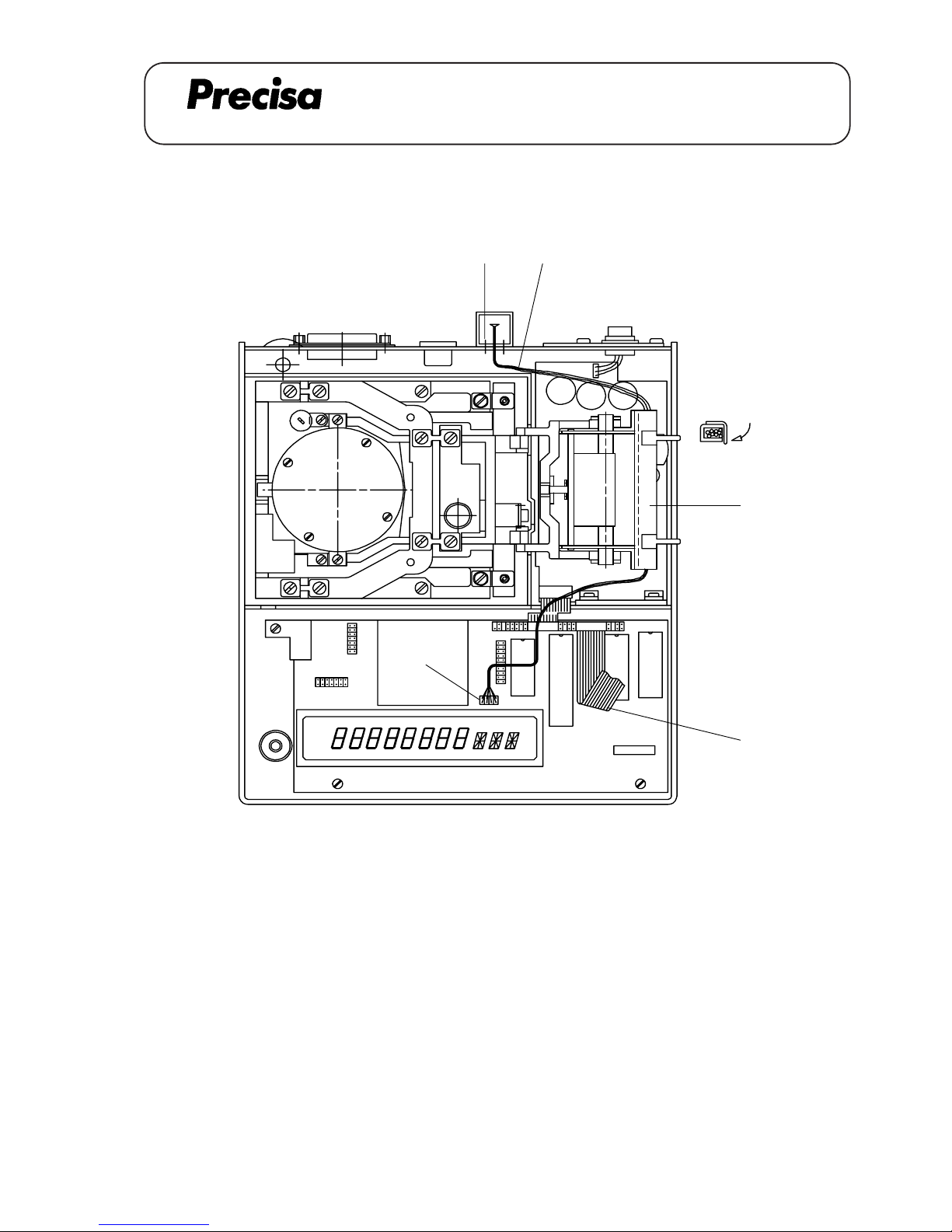
PAG OERLIKON AG
SERIES-300 SCS
REMOTE DISPLAY mounted to the balance (350-8876)
REMOTE DISPLAY mounted to the balance 350-8876
[B]
[1][2]
[3]
[A]
[4]
Key No. Part No. Description
1 350-9005 Remote display
2 PN 1100-058 Screw M3x10
3 350-8026 Cable channel
4 Clip (cable channel)
A 12.01
Page 38
PAG OERLIKON AG
SERIES-300 SCS
REMOTE DISPLAY mounted to the balance (350-8876)
Installation instruction for remote dispIay (mounted to the balance)
1. Lift the balance top, disconnect the flat wire [A] and remove the coverplate (small) from the data output
opening in the rear of the balance.
2. Mount the cable channel [3]. Lead the cable [1] through the opening and fix the display support with two
screws [2]. Lead the cable [1] through the cable channel and connect it to the plug [B] on top of the
display tube. Bend the clip [4] 90°.
3. Reassemble balance and connect the flat wire [A].
Einbauanleitung für Fernanzeige (am Gerät montiert)
1. Waagenoberteil abheben, Flachbandkabel [A] lösen und Datenausgang-Abdeckung (klein) auf der Rückseite der Waage entfernen.
2. Kabelkanal [3] montieren. Kabel [1] durch Öffnung führen und Fernanzeige-Stütze mit zwei Schrauben
[2] festschrauben. Kabel [1] durch den Kabelkanal durchführen und oberhalb der Anzeigeröhre an
Stecker [B] anschliessen. Klipp [4] 90° abbiegen.
3. Waage wieder zusammensetzen und Flachbandkabel [A] anschliessen.
Notice d’instaIIation pour I’affichage à distance (fixé à la balance)
1. Soulever la partie supérieure de la balance, débrancher le câble plat [A] et retirer le couvercle de la sortie
de données (petit) en arrière de la balance.
2. Monter le caniveau électrique [3]. Passer le câble [1] à travers de l’ouverture et fixer le support avec deux
vis [2]. Passer le câble [1] à travers du caniveau électrique et le brancher à la fiche [B]. Plier le clip [4]
90°.
3. Remonter la balance et connecter de nouveau le câble plat [A].
A 12.02
Page 39
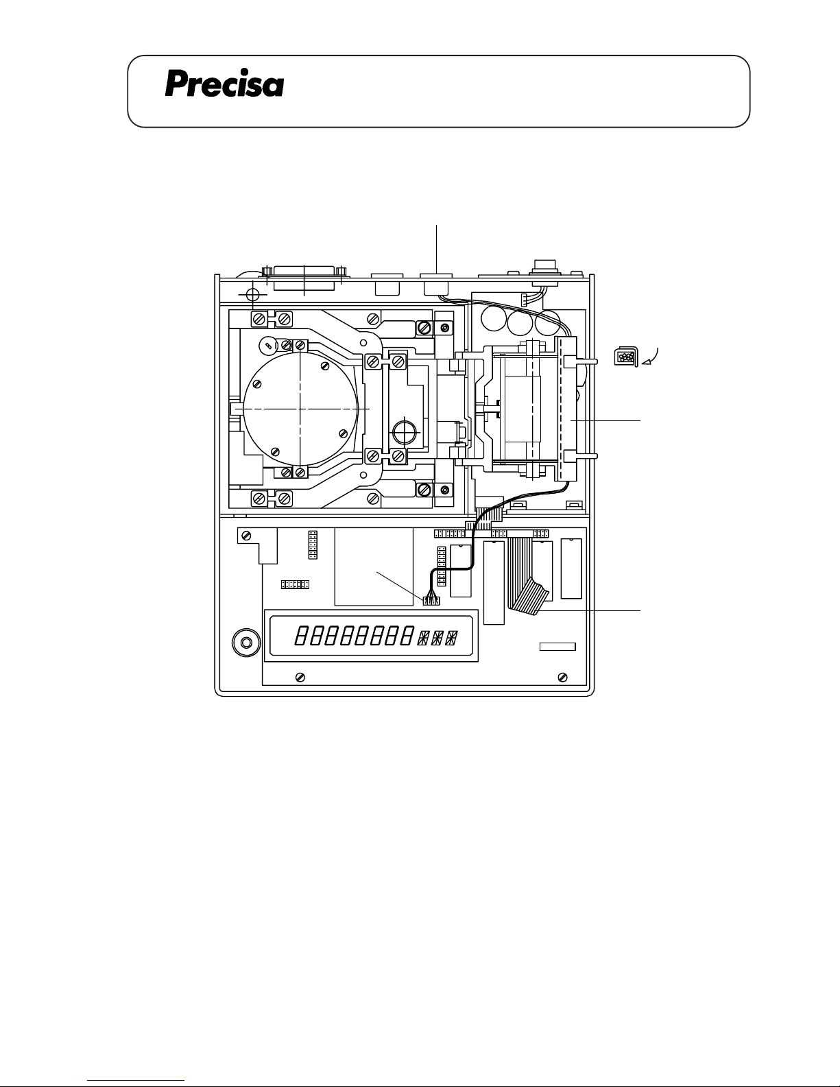
PAG OERLIKON AG
SERIES-300 SCS
CONNECTING CABLE
Remote display, freestanding / wall mounted (350-8877)
CONNECTING CABLE remote display freestanding / wall mounted 350-8877
[A]
[3]
[B]
[1,2]
[4]
Key No. Part No. Description
1 350-7152 Cable
2 PN 1100-011 Screw M3x6
3 350-8026 Cable channel
4 Clip (cable channel)
A 13.01
Page 40
PAG OERLIKON AG
SERIES-300 SCS
CONNECTING CABLE
Remote display, freestanding / wall mounted (350-8877)
Installation instruction for connecting cable (Remote Display; freestanding)
1. Lift the balance top, disconnect the flat wire [A] and remove the coverplate (small) from the data output
opening in the rear of the balance. Fix the cable channel [3].
2. Lead the cable [1] through the opening and fix the jack with two screws [2]. Lead the cable [1] through
the cable channel and connect it to the plug [B] on the top of the display tube. Bend the clip [4] 90°.
3. Reassemble the balance and connect the flat wire [A].
-> Part-No. for Remote Display (freestanding): 350-8873
Einbauanleitung für Verbindungskabel (Tischmodell von Fernanzeige)
1. Waagenoberteil abheben, Flachbandkabel [A] lösen und Datenausgang-Abdeckung (klein) auf der Rückseite der Waage entfernen. Kabelkanal [3] montieren.
2. Kabel [1] durch Öffnung führen und Buchse mit zwei Schrauben [2] festschrauben. Kabel [1] durch den
Kabelkanal durchführen und oberhalb der Anzeigeröhre an Stecker [B] anschliessen. Klipp [4] 90°
umbiegen.
3. Waage wieder zusammensetzen und Flachbandkabel [A] anschliessen.
-> Bestellnummer für Fernanzeige (freistehend): 350-8873
Notice d’instaIIatIon pour le câble de jonction (modèle de tabIe de l'affichage à distance)
1. Soulever la partie supérieure de la balance, débrancher le câble plat [A] et retirer le couvercle de la sortie
de données (petit) en arrière de la balance. Monter le caniveau électrique [3].
2. Passer le câble [1] à travers de l’ouverture et fixer la douille avec deux vis [2]. Passer le câble [1] à
travers du caniveau électrique et le brancher à la fiche [B]. Plier le clip [4] 90°.
3. Remonter la balance et connecter de nouveau le câble plat.
-> Numéro de commande pour l'affichage à distance (modèle de table): 350-8873
A 13.02
Page 41
PAG OERLIKON AG
SERIES-300 SCS
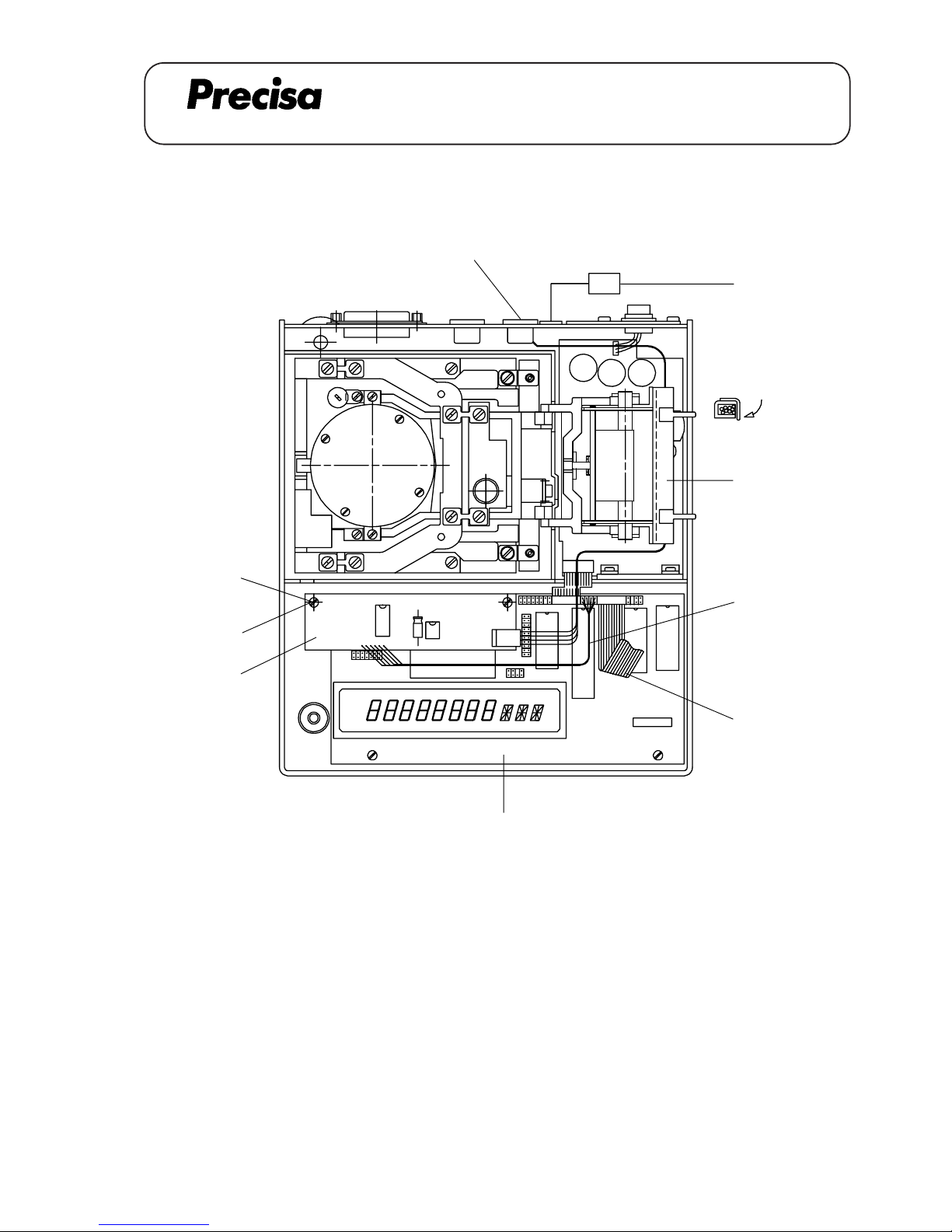
DATA OUTPUT 20mA current loop, bi-directional (350-8878)
DATA OUTPUT 20mA current loop, bi-directional 350-8878
[D]
[C]
[4]
[B]
[3]
[6]
[5]
[1,2]
Key No. Part No. Description
1 350-7153 Cable
2 PN 1100-011 Screw M3x6
3 350-7211-010 Data output board
4 PN 1048-009 Distance holder M3x20
5 350-8026 Cable channel
6 350-4033-001 Label
7 Clip (cable channel)
[A]
CL
[7]
A 14.01
Page 42
PAG OERLIKON AG
SERIES-300 SCS
DATA OUTPUT 20mA current loop, bi-directional (350-8878)
Istallation instruction for data output (20mA current loop)
1. Lift the balance top, disconnect the flat wire [D] and remove the coverplate from the data output opening in
the rear of the balance. Fix the cable channel [5].
2. Lead the cable [1] through the opening and fix the data output plug with two screws [2]. Lead the cable
[1] through the cable channel and plug it to the data output board [3]. Bend the clip [7] 90°.
3. Fix the data output board [3] with two distance holders [4] on the main board [A] (with two screws [B]
from the main board). Connect the data output cable [C] on the main board [A].
4. Reassemble the balance, connect the flat wire [D] and mount the label [6].
For further informations about type of data transmission and remote control commands see chapter 11.
Einbauanleitung für Datenausgang (20mA current loop)
1. Waagenoberteil abheben, Flachbandkabel [D] lösen und Datenausgang-Abdeckung auf Rückseite der
Waage entfernen. Kabelkanal [5] montieren.
2. Kabel [1] durch Öffnung führen und Stecker mit zwei Schrauben [2] festschrauben. Kabel [1] durch
den Kabelkanal [5] durchführen und mit Datenausgangsprint [3] verbinden. Klipp [7] 90° abbiegen.
3. Datenausgangsprint [3] mit zwei Distanzhaltern [4] auf dem Hauptprint [A] befestigen (mit Schrauben
[B] vom Hauptprint). Datenausgangs-Kabel [C] mit Hauptprint [A] verbinden.
4. Waage wieder zusammensetzen, Flachbandkabel [D] anschliessen und Schild [6] montieren.
Für weitere informationen über Art der Datenübertragung und über Fernsteuerbefehle siehe Kapitel 11.
Notice d’installation pour la sortie de données (boucle de courant 20mA)
1. Soulever la partie supérieure de la balance, débrancher le câble plat [D] et retirer le couvercle de la sortie
de données en arrière de la balance. Monter le caniveau électrique [5].
2. Passer le câble [1] à travers de l’ouverture et fixer la fiche avec deux vis [2]. Passer le câble [1] à
travers du caniveau électrique [5] et le relier avec la carte de la sortie de données [3]. Plier le clip [7]
90°.
3. Fixer la carte de la sortie de données [3] avec deux ports de distance [4] à la carte principale [A] (avec
deux vis [B] de la carte principale). Relier le câble [C] de la sortie de données avec la carte principale
[A].
4. Remonter à nouveau la balance, connecter le câble plat [D] et monter l'étiquette [6].
Plus d'informations du type de transfert de donées et des ordres de commande à distance voire chapitre 11.
A 14.02
Page 43
PAG OERLIKON AG
SERIES-300 SCS
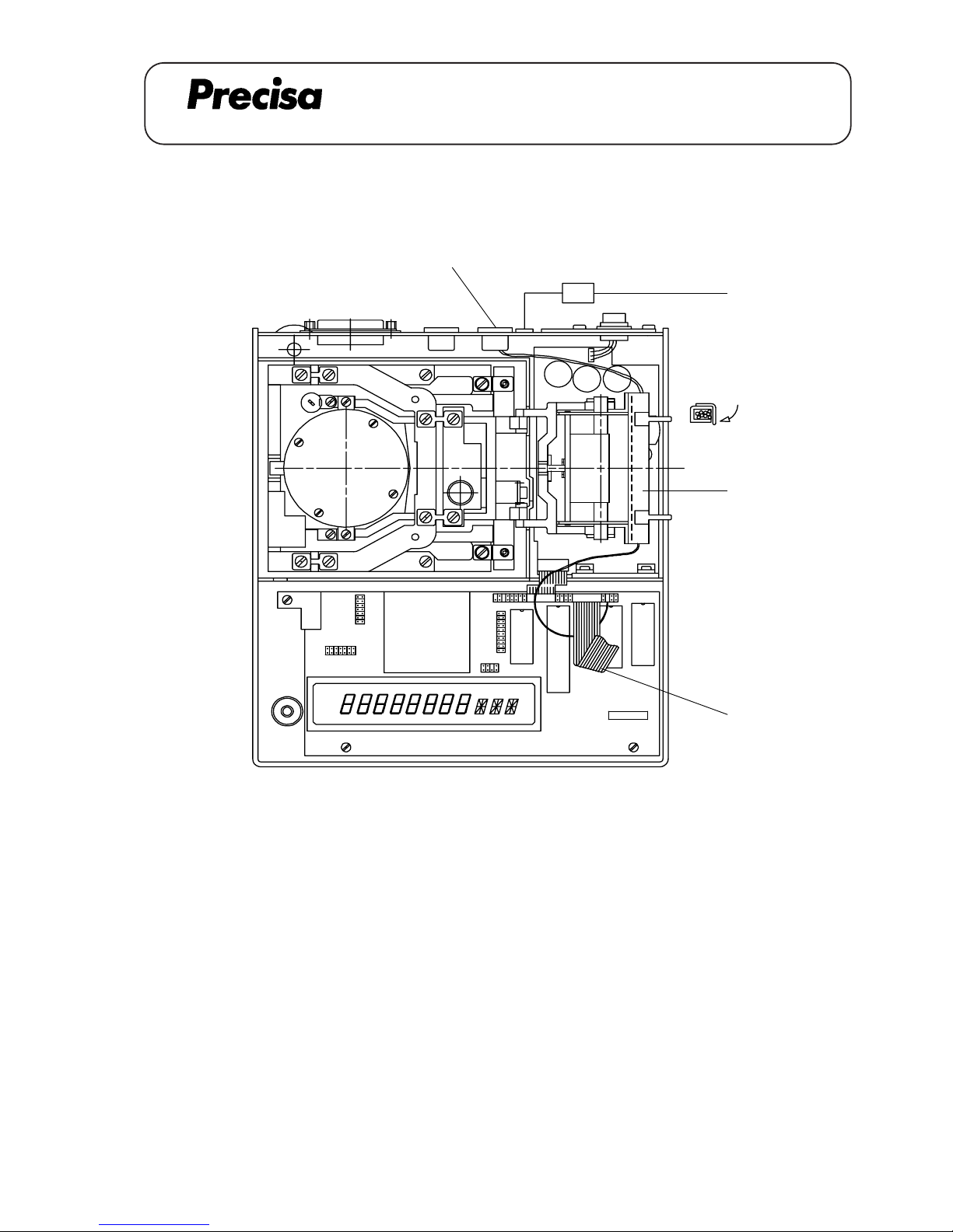
CONNECTING CABLE external T-Key (350-8879)
CONNECTING CABLE external T-Key 350-8879
[1,2]
ex-T
[4]
[A]
[3]
[5]
Key No. Part No. Description
1 350-7154 Cable
2 PN 1100-011 Screw M3x6
3 350-8026 Cable channel
4 350-4033-003 Label
5 Clip (cable
channel)
A 15.01
Page 44
PAG OERLIKON AG
SERIES-300 SCS
CONNECTING CABLE external T-Key (350-8879)
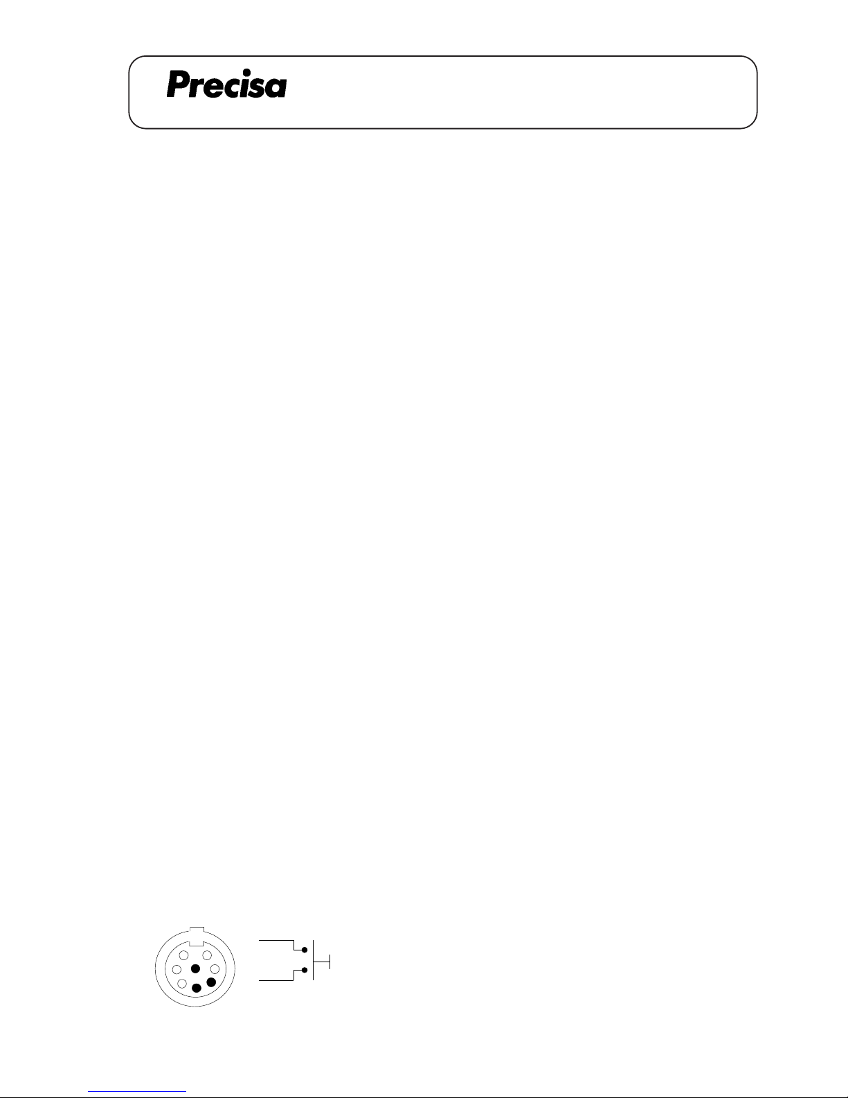
Installation instruction for connecting cable (external T-key)
1. Lift the balance top, disconnect the flat wire [A] and remove the coverplate from the data output opening in
the rear of the balance.
2. Lead the cable [1] through the opening and fix the analogue output plug with two screws [2]. Fix the cable
channel [3].
3. Lead the cable [1] through the cable channel and plug it to the pin-type socket. Bend the clip [5] 90°.
4. Reassemble the balance, connect the flat wire [A] and mount the label [4].
-> Part-No. for external T-key: 350-8904
Notice d’installation pour Ia câble de jonction (touche-T externe)
1. Soulever la partie supérieure de la balance, débrancher le câble plat [A] et retirer le couvercle de la sortie
de données en arrière de la balance.
2. Passer le câble [1] à travers de l’ouverture et fixer la fiche avec deux vis [2]. Monter le caniveau
électrique [3].
3. Passer le câble [1] à travers du caniveau électrique et le relier avec le culot à ergots. Plier le clip [5] 90°.
4. Remonter la balance, connecter de nouveau le câble plat [A] et monter l'étiquette [4].
-> Numéro de commande pour la touche T externe: 350-8904
Einbauanleitung für Verbindungskabel (externe T-Taste)
1. Waagenoberteil abheben, Flachbandkabel [A] lösen und Datenausgang-Abdeckung auf Rückseite der
Waage entfernen.
2. Kabel [1] durch Öffnung führen und Stecker mit zwei Schrauben [2] festschrauben. Kabelkanal [3]
befestigen.
3. Kabel [1] durch den Kabelkanal durchführen und auf Stiftleiste stecken. Klipp [5] 90° abbiegen.
4. Waage wieder zusammensetzen, Flachbandkabel [A] anschliessen und Schild [4] befestigen.
-> Bestellnummer für externe T-Taste: 350-8904
Tare
4
6
2
2
6
4 Code
A 15.02
Page 45
PAG OERLIKON AG
SERIES-300 SCS
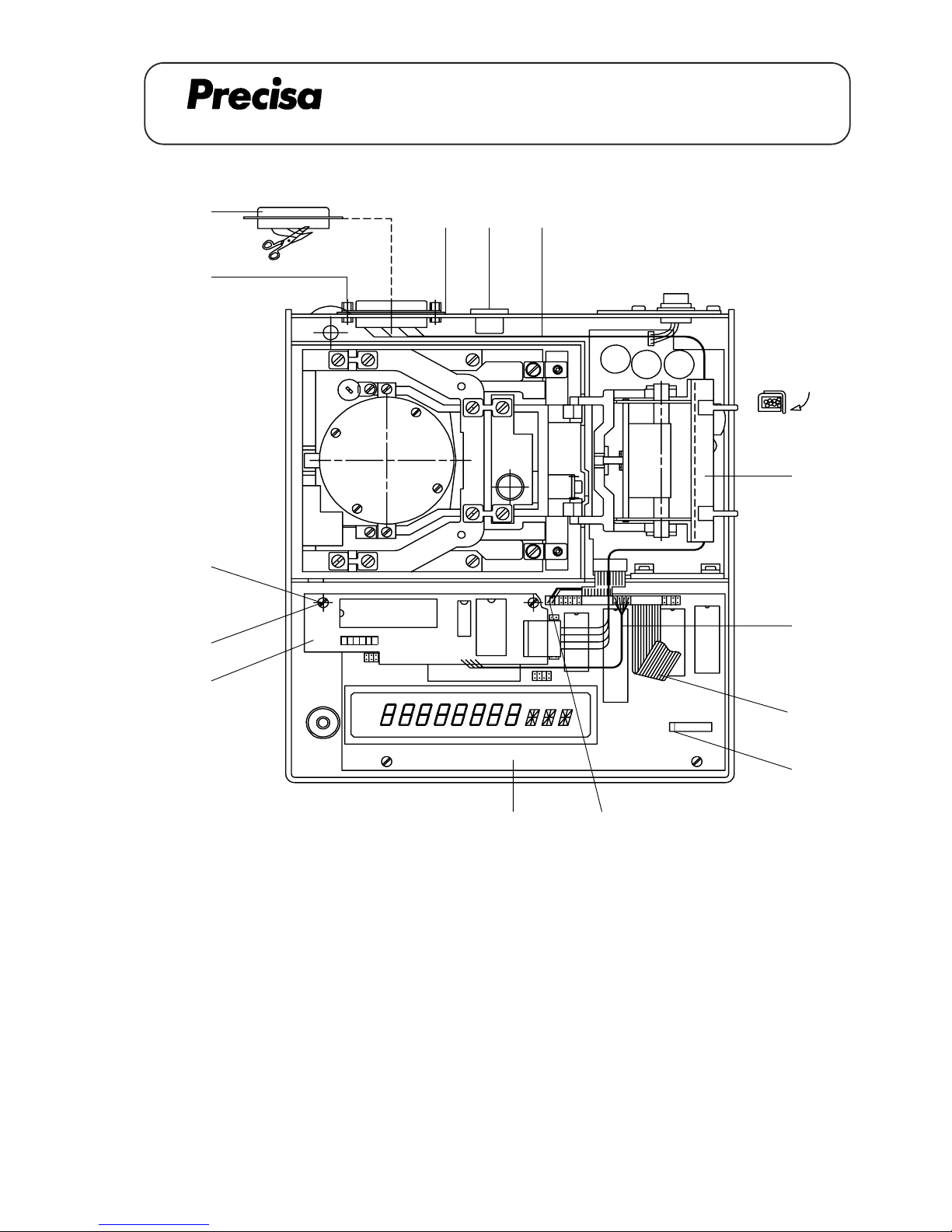
DATA OUTPUT IEC 625 / IEEE 488 (350-8880 / 8881)
A 16.01
DATA OUTPUT IEC 625 / IEEE 488 350-8880 / 8881
IEEE 488
Key No. Part No. Description
1 350-7156 Cable
2 350-3015 Special screw
PN 1300-003 Nut
PN 1500-030 Washer
PN 1500-034 Spring washer
3 350-7210-010 Data output board
4 PN 1048-009 Distance holder M3x20
5 350-8026 Cable channel
7 Clip (cable channel)
IEC 625
Key No. Part No. Description
1 350-7155 Cable
2 350-3004 Special screw
PN 1300-003 Nut
PN 1500-030 Washer
PN 1500-034 Spring washer
3 350-7210-010 Data output board
4 PN 1048-009 Distance holder M3x20
5 350-8026 Cable channel
6 350-4015 Cover
7 Clip (cable channel)
[F]
[C]
[6]
[A]
[1]
[2]
[G]
[4]
[B]
[3]
[7]
[5]
[D]
[E]
1
[H]
Page 46
PAG OERLIKON AG
SERIES-300 SCS
DATA OUTPUT IEC 625 / IEEE 488 (350-8880 / 8881)
A 16.02
Assembly instruction for the data output IEC 625 / IEEE 488
1. Lift the balance top and disconnect the flat wire [E].
2. Dismantle the jack [A] and pull it out a little bit. Unplug the plug [F].
3. Dismantle the data output RS 232 [G] and cut 3 wires (stay in the balance).
4. Fix the cover [6] on the plug (only IEC 625). Lead the cable [1] through the opening and fix the plug with
two screws [2]. Secure it with the nut, the washer and the spring washer.
5. Mount the cable channel [5]. Lead the cable [1] through the cable channel and connect it to the data
output board [3]. Bend the clip [7] 90°.
6. Fix the data output board [3] with two distance holders [4] on the main board [C] (with two screws [B]
from the main board). Bring the cable [1] according to the drawing on page 1 in place (do not jam any
wires).
7. Connect the cable [D] and fix the jack [A].
8. Switch the DIL-Switch [H] no.1 to the position ON.
9. Reassemble the balance and connect the flat wire [E].
Montage-Anleitung für Datenausgang IEC 625 / IEEE 488
1. Waagenoberteil abheben und Flachbandkabel [E] lösen.
2. Buchse [A] demontieren und etwas herausziehen. Stecker [F] ziehen.
3. Datenausgang RS 232 [G] demontieren und 3 Litzen abklemmen (bleiben in der Waage).
4. Abdeckung [6] auf die Steckerbuchse klemmen (nur IEC 625). Kabel [1] durch die Öffnung führen und
den Stecker mit zwei Schrauben [2] festschrauben. Mit 6-kt Mutter, U-Scheibe und Federring sichern.
5. Kabelkanal [5] montieren. Kabel [1] durch den Kabelkanal führen und mit dem Print [3] verbinden. Klipp
[7] 90° abbiegen.
6. Print [3] mit zwei Distanzhaltern [4] auf den Hauptprint [C] schrauben (mit Schrauben [B] vom
Hauptprint). Kabel [1] genau nach Zeichnung Seite 1 verlegen (keine Litzen einklemmen).
7. Kabel [D] anschliessen und Buchse [A] wieder befestigen.
8. DIL-Switch [H] Nr.1 auf Position ON stellen.
9. Waage wieder zusammensetzen und Flachbandkabel [E] anschliessen.
Page 47
PAG OERLIKON AG
SERIES-300 SCS
DATA OUTPUT IEC 625 / IEEE 488 (350-8880 / 8881)
A 16.03
Notice d'installation pour la sortie de donées IEC 625 / IEEE 488
1. Soulever la partie supérieure de la balance et débrancher le câble plat [E].
2. Démonter la douille [A] et la retirer un peu. Retirer la fiche [F].
3. Démonter la sortie de donées RS 232 [G] et débrancher 3 cordons (restes dans la balance).
4. Serrer le couvercle [6] sur la fiche (seulement IEC 625). Passer le câble [1] à travers de l'ouverture et
fixer la fiche avec deux vis [2]. Les arrêter avec l'ecrou, la rondelle et la rondelle ressort.
5. Monter le caniveau électrique [5]. Passer le câble [1] à travers du caniveau électrique et le connecter
avec la carte de la sortie de donées [3]. Plier le clip [7] 90°.
6. Fixer la carte de la sortie de donées [3] avec deux ports de distance [4] sur la carte principale [C]
(avec deux vis [B] de la carte principale). Insérer le câble [1] selon le dessin page 1 (ne coincer pas
des cordons).
7. Connecter le câble [D] et remonter la douille [A].
8. Mener le DIL-Switch [H] no.1 à la position ON.
9. Remonter la balance et connecter de nouveau le câble plat [E].
Page 48
PAG OERLIKON AG
SERIES-300 SCS
DATA OUTPUT IEC 625 / IEEE 488 (350-8880 / 8881)
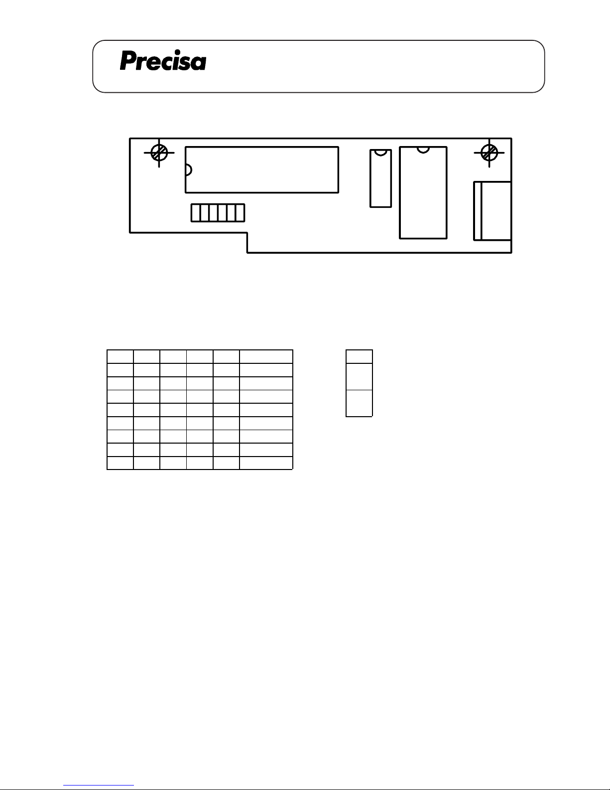
Switch settings (on = 1)
Address switch Capital switch
1 2 3 4 5 Address 6
0 0 0 0 0 0 Capital / small letters
1 0 0 0 0 1 0 off : g dwt ozt KT pcs
0 1 0 0 0 2 Capital letters
11000 3 1 on :GDWTOZTKTPCS
00100 4
01111 30
11111 31
1
2
45
6 3
A 16.04
Page 49
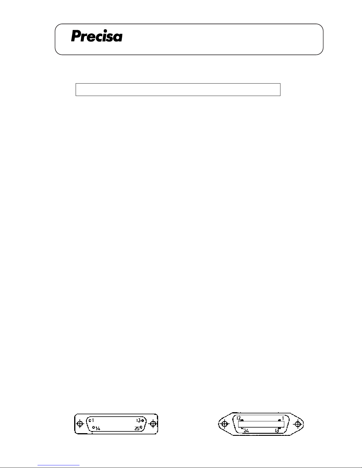
PAG OERLIKON AG
SERIES-300 SCS
DATA OUTPUT IEC 625 / IEEE 488 (350-8880 / 8881)
Datatransfer sequence (total 16 characters in 7 bit-ASCII-code)
Blanks transmitted, if : - leading zeroes
- no decimal point
- no units (instability is greater than the selected stability)
Examples for datatransfer
12345678910111213141516
+ 1247,68 g + 1 2 4 7 . 6 8 g CR LF
+ 802,28 dwt + 8 0 2 . 2 8 d w t CR LF
+ 4,011 ozt + 4 . 0 1 1 o z t CR LF
+ 48216 pcs + 4 8 2 1 6 p c s CR LF
Over Load OL
Under Load UL
IEC 625
Contact Signal Contact Signal
1 DIO 1 14 DIO 5
2 DIO 2 15 DIO 6
3 DIO 3 16 DIO 7
4 DIO 4 17 DIO 8
5 REN 18 GND (5)
6 EOI 19 GND (6)
7 DAV 20 GND (7)
8 NRFD 21 GND (8)
9 NDAC 22 GND (9)
10 IFC 23 GND (10)
11 SRQ 24 GND (11)
12 ATN 25 GND (12)
13 shield
IEEE 488
Contact Signal Contact Signal
1 DIO 1 14 DIO 6
2 DIO 2 15 DIO 7
3 DIO 3 16 DIO 8
4 DIO 4 17 REN
5 EOI 18 GND
6 DAV 19 GND
7 NRFD 20 GND
8 NDAC 21/ GND
9 IFC 22 GND
10 SRQ 23 GND
11 ATN 24 GND
12 shield
13 DIO 5
S D6D5DPD4D3D2D1D0B B U U U CFLF
12345678910111213141516
B = Blank
S = Sign (+ or - or blank)
DP = Decimal Point (can be anywhere between D0 and D6)
U = Unit
CR = Carriage Return
LF = Line Feed with EOI
A 16.05
Page 50
SERIES-300 SCS
PAG OERLIKON AG
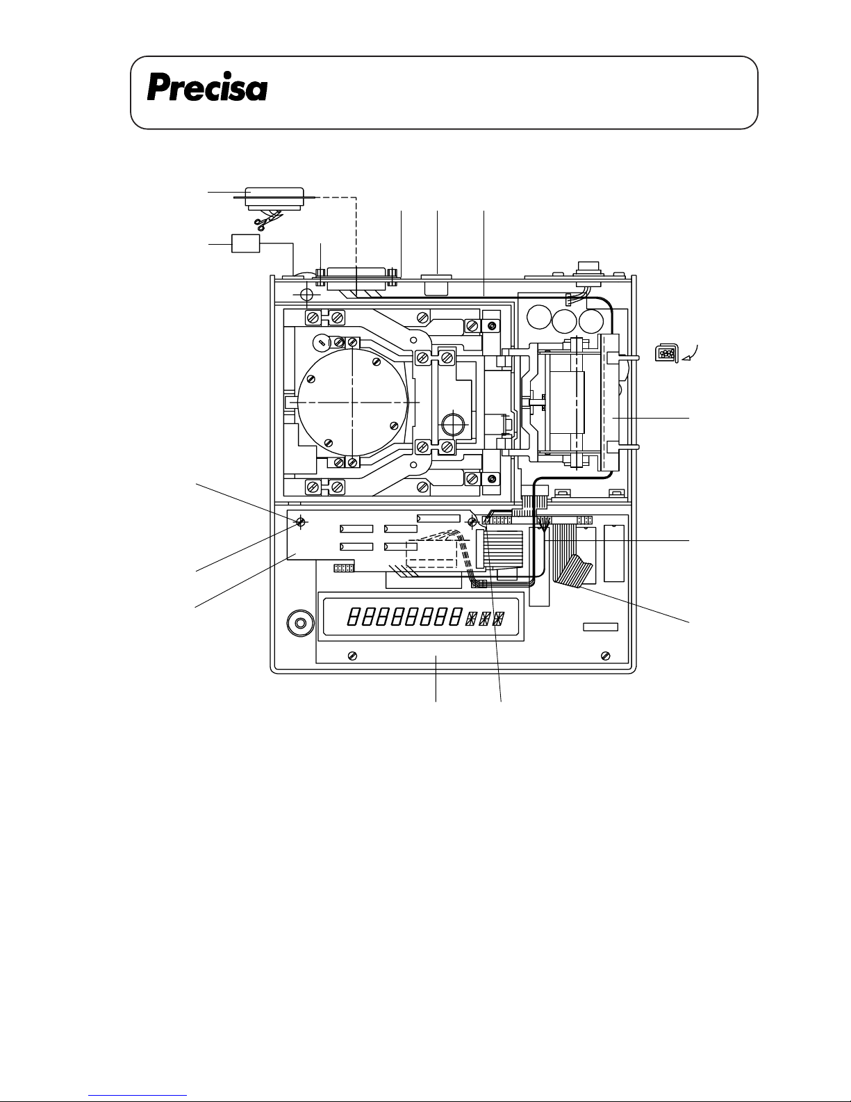
DATA OUTPUT 4-CHANNEL MULTIPLEXER (350-8882)
Data output 4-channel multiplexer 350-8882
[4]
[3]
[E]
[5]
[D]
[6]
[1] [B] [2]
[F]
[7]
[A]
[C][G]
Multi-P
[8]
Key No. Part No. Description
1 350-4015 Cover
2 350-7157 Connecting cable
3 350-7228-010 Multiplexer-board
4 PN 1048-009 Distance holder M3x20
5 350-4047-001 Label for Multiplexer-output
6 350-3014 Special screw
PN 1300-003 Nut
PN 1500-030 Washer
PN 1500-034 Spring washer
7 350-8026 Cable channel
8 Clip (cable channel)
A 17.01
Page 51
SERIES-300 SCS
PAG OERLIKON AG
DATA OUTPUT 4-CHANNEL MULTIPLEXER (350-8882)
Montage-Anleitung für 4-Kanal Multiplexer
1. Waagenoberteil abheben und Flachbandkabel [A] lösen.
2. Buchse [B] demontieren und etwas herausziehen. Stecker [C] ziehen.
3. Datenausgang RS 232 [D] demontieren, 3 Litzen abklemmen (bleiben in der Waage).
4. Abdeckung [1] auf den Multiplexer-Stecker klemmen, Kabel [2] durch die Öffnung führen und den
Stecker mit zwei Schrauben [6] festschrauben. Mit 6-kt Mutter, U-Scheibe und Federscheibe
sichern.
5. Kabelkanal [7] montieren. Kabel [2] durch den Kabelkanal [7] durchführen und mit dem
Multiplexer-Print [3] verbinden. Klipp [8] 90° abbiegen.
6. Multiplexer-Print [3] mit zwei Distanzhaltern [4] auf den Hauptprint [G] schrauben (mit den
Schrauben [E] vom Hauptprint). Kabel [2] genau nach Zeichnung Seite 1 verlegen (keine Litzen
einklemmen).
7. Kabel [F] anschliessen und Buchse [B] wieder befestigen.
8. Waage wieder zusammensetzen und Flachbandkabel [A] anschliessen.
9. Schild für Multiplexer-Ausgang [5] auf die Gehäuse-Rückwand kleben.
Assembly instructions for the 4-channel multiplexer
1. Lift the balance top and disconnect the flat wire [A].
2. Dismantle the jack [B] and pull it out a little bit. Unplug the plug [C].
3. Dismantle the data output RS 232 [D] and cut 3 wires (stay in the balance).
4. Fix the cover [1] on the multiplexer plug, lead the cable [2] through the opening and fix the plug with two
screws [6]. Secure it with the nut, the washer and the spring washer.
5. Mount the cable channel [7]. Lead the cable [2] through the cable channel and plug it to the multiplexer
board [3]. Bend the clip [8] 90°.
6. Fix the multiplexer board [3] with two distance holders [4] on the main board [G] (with two screws [E]
from the main board). Bring the cable [2] according to the drawing on page 1 in place (do not jam any
wires).
7. Connect the cable [F] and fix the jack [B].
8. Reassemble the balance and connect the flat wire [A].
9. Stick the label for the multiplexer output [5] on the backside of the housing.
A 17.02
Page 52
SERIES-300 SCS
PAG OERLIKON AG
DATA OUTPUT 4-CHANNEL MULTIPLEXER (350-8882)
Notice d'installation pour 4-canal multiplexer
1. Soulever la partie supérieure de la balance et débrancher le câble plat [A].
2. Démonter la douille [B] et la retirer un peu. Retirer la fiche [C].
3. Démonter la sortie de donées RS 232 [D] et débrancher 3 cordons (restes dans la balance).
4. Serrer le couvercle [1] sur la fiche du multiplexer, passer le câble [2] à travers de l'ouverture et fixer la
fiche avec deux vis [6]. Les arrêter avec l'ecrou, la rondelle et la rondelle ressort.
5. Monter le caniveau électrique [7]. Passer le câble [2] à travers du caniveau électrique et le connecter
avec la carte de multiplexer [3]. Plier le clip [8] 90°.
6. Fixer la carte de multiplexer [3] avec deux ports de distance [4] sur la carte principale [G] (avec deux
vis [E] de la carte principale). Insérer le câble [2] selon le dessing page 1 (ne coincer pas des
cordons).
7. Connecter le câble [F] et remonter la duille [B].
8. Remonter la balance et connecter de nouveau le câble plat [A].
9. Coller l'étiquette pour le multiplexer output [5] au dos du boîtier.
A 17.03
Page 53
SERIES-300 SCS
PAG OERLIKON AG
DATA OUTPUT 4-CHANNEL MULTIPLEXER (350-8882)
Female Interface-Connector (25-positions, D-submini)
Pin assignment
13 RS 232 Out
12 RS 232 In
23 CTS Channel 1 ---> Barcode reader
25 DTR
14 GND
10 RS 232 Out
9 RS 232 In
21 CTS Channel 2 ---> Printer
22 DTR
14 GND
19 RS 232 Out
18 RS 232 In
4 CTS Channel 3 ---> Reference
6 DTR (Printer II)
14 GND
16 RS 232 Out
15 RS 232 In
2 CTS Channel 4 ---> Barcode / Printer
3 DTR
14 GND
PHERIPERALS
CONNECTOR
MULTIPLEXER
4321
141414
RS 232 IN
12 9 18 15
25 22 6 3 CTS
DTR
CHANNELS
BALANCE
DTR242123CTS
16191013 RS 232 IN
14
A 17.04
RS 232 OUT
RS 232 OUT
Page 54
PAG OERLIKON AG
SERIES-300 SCS
ANALOGUE OUTPUT (350-8883)
Analogue output 350-8883
Key No. Part No. Description
1 350-7158 Cable
2 PN 1100-011 Screw M3x6
3 350-7229-010 D/A-board
4 PN 1048-009 Distance holder M3x20
5 350-4033-004 Label
6 350-8026 Cable channel
7 350-8315 Connecting cable
8 Clip (cable channel)
[5]
[6]
[C]
[A]
[7]
[4]
[E]
[3]
[D]
[B]
6 Analogue output
2 GND
[8]
[1,2]
Analog
out
A 18.01
Page 55
PAG OERLIKON AG
SERIES-300 SCS
ANALOGUE OUTPUT (350-8883)
Assembly inctruction for analogue output
1. Lift the balance top, disconnect the flat wire [A] and remove the ovale data output cover plate in the
rear of the balance.
2. Insert the cable [1] through the opening and fix the plug with two screws [2].
3. Fix the D/A-board [3] with two distance holders [4] on the main board [D] (with two screws [E]
from the main board).
4. Connect the flat wire [B] on the main board [D].
5. Mount the cable channel [6]. Lead the cable [1] through the cable channel and connect it to the D/Aboard [3]. Bend the clip [8] 90°.
6. Connect the cable [C].
7. Reassemble the balance, connect the flat wire [A] and mount the label [5].
Montage-Anleitung des Analogausgangs
1. Waagenoberteil abheben, Flachbandkabel [A] lösen und die ovale Datenausgang-Abdeckung auf der
Rückseite der Waage entfernen.
2. Kabel [1] durch die Oeffnung führen und den Stecker mit den zwei Schrauben [2] befestigen.
3. D/A-Wandlerprint [3] mit zwei Distanzhaltern [4] auf den Hauptprint [D] schrauben (mit den
Schrauben [E] vom Hauptprint).
4. Flachbandkabel [B] am Hauptprint [D] anschliessen.
5. Kabelkanal [6] montieren. Kabel [1] durch den Kabelkanal durchführen und mit dem D/A-
Wandlerprint [3] verbinden. Klipp [8] 90° umbiegen.
6. Kabel [C] anschliessen.
7. Waage wieder zusammensetzen, Flachbandkabel [A] anschliessen und Schild [5] montieren.
A 18.02
Page 56
PAG OERLIKON AG
SERIES-300 SCS
ANALOGUE OUTPUT (350-8883)
Notice de montage pour la sortie analogique
1. Soulever la partie supérieure de la balance, débrancher le câble plat [A] et enlever le couvercle
ovale de la sortie de donées en arrière de la balance.
2. Insérer le câble [1] à travers de l'ouverture et fixer la fiche avec deux vis [2].
3. Fixer la carte imprimée D/A [3] avec deux ports de distance [4] à la carte principale [D] (avec
deux vis [E] de la carte principale).
4. Brancher la câble plat [B] à la carte principale [D].
5. Monter le caniveau électrique [6]. Mener le câble [1] à travers du caniveau électrique et le brancher
avec la carte imprimée D/A [3]. Plier le clip [8] 90°.
6. Brancher le câble [C].
7. Remonter la balance,connecter de nouveau le câble plat [A] et monter l'étiquette [5].
A 18.03
Page 57
PAG OERLIKON AG
SERIES-300 SCS
ANALOGUE OUTPUT (350-8883)
A N A L O G U E - O U T P U T
DIN Plug : GND -> Pin 2 IP 65 : GND -> 4
OUT -> Pin 6 OUT -> 1
Settings: - The analogue output can be defined at the end of the main menu.
It is possible to choose up to 6 different settings
Settings: - Hi-Speed -> Scale from 0 until max. 6.4 V, velocity 20 ms
- Lo-Speed 1 -> Digit 0 - 1 - 2 and signs are converted at +/- 9.99 V,
velocity 40 / 80 / 160 / 320 ms
- Lo-Speed 2 -> Digit 1 - 2 - 3 and signs are converted at
+/- 9.99 V, velocity 40 / 80 / 160 / 320 ms
- Lo-Speed 3 -> Digit 2 - 3 - 4 and signs are converted at
+/- 9.99 V, velocity 40 / 80 / 160 / 320 ms
- Lo-Speed 4 -> Digit 3 - 4 - 5 and signs are converted at
+/- 9.99 V, velocity 40 / 80 / 160 / 320 ms
- Lo-Speed 5 -> Scale from 0 until 10 V, velocity 40 / 80 / 160 / 320 ms
Examples: ( 2'200 C )
Display 1 2 3 4, 5 6 g
Lo-speed 1 1234,5 6 g -> 4.56 V
Lo-speed 2 1234,5 6 g -> 3.45 V
Lo-speed 3 1234,5 6 g -> 2.34 V
Lo-speed 4 1 2 3 4, 5 6 g -> 1.23 V
Hi-Speed 1234,5 6 g -> appr.4.40 V
(12'400 DG-FR )
Display 10456 g
Lo-speed 1 10456 g -> 5.6 V
Lo-speed 2 10456 g -> 4.56 V
Lo-speed 3 10456 g -> 0.45 V
Lo-speed 4 10456 g -> 1.04 V
Hi-Speed 10456 g -> appr. 4.90 V
( 12’100 G )
Display 1 0456 g
Lo-speed 1 1 0 4 5 6 g -> 4.56 V
Lo-speed 2 1 0456 g -> 0.45 V
Lo-speed 3 1 0456 g -> 1.04 V
Lo-speed 4 1 0456 g -> 0.10 V
Hi-Speed 1 0456 g -> appr. 4.90 V
A 18.04
Page 58
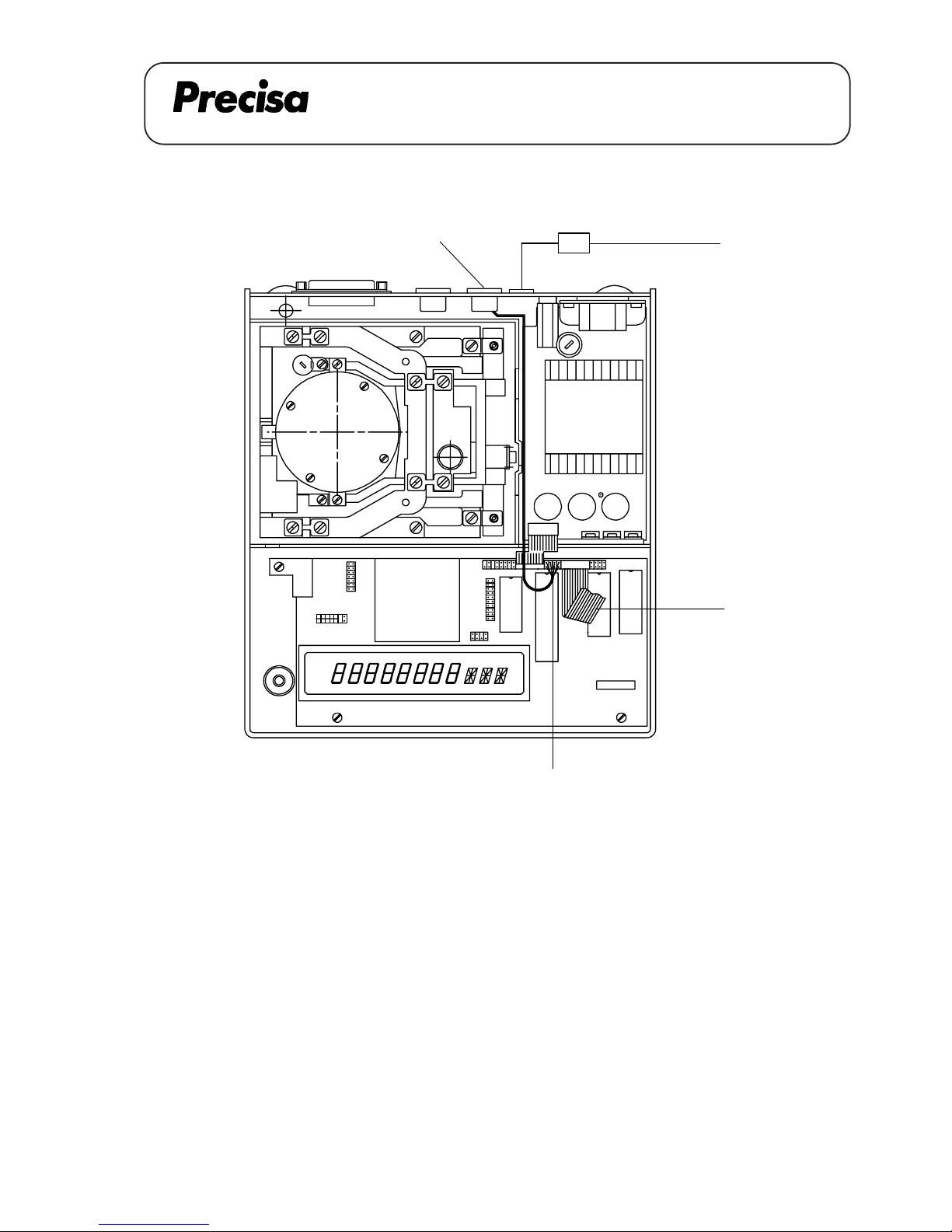
PAG OERLIKON AG
SERIES-300 S
INTERFACE HA 300 (350-8886)
Key No. Part No. Description
1 350-7127 Cable
2 PN 1100-011 Screw M3x6
3 350-4047-007 Label
Interface HA 300 350-8886
[3]
[A]
[B]
[1,2]
HA 300
A 19.01
Page 59
PAG OERLIKON AG
SERIES-300 S
INTERFACE HA 300 (350-8886)
Assembly instruction for the data output HA 300
1. Lift the balance top, disconnect the flat wire [A] and remove the cover plate in the rear of the balance.
2. Insert the cable [1] through the opening and fix the plug with two screws [2].
3. Lead the cable [1] through the cable channel between the transformer and the crosswall from the
housing's bottom and connect it to the plug [B].
4. Reassemble the balance, connect the flat wire [A] and mount the label [3].
Montage-Anleitung des Datenausgangs für HA 300
1. Waagenoberteil abheben, Flachbandkabel [A] lösen und Datenausgang-Abdeckung auf Rückseite
der Waage entfernen.
2. Kabel [1] durch die Öffnung führen und den Stecker mit den zwei Schrauben [2] befestigen.
3. Kabel [1] durch den Kabelkanal zwischen dem Trafo und der Gehäuse-Trennwand durchführen und
mit Stecker [B] verbinden.
4. Waage wieder zusammensetzen, Flachbandkabel [A] anschliessen und Schild [3] montieren.
Notice d'installation pour la sortie de donées HA 300
1. Soulever la partie supérieure de la balance, débrancher le câble plat [A] et retirer le couvercle de la
sortie de donées en arrière de la balance.
2. Passer le câble [1] à travers de l'ouverture et fixer la fiche avec deux vis [2].
3. Passer le câble [1] dans le caniveau électrique entre le transformateur et la closion de séparation du
boîtier et le relier avec la fiche [B].
4. Remonter la balance, connecter la câble plat [A] et monter l'étiquette [3].
A 19.02
Page 60
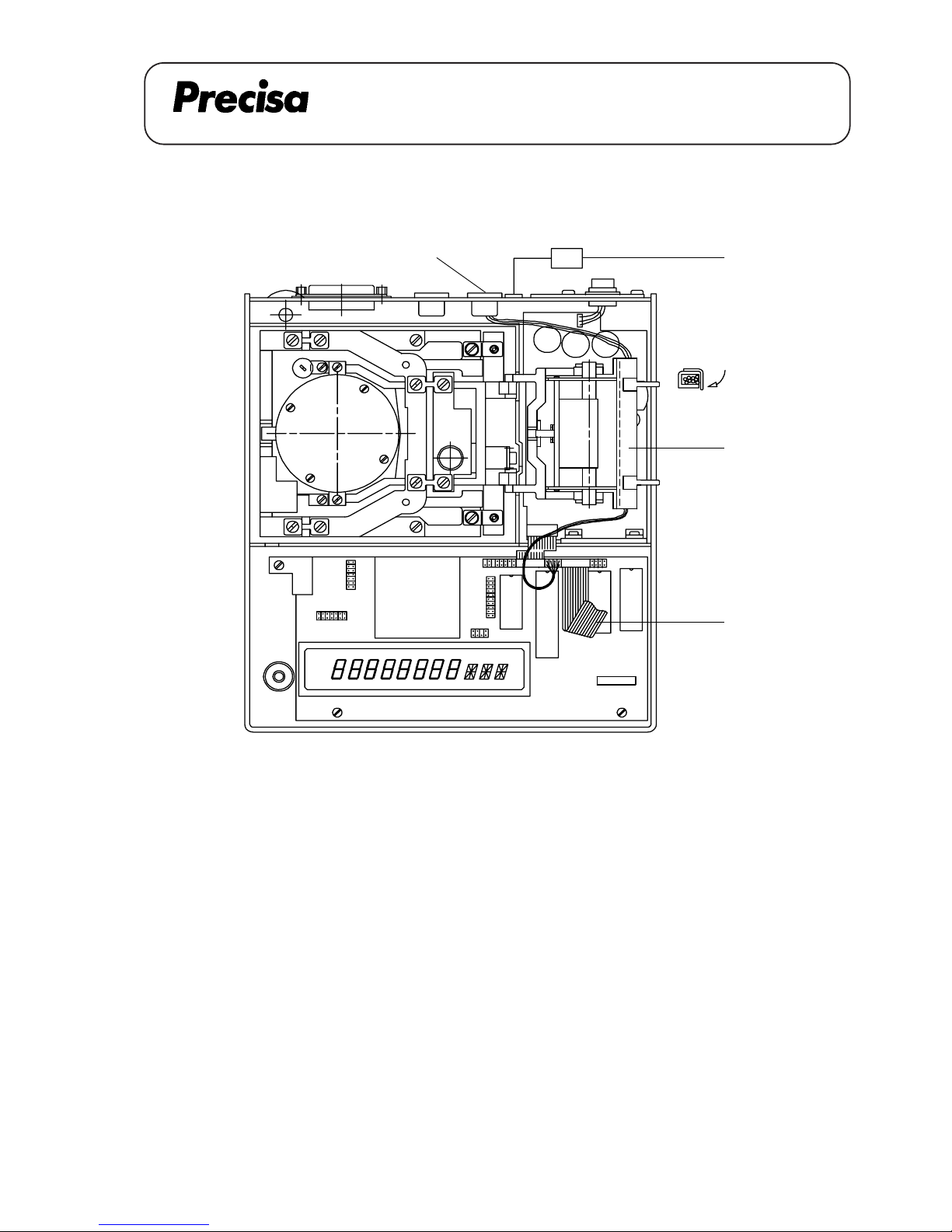
PAG OERLIKON AG
SERIES-300 SCS
INTERFACE HA 300 (350-8887)
Interface HA 300 350-8887
[4]
[3]
[A]
[1,2]
HA 300
[5]
Key No. Part No. Description
1 350-7159 Cable
2 PN 1100-011 Screw M3x6
3 350-8026 Cable channel
4 350-4047-007 Label
5 Clip (cable channel)
A 20.01
Page 61
PAG OERLIKON AG
SERIES-300 SCS
INTERFACE HA 300 (350-8887)
Assembly instruction for the data output HA 300
1. Lift the balance top, disconnect the flat wire [A] and remove the cover plate in the rear of the balance.
Fix the cable channel [3].
2. Insert the cable [1] through the opening and fix the plug with two screws [2].
3. Lead the cable [1] through the cable channel and connect it to the plug [B]. Bend the clip [5] 90°.
4. Reassemble the balance, connect the flat wire [A] and mount the label [4].
Montage-Anleitung des Datenausgangs für HA 300
1. Waagenoberteil abheben, Flachbandkabel [A] lösen und Datenausgang-Abdeckung auf Rückseite
der Waage entfernen. Kabelkanal [3] montieren.
2. Kabel [1] durch die Öffnung führen und den Stecker mit den zwei Schrauben [2] befestigen.
3. Kabel [1] durch den Kabelkanal durchführen und mit Stecker [B] verbinden. Klipp [5] 90°
umbieben.
4. Waage wieder zusammensetzen, Flachbandkabel [A] anschliessen und Schild [4] montieren.
Notice d'installation pour la sortie de donées HA 300
1. Soulever la partie supérieure de la balance, débrancher le câble plat [A] et retirer le couvercle de la
sortie de donées en arrière de la balance. Monter le caniveau électrique [3].
2. Passer le câble [1] à travers de l'ouverture et fixer la fiche avec deux vis [2].
3. Passer le câble [1] dans le caniveau électrique et le relier avec la fiche [B]. Plier le clip [5] 90°.
4. Remonter la balance, connecter la câble plat [A] et monter l'étiquette [4].
A 20.02
Page 62
PAG OERLIKON AG
SERIES-300 SIP
INTERFACE RS 232 / V24 (350-8838)
INTERFACE RS 232 / V24 (350-8838)
AA
D
9
J
L
A
B
C
E
F
GH B K
A - A
A 21.01
Page 63
PAG OERLIKON AG
SERIES-300 SIP
INTERFACE RS 232 / V24 (350-8838)
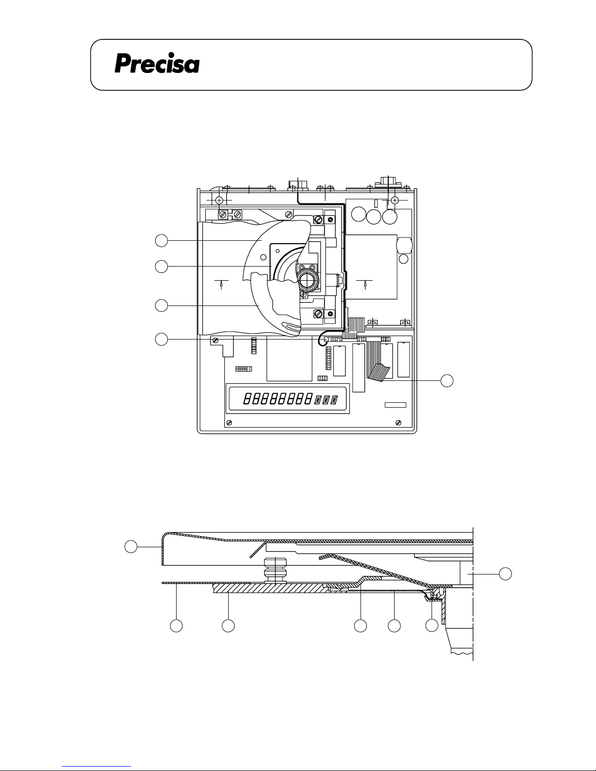
Dismantling the housing's top
1. Remove the weighing pan [F], lift carefully the pan holder [L]
2. Dismantle the retention ring [C], take off the cover plate [A]
3. Loose the 4 screws of the cover [B], take off the cover
4. Spread the locking ring [K] and remove it
5. Take off the membrane [J]
6. Dismantle the dust-cover [G], loose the screw of the housing's top
7. Lift the housing's top [H] a bit, disconnect the flat-wire [E]
8. Take off the housing's top
Mounting the housing's top
1. Connect the flat-wire [E] to the housing's top [H]
2. Mount carefully the housing's top on the balance, fasten the screw on the housing's top
3. Pull the dust-cover [G] over the balance
4. Insert the membrane [J], mount the locking ring [K]
5. Align the membrane [J] (without any stress and waves)
6. Place carefully the cover [B] (do not move it sidewards), fasten it with 4 screws
7. Mount the cover plate [A] and the retention ring [C]
8. Bring carefully the pan holder [L] in place, mount the weighing pan [F]
A 21.02
Page 64
PAG OERLIKON AG
SERIES-300 SIP
INTERFACE RS 232 / V24 (350-8838)
Demontage Gehäuseoberteil
1. Waagschale [F] abnehmen, Waagschalenträger [L] vorsichtig herausziehen
2. Haltering [C] demontieren, Deckblech [A] abnehmen
3. 4 Befestigungsschrauben der Abdeckung [B] lösen, Abdeckung entfernen
4. Klemmring [K] leicht spreizen und abheben
5. Membrane [J] entfernen
6. Schutzhaube [G] abheben, Sechskantschraube am Gehäuseoberteil lösen
7. Gehäuseoberteil [H] leicht anheben, Flachbandkabel [E] lösen
8. Gehäuseoberteil ganz entfernen
Montage Gehäuseoberteil
1. Flachbandkabel [E] am Gehäuseoberteil [H] anschliessen
2. Gehäuseoberteil sauber auf der Waage positionieren, Sechskantschraube anziehen
3. Staubschutzhülle [G] über die Waage legen
4. Membrane [J] einlegen, Klemmring [K] montieren
5. Membrane [J] ausrichten (spannungsfrei, ohne Wellen)
6. Abdeckung [B] vorsichtig aufsetzen (seitlich nicht verschieben), 4 Befestigungsschrauben anziehen
7. Deckblech [A] montieren, Haltering [C] montieren
8. Waagschalenträger [L] vorsichtig einfahren, Waagschale [F] aufsetzen
A 21.03
Page 65
PAG OERLIKON AG
SERIES-300 SIP
INTERFACE RS 232 / V24 (350-8838)
Demontage du boîtier supérieur
1. Enlever le plateau [F] et lever doucement le porte-plateau [L]
2. Démonter le dispositif de retenue [C] et la tôle de couvercle [A]
3. Dévisser les 4 vis de la tôle de retenue [B], démonter la tôle de retenue
4. Ecarter l'anneau de serrage [K] afin de l'enlever
5. Enlever la membrane [J]
6. Enlever la housse de protection [G], dévisser la vis du boîtier supérieur
7. Enlever le boîtier supérieur [H] un peu, débrancher le câble-plat [E]
8. Enlever le boîtier supérieur
Montage du boîtier supérieur
1. Brancher le câble-plat [E] avec le boîtier supérieur
2. Monter le boîtier supérieur doucement sur la balance, serrer la vis du boîtier supérieur
3. Monter la housse de protection [G]
4. Mettre la membrane [J] en place, monter l'anneau de serrage [K]
5. Aligner la membrane [J] (sans tension et sans onde)
6. Mettre avec précaution la tôle de retenue [B] en place (sans la déplacer latéralement) et la fixer avec les 4
vis
7. Monter la tôle de couvercle [A] et le dispositif de retenue [C]
8. Insérer doucement le porte-plateau [L] et monter le plateau [F]
A 21.04
Page 66
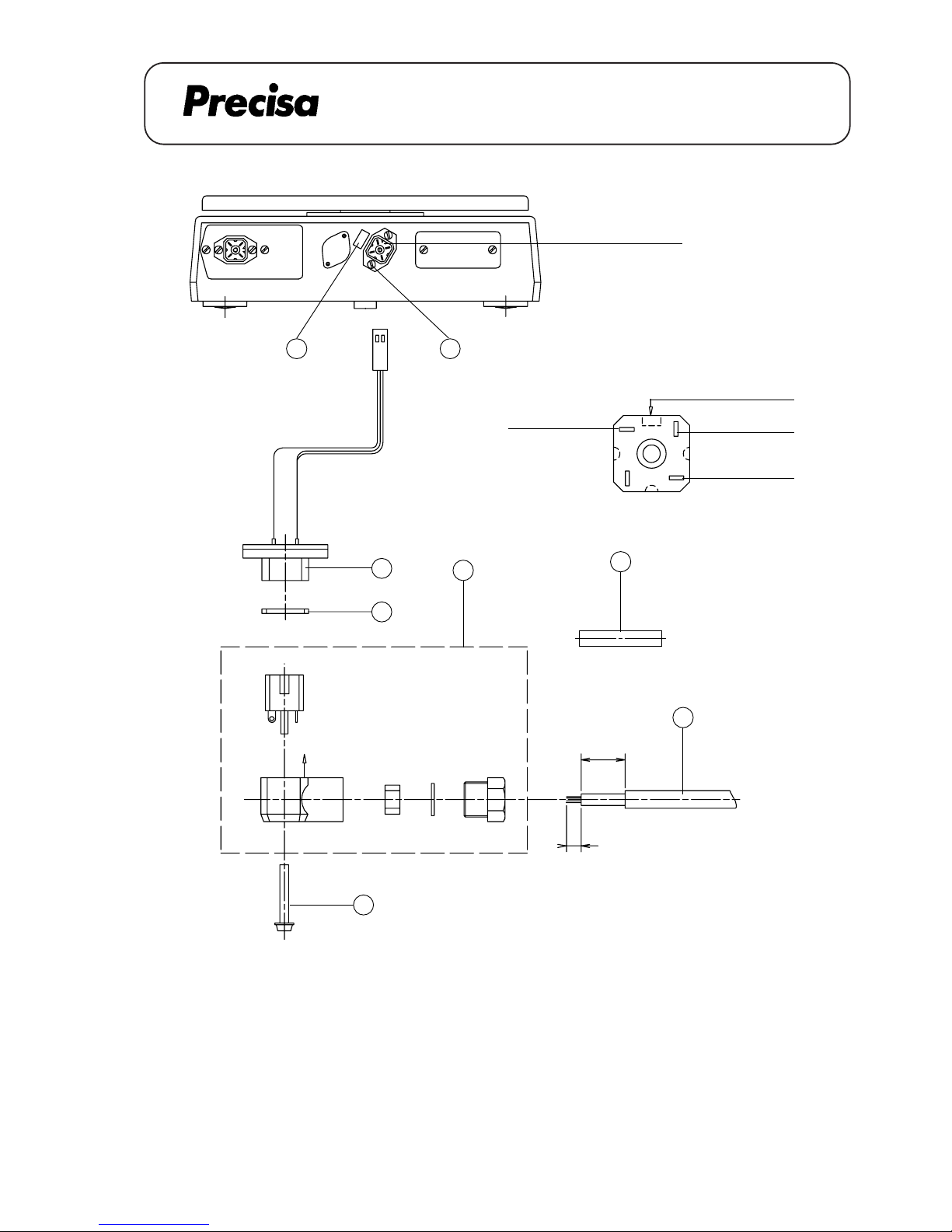
PAG OERLIKON AG
SERIES-300 SIP
INTERFACE RS 232 / V24 (350-8838)
Mind the code
strip the insulation for 5 mm
20
3
2
X
Diameter
5 ... 7 mm
For sealing the plug if
the cable is not connected
View X (Interconnection)
1
1.1
4
M
1.2
5
Key No. Part No. Description Beschriebung
1 350-8007 socket Buchse
1.1 sealing Dichtung
1.2 screw Schraube
2 PN 1100-062 screw M3x8 Schraube M3x8
3 PN 3602-200 plug Stecker
4 350-3036 trunnion Zapfen
5 350-4033-002 label Schild
2
3
413
RS 232 IN
CODE
RS 232 OUT
GND
A 21.05
Page 67
PAG OERLIKON AG
SERIES-300 SIP
INTERFACE RS 232 / V24 (350-8838)
Assembly instructions interface RS 232 / V 24
1. Dismantel the housing's top (see page 2)
2. Disassamble the oval cover-plate on the rear of the housing
3. Bring the cable in place and connect the plug [D] (on page 1)
4. Screw the socket [1] with two screws [2] (mind the code)
5. Assemble the plug [3] with the cable [M] (customer) according the connection diagram (mind the code)
By tightening the stuffing-box, you have to push the cable towards the plug to assure the closeness
6. Connect the plug [3] with the sealing [1.1] and the screw [1.2]
7. Stick the label [5]
8. Mount the housing's top (see page 2)
Montageanleitung Interface RS 232 / V 24
1. Demontage Gehäuseoberteil (siehe Seite 3)
2. Ovale Abdeckung auf der Gehäuse-Rückwand demontieren
3. Kabel verlegen und Stecker [D] (auf Seite 1) anschliessen
4. Buchse [1] mit Schrauben [2] befestigen (Codierung beachten)
5. Stecker [3] gemäss Schaltplan an Kabel [M] (kundenseitig) anschliessen
Beim Anziehen der Stopfbüchse das Kabel in Richtung Stecker stossen (Codierung beachten)
6. Stecker [3] mit Dichtung [1.1] und Schraube [1.2] montieren
7. Schild [5] ankleben
8. Montage Gehäuseoberteil (siehe Seite 3)
Notice de montage interface RS 232 / V 24
1. Démonter le boîtier supérieur (voir page 4)
2. Démonter la plaque ovale à l'arrière du boîtier
3. Mettre le câble en place et connecter la fiche [D] (à la page 1)
4. Monter la prise [1] avec les vis [2] (tenir compte au codage)
5. Assembler la prise [3] selon le schéma du couplage (tenir comte au codage)
En serrant la presse-étoupe, pousser le câble vers la prise pour assurer l'étanchéité
6. Monter la prise [3] avec le joint [1.1] et la vis [1.2]
7. Coller la plaque signalétique [5]
8. Monter le boîtier supérieur (voir page 4)
A 21.06
Page 68
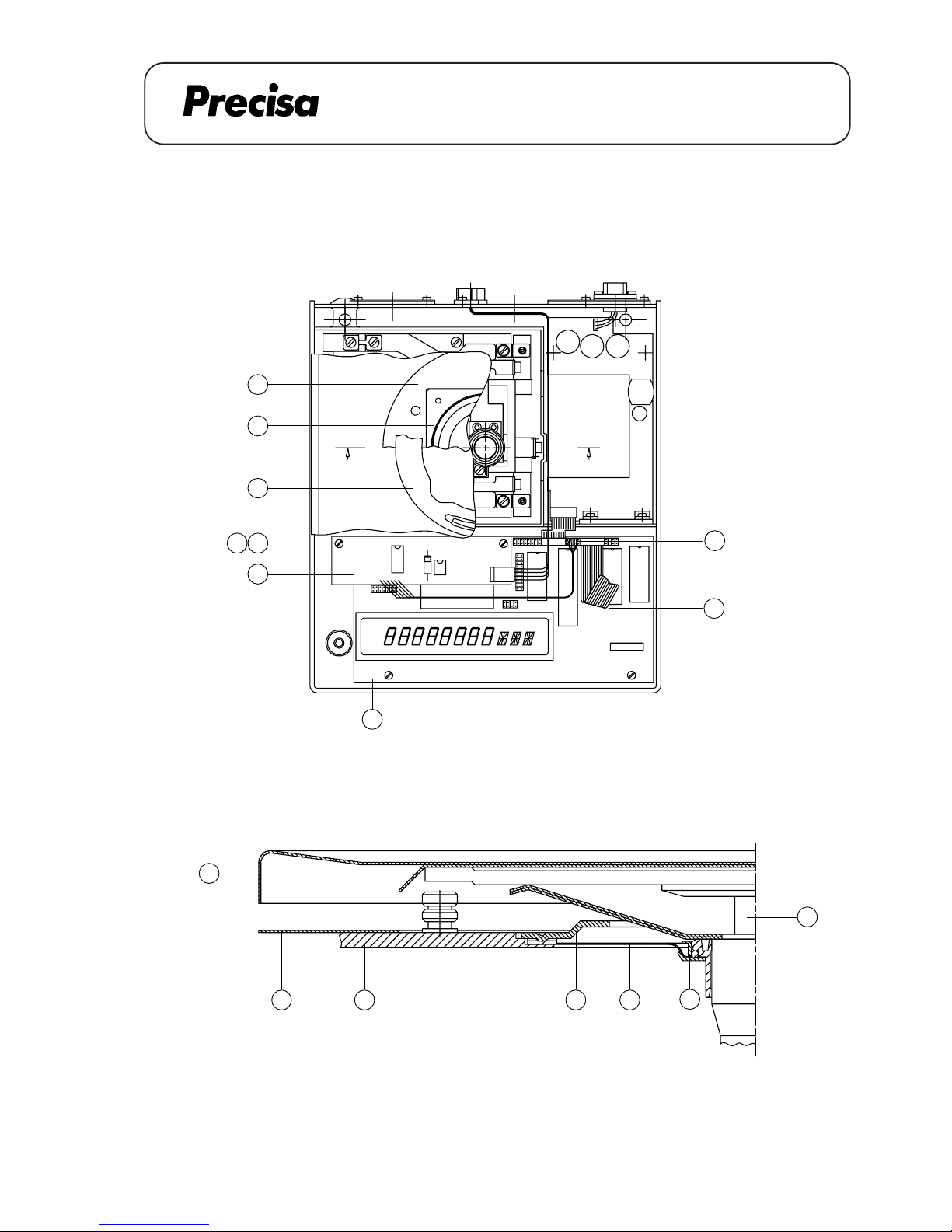
PAG OERLIKON AG
SERIAL-INTERFACE 20mA CL (350-8839)
SERIES-300 SIP
SERIAL INTERFACE 20mA CL (350-8839)
9
J
L
A
B
C
E
F
GH B K
A - A
AA
P
D
11
1312
A 22.01
Page 69
PAG OERLIKON AG
SERIAL-INTERFACE 20mA CL (350-8839)
SERIES-300 SIP
Dismantling the housing's top
1. Remove the weighing pan [F], lift carefully the pan holder [L]
2. Dismantle the retention ring [C], take off the cover plate [A]
3. Loose the 4 screws of the cover [B], take off the cover
4. Spread the locking ring [K] and remove it
5. Take off the membrane [J]
6. Dismantle the dust-cover [G], loose the screw of the housing's top
7. Lift the housing's top [H] a bit, disconnect the flat-wire [E]
8. Take off the housing's top
Mounting the housing's top
1. Connect the flat-wire [E] to the housing's top [H]
2. Mount carefully the housing's top on the balance, fasten the screw on the housing's top
3. Pull the dust-cover [G] over the balance
4. Insert the membrane [J], mount the locking ring [K]
5. Align the membrane [J] (without any stress and waves)
6. Place carefully the cover [B] (do not move it sidewards), fasten it with 4 screws
7. Mount the cover plate [A] and the retention ring [C]
8. Bring carefully the pan holder [L] in place, mount the weighing pan [F]
A 22.02
Page 70
PAG OERLIKON AG
SERIAL-INTERFACE 20mA CL (350-8839)
SERIES-300 SIP
Demontage Gehäuseoberteil
1. Waagschale [F] abnehmen, Waagschalenträger [L] vorsichtig herausziehen
2. Haltering [C] demontieren, Deckblech [A] abnehmen
3. 4 Befestigungsschrauben der Abdeckung [B] lösen, Abdeckung entfernen
4. Klemmring [K] leicht spreizen und abheben
5. Membrane [J] entfernen
6. Schutzhaube [G] abheben, Schraube am Gehäuseoberteil lösen
7. Gehäuseoberteil [H] leicht anheben, Flachbandkabel [E] lösen
8. Gehäuseoberteil ganz entfernen
Montage Gehäuseoberteil
1. Flachbandkabel [E] am Gehäuseoberteil [H] anschliessen
2. Gehäuseoberteil sauber auf der Waage positionieren, Schraube anziehen
3. Staubschutzhülle [G] über die Waage legen
4. Membrane [J] einlegen, Klemmring [K] montieren
5. Membrane [J] ausrichten (spannungsfrei, ohne Wellen)
6. Abdeckung [B] vorsichtig aufsetzen (seitlich nicht verschieben), 4 Befestigungsschrauben anziehen
7. Deckblech [A] montieren, Haltering [C] montieren
8. Waagschalenträger [L] vorsichtig einfahren, Waagschale [F] aufsetzen
A 22.03
Page 71
PAG OERLIKON AG
SERIAL-INTERFACE 20mA CL (350-8839)
SERIES-300 SIP
Demontage du boîtier supérieur
1. Enlever le plateau [F] et lever doucement le porte-plateau [L]
2. Démonter le dispositif de retenue [C] et la tôle de couvercle [A]
3. Dévisser les 4 vis de la tôle de retenue [B], démonter la tôle de retenue
4. Ecarter l'anneau de serrage [K] afin de l'enlever
5. Enlever la membrane [J]
6. Enlever la housse de protection [G], dévisser la vis du boîtier supérieur
7. Enlever le boîtier supérieur [H] un peu, débrancher le câble-plat [E]
8. Enlever le boîtier supérieur
Montage du boîtier supérieur
1. Brancher le câble-plat [E] avec le boîtier supérieur
2. Monter le boîtier supérieur doucement sur la balance, serrer la vis du boîtier supérieur
3. Monter la housse de protection [G]
4. Mettre la membrane [J] en place, monter l'anneau de serrage [K]
5. Aligner la membrane [J] (sans tension et sans onde)
6. Mettre avec précaution la tôle de retenue [B] en place (sans la déplacer latéralement) et la fixer avec les 4
vis
7. Monter la tôle de couvercle [A] et le dispositif de retenue [C]
8. Insérer doucement le porte-plateau [L] et monter le plateau [F]
A 22.04
Page 72
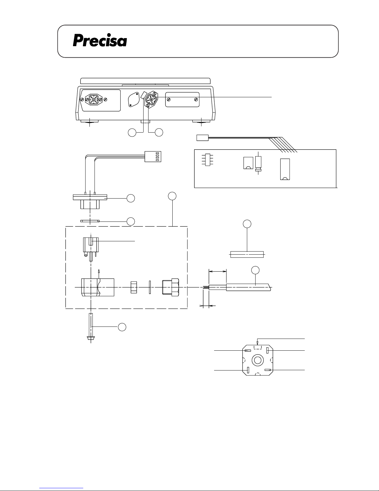
PAG OERLIKON AG
SERIAL-INTERFACE 20mA CL (350-8839)
SERIES-300 SIP
Mind the code
For sealing the plug if
the cable is not connected
4
Key No. Part No. Description Beschreibung
1 350-7084 socket Buchse
1.1 sealing Dichtung
1.2 screw Schraube
2 PN 1100-062 screw M3x8 Schraube M3x8
3 PN 3602-200 plug Stecker
4 350-3036 trunnion Zapfen
5 350-4033-001 label Schild
2
5
1
3
X
strip the insulation for 5 mm
Diameter
5 ... 7 mm
20
M
1.2
1.1
Mind the code
View X (Interconnection)
41
2
3
IN+
OUT-
IN-
OUT+
CODE
A 22.05
Page 73
PAG OERLIKON AG
SERIAL-INTERFACE 20mA CL (350-8839)
SERIES-300 SIP
Assembly instruction for analogue output
1. Dismantel the housing's top (see page 2)
2.Disassamble the oval cover-plate on the rear of the housing
3. Insert the cable [1] through the opening and fix the plug with two screws [2].
4. Fix the D/A-board [11] with two distance holders [12] on the main board [D] (with two screws [13]
from the main board).
5. Lead the cable [1] through the cable channel between the power supply and the crosswall from the
housing's bottom and connect it to the D/A-board [11].
6. Connect the cable [P].
7. Reassemble the balance, connect the flat wire [E] and mount the label [5].
Montage-Anleitung des Analogausgangs
1. Demontage Gehäuseoberteil (siehe Seite 3)
2.Ovale Abdeckung auf der Gehäuse-Rückwand demontieren.
3. Kabel [1] durch die Öffnung führen und den Stecker mit den zwei Schrauben [2] befestigen.
4. D/A-Wandlerprint [11] mit zwei Distanzhaltern [12] auf den Hauptprint [D] schrauben (mit
den Schrauben [13] vom Hauptprint).
5. Kabel [1] durch den Kabelkanal zwischen dem Netzteil-Print und der Gehäuse-Trennwand durchführen und mit dem D/A-Wandlerprint [11] verbinden.
6. Kabel [P] anschliessen.
7. Waage wieder zusammensetzen, Flachbandkabel [E] anschliessen und Schild [5] montieren.
A 22.06
Page 74
PAG OERLIKON AG
SERIAL-INTERFACE 20mA CL (350-8839)
SERIES-300 SIP
Notice de montage pour analog output
1. Démonter le boîtier supérieur ( voire page 4 )
2. Démonter la plaque ovale à l'arriére du boîtier.
3. Insérer le câble [1] à travers de l'ouverture et fixer la fiche avec deux vis [2].
4. Fixer la carte imprimée D/A [11] avec deux ports de distance [12] à la carte principale [D] (avec deux
vis [13] de la carte principale).
5. Mener le câble [1] à travers du caniveau électrique entre carte d'alimentation et la petite paroi de
séparation du boîtier intérieur et le brancher avec la carte imprimée D/A [11].
6. Brancher le câble [P].
7. Remonter la balance, connecter de nouveau le câble plat [E] et monter l'étiquette [5].
A 22.07
Page 75
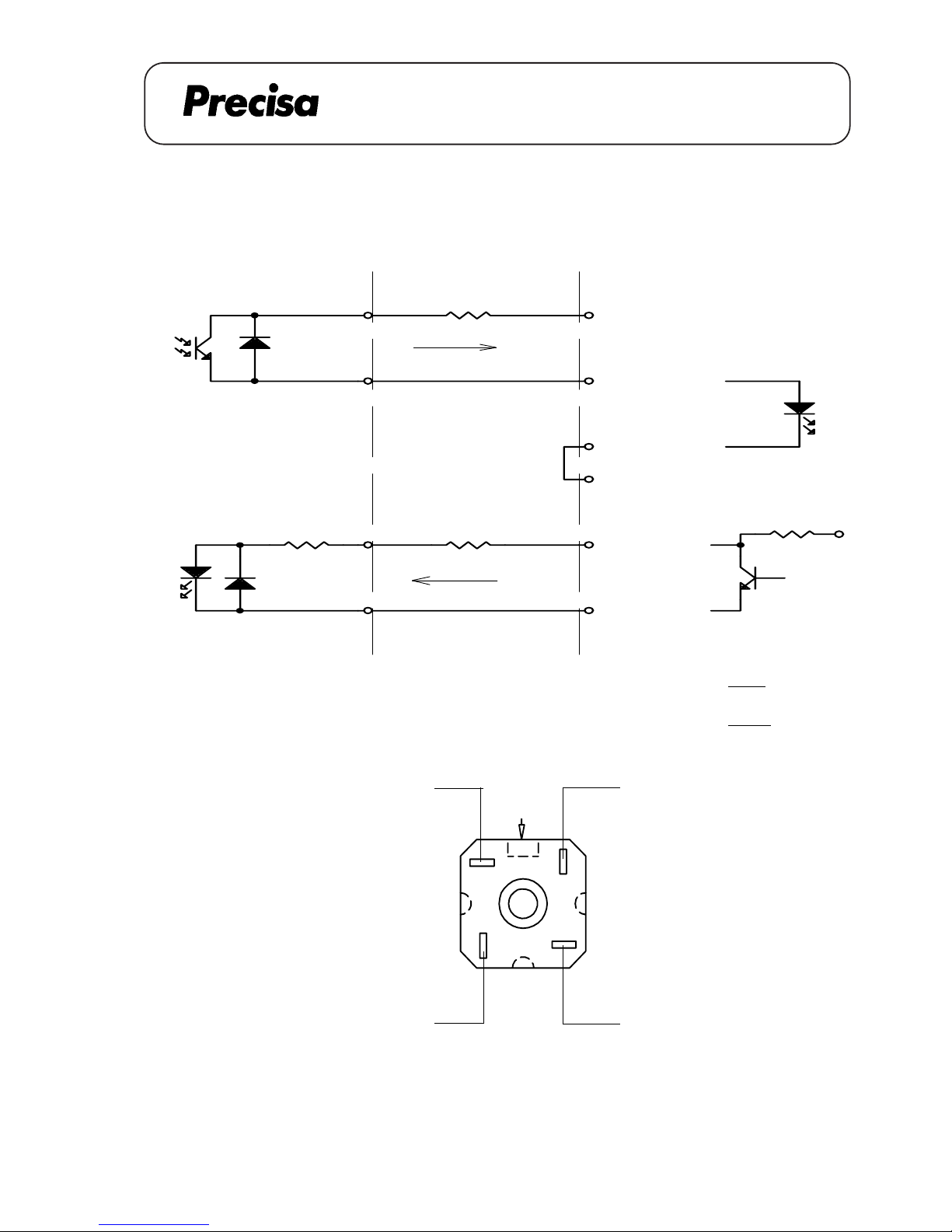
PAG OERLIKON AG
SERIAL-INTERFACE 20mA CL (350-8839)
SERIES-300 SIP
Rx
3
Data
+Ux
20mA in
Data out
GND
INTERCONNECTION BALANCE ----- DEVICE
Balance
47R
IF
Device
( printer,computer,etc. )
+Ux
20mA out
GND
Ry
1
4
2
R
Rx=
Ux - 2V
0.02
Ry =
Ux - 3V
0.02
- R
1
4
3
2
Code
Configurations and data transmissions see operating instructions series 300 section 11
Data
A 22.08
Page 76
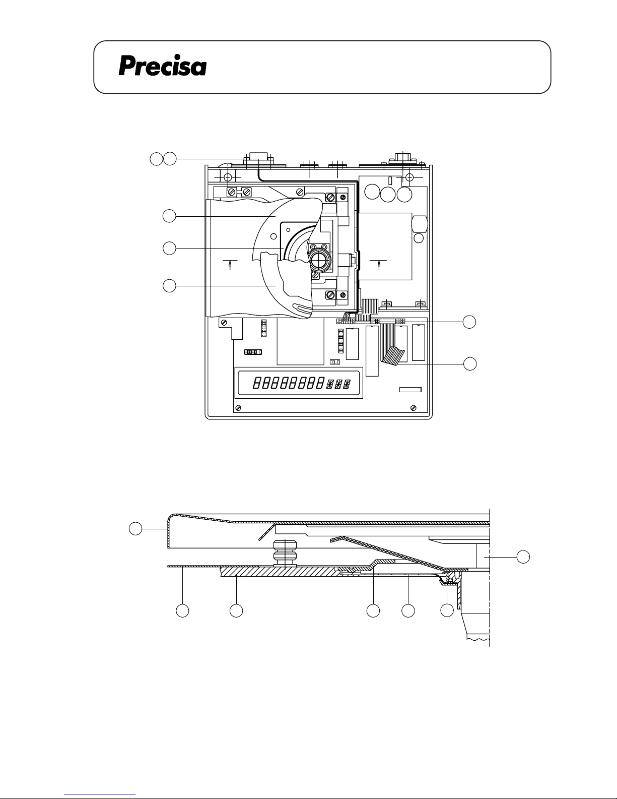
PAG OERLIKON AG
AP 11 (APPLICATION PACK) with IP 65 (350-8851)
SERIES-300 SIP
INSTALLATION INSTRUCTION FOR AP11 350-8851
9
J
L
F
GH B K
A - A
A
C
B
A
A
E
Key No. Part No. Description
1 350-8011 socket
2 PN 1100-062 screw M3 x 8
1
2
3
A 23.01
Page 77
PAG OERLIKON AG
AP 11 (APPLICATION PACK) with IP 65 (350-8851)
SERIES-300 SIP
Dismantling the housing's top
1. Remove the weighing pan [F], lift carefully the pan holder [L]
2. Dismantle the retention ring [C], take off the cover plate [A]
3. Loose the 4 screws of the cover [B], take off the cover
4. Spread the locking ring [K] and remove it
5. Take off the membrane [J]
6. Dismantle the dust-cover [G], loose the screw of the housing's top
7. Lift the housing's top [H] a bit, disconnect the flat-wire [E]
8. Take off the housing's top
Mounting the housing's top
1. Connect the flat-wire [E] to the housing's top [H]
2. Mount carefully the housing's top on the balance, fasten the screw on the housing's top
3. Pull the dust-cover [G] over the balance
4. Insert the membrane [J], mount the locking ring [K]
5. Align the membrane [J] (without any stress and waves)
6. Place carefully the cover [B] (do not move it sidewards), fasten it with 4 screws
7. Mount the cover plate [A] and the retention ring [C]
8. Bring carefully the pan holder [L] in place, mount the weighing pan [F]
A 23.02
Page 78
PAG OERLIKON AG
AP 11 (APPLICATION PACK) with IP 65 (350-8851)
SERIES-300 SIP
Demontage Gehäuseoberteil
1. Waagschale [F] abnehmen, Waagschalenträger [L] vorsichtig herausziehen
2. Haltering [C] demontieren, Deckblech [A] abnehmen
3. 4 Befestigungsschrauben der Abdeckung [B] lösen, Abdeckung entfernen
4. Klemmring [K] leicht spreizen und abheben
5. Membrane [J] entfernen
6. Schutzhaube [G] abheben, Schraube am Gehäuseoberteil lösen
7. Gehäuseoberteil [H] leicht anheben, Flachbandkabel [E] lösen
8. Gehäuseoberteil ganz entfernen
Montage Gehäuseoberteil
1. Flachbandkabel [E] am Gehäuseoberteil [H] anschliessen
2. Gehäuseoberteil sauber auf der Waage positionieren, Schraube anziehen
3. Staubschutzhülle [G] über die Waage legen
4. Membrane [J] einlegen, Klemmring [K] montieren
5. Membrane [J] ausrichten (spannungsfrei, ohne Wellen)
6. Abdeckung [B] vorsichtig aufsetzen (seitlich nicht verschieben), 4 Befestigungsschrauben anziehen
7. Deckblech [A] montieren, Haltering [C] montieren
8. Waagschalenträger [L] vorsichtig einfahren, Waagschale [F] aufsetzen
A 23.03
Page 79
PAG OERLIKON AG
AP 11 (APPLICATION PACK) with IP 65 (350-8851)
SERIES-300 SIP
Demontage du boîtier supérieur
1. Enlever le plateau [F] et lever doucement le porte-plateau [L]
2. Démonter le dispositif de retenue [C] et la tôle de couvercle [A]
3. Dévisser les 4 vis de la tôle de retenue [B], démonter la tôle de retenue
4. Ecarter l'anneau de serrage [K] afin de l'enlever
5. Enlever la membrane [J]
6. Enlever la housse de protection [G], dévisser la vis du boîtier supérieur
7. Enlever le boîtier supérieur [H] un peu, débrancher le câble-plat [E]
8. Enlever le boîtier supérieur
Montage du boîtier supérieur
1. Brancher le câble-plat [E] avec le boîtier supérieur
2. Monter le boîtier supérieur doucement sur la balance, serrer la vis du boîtier supérieur
3. Monter la housse de protection [G]
4. Mettre la membrane [J] en place, monter l'anneau de serrage [K]
5. Aligner la membrane [J] (sans tension et sans onde)
6. Mettre avec précaution la tôle de retenue [B] en place (sans la déplacer latéralement) et la fixer avec les 4
vis
7. Monter la tôle de couvercle [A] et le dispositif de retenue [C]
8. Insérer doucement le porte-plateau [L] et monter le plateau [F]
A 23.04
Page 80
PAG OERLIKON AG
AP 11 (APPLICATION PACK) with IP 65 (350-8851)
SERIES-300 SIP
Installation instruction for AP11 with IP 65
1. Dismantel the housing´s top (see page 2)
2. Dismantel the cover plate on the back of the balance.
3. Bring the cable into place accoroding to the drawing and connect plug [3] to the socket.
4. Fix the socket [1] with the two scews [2]
6. Reassemble the balance and connect the flat wire [E].
Montage - Anleitung AP11 mit IP 65
1. Demontage Gehäuseoberteil ( siehe Seite 3)
2. Die Abdeckung an der Rückseite der Waage demontieren.
3. Das Kabel gemäss Zeichnung verlegen und Stecker [3] anschliessen.
4. Die Buchse [1] mit den zwei Schrauben [2] befestigen.
5. Waage wieder zusammensetzen und Flachbandkabel [E] anschliessen.
Notice d’installation AP11 avec IP 65
1. Démonter le boîtier supérieur ( voir page 4)
2. Demonter la plaque en arrière de la balance.
3. Mettre le câble en place selon le dessin et connecteur la fiche [3] à la prise.
4. Fixer la prise [1] avec les deux vis [2]
5. Remonter la balance et connecter de nouveau le câble plat [E].
A 23.05
Page 81
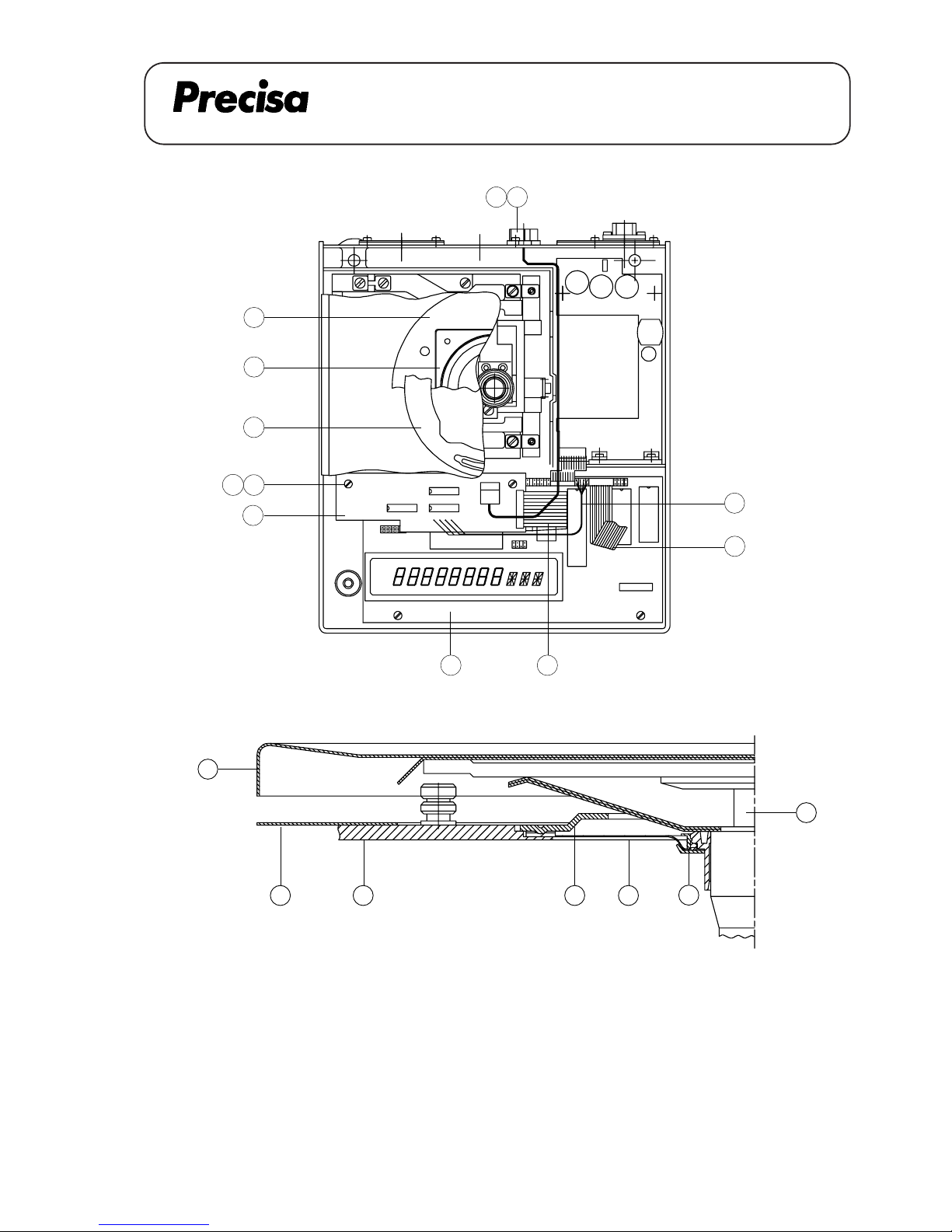
PAG OERLIKON AG
SERIES-300 SIP
ANALOGUE OUTPUT (350-8858)
ANALOGUE OUTPUT 350-8858
9
J
L
F
G
H
BK
A - A
D
C
B
A
1312
11
2
P
N
E
1
A 24.01
Page 82
PAG OERLIKON AG
SERIES-300 SIP
ANALOGUE OUTPUT (350-8858)
Dismantling the housing's top
1. Remove the weighing pan [F], lift carefully the pan holder [L]
2. Dismantle the retention ring [C], take off the cover plate [A]
3. Loose the 4 screws of the cover [B], take off the cover
4. Spread the locking ring [K] and remove it
5. Take off the membrane [J]
6. Dismantle the dust-cover [G], loose the screw of the housing's top
7. Lift the housing's top [H] a bit, disconnect the flat-wire [E]
8. Take off the housing's top
Mounting the housing's top
1. Connect the flat-wire [E] to the housing's top [H]
2. Mount carefully the housing's top on the balance, fasten the screw on the housing's top
3. Pull the dust-cover [G] over the balance
4. Insert the membrane [J], mount the locking ring [K]
5. Align the membrane [J] (without any stress and waves)
6. Place carefully the cover [B] (do not move it sidewards), fasten it with 4 screws
7. Mount the cover plate [A] and the retention ring [C]
8. Bring carefully the pan holder [L] in place, mount the weighing pan [F]
A 24.02
Page 83
PAG OERLIKON AG
SERIES-300 SIP
ANALOGUE OUTPUT (350-8858)
Demontage Gehäuseoberteil
1. Waagschale [F] abnehmen, Waagschalenträger [L] vorsichtig herausziehen
2. Haltering [C] demontieren, Deckblech [A] abnehmen
3. 4 Befestigungsschrauben der Abdeckung [B] lösen, Abdeckung entfernen
4. Klemmring [K] leicht spreizen und abheben
5. Membrane [J] entfernen
6. Schutzhaube [G] abheben, Schraube am Gehäuseoberteil lösen
7. Gehäuseoberteil [H] leicht anheben, Flachbandkabel [E] lösen
8. Gehäuseoberteil ganz entfernen
Montage Gehäuseoberteil
1. Flachbandkabel [E] am Gehäuseoberteil [H] anschliessen
2. Gehäuseoberteil sauber auf der Waage positionieren, Schraube anziehen
3. Staubschutzhülle [G] über die Waage legen
4. Membrane [J] einlegen, Klemmring [K] montieren
5. Membrane [J] ausrichten (spannungsfrei, ohne Wellen)
6. Abdeckung [B] vorsichtig aufsetzen (seitlich nicht verschieben), 4 Befestigungsschrauben anziehen
7. Deckblech [A] montieren, Haltering [C] montieren
8. Waagschalenträger [L] vorsichtig einfahren, Waagschale [F] aufsetzen
A 24.03
Page 84
PAG OERLIKON AG
SERIES-300 SIP
ANALOGUE OUTPUT (350-8858)
Demontage du boîtier supérieur
1. Enlever le plateau [F] et lever doucement le porte-plateau [L]
2. Démonter le dispositif de retenue [C] et la tôle de couvercle [A]
3. Dévisser les 4 vis de la tôle de retenue [B], démonter la tôle de retenue
4. Ecarter l'anneau de serrage [K] afin de l'enlever
5. Enlever la membrane [J]
6. Enlever la housse de protection [G], dévisser la vis du boîtier supérieur
7. Enlever le boîtier supérieur [H] un peu, débrancher le câble-plat [E]
8. Enlever le boîtier supérieur
Montage du boîtier supérieur
1. Brancher le câble-plat [E] avec le boîtier supérieur
2. Monter le boîtier supérieur doucement sur la balance, serrer la vis du boîtier supérieur
3. Monter la housse de protection [G]
4. Mettre la membrane [J] en place, monter l'anneau de serrage [K]
5. Aligner la membrane [J] (sans tension et sans onde)
6. Mettre avec précaution la tôle de retenue [B] en place (sans la déplacer latéralement) et la fixer avec les 4
vis
7. Monter la tôle de couvercle [A] et le dispositif de retenue [C]
8. Insérer doucement le porte-plateau [L] et monter le plateau [F]
A 24.04
Page 85
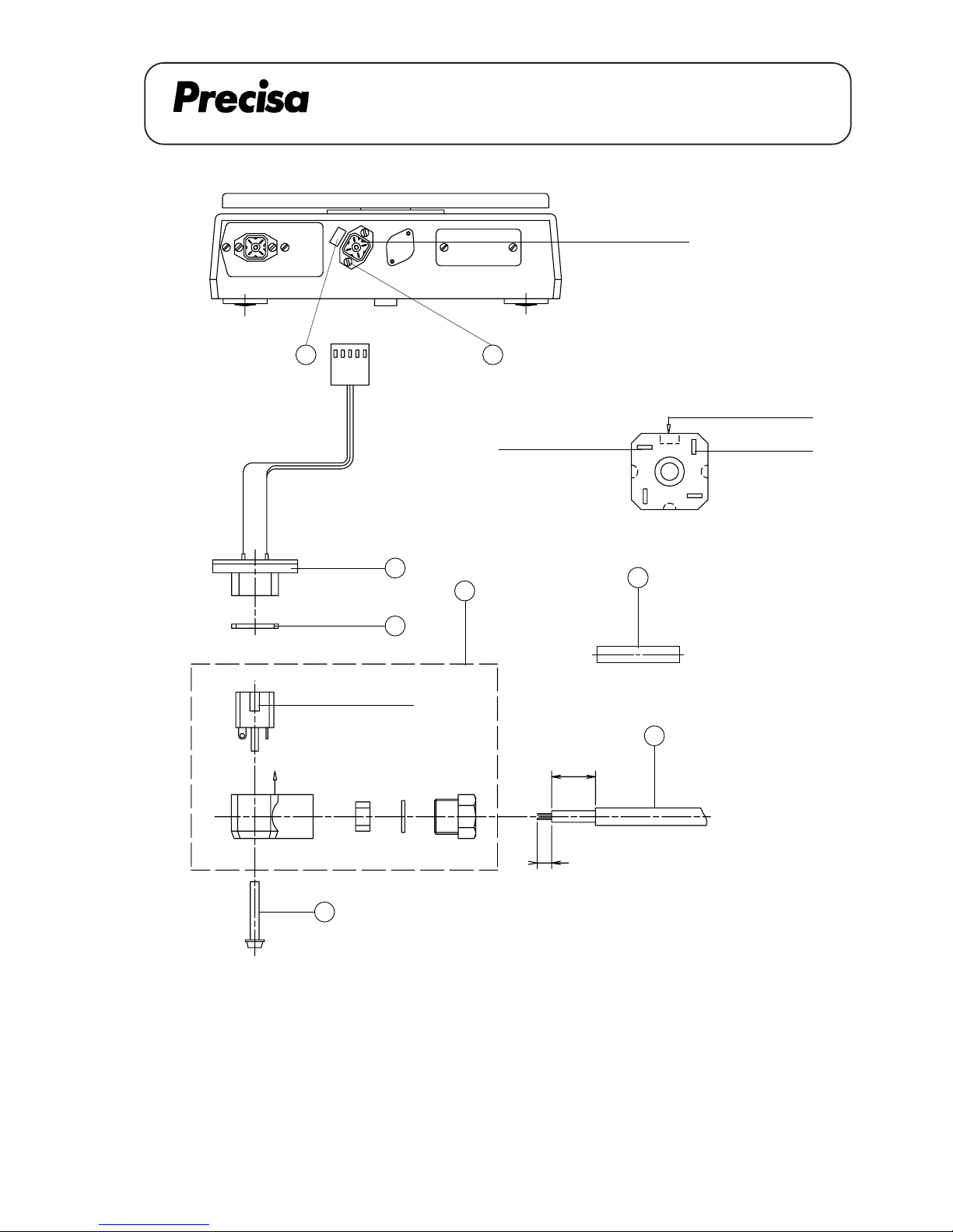
PAG OERLIKON AG
SERIES-300 SIP
ANALOGUE OUTPUT (350-8858)
View X (Interconnection)
2
3
41
CODE
GND
For sealing the plug if
the cable is not connected
4
Mind the code
strip the insulation for 5mm
Diameter
5...7mm
20
X
Mind the code
1.1
3
2
ANALOGUE OUT
1
5
M
1.2
Key No. Part No. Description Beschriebung
1 350-7115 socket Buchse
1.1 sealing Dichtung
1.2 screw Schraube
2 PN 1100-062 screw M3x8 Schraube M3x8
3 PN 3602-200 plug Stecker
4 350-3036 trunnion Zapfen
5 350-4033-002 label Schild
A 24.05
Page 86
PAG OERLIKON AG
SERIES-300 SIP
ANALOGUE OUTPUT (350-8858)
Montage-Anleitung des Analogausgangs
1. Demontage Gehäuseoberteil (siehe Seite 3)
2.Ovale Abdeckung auf der Gehäuse-Rückwand demontieren.
3. Kabel [1] durch die Öffnung führen und den Stecker mit den zwei Schrauben [2] befestigen.
4. D/A-Wandlerprint [11] mit zwei Distanzhaltern [12] auf den Hauptprint [D] schrauben (mit
den Schrauben [13] vom Hauptprint).
5. Flachbandkabel [N] am Hauptprint [D] anschliessen.
6. Kabel [1] durch den Kabelkanal zwischen dem Trafo und der Gehäuse-Trennwand durchführen und mit
dem D/A-Wandlerprint [11] verbinden.
7. Kabel [P] anschliessen.
8. Waage wieder zusammensetzen, Flachbandkabel [E] anschliessen und Schild [5] montieren.
Assembly instruction for analogue output
1. Dismantel the housing's top (see page 2)
2.Disassamble the oval cover-plate on the rear of the housing
3. Insert the cable [1] through the opening and fix the plug with two screws [2].
4. Fix the D/A-board [11] with two distance holders [12] on the main board [D] (with two screws [12] from
the main board).
5. Connect the flat wire [N] on the main board [D].
6. Lead the cable [1] through the cable channel between the transformer and the crosswall from the
housing's bottom and connect it to the D/A-board [11].
7. Connect the cable [P].
8. Reassemble the balance, connect the flat wire [E] and mount the label [5].
A 24.06
Page 87
PAG OERLIKON AG
SERIES-300 SIP
ANALOGUE OUTPUT (350-8858)
Notice de montage pour analog output
1. Démonter le boîtier supérieur ( voire page 4 )
2. Démonter la plaque ovale à l'arriére du boîtier.
3. Insérer le câble [1] à travers de l'ouverture et fixer la fiche avec deux vis [2].
4. Fixer la carte imprimée D/A [11] avec deux ports de distance [12] à la carte principale [D] (avec deux vis
[13] de la carte principale).
5. Brancher le câble plat [N] à la carte principale [D].
6. Mener le câble [1] à travers du caniveau électrique entre le transformateur et la petite paroi de séparation
du boîtier intérieur et le brancher avec la carte imprimée D/A [11].
7. Brancher le câble [P].
8. Remonter la balance, connecter de nouveau le câble plat [E] et monter l'étiquette [5].
A 24.07
Page 88
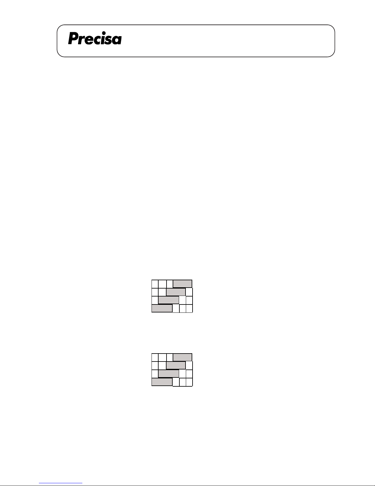
PAG OERLIKON AG
SERIES-300 SIP
ANALOGUE OUTPUT (350-8858)
A N A L O G U E - O U T P U T
DIN Plug : GND -> Pin 2 IP 65 : GND -> 4
OUT -> Pin 6 OUT -> 1
Settings: - The analogue output can be defined at the end of the main menu.
It is possible to choose up to 6 different settings
Settings: - Hi-Speed -> Scale from 0 until max. 6.4 V. velocity 20 ms
- Lo-Speed 1 -> Digit 0 - 1 - 2 and signs are converted at +/- 9.99 V.,
velocity 80 ms, 160 ms or 320 ms.
- Lo-Speed 2 -> Digit 1 - 2 - 3 and signs are converted at
+/- 9.99 V., velocity 80 ms, 160 ms or 320 ms
- Lo-Speed 3 -> Digit 2 - 3 - 4 and signs are converted at
+/- 9.99 V, velocity 80 ms, 160 ms or 320 ms
- Lo-Speed 4 -> Digit 3 - 4 - 5 and signs are converted at
+/- 9.99 V., velocity 80 ms, 160 ms or 320 ms
- Lo-Speed 5 -> Scale from 0 until 10 V. velocity 80ms, 160 ms or 320 ms
Examples: ( 3'100 C )
Display 1234,5 6 g
Lo-speed 1 1234,5 6 g -> 4.56 V
Lo-speed 2 1234,5 6 g -> 3.45 V
Lo-speed 3 1234,5 6 g -> 2.34 V
Lo-speed 4 1 2 3 4, 5 6 g -> 1.23 V
Hi-Speed 1234,5 6 g -> appr.4.40 V
( 10’200 G )
Display 1 0 4 5 6 g
Lo-speed 1 1 0 4 5 6 g -> 4.56 V
Lo-speed 2 1 0 4 5 6 g -> 0.45 V
Lo-speed 3 1 0 4 5 6 g -> 1.04 V
Lo-speed 4 1 0 4 5 6 g -> 0.10 V
Hi-Speed 1 0 4 5 6 g -> appr. 4.90 V
A 24.08
Page 89
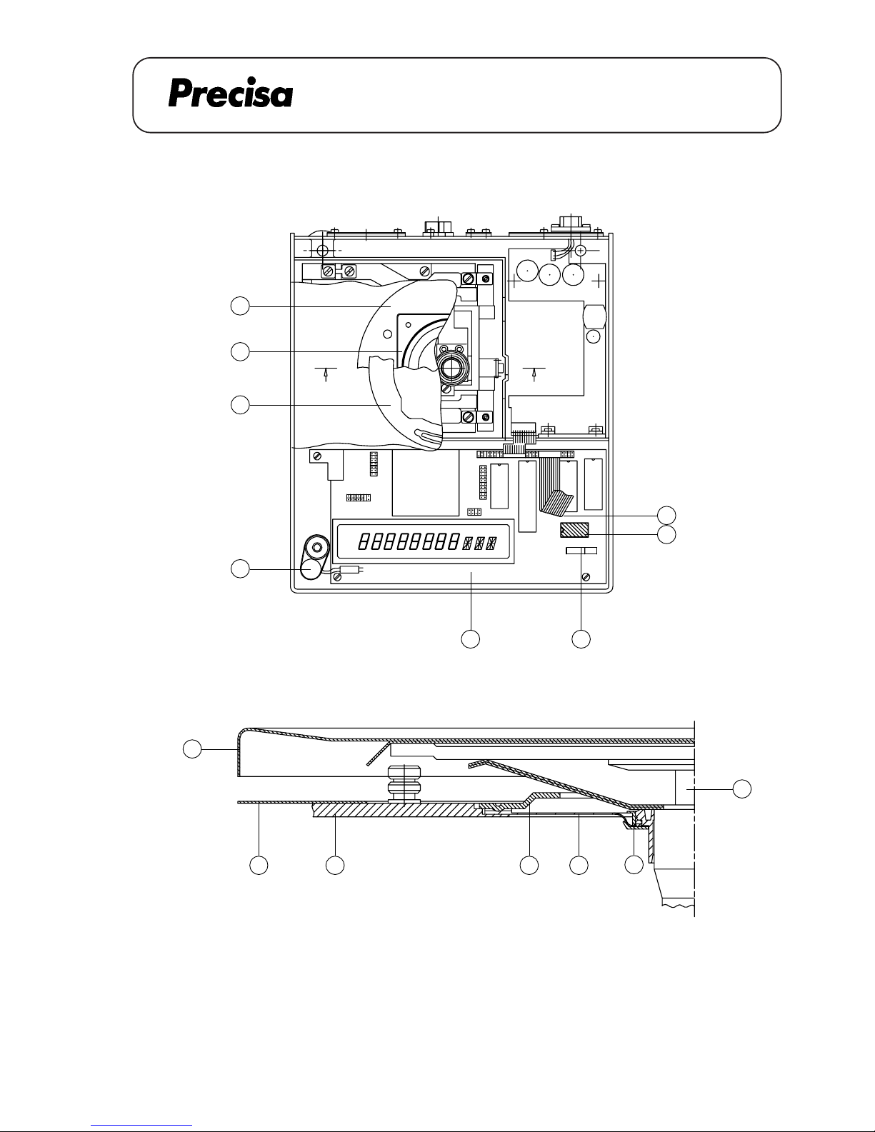
PAG OERLIKON AG
SERIES-300 SIP
CLOCK (350-8888)
INSTALLATION INSTRUCTION FOR OPTION CLOCK 350-8888
9
J
L
F
GH B K
A - A
A
C
B
A
A
M
E
1
D
2
Key No. Part No. Description
1 300-7060 NiCd-Accumulator
2 PN 3022-046 IC-RTC 72421 A
A 25.01
Page 90
PAG OERLIKON AG
SERIES-300 SIP
CLOCK (350-8888)
Dismantling the housing's top
1. Remove the weighing pan [F], lift carefully the pan holder [L]
2. Dismantle the retention ring [C], take off the cover plate [A]
3. Loose the 4 screws of the cover [B], take off the cover
4. Spread the locking ring [K] and remove it
5. Take off the membrane [J]
6. Dismantle the dust-cover [G], loose the screw of the housing's top
7. Lift the housing's top [H] a bit, disconnect the flat-wire [D]
8. Take off the housing's top
Mounting the housing's top
1. Connect the flat-wire [D] to the housing's top [H]
2. Mount carefully the housing's top on the balance, fasten the screw on the housing's top
3. Pull the dust-cover [G] over the balance
4. Insert the membrane [J], mount the locking ring [K]
5. Align the membrane [J] (without any stress and waves)
6. Place carefully the cover [B] (do not move it sidewards), fasten it with 4 screws
7. Mount the cover plate [A] and the retention ring [C]
8. Bring carefully the pan holder [L] in place, mount the weighing pan [F]
A 25.02
Page 91
PAG OERLIKON AG
SERIES-300 SIP
CLOCK (350-8888)
Demontage Gehäuseoberteil
1. Waagschale [F] abnehmen, Waagschalenträger [L] vorsichtig herausziehen
2. Haltering [C] demontieren, Deckblech [A] abnehmen
3. 4 Befestigungsschrauben der Abdeckung [B] lösen, Abdeckung entfernen
4. Klemmring [K] leicht spreizen und abheben
5. Membrane [J] entfernen
6. Schutzhaube [G] abheben, Schraube am Gehäuseoberteil lösen
7. Gehäuseoberteil [H] leicht anheben, Flachbandkabel [D] lösen
8. Gehäuseoberteil ganz entfernen
Montage Gehäuseoberteil
1. Flachbandkabel [D] am Gehäuseoberteil [H] anschliessen
2. Gehäuseoberteil sauber auf der Waage positionieren, Schraube anziehen
3. Staubschutzhülle [G] über die Waage legen
4. Membrane [J] einlegen, Klemmring [K] montieren
5. Membrane [J] ausrichten (spannungsfrei, ohne Wellen)
6. Abdeckung [B] vorsichtig aufsetzen (seitlich nicht verschieben), 4 Befestigungsschrauben anziehen
7. Deckblech [A] montieren, Haltering [C] montieren
8. Waagschalenträger [L] vorsichtig einfahren, Waagschale [F] aufsetzen
A 25.03
Page 92
PAG OERLIKON AG
SERIES-300 SIP
CLOCK (350-8888)
Demontage du boîtier supérieur
1. Enlever le plateau [F] et lever doucement le porte-plateau [L]
2. Démonter le dispositif de retenue [C] et la tôle de couvercle [A]
3. Dévisser les 4 vis de la tôle de retenue [B], démonter la tôle de retenue
4. Ecarter l'anneau de serrage [K] afin de l'enlever
5. Enlever la membrane [J]
6. Enlever la housse de protection [G], dévisser la vis du boîtier supérieur
7. Enlever le boîtier supérieur [H] un peu, débrancher le câble-plat [D]
8. Enlever le boîtier supérieur
Montage du boîtier supérieur
1. Brancher le câble-plat [D] avec le boîtier supérieur
2. Monter le boîtier supérieur doucement sur la balance, serrer la vis du boîtier supérieur
3. Monter la housse de protection [G]
4. Mettre la membrane [J] en place, monter l'anneau de serrage [K]
5. Aligner la membrane [J] (sans tension et sans onde)
6. Mettre avec précaution la tôle de retenue [B] en place (sans la déplacer latéralement) et la fixer avec les 4
vis
7. Monter la tôle de couvercle [A] et le dispositif de retenue [C]
8. Insérer doucement le porte-plateau [L] et monter le plateau [F]
A 25.04
Page 93
PAG OERLIKON AG
SERIES-300 SIP
CLOCK (350-8888)
Installation instruction for clock
1. Dismantel the housing´s top (see page 2)
2. Fix the accumulator [1] with the adhesive tape on the housing’s bottom.
3. Connect the plug of the accumulator on the main board [E].
4. Mount the clock-IC [2] (take care of the mark).
5. Switch the DIL-Switch [M] no.5 to the position ON.
6. Reassemble the balance and connect the flat wire [D].
Einbauanleitung für Uhrenset
1. Demontage Gehäuseoberteil ( siehe Seite 3)
2. Akku [1] mit doppelseitigem Klebband an Gehäuse-Unterteil befestigen.
3. Stecker des Akkus am Hauptprint [E] anschliessen.
4. Uhrenbaustein [2] montieren (Markierung beachten).
5. DIL-Switch [M] Nr.5 auf Position ON stellen.
6. Waage wieder zusammensetzen und Flachbandkabel [D] anschliessen.
Notice d’installation pour le set de la montre
1. Démonter le boîtier supérieur ( voir page 4)
2. Monter l’accu [1] avec la bande adhésive sur le bas du boîtier.
3. Connecter la fiche avec la carte principale [E].
4. Monter le CI de la montre [2] (respecter le marquage).
5. Mener le DIL-Switch [M] no.5 à la position ON.
5. Remonter la balance et connecter de nouveau le câble plat [D].
A 25.05
Page 94
SERIES-300 S / SCS / SIP
PAG OERLIKON AG
USERS INSTRUCTIONS
GEBRAUCHSANLEITUNG
B 01.01
How to order spare parts
In order to facilitate the searching of spare parts, this chapter is reorganisazed in groups.
The following chart shows, to which group the balance belongs, regarding the serie, the order number and the
model type.
Example: Series 300 S
Order no. 300-9405
Modell 620C
Group C1
On all subordinated representations, the desired spare part is to find in group C1.
Bestell-Nr.
300-9204
300-9206
300-9236
300-9233
300-9327
300-9319
300-9321
300-9322
300-9328
300-9329
300-9404
300-9405
300-9465
300-9475
300-9476
300-9466
300-9467
300-9480
300-9481
300-9473
300-9533
300-9534
300-9535
300-9502
300-9503
300-9290
300-9291
300-9292
300-9293
300-9294
300-9295
Modell
62A
125A
205A
185AM-FR
160M
210M
310M
361MC-FR
404M
610MC-FR
310C
620C
1620C
2200 CE
2600C
3100C
3610CD-FR
4200C
6200C
6100CD-FR
1620D
3100D
6200D
8200D
10200G
303M Carat
404M Carat
606M Carat
625MC-FR Carat
1050MC-FR Carat
3030C Carat
Gruppe
A1
A1
A2
A2
M1
M1
M1
M1
M1
M1
C1
C1
C2
C2
C3
C3
C3
C3
C3
C3
D1
D1
D1
D2
D2
A1
A1
A1
A1
A2
M1
Bestell-Nr.
300-9205
300-9234
300-9235
300-9323
300-9318
300-9324
300-9325
300-9326
300-9362
300-9363
300-9364
300-9406
300-9478
300-9468
300-9477
300-9469
300-9471
300-9470
300-9472
300-9536
300-9504
300-9505
300-9506
Modell
125A
205A
205AM-FR
220M
310M
404M
481MC-FR
610MC-FR
808M
1212M
505M-2020C
620C
820C
2200C
3100C
4200C
4810CD-FR
6200C
6100CD-FR
6200D
8200D
12400DG-FR
12100G
Gruppe
A1
A2
A2
M1
M1
M1
M1
M1
M2
M2
M2
C1
C2
C2
C3
C3
C3
C3
C3
D1
D2
D2
D2
Serie 300 S Serie 300 SCS
Order no.
300-9479
300-9540
300-9507
300-9508
Model
3100C
3100D
8200D
10200G
Group
C3
C3
D2
D2
Serie 300 SIP
Page 95
SERIES-300 S / SCS / SIP
PAG OERLIKON AG
USERS INSTRUCTIONS
GEBRAUCHSANLEITUNG
Anleitung zur Bestellung von Ersatzteilen
Um die Suche nach dem gewünschten Ersatzteil zu erleichtern, wurde dieses Kapitel neu in Gruppen
zusammengefasst.
Die unterstehende Tabelle zeigt auf, welcher Gruppe die Waage anhand der Serie, der Bestellnummer und
des Modelles angehört.
Beispiel: Serie 300 S
Bestell-Nr. 300-9405
Modell 620C
Gruppe C1
In allen folgenden Darstellungen ist das gewünschte Ersatzteil unter der Gruppe C1 zu finden.
B 01.02
Bestell-Nr.
300-9204
300-9206
300-9236
300-9233
300-9327
300-9319
300-9321
300-9322
300-9328
300-9329
300-9404
300-9405
300-9465
300-9475
300-9476
300-9466
300-9467
300-9480
300-9481
300-9473
300-9533
300-9534
300-9535
300-9502
300-9503
300-9290
300-9291
300-9292
300-9293
300-9294
300-9295
Modell
62A
125A
205A
185AM-FR
160M
210M
310M
361MC-FR
404M
610MC-FR
310C
620C
1620C
2200 CE
2600C
3100C
3610CD-FR
4200C
6200C
6100CD-FR
1620D
3100D
6200D
8200D
10200G
303M Carat
404M Carat
606M Carat
625MC-FR Carat
1050MC-FR Carat
3030C Carat
Gruppe
A1
A1
A2
A2
M1
M1
M1
M1
M1
M1
C1
C1
C2
C2
C3
C3
C3
C3
C3
C3
D1
D1
D1
D2
D2
A1
A1
A1
A1
A2
M1
Bestell-Nr.
300-9205
300-9234
300-9235
300-9323
300-9318
300-9324
300-9325
300-9326
300-9362
300-9363
300-9364
300-9406
300-9478
300-9468
300-9477
300-9469
300-9471
300-9470
300-9472
300-9536
300-9504
300-9505
300-9506
Modell
125A
205A
205AM-FR
220M
310M
404M
481MC-FR
610MC-FR
808M
1212M
505M-2020C
620C
820C
2200C
3100C
4200C
4810CD-FR
6200C
6100CD-FR
6200D
8200D
12400DG-FR
12100G
Gruppe
A1
A2
A2
M1
M1
M1
M1
M1
M2
M2
M2
C1
C2
C2
C3
C3
C3
C3
C3
D1
D2
D2
D2
Serie 300 S Serie 300 SCS
Order no.
300-9479
300-9540
300-9507
300-9508
Model
3100C
3100D
8200D
10200G
Group
C3
C3
D2
D2
Serie 300 SIP
Page 96
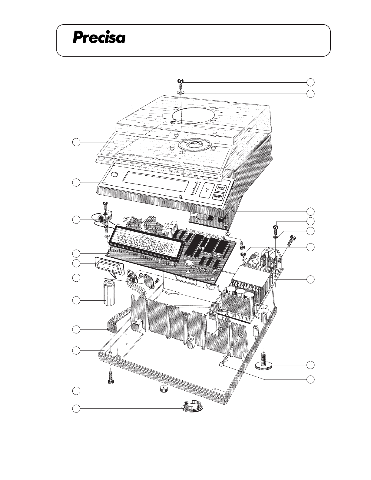
PAG OERLIKON AG
BALANCE (without weighing cell)
WAAGE (ohne Wägezelle)
15
14
9
13
12
11
10
8
7
6
5
4
3
2
1
B 02.01
17
16
18
19
20
SERIES-300 S
Page 97
PAG OERLIKON AG
BALANCE (without weighing cell)
WAAGE (ohne Wägezelle)
B 02.02
Key No. Part No. Description Bezeichnung
1 280-4003 Dust cover Staubschutz
2 300-8029 Housing's top Gehäuse-OT kpl.
3 PN 3329-014 Measure resistor Messwiderstand
4 300-7218-010 Main board Hauptprint kpl.
300-7235-010 Main board Hauptprint kpl.
5 350-7042 Cable RS 232 Kabel RS 232
6 280-4000 Cover Abdeckung
7 280-7023 Levelling unit Libelle
8 300-7001 Cable MF-Box Kabel kpl. MF-Box
9 300-7215-010 Power supply board Netzteilprint
10 300-9019 Housing's bottom Gehäuse-UT kpl.
11 280-4010 Foot Fussauflage
12 240-4042 Cover Deckel
13 280-4015 Levelling screw Stellfuss
14 PN 1100-117 Screw M4x8 ZS-Schraube M4x8
15 PN 1500-033 Washer M4 U-Scheibe M4
16 PN 1100-171 Screw M4x10 ZL-Schraube M4x10
17 PN 1500-056 Lock washer M4 Fächerscheibe M4
18 PN 1100-169 Screw M4x6 ZL-Schraube M4x6
19 PN 1100-023 Screw M3x6 ZK-Schraube M3x6
20 300-7219-010 Analogue board Analogprint
Group A1
SERIES-300 S
Page 98
PAG OERLIKON AG
BALANCE (without weighing cell)
WAAGE (ohne Wägezelle)
B 02.03
Group A2
Key No. Part No. Description Bezeichnung
1 280-4003 Dust cover Staubschutz
2 300-8029 Housing's top Gehäuse-OT kpl.
3 PN 3329-017 Measure resistor Messwiderstand
4 300-7218-010 Main board Hauptprint kpl.
300-7235-010 Main board Hauptprint kpl.
5 350-7042 Cable RS 232 Kabel RS 232
6 280-4000 Cover Abdeckung
7 280-7023 Levelling unit Libelle
8 300-7001 Cable MF-Box Kabel kpl. MF-Box
9 300-7215-010 Power supply board Netzteilprint
10 300-9019 Housing's bottom Gehäuse-UT kpl.
11 280-4010 Foot Fussauflage
12 240-4042 Cover Deckel
13 280-4015 Levelling screw Stellfuss
14 PN 1100-170 Screw M4x8 ZL-Schraube M4x8
15 PN 1500-033 Washer M4 U-Scheibe M4
16 PN 1100-171 Screw M4x10 ZL-Schraube M4x10
17 PN 1500-056 Lock washer M4 Fächerscheibe M4
18 PN 1100-169 Screw M4x6 ZL-Schraube M4x6
19 PN 1100-023 Screw M3x6 ZK-Schraube M3x6
20 300-7219-010 Analogue board Analogprint
SERIES-300 S
Page 99
PAG OERLIKON AG
BALANCE (without weighing cell)
WAAGE (ohne Wägezelle)
B 02.04
Key No. Part No. Description Bezeichnung
1 280-4003 Dust cover Staubschutz
2 300-8029 Housing's top Gehäuse-OT kpl.
3 PN 3329-012 Measure resistor Messwiderstand
4 300-7218-010 Main board Hauptprint kpl.
300-7235-010 Main board Hauprprint kpl.
5 350-7042 Cable RS 232 Kabel RS 232
6 280-4000 Cover Abdeckung
7 280-7023 Levelling unit Libelle
8 300-7001 Cable MF-Box Kabel kpl. MF-Box
9 300-7215-010 Power supply board Netzteilprint
10 300-9019 Housing's bottom Gehäuse-UT kpl.
11 280-4010 Foot Fussauflage
12 240-4042 Cover Deckel
13 280-4015 Levelling screw Stellfuss
14 PN 1100-170 Screw M4x8 ZL-Schraube M4x8
15 PN 1500-033 Washer M4 U-Scheibe M4
16 PN 1100-171 Screw M4x10 ZL-Schraube M4x10
17 PN 1500-056 Lock washer M4 Fächerscheibe M4
18 PN 1100-169 Screw M4x6 ZL-Schraube M4x6
19 PN 1100-023 Screw M3x6 ZK-Schraube M3x6
20 300-7219-010 Analogue board Analogprint
Group C1 / C2 / M1
SERIES-300 S
Page 100
PAG OERLIKON AG
BALANCE (without weighing cell)
WAAGE (ohne Wägezelle)
B 02.05
Group C3 / D1
Key No. Part No. Description Bezeichnung
1 280-4003 Dust cover Staubschutz
2 300-8029 Housing's top Gehäuse-OT kpl.
3 PN 3329-016 Measure resistor Messwiderstand
4 300-7218-010 Main board Hauptprint kpl.
300-7235-010 Main board Hauptprint kpl.
5 350-7042 Cable RS 232 Kabel RS 232
6 280-4000 Cover Abdeckung
7 280-7023 Levelling unit Libelle
8 300-7001 Cable MF-Box Kabel kpl. MF-Box
9 300-7215-010 Power supply board Netzteilprint
10 300-9019 Housing's bottom Gehäuse-UT kpl.
11 280-4010 Foot Fussauflage
12 240-4042 Cover Deckel
13 280-4015 Levelling screw Stellfuss
14 PN 1100-170 Screw M4x8 ZL-Schraube M4x8
15 PN 1500-033 Washer M4 U-Scheibe M4
16 PN 1100-171 Screw M4x10 ZL-Schraube M4x10
17 PN 1500-056 Lock washer M4 Fächerscheibe M4
18 PN 1100-169 Screw M4x6 ZL-Scraube M4x6
19 PN 1100-023 Screw M3x6 ZK-Schraube M3x6
20 300-7219-010 Analogue board Analogprint
SERIES-300 S
 Loading...