

Page 1

iPocket232
User Guide
Software Release: 4.03.00
Document No.: 23-CML000293
Revision Date: 08 Sept 06
Document Revision: 1.3
www.precidia.com
Page 2

Precidia Technologies Inc.
150 Katimavik Road, Suite 1000
Kanata, Ontario
Canada K2L 2N2
Tel: (613) 592-7557
Fax: (613) 482-5770
Web Site: http://www.precidia.com/
E-mail: [email protected]
Both the menu and features in this release may have changed from the previous
release. Please contact [email protected] if you wish to upgrade your software,
obtain a User Guide for an earlier software version, or if you have questions or
comments about using the product or document. For general inquiries, please contact
[email protected].
Disclaimer and Confidentiality Notice
The content of this document is furnished for informational use only, is subject to change without
notice, and should not be construed as a commitment by Precidia Technologies Inc. (Precidia). Precidia
assumes no responsibility or liability for any errors or inaccuracies that may appear in this document.
This document and the information disclosed herein is the confidential property of Precidia. Neither this
document nor the information contained herein shall be used, reproduced or disclosed to others without
Precidia’s written authorization.
Copyright © 2006, Precidia Technologies Inc. All rights reserved.
Published in Canada.
All trademarks and trade names are the properties of their respective owners.
Page 3

iPocket232 User Guide Table of Contents
Contents
1 Before You Start................................................................................ 1
1.1 Preview ................................................................................................. 1
1.2 Functionality and Features ....................................................................... 2
How It Works........................................................................................... 2
Features ................................................................................................. 2
1.3 iPocket232 Layout .................................................................................. 3
Front Panel ............................................................................................. 3
Hardware Interfaces .................................................................................. 4
1.4 Hardware Requirements .......................................................................... 5
Equipment Included................................................................................... 5
Additional Equipment Needed for Installation ................................................... 5
Reconfiguration ........................................................................................ 6
1.5 Software Requirements ........................................................................... 6
1.6 Configuration Requirements ..................................................................... 6
Ethernet Settings...................................................................................... 6
Serial Port Settings ................................................................................... 6
2 Setting up the iPocket232 ................................................................. 9
2.1 Connecting the Hardware......................................................................... 9
After Configuration.................................................................................... 9
2.2 Mounting the iPocket232 ........................................................................10
2.3 Setting Up the Terminal..........................................................................11
2.4 Understanding the Configuration Screen ...................................................12
2.5 Timeout During Configuration..................................................................13
2.6 Resetting to Factory (Default) Configuration ..............................................14
3 Configuring the Ethernet Settings ................................................... 15
3.1 IP Address ............................................................................................16
3.2 Subnet Mask (Static — No DHCP) ............................................................17
3.3 Gateway (Static — No DHCP) ..................................................................17
3.4 Additional Gateway ................................................................................18
Network Address .....................................................................................18
Network Mask .........................................................................................18
Gateway................................................................................................19
4 Configuring the Serial Port Settings ................................................ 21
4.1 Protocol................................................................................................22
4.2 Port Setting ..........................................................................................25
4.3 Connection Control ................................................................................27
4.4 Terminal Type (Telnet Protocol Only)........................................................29
4.5 Local Port .............................................................................................29
4.6 Remote IP ............................................................................................30
4.7 Remote Port..........................................................................................30
4.8 Fallback IP............................................................................................30
4.9 Fallback Port .........................................................................................31
4.10 Terminators (Terminated Protocol Only) ...................................................32
4.11 Packet Prefix (Transparent Protocol Only) .................................................34
23-CML000293 Precidia Technologies Inc. i
Page 4

Table of Contents iPocket232 User Guide
4.12 Maximum Inter-Character Delay.............................................................. 34
4.13 Preferred Packet Size............................................................................. 35
4.14 Initial String (Transparent Protocol Only).................................................. 35
5 Configuring the Security Settings .................................................... 37
5.1 Console Password ................................................................................. 38
Setting the Console Password ..................................................................... 38
Viewing the Console Password .................................................................... 38
Clearing the Console Password.................................................................... 38
5.2 Remote Password.................................................................................. 39
Setting the Remote Password ..................................................................... 39
Viewing the Remote Password .................................................................... 39
Clearing the Remote Password .................................................................... 39
5.3 Web Server .......................................................................................... 40
5.4 Access Userid ....................................................................................... 41
5.5 Access Password ................................................................................... 41
Setting the Access Password ...................................................................... 41
Viewing the Access Password...................................................................... 41
Clearing the Access Password ..................................................................... 42
5.6 SNMP Server ........................................................................................ 42
5.7 SNMP Settings ...................................................................................... 42
5.8 IPsec Tunnels #1 and #2 ....................................................................... 43
Protocol ................................................................................................ 44
Secure Address....................................................................................... 45
SPI ...................................................................................................... 46
Network Address ..................................................................................... 46
Network Mask ........................................................................................ 46
Network Gateway .................................................................................... 46
Encode/Authenticate Keys ......................................................................... 47
6 System Settings .............................................................................. 49
6.1 Unit ID Value........................................................................................ 49
6.2 Web Page Download .............................................................................. 50
6.3 Firmware Download............................................................................... 50
6.4 Display System Status ........................................................................... 51
6.5 Dump System Log................................................................................. 51
6.6 Delete System Log ................................................................................ 52
6.7 Perform Self Test .................................................................................. 52
6.8 Reset Unit ............................................................................................ 53
6.9 Simple Network Time Protocol................................................................. 53
SNTP Settings ........................................................................................ 54
More Information .................................................................................... 55
ii Precidia Technologies Inc. 23-CML000293
Page 5

iPocket232 User Guide Table of Contents
7 Accessing System Information ........................................................ 57
7.1 System Status.......................................................................................57
Accessing the System Status Page ...............................................................57
Understanding the System Status Page .........................................................58
7.2 System Log ..........................................................................................60
Accessing the System Log ..........................................................................60
Understanding the System Log ....................................................................61
7.3 Static Web Page ....................................................................................65
Creating Static Web Pages .........................................................................65
Accessing the Static Web Page ....................................................................65
Appendix A: Glossary of Terms and Acronyms................................... A-1
Appendix B: Troubleshooting and Support......................................... B-1
Appendix C: Specifications and Warranty .......................................... C-1
Appendix D: Connecting with Telnet .................................................. D-1
Appendix E: Pinouts and Power Supply ............................................. E-1
Appendix F: MCC ............................................................................... F-1
Appendix G: Regulatory
Compliance G-1
23-CML000293 Precidia Technologies Inc. iii
Page 6

Table of Contents iPocket232 User Guide
iv Precidia Technologies Inc. 23-CML000293
Page 7

1 Before You Start
1.1 Preview
Each section in this Guide is a step in the process of installing and configuring your
iPocket232:
1 Before You Start
Familiarize yourself with the features and installation requirements of the unit.
2 Setting up the iPocket232
Set up the hardware and configure the unit via terminal software.
3 Configuring the Ethernet Settings
Input the IP address, subnet mask, and gateway address for the unit.
4 Configuring the Serial Port Settings
Configure the protocol, speed, connection control, and port information.
5 Configuring the Security Settings
Configure the remote, console, and Web passwords, SNMP, and IPSec.
6 System Settings
If necessary, have your network administrator configure the advanced settings,
including downloads and system logging options.
7 Accessing System Information
Find out how to access the system information locally or remotely.
Appendices at the back of this guide also provide valuable reference information:
A Glossary of Terms and Acronyms
B Troubleshooting and Support
C Specifications and Warranty
D Connecting with Telnet
E Pinouts and Power Supply
F Modem Connection Control
23-CML000293 Precidia Technologies Inc. 1
Page 8
1 Before You Start iPocket232 User Guide
1.2 Functionality and Features
How It Works
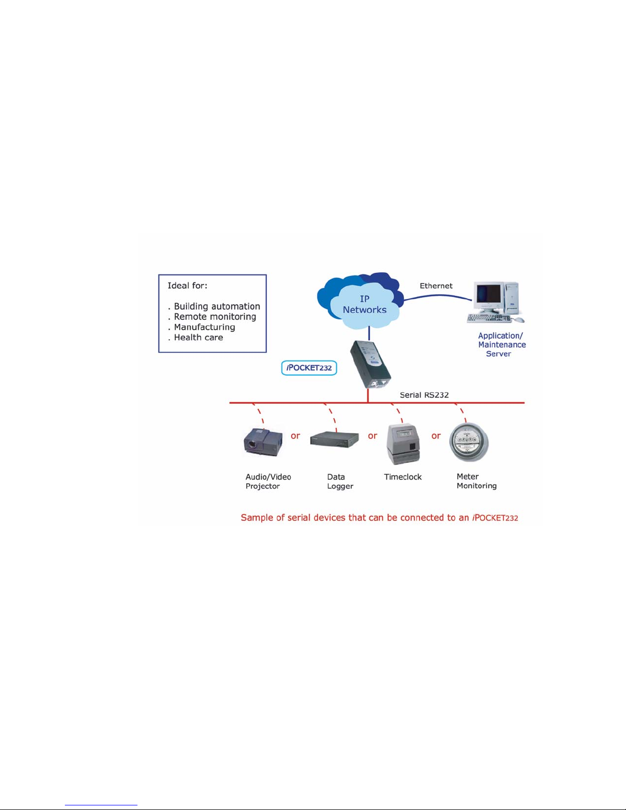
Precidia products connect serial devices and IP networks. A device sends information
to the unit through the serial port. This information is processed according to the
protocol set in the Serial Port Settings, then transferred to the Ethernet side of the unit.
The unit then converts the information to IP compatible format and sends it out the
Ethernet port to the remote server, according to the parameters set in the Ethernet
Settings. The process is reversed when information is received from the remote server.
The figure below illustrates an example configuration of the iPocket232 in a network.
Features
The iPocket232 has many useful features, allowing you to:
• Replace an existing modem with the iPocket232 without making any other
changes to the network
• Configure settings locally via the COM port, or remotely using telnet
• Display static Web pages using a built-in Web page server
• Display dynamic System Status and System Log pages through the built-in Web
server or the Configuration screen
• Manage information with SNMPv2c (Simple Network Management Protocol)
2 Precidia Technologies Inc. 23-CML000293
iPocket232 — Network Configuration
Page 9
iPocket232 User Guide 1 Before You Start
• Tap remotely into the datastream to monitor data and assist in debugging
• Provide security through passwords and IPsec
• Use a primary and a backup server (automatic switchover on failure)
• Capture statistics and log system information internally
• Perform firmware upgrades using TFTP (Trivial File Transfer Protocol) or via the
local COM port
• Control and refine connection settings with:
- Automatic connection in tcp(tunnel) and tcp-client modes, to establish a
connection to the server as soon as the first data byte is received on the serial
port
- Connection recovery, to ensure the session remains active
- Modem Connection Control that allows the iPocket232 to act as a Hayescompatible modem to your serial device
• Support the following network protocols:
ARP DHCP Ethernet, IEEE 802.3
FTP HTTP ICMP
IP IPsec (manually keyed) SNMPv2c
TCP telnet TFTP (download only)
UDP
1.3 iPocket232 Layout
Front Panel
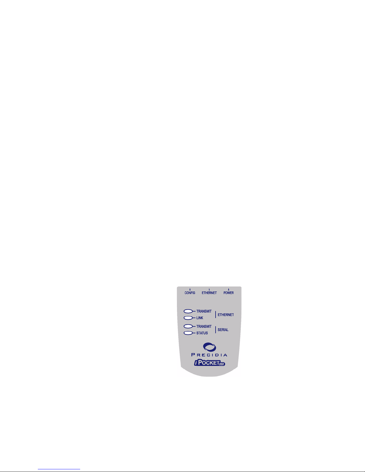
Table 1.1 describes the function of each indicator lamp.
23-CML000293 Precidia Technologies Inc. 3
iPocket232 Front Panel
Page 10
1 Before You Start iPocket232 User Guide
Table 1.1: Front Panel Indicator Lamps
Indicator Lamp Description
LINK
On (solid): when the Ethernet port has a valid
connection to a 10BaseT Ethernet network.
ETHERNET
TRANSMIT
Flashes: when the unit has control of the line and
is sending data on the network.
Off: when receiving data.
TRANSMIT
Flashes: when the unit is sending or receiving
data through the serial port.
On (solid): while in configuration mode.
STATUS
SERIAL
Off: Unit incorrectly configured, or the serial
port is disabled.
Slow flash: Correctly configured, in idle mode.
Fast flash: Correctly configured, terminal has
communicated.
On (solid): Correctly configured, connected.
NOTE: See Appendix B, Troubleshooting and Support, for descriptions of how indica-
tor lamps can be used for troubleshooting.
Hardware Interfaces
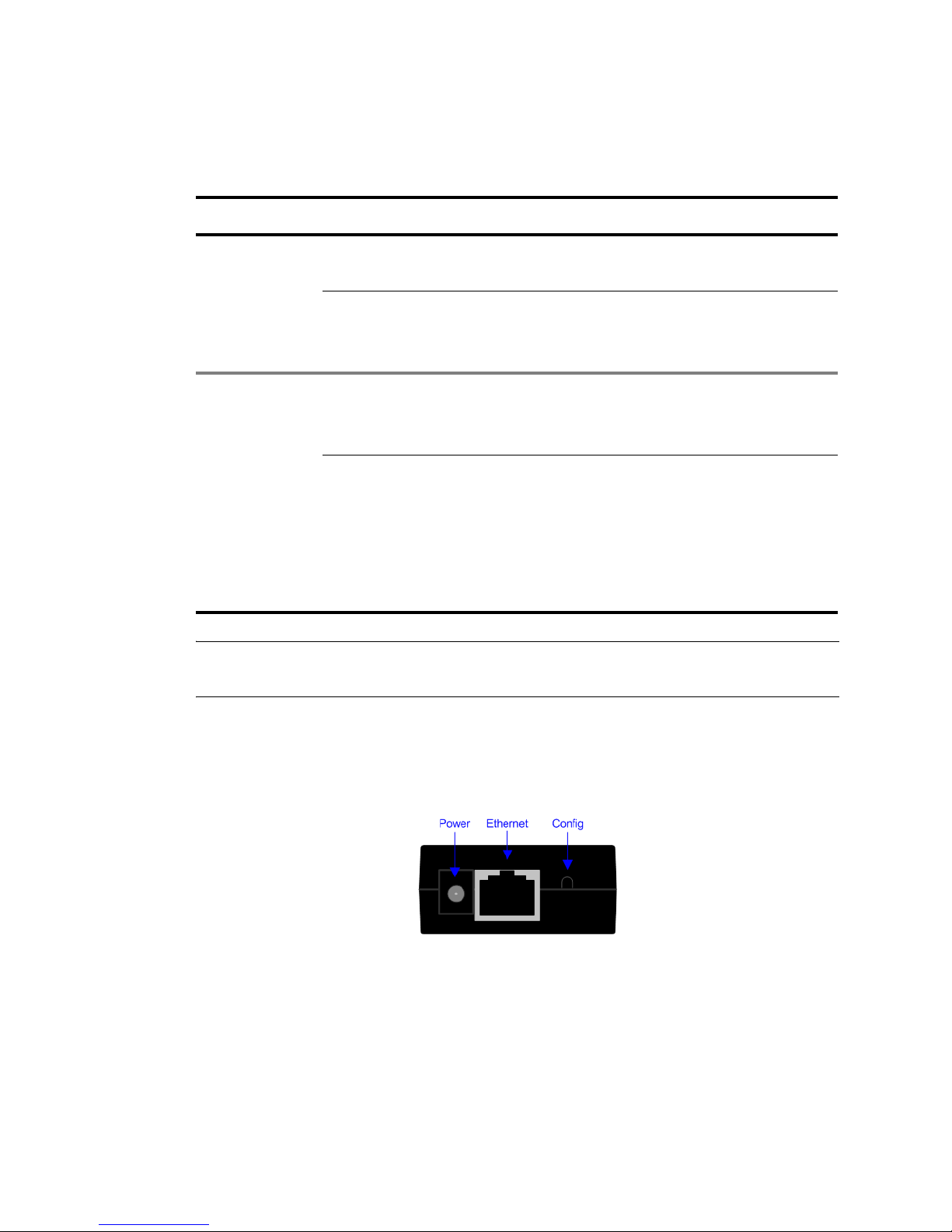
The iPocket232 has 4 interfaces, each described in Table 1.2. The figure below shows
the top view of the iPocket.
Top View of iPocket232
4 Precidia Technologies Inc. 23-CML000293
Page 11

iPocket232 User Guide 1 Before You Start
.
Table 1.2: Connectors
Port Location Description
CONFIG Top of unit
ETHERNET Top of unit
POWER Top of unit
SERIAL Bottom of
unit
1.4 Hardware Requirements
Activates local configuration through the serial
port. (To activate, press and hold the recessed
CONFIG button for several seconds using a ball
point pen or similar object.)
Accepts RJ-45 connector for direct connection
to 10BaseT Ethernet network.
NOTE: If connecting directly to another Ether-
net device, use a cross-over cable. If connecting
to a 100BaseT network, your hub must support
automatic switching to 10BaseT.
Accepts the Precidia-supplied 9V power adapter.
Accepts DB-9 serial cable for operation and configuration.
Equipment Included
The following items are included with your iPocket232 device:
• one (1) iPocket232 device
• one (1) power adapter
• one (1) mounting bracket
Additional Equipment Needed for Installation
To complete the hardware installation, you will need the iPocket232 package, along
with the following equipment:
• one (1) PC with terminal software, or a dumb terminal for configuration
• one (1) Ethernet cable for your network connection.
• If you are connecting the iPocket232 to a DTE (Data Terminal Equipment) device,
or as a modem replacement:
- one (1) RS-232 serial cable for configuration and operation
23-CML000293 Precidia Technologies Inc. 5
Page 12

1 Before You Start iPocket232 User Guide
• If you are connecting the iPocket232 to a DCE (Data Communication Equipment)
device:
- one (1) RS-232 serial cable for configuration
- one (1) straight through modem serial cable (DB-9 male to DB-9 female) for
connecting your DCE serial device after configuration
TIP: How do you know if your serial device is DCE or DTE?
• DCE devices generally have a female (receptacle) DB-9 connector. Examples of
DCE devices include the iPocket232, modems, Digital Service Units (DSU),
Channel Service Units (CSU), and most communications equipment.
• DTE devices generally have a male (pin) DB-9 connector. Examples of DTE
devices include communications servers, terminals, serial printers, and PCs with
native RS-232-E serial ports.
Reconfiguration
After your iPocket232 is operational, you will require a standard RS-232 serial cable
and a PC or dumb terminal to locally reconfigure the unit.
NOTE: You can also reconfigure the iPocket232 remotely using telnet, if you have set
the Remote Password. See Appendix D: Connecting with Telnet.
1.5 Software Requirements
You will need terminal software (or a dumb terminal) to locally configure the unit.
Please see: Section 2.3, Setting Up the Terminal‚ on page 11, for further details.
1.6 Configuration Requirements
The following settings are the basic requirements for configuring the unit. You may
need to configure other settings depending on your set-up, and the Protocol you are
using.
Ethernet Settings
• IP Address, Subnet Mask, Gateway: the addressing information for the unit and
the network. Leave at zero (000.000.000.000) if using DHCP (Dynamic Host
Configuration Protocol) server
Serial Port Settings
• Protocol: the protocol used by the connected device
• Port Setting: port settings of the connected device
• Local Port: port number on the unit (as required)
6 Precidia Technologies Inc. 23-CML000293
Page 13

iPocket232 User Guide 1 Before You Start
• Remote Port and Remote IP: port number and IP address of remote host (as
required)
• Fallback Port and Fallback IP: backup remote host address (optional)
Security Settings
• Remote Password: must be configured to enable remote access and configuration
• Console Password (optional)
• Web server access user ID and password (optional)
23-CML000293 Precidia Technologies Inc. 7
Page 14

1 Before You Start iPocket232 User Guide
8 Precidia Technologies Inc. 23-CML000293
Page 15
2 Setting up the iPocket232
2.1 Connecting the Hardware
CAUTION: Use the 9V power adapter supplied by Precidia, or an
!
1 Connect the power adapter to the POWER port of the unit.
2 Connect the Ethernet cable to the ETHERNET port of the unit.
3 Connect the serial cable to the serial port of the unit.
adapter conforming exactly to the specifications in Appendix E: Pinouts
and Power Supply. Use of alternate power adapters can result in hardware damage and will render the warranty null and void!
4 Plug the power adapter into a power outlet.
5 Connect the serial cable to one of the COM ports on your PC.
6 Follow Section 2.2 to set up your terminal software and access the Configuration
screen.
7 Configure the unit (Sections 3 through 6).
NOTE: You must set the Remote Password locally before you can configure the
iPocket232 remotely.
After Configuration
1 Disconnect the serial cable from the COM port of your PC.
2 Connect your serial device to the serial port of the iPocket232 using the appropriate
cable. (See Section 1.4, Hardware Requirements‚ on page 5.)
23-CML000293 Precidia Technologies Inc. 9
Page 16

2 Setting up the iPocket232 iPocket232 User Guide
3 Connect the Ethernet cable to a hub or router if you have not already done so.
4 Ensure the LINK lamp is lit to indicate a valid Ethernet connection, and the
STATUS lamp is flashing to indicate the unit is ready to transmit/receive data.
5 If you know the IP address of the iPocket232, ping the unit to ensure you have a
valid network connection. (See Check IP Address (Ping) on page B-3.)
2.2 Mounting the iPocket232
The iPocket232 comes with a mounting bracket that you can use to conveniently
mount the unit. Once the mounting bracket is in place, the iPocket232 can be easily
clipped on or removed as needed.
To mount the iPocket232 to a wall or other surface:
1 Affix the mounting bracket to the wall using two #6 pan head screws.
2 Clip the iPocket232 to the mounting bracket.
You can also attach a rail adapter (http://www.phoenixcontact.com/, part # USA 10) to
the mounting bracket to secure the iPocket232 to a DIN rail.
To mount the iPocket to a DIN rail:
1 Affix the recommended DIN adapter to the mounting bracket using two #6 or M3
thread forming screws, 3/8” (10 mm) long.
2 Clip the mounting bracket onto the DIN rail.
3 Clip the iPocket232 to the mounting bracket.
10 Precidia Technologies Inc. 23-CML000293
Mounting the iPocket to a DIN Rail
Page 17

iPocket232 User Guide 2 Setting up the iPocket232
2.3 Setting Up the Terminal
Once the iPocket232 is connected to your PC, you can access the Configuration screen
using terminal software.
You may use any terminal emulation software as HyperTerminal, which comes standard with Windows operating systems, or Procomm Plus (Symantec). For further help
on using Hyper Terminal, please refer to the Using HyperTerminal Help Guide at:
http://www.precidia.com/products/documentation.html.
IMPORTANT! WINDOWS NT/2000/XP USERS:
If using HyperTerminal to perform firmware upgrades, or to download static Web
pages to the Precidia unit, you need to use the latest version of HyperTerminal.
To obtain your free HyperTerminal upgrade, visit http://www.hilgraeve.com.
1 Start your terminal program.
2 Select the correct COM port in your terminal program (usually Com1 or Com2).
3 Configure the terminal with the following settings:
• Bits per second: 9600 (required)
• Data bits: 8
• Parity: None
• Stop bits: 1
• Flow control: Hardware
NOTE: The Data Bits, Parity, Stop Bits, and Flow control settings listed above are
recommended settings. Configuration can be accessed using any settings at 9600 bps.
23-CML000293 Precidia Technologies Inc. 11
Page 18

2 Setting up the iPocket232 iPocket232 User Guide
4 Using a ballpoint pen or similar item, press and hold the recessed CONFIGURE
button at the rear of the unit for several seconds, until the initial Configuration
screen appears (as shown below).
If the screen does not appear, refer to Appendix B:, Troubleshooting and Support.
,-----------------------------------------------------------------------------.
| Precidia iPocket232 Configuration v4.03.00 |
|-----------------------------------------------------------------------------|
| Device Settings: | |
| | |
| 1) Ethernet: 0.0.0.0 | |
| | |
| 2) Serial Port: disabled | |
| | |
| *) Save Current Configuration | |
| -) Exit Configuration (no save) | |
| $) Security Settings | |
| #) System Settings | |
| ?) Refresh this Screen | |
`-----------------------------------------------------------------------------'
Change which option?
Initial Configuration Screen
NOTE: The SERIAL TRANSMIT lamp stays illuminated throughout the configuration
process.
2.4 Understanding the Configuration Screen
The left half of the Configuration screen displays the Device Settings menu and the
right half of the screen displays the sub-menu of the option you select.
Table 2.1 provides a description of the menu items. Type the number or character
bracketed at the start of the line to chose a menu item.
NOTE: Pressing ESC cancels the current action and returns you to the previous
prompt.
12 Precidia Technologies Inc. 23-CML000293
Page 19
iPocket232 User Guide 2 Setting up the iPocket232
.
Table 2.1: Device Settings Menu Options
Menu
No.
1) Ethernet
2) Serial Port
*) Save Current
-) Exit Configura-
$) Security Settings
#) System Settings
?) Refresh this
Menu Item Description
Configuration
tion (no save)
Screen
Configure the local network information before the
device is placed on a network so it does not cause a
problem with the existing LAN, or configure automatically with a DHCP server.
Configure host addresses and the protocols being
used by the serial device.
Save changes and exit from configuration mode.
Resets the unit.
Exit from the configuration mode without saving
any changes. Resets the unit if configuring locally.
Configure all passwords, IPsec, and SNMP.
For administrator only. Perform Web page and
firmware downloads, and view system information.
Refresh the current Configuration screen.
2.5 Timeout During Configuration
After 4 minutes of inactivity the timeout notification appears under the prompt, as
shown below. Any unsaved changes will be lost.
Change which option?
!timeout! (changes not saved)
Timeout Notification
You must then press and hold the recessed CONFIGURE button for several seconds, or
re-establish your remote telnet connection, to access configuration again and re-enter
your changes.
NOTE: Typing any character, or typing “?” to refresh the screen, will restart the
4-minute timer.
23-CML000293 Precidia Technologies Inc. 13
Page 20

2 Setting up the iPocket232 iPocket232 User Guide
2.6 Resetting to Factory (Default) Configuration
You may need to reset to “factory” settings if you have configured and subsequently
lost a Console Password, or if you wish to completely reconfigure the unit. The procedure below will delete your previous configuration and revert all settings to factory
default.
1 Unplug the power cord from the back of the unit.
2 Press and hold the recessed CONFIGURE button and plug the power cord back in to
the POWER port.
3 Continue to press and hold the recessed CONFIGURE button for 15 seconds.
The Configuration screen appears, reset to the factory settings.
4 Reconfigure the unit.
5 Type “*” to save the new configuration.
NOTE: If you do not save the new settings, the unit will restart with the previously
saved settings.
14 Precidia Technologies Inc. 23-CML000293
Page 21

3 Configuring the Ethernet
Settings
The Ethernet Settings sub-menu allows you to specify a unique IP address for your
iPocket232 to enable communication over an IP network and with the remote host(s).
If you are using a DHCP server, leave all Ethernet Settings at zero (0.0.0.0). The
settings will always appear as zeros in the menu regardless of the values assigned by
the DHCP server.
To configure or change the Ethernet Settings, choose Ethernet from the Device
Settings
The Ethernet Settings sub-menu appears on the right side of the Configuration screen,
as shown below.
menu.
,-----------------------------------------------------------------------------.
| Precidia iPocket232 Configuration v4.03.00 |
|-----------------------------------------------------------------------------|
| Device Settings: | |
| | |
| 1) Ethernet: 0.0.0.0 | |
| | |
| 2) Serial Port: disabled | |
| | |
| *) Save Current Configuration | |
| -) Exit Configuration (no save) | |
| $) Security Settings | |
| #) System Settings | |
| ?) Refresh this Screen | |
`-----------------------------------------------------------------------------'
Change which option?
NOTE: Remember to save your changes by typing "*" to exit configuration!
23-CML000293 Precidia Technologies Inc. 15
Ethernet Settings Sub-menu
Page 22

3 Configuring the Ethernet Settings iPocket232 User Guide
3.1 IP Address
An IP address is an identifier for computers or devices on a TCP/IP network. Make
sure that the IP address you assign is not in use by any other device on your network.
IP addresses are made up of four numbers from 0 to 255, separated by periods.
NOTE: You can determine the IP address of your unit through the System Settings
menu, if it is a dynamically allocated (DHCP) IP Address, or a Static IP Address.
Please refer to 6.4: Display System Status for further information.
3.1.1 DHCP - Dynamic IP Address
DHCP (Dynamic Host Configuration Protocol) allows you to dynamically allocate IP
addresses to devices on a TCP/IP network.
NOTE: For further help on DHCP Administration, please refer to our DHCP Admin-
istrator Help Guide at http://www.precidia.com/products/documentation.html.
iPocket232s come configured with the IP address and subnet mask set at 0.0.0.0,
which automatically enables DHCP.
NOTE: The DHCP server must be on the same physical subnet as the iPocket232.
To enable DHCP configuration:
1 Choose Ethernet Settings from the Device Settings menu. (If the IP Address and
Subnet Mask are both 0.0.0.0, then DHCP is already enabled.)
2 Choose
3 Type
4 Choose
IP Address from the Ethernet Settings sub-menu.
0.0.0.0 at the prompt and press Enter.
Subnet Mask from the Ethernet Settings sub-menu.
5 Type 0.0.0.0 at the prompt and press Enter.
The unit should automatically obtain the Ethernet Settings from the DHCP server.
NOTE: The settings obtained from the DHCP server may change if the unit is reset,
since they will be lost and re-negotiated.
16 Precidia Technologies Inc. 23-CML000293
Page 23

iPocket232 User Guide 3 Configuring the Ethernet Settings
3.1.2 Static - (No DHCP) IP Address Settings
If you decide not to allow DHCP to automatically detect and assign your iPocket232’s
IP Address, you may enter the IP Address manually.
To enter or change the IP address:
1 Choose Ethernet from the Device Settings menu.
2 Choose IP Address from the Ethernet Settings sub-menu.
You are prompted to enter the IP address of the device.
3 Type the unique IP address at the prompt (in the format xxx.xxx.xxx.xxx) and press
Enter.
3.2 Subnet Mask (Static — No DHCP)
The subnet mask is used to determine what subnet an IP address belongs to. The mask
allows a router to determine the network and host addresses, and forward data packets
correctly.
To enter or change the Subnet Mask:
1 Choose Ethernet from the Device Settings menu.
2 Choose Subnet Mask from the Ethernet Settings sub-menu.
You are prompted to enter the subnet mask of the device.
3 Type the subnet mask at the prompt (in the format xxx.xxx.xxx.xxx) and press
Enter.
3.3 Gateway (Static — No DHCP)
If the device will be communicating with a host that is not on the local subnet, you
must specify the router address (gateway) that will forward data to the destination. If
the destination is within the LAN and can be accessed without passing through a
router, you can leave this field blank (0.0.0.0). This setting is the default gateway.
To enter or change the
1 Choose Ethernet from the Device Settings menu.
Gateway:
2 Choose
Gateway from the Ethernet Settings sub-menu.
You are prompted to enter the IP address of the gateway.
23-CML000293 Precidia Technologies Inc. 17
Page 24

3 Configuring the Ethernet Settings iPocket232 User Guide
3 Type the gateway address at the prompt (in the format xxx.xxx.xxx.xxx) and press
Enter.
3.4 Additional Gateway
The Additional Gateway option allows you to specify a second gateway (router) for a
specific network address.
You can use the Additional Gateway to run the SNMP (Simple Network Management
Protocol) manager on a computer on another network. You can also telnet to the
iPocket232, or ping to check its status, from a computer on another network. In this
way, if your primary network goes down, you can still access the iPocket232 and
remotely reconfigure it to another network.
NOTE: The Additional Gateway must be on the same subnet as the device.
Network Address
If the destination IP address of a packet matches this Network Address and the
Network Mask, it is forwarded to the second gateway address defined below.
To enter or change the Network Address:
1 Choose Ethernet from the Device Settings menu.
2 Choose Network Address from the Ethernet Settings sub-menu.
You are prompted to enter the IP address of this network.
3 Type the address at the prompt (in the format xxx.xxx.xxx.xxx) and press Enter.
Network Mask
To enter or change the Network Mask:
1 Choose
2 Choose
Ethernet from the Device Settings menu.
Network Mask from the Ethernet Settings sub-menu.
You are prompted to enter the subnet mask of the device.
3 Type the network mask at the prompt (in the format xxx.xxx.xxx.xxx) and press
Enter.
18 Precidia Technologies Inc. 23-CML000293
Page 25

iPocket232 User Guide 3 Configuring the Ethernet Settings
Gateway
The Gateway specified under Additional Gateway defines the address of the second
router (gateway). Packets with destination addresses matching the Network Address
and Subnet Mask configured above are sent to the additional gateway.
NOTE: The Additional Gateway must be on the same subnet as the device.
To enter or change the Gateway:
1 Choose Ethernet from the Device Settings menu.
2 Choose Gateway under Additional Gateway from the Ethernet Settings sub-menu.
You are prompted to enter the IP address of the gateway.
3 Type the gateway address at the prompt (in the format xxx.xxx.xxx.xxx) and press
Enter.
23-CML000293 Precidia Technologies Inc. 19
Page 26

3 Configuring the Ethernet Settings iPocket232 User Guide
20 Precidia Technologies Inc. 23-CML000293
Page 27

4 Configuring the Serial Port
Settings
The Serial Port Settings sub-menu allows you to choose the protocol for communicating with the remote server.
To configure or change the Serial Port Settings choose Serial Port from the Device
Settings
The
screen, an example of which is shown below.
NOTE: Once you choose a protocol, different options appear in the sub-menu. Set the
Protocol option first.
menu.
Serial Port Settings sub-menu appears on the right side of the Configuration
,-----------------------------------------------------------------------------.
| Precidia iPocket232 Configuration v4.03.00 |
|-----------------------------------------------------------------------------|
| Device Settings: | Serial Port Settings: |
| | |
| 1) Ethernet: 0.0.0.0 | A) Protocol: Transparent (tcp) |
| | B) Port Setting: 300 bps 8N1 [no] |
| 2) Serial Port: Transparent | C) Connection Control: Automatic |
| | |
| | D) Local Port: 0 |
| | E) Remote IP: 0.0.0.0 |
| | F) Remote Port: 0 |
| | G) Fallback IP: 0.0.0.0 |
| | H) Fallback Port: 0 |
| | |
| *) Save Current Configuration | I) Packet Prefix: none |
| -) Exit Configuration (no save) | J) Max Inter-Char Delay: 0 |
| $) Security Settings | K) Preferred Packet Size: 0 |
| #) System Settings | |
| ?) Refresh this Screen | L) Initial String: (not set) |
`-----------------------------------------------------------------------------'
Change which option?
NOTE: Remember to save your changes by typing "*" to exit configuration!
23-CML000293 Precidia Technologies Inc. 21
Example of the Serial Port Settings Sub-menu
Page 28

4 Configuring the Serial Port Settings iPocket232 User Guide
4.1 Protocol
The Protocol setting defines how the iPocket232 communicates with the remote
server. The Protocol setting has two parts: data formatting and session mode.
The first part of the Protocol setting, data formatting, indicates how to parse or
process the data stream to provide compatibility with the remote server. Table 4.1
describes the data formatting options.
Table 4.1: Data Formatting Options
Menu Item Description
disabled
ComPort
Control
Default setting. The unit will not accept any host initiated or local
sessions. You must choose a protocol for the unit to become active.
IMPORTANT! The iPocket232 is a DCE device and therefore
cannot remotely control the DTR and RTS signals, nor monitor the
DSR, CTS, and DCD signals in compliance with RFC2217. Port
speed, parity, data width, and handshaking all function correctly.
Extends a serial link to allow remote configuration and control of a
serial port. Upon receipt of a message containing Com Port Control
commands, the iPocket232 extracts the command information from
the message and sets the following parameters of the serial port:
baud rate, data length, parity bits, stop bits, DSR signal, and flow
control.
Once the serial port is set, the iPocket232 forwards the data to the
serial device unchanged. If any changes to the Com Port or modem
line occur, the iPocket232 will automatically send a notification
packet to the host.
Once the transaction/transmission is complete, the iPocket232 automatically resets to the Port Setting defined in the
tings
sub-menu until the next message is received.
Serial Port Set-
22 Precidia Technologies Inc. 23-CML000293
Telnet Com Port Control is defined in RFC2217.
If you are connecting only one iPocket232 to a PC and the application requires COM port connection, you can use Com Port Redirector software if your application is not affected by the limitations
noted above. You can find more information and purchase this software on the Precidia Web site at http://www.precidia.com/products/
soft_utilities.html.
Page 29

iPocket232 User Guide 4 Configuring the Serial Port Settings
Table 4.1: Data Formatting Options
Menu Item Description
Telnet
Turns the iPocket232 into either a telnet client (most common use)
or a telnet server and allows the user to telnet out of the iPocket232
to a remote server, such as a UNIX workstation.
The standard connection control options are supported. By leaving
the Connection Control parameter at Automatic (default setting), the
user can initiate the telnet session by pressing any alphanumeric key.
If the Connection Control parameter is set to DTR/DSR Control, the
iPocket232 tries to open a telnet session as soon as DSR is detected
from the terminal, but the timeout function of most hosts makes this
option somewhat unreliable.
Telnet-Client: The most common use of the telnet protocol. To create a telnet client, select tcp-client as the session mode. This configuration allows the iPocket232 to communicate with the telnet
server at the configured Remote IP address and Remote Port.
Telnet-Server: To create a telnet server, select tcp-server as the
session mode when configuring this protocol. The iPocket232 listens on port 23, and the Remote Password must be disabled so that
the standard configuration program is not listening on that port. You
can configure Telnet to listen on a port other than 23 (but above
1024 to avoid using reserved ports).
Transparent
Typical setting. No alterations are made to the data stream, nor is it
parsed in any way. Data is collected until either the preferred packet
size is reached or there is a pause between characters that exceeds
the inter-character timer. The buffer is then transmitted as a single
frame. Preferred Packet Size and Max Inter-Char Delay can be left
at the default settings (0), and the unit will automatically determine
a reasonable setting based on the current serial port speed.
Transparent protocol includes the option “Packet Prefix”, which
allows you to include a header in the packet defining it’s length. See
Section 4.11, Packet Prefix (Transparent Protocol Only)‚ on
page 34.
23-CML000293 Precidia Technologies Inc. 23
Page 30

4 Configuring the Serial Port Settings iPocket232 User Guide
Table 4.1: Data Formatting Options
Menu Item Description
Terminated
No alterations are made to the data stream, but incoming data is
checked for known "end-of-record" characters, or "terminators",
that identify the end of a block so that it can be transmitted as a
whole to the remote host. If this mode is selected, you will be
prompted to enter up to six Terminators in their ASCII decimal form
(e.g. <CR> = 13). This is ideal when the host requires pre-parsing of
the data, such as with an AS/400.
NOTE: To use zero (null) as a terminator, you must set it as Termi-
nator #1. Any zeroes after the first terminator are ignored.
The second part of the Protocol setting, session mode, determines how the data
channel between the terminal and the server is established. Communications between
the device and the host can be over TCP or UDP channels. In addition, the device can
initiate a session immediately, or wait until either the server (host) or the terminal
(client) attempts to establish a connection. Table 4.2 describes the session mode
options.
Table 4.2: Session Mode Options
Menu Item Description
tcp(tunnel)
Typical configuration for most applications.
Use tcp(tunnel) mode when the iPocket232 must be able to initiate
TCP connections and accept TCP connections from the host. In this
configuration, the iPocket232 can communicate with the TCP/IP
host as if it were virtually connected. Local Port, Remote Port, and
Remote IP must be configured. Sections 4.6 through 4.10 describe
how to configure ports and IP addresses.
tcp-client
Use tcp-client mode when all transactions must be initiated by the
terminal. This ensures that a TCP/IP host (server) can never initiate
communications with the terminal.
tcp-server
Use tcp-server mode when the TCP/IP host must never be interrupted by the terminal unless it authorizes a connection. This
ensures that data from the terminal will be discarded until the server
establishes a session. As a security feature, the host address must
match the Remote IP configured in the
necessary to match the Remote Port). Local Port and Remote Port
must be configured. Sections 4.6 through 4.10 describe how to configure ports and IP addresses.
Serial Port Settings (it is not
24 Precidia Technologies Inc. 23-CML000293
Page 31
iPocket232 User Guide 4 Configuring the Serial Port Settings
Table 4.2: Session Mode Options
Menu Item Description
udp
Similar to tcp(tunnel) mode, use UDP mode when reception
acknowledgement of the data packets is not required. UDP is a connectionless channel, therefore, it is not necessary to initiate or accept
connections. This makes for slightly faster data flow. Setting the
Remote IP address to all zeros puts UDP into "reply mode" and the
iPocket232 will send data to the last address it received data from.
For peer-to-peer communication, the host address must match the
Remote IP defined in configuration.
To set or change the Protocol:
1 Choose Serial Port from the Device Settings menu.
2 Choose Protocol from the Serial Port Settings sub-menu.
You are prompted to choose a new protocol, as shown below.
A. disabled B. ComPort Control C. Telnet D. Transparent
E. Terminated
1. tcp(tunnel) 2. tcp-client 3. tcp-server 4. udp
Choose new protocol (letter+number) or press ESC to cancel:
3 Type the letter (A to E), plus the number (1 to 4), that corresponds to your selection
and press Enter.
4.2 Port Setting
The serial port settings of the iPocket232 must match the settings of the attached serial
device to enable communication. Settings include bit rate, data width, error detect,
framing, and flow control.
NOTE: To avoid data loss, choose hardware flow control if you set the port speed to
19 200 bps or higher.
Choosing a Protocol
23-CML000293 Precidia Technologies Inc. 25
Page 32

4 Configuring the Serial Port Settings iPocket232 User Guide
The flow control options are described Table 4.3 .
Table 4.3: Flow Control Options for Port Setting Parameter
Option Description
None
h/w
(rts/cts)
s/w
(xon/xoff)
Default
No flow control enabled. Data may be lost due to overflow during
high speed communication.
Hardware handshaking uses the RTS/CTS (Request To Send/Clear
To Send) signal lines for flow control on the COM port. Hardware
handshaking works by altering voltage levels on these lines. When
the remote end is ready to receive data, it asserts the CTS signal to
tell the iPocket232 to start transferring data. If the remote end is
unable to accept the data as fast as it is received from the
iPocket232, the remote end negates CTS, and the iPocket232 suspends data transfer. When the remote end is ready for more data, it
asserts CTS again.
When the iPocket232 is ready to receive data, it asserts the RTS
signal. If the iPocket232 cannot accept data as quickly as the device
is passing data, it negates RTS. The iPocket232 asserts RTS again
when it is ready to resume receiving data. This setting can be used
for the majority of installations.
Software handshaking requires that XON/XOFF characters are
asserted and obeyed on the COM port. XON is used by either the
iPocket232 or the remote host to signal the other end to start sending data. XOFF can also be used by either the iPocket232 or the
remote host to signal the other to stop sending data.
NOTE: XON/XOFF characters included in a data transmission are
interpreted as flow control characters and will cause transmission
problems. This option is not recommended for binary data transmission.
To set or change the
Port Setting:
1 Choose Serial Port from the Device Settings menu.
26 Precidia Technologies Inc. 23-CML000293
Page 33

iPocket232 User Guide 4 Configuring the Serial Port Settings
2 Choose Port Setting from the Serial Port Settings sub-menu.
You are prompted to enter one item from each column to configure the port, as
shown below.
Port configuration is made up of the several different parameters:
Bit Rate Data Width Error Detect Framing Flow Control
~~~~~~~~~~~~~~ ~~~~~~~~~~~~~~ ~~~~~~~~~~~~~~ ~~~~~~~~~~~~~~ ~~~~~~~~~~~~~~~
A. 300 8. 8 bits N. no parity 1. 1 stop bit N. none
B. 600 7. 7 bits O. odd parity 2. 2 stop bits H. h/w (rts/cts)
C. 1200 9. 9 bits E. even parity S. s/w (xon/xoff)
D. 2400 M. mark parity
E. 4800 S. space parity
F. 9600
G. 19200
H. 38400
I. 57600
J. 115200
Enter one item from each column to configure port (eg. C-7E1-H):
Choosing the Port Configuration
3 Type the letter or number from each column corresponding to your desired settings,
and press Enter.
NOTE: Serial ports communicate using the RS-232 serial (bit-stream) protocol. Each
byte of data transferred through the serial port consists of a predetermined number of
bits: 1 start bit, 7, 8, or 9 data bits, 1 or no parity bit, and 1 or 2 stop bits, for a total
between 9 and 13 bits. The port configuration “8E2”, for example, results in a 12-bit
data length consisting of 1 start bit + 8 data bits + 1 parity bit + 2 stop bits. Serial
ports on the iPocket232, however, support only 10- and 11-bit transfers. Port
configurations of 9, 12, or 13 bits are automatically converted by adding an extra stop
bit to 9-bit transfers, and dropping stop bits and parity bits (if necessary) from 12- and
13-bit transfers.
4.3 Connection Control
Connection Control specifies the method of connection between the iPocket232 and
the remote serial device. The options are described in Table 4.4 .
Table 4.4: Connection Control Options
Option Description
Automatic Default
23-CML000293 Precidia Technologies Inc. 27
Useful for most setups. Initiates a connection as soon as there is
data to send (except in
tcp-server mode).
Page 34

4 Configuring the Serial Port Settings iPocket232 User Guide
Table 4.4: Connection Control Options
Option Description
Net-Linked
DTR/DSR
Control
RTS/CTS
Control
Links the protocol connection to the status of the network
(Ethernet). Attempts to keep the connection permanently open.
Uses the DTR/DSR lines to open and close connections. In tcpclient mode, the iPocket232 establishes an IP connection to the
remote host when DSR is asserted and terminates a connection
when DSR is negated.
In tcp-server mode, the iPocket232 asserts DTR when there is a
valid incoming connection attempt and accepts the connection as
soon as DSR is asserted.
In tcp(tunnel) mode the iPocket232 both accepts and establishes
connections to the host.
Uses the RTS/CTS lines to open and close connections. In tcpclient or tcp(tunnel) mode, the iPocket232 establishes an IP
connection to the remote host when CTS is asserted and terminates
a connection when CTS is negated.
In tcp-server or tcp(tunnel) mode, the iPocket232 asserts RTS
when there is a valid incoming connection attempt and accepts the
connection if CTS is currently asserted.
Modem
Enables the iPocket232 to act as modem to a device connected to
its serial port. The iPocket232 processes a superset of the standard
Hayes command set, including the ability to answer, dial, and originate a connection. FTP and HTTP are supported with extended AT
commands.
For implementation notes and a description of supported
commands, see Appendix F: Modem Connection Control.
To set or change the Connection Control:
1 Choose Serial Port from the Device Settings menu.
2 Choose
Connection Control from the Serial Port Settings sub-menu.
You are prompted to enter a connection control type, as shown below.
A. Automatic B. Net-Linked C. DTR/DSR Control D. RTS/CTS Control
E. Modem
Enter connection control type (letter):
Choosing the Connection Control
28 Precidia Technologies Inc. 23-CML000293
Page 35

iPocket232 User Guide 4 Configuring the Serial Port Settings
3 Type the letter that corresponds to the desired option and press Enter.
4.4 Terminal Type (Telnet Protocol Only)
If you select Telnet in the Protocol setting, you can enter the type of terminal you are
using. If the Terminal Type is unknown, this parameter may be left at (unset). The
telnet server will set a default type, but it is more effective to set it yourself. If the
terminal type is incorrect, the full screen telnet applications will not work properly.
To enter or change the Termina l Ty p e (Telnet only):
1 Choose Serial Port from the Device Settings menu.
2 Choose Terminal Type from the Serial Port Settings sub-menu.
You are prompted to enter the type of attached terminal, as shown below.
The "terminal type" is not simply an arbitrary string of characters describing
the type of device attached to the serial port. It is a specific name that
will be recognized by the remote host and used by it to decide how to control
that type of terminal.
Common terminal types are "dumb", "ansi", "vt100", and "vt102".
Enter type of attached terminal:
3 Type in the terminal type and press Enter.
4.5 Local Port
Local Port is the port number that listens for incoming connections. This option must
be set if the iPocket232 will ever receive a session initiated from an outside source (in
tcp(tunnel), tcp-server, and udp modes). If the iPocket232 will only be used to initiate
sessions, this setting can be left at 0 (tcp-client mode).
To enter or change the Local Port:
1 Choose Serial Port from the Device Settings menu.
2 Choose
You are prompted to enter the port number on the local system.
Entering the Terminal Type
Local Port from the Serial Port Settings sub-menu.
3 Type the port number at the prompt and press Enter.
23-CML000293 Precidia Technologies Inc. 29
Page 36

4 Configuring the Serial Port Settings iPocket232 User Guide
4.6 Remote IP
Remote IP is the IP address of the remote host to attempt connections to. If incoming
connections are being accepted, then only connections from the Remote IP address or
Fallback IP address are accepted.
Set Remote IP to all zeros (0.0.0.0) to disable outgoing connections and allow
incoming connections from anywhere.
To enter or change the Remote IP:
1 Choose Serial Port from the Device Settings menu.
2 Choose Remote IP from the Serial Port Settings sub-menu.
You are prompted to enter the IP address of the remote system.
3 Type the remote IP address and press Enter.
4.7 Remote Port
Remote Port is the port address on the remote device to which the iPocket232 sends
incoming data. Remote Port must be set in tcp(tunnel), tcp-client, and udp modes.
To enter or change the Remote Port:
1 Choose Serial Port from the Device Settings menu.
2 Choose Remote Port from the Serial Port Settings sub-menu.
You are prompted to enter the port number on the remote system.
3 Type the remote port number at the prompt and press Enter.
4.8 Fallback IP
Fallback IP is the IP address of the machine the unit connects to if the Remote IP
address (primary) is not responding, not accepting connections, or not sending data.
The unit makes one attempt to connect to the Remote IP. If that attempt fails, it
attempts to connect to the Fallback IP, alternating until a connection is made. After
connecting to the Fallback IP address, the unit tries the Remote IP on the next attempt.
If data is received from either host, the next connection attempt is to the Remote IP
address.
Fallback can also be disabled, or enabled to accept incoming connections from any
host. Table 4.5 describes Fallback IP settings.
30 Precidia Technologies Inc. 23-CML000293
Page 37

iPocket232 User Guide 4 Configuring the Serial Port Settings
Table 4.5: Fallback IP Configurations
Fallback IP Setting Result
0.0.0.0
255.255.255.255
Fallback operation disabled.
Incoming connections are accepted from any source as
long as the unit is not already connected. Any host can
establish a connection if the primary host connection is
lost. This provides the same function as setting the Remote
IP to 0.0.0.0 and can be used when the Remote IP must be
configured, such as in tcp(tunnel) mode.
NOTE: When you set the Fallback IP to 255.255.255.255,
set the Fallback Port to zero (0) or an error will occur if
the primary host connection is lost.
xxx.xxx.xxx.xxx
Type the IP address of the backup machine to attempt connections to if the primary address (Remote IP) is not
responding.
To enter or change the Fallback IP:
1 Choose Serial Port from the Device Settings menu.
2 Choose Fallback IP from the Serial Port Settings sub-menu.
You are prompted to enter the IP address of the fallback system.
3 Type the desired setting and press Enter.
4.9 Fallback Port
Fallback Port is the TCP port number to initiate connections to on the fallback host
(Fallback IP), if the Remote IP is not responding or not accepting connections. Set this
value to zero (0) to disable the fallback operation or if you have set the Fallback IP to
255.255.255.255. Use port numbers in the range of 1024 to 65 535 to avoid using
reserved port numbers.
NOTE: If the session mode is set to udp, this option is ignored.
To enter or change the Fallback Port:
1 Choose S
erial Port from the Device Settings menu.
23-CML000293 Precidia Technologies Inc. 31
Page 38

4 Configuring the Serial Port Settings iPocket232 User Guide
2 Choose Fallback Port from the Serial Port Settings sub-menu.
You are prompted to enter the port number on the fallback system.
3 Type the fallback port address and press Enter.
4.10 Terminators (Terminated Protocol Only)
If you select Terminated in the Protocol setting, you are able to configure up to six
terminators in the Serial Port Settings sub-menu, as shown below.
,-----------------------------------------------------------------------------.
| Precidia iPocket232 Configuration v4.03.00 |
|-----------------------------------------------------------------------------|
| Device Settings: | Serial Port Settings: |
| | |
| 1) Ethernet: 0.0.0.0 | A) Protocol: Terminated (tcp) |
| | B) Port Setting: 300 bps 8N1 [no] |
| 2) Serial Port: Terminated | C) Connection Control: Automatic |
| | |
| | D) Local Port: 0 |
| | E) Remote IP: 0.0.0.0 |
| | F) Remote Port: 0 |
| | G) Fallback IP: 0.0.0.0 |
| | H) Fallback Port: 0 |
| | |
| | I) Terminator #1: 000 < > : 000 |
| *) Save Current Configuration | J) Terminator #2: 000 < > : 000 |
| -) Exit Configuration (no save) | K) Terminator #3: 000 < > : 000 |
| $) Security Settings | L) Terminator #4: 000 < > : 000 |
| #) System Settings | M) Terminator #5: 000 < > : 000 |
| ?) Refresh this Screen | N) Terminator #6: 000 < > : 000 |
`-----------------------------------------------------------------------------'
Change which option?
Setting the Terminators
The iPocket232 continues to capture data from the serial port into the receive buffer
until any one of six specific terminators is identified. Once this character is marked,
the iPocket232 continues to capture a configurable number of characters (tail bytes),
then terminates the frame and transmits it to the host.
Terminators must be specified in their ASCII decimal form. For example, Carriage
Return is entered as 13. The most common terminators are listed in Table 4.6 .
NOTE: To use zero (null) as a terminator, you must set it as Terminator #1. Any zeroes
after the first terminator are ignored.
To configure or change the terminating characters:
1 Choose
32 Precidia Technologies Inc. 23-CML000293
Serial Port from the Device Settings menu.
Page 39

iPocket232 User Guide 4 Configuring the Serial Port Settings
2 Choose a Terminator from Terminator #1 through #6.
You are prompted to enter a terminator character in decimal.
3 Type in a terminator and press Enter.
You are prompted to enter the number of tail bytes in decimal.
4 Enter the number of tail bytes and press Enter.
NOTE: The number of tail bytes determines how many characters to wait for after the
terminator before sending the packet.
For example, if you are parsing a data frame that ends with ETX and has a 2 byte CRC
that follows, you will want to terminate on 3, with 2 tail bytes. However, if you get an
ACK, you may not want to collect any tail bytes at all, so you would terminate on 6
with 0 tail bytes.
Table 4.6: Common Terminators
Terminator Mnemonic
Null NUL
End of Text ETX
End of Transmission
Enquire ENQ
Acknowledge ACK
Line Feed LF
Vertical tab VT
Form Feed FF
Carriage Return CR
Data Link Escape DLE
Data Control 1 DC1 or
EOT
XON
ASCII
Decimal
0
3
4
5
6
10
11
12
13
16
17
Terminator Mnemonic
Data Control 2 DC2
Data Control 3 DC3 or
XOFF
Data Control 4 DC4
Neg-Acknowledge NAK
Synchronization SYN
End of Block ETB
Cancel CAN
End of Message EM
End of File EOF
Escape ESC
ASCII
Decimal
18
19
20
21
22
23
24
25
26
27
23-CML000293 Precidia Technologies Inc. 33
Page 40

4 Configuring the Serial Port Settings iPocket232 User Guide
4.11 Packet Prefix (Transparent Protocol Only)
If you select Transparent in the Protocol setting, you have a Packet Prefix option.
Packet Prefix allows you to insert a two-byte header stating the length of the data in
the packet, including or not including the header itself. Some POS systems, such as
ACI BASE24, may require these types of headers.
To set or change the Packet Prefix:
1 Choose Serial Port from the Device Settings menu.
2 Choose Packet Prefix from the Serial Port Settings sub-menu.
You are prompted to enter the packet prefix type, as shown below.
A. none - received bytes are sent in packets with nothing extra
B. length - a 2-byte header indicating the length of the data to follow
C. length+2 - a 2-byte header indicating the length of data plus header
Enter packet prefix type (letter):
Choosing the Packet Prefix Type
3 Choose a packet prefix type and press Enter.
4.12 Maximum Inter-Character Delay
Maximum inter-character delay specifies the maximum elapsed time in milliseconds
between received characters before the iPocket232 forwards the data packet to the
destination, to a maximum of 60 000 ms. This option accumulates the data before
sending it and therefore tends to group related data together and reduce network overhead.
If left at zero (0), the iPocket232 determines a reasonable delay based on the configured Port Settings.
To enter or change the Max Inter-Char Delay:
1 Choose
2 Choose Max Inter-Char Delay from the Serial Port Settings sub-menu.
You are prompted to enter the maximum inter-character delay in ms.
Serial Port from the Device Settings menu.
3 Type the time for the delay at the prompt and press
34 Precidia Technologies Inc. 23-CML000293
Enter.
Page 41

iPocket232 User Guide 4 Configuring the Serial Port Settings
4.13 Preferred Packet Size
Preferred Packet Size specifies the maximum number of characters in a data packet. If
left at 0, data will be sent in amounts equal to the maximum network packet size
(usually about 1500 bytes). As with maximum inter-character delay, this option accumulates data before sending it, which can help reduce network overhead.
To enter or change the Preferred Packet Size:
1 Choose Serial Port from the Device Settings menu.
2 Choose Preferred Packet Size from the Serial Port Settings sub-menu.
You are prompted to enter the preferred packet size.
3 Type your preferred packet size and press Enter.
4.14 Initial String (Transparent Protocol Only)
Initial String allows you to insert a string of characters that are prepended to the initial
data packet at the beginning of every established connection between the iPocket232
and your serial device. The string can be a unique identifier for each device, a
maximum of 16 characters long, and can include the special characters listed in Table
4.7.
Table 4.7: Initial String Special Characters
Character Description
\r Carriage return
\n Carriage return
\l line feed
\t tab
\x?? character ?? (two hex digits giving the ASCII value of the
desired character)
To configure an
Initial String:
1 Choose Serial Port from the Device Settings menu.
2 Choose
Initial String from the Serial Port Settings sub-menu.
You are prompted to enter the string to be sent upon connection.
3 Type the string at the prompt and press Enter.
23-CML000293 Precidia Technologies Inc. 35
Page 42

4 Configuring the Serial Port Settings iPocket232 User Guide
36 Precidia Technologies Inc. 23-CML000293
Page 43

5 Configuring the Security
Settings
The Security Settings sub-menu allows you to implement SNMP (Simple Network
Management Protocol) and IPsec (Internet Protocol security), and restrict access to the
iPocket232 by specifying passwords and user IDs.
To configure or change the Security Settings, choose Security Settings from the
bottom of the Device Settings menu.
The Security Settings sub-menu appears on the right side of the Configuration screen,
as shown below.
,-----------------------------------------------------------------------------.
| Precidia iPocket232 Configuration v4.03.00 |
|-----------------------------------------------------------------------------|
| Device Settings: | Security Settings: |
| | |
| 1) Ethernet: 0.0.0.0 | A) Console Password: (hidden) |
| | B) Remote Password: (hidden) |
| 2) Serial Port: disabled | |
| | C) Web Server: enabled |
| | D) Access Userid: (not set) |
| | E) Access Password: (not set) |
| | |
| *) Save Current Configuration | F) SNMP Server: enabled |
| -) Exit Configuration (no save) | G) SNMP Settings |
| $) Security Settings | |
| #) System Settings | H) IPsec Tunnel #1: disabled |
| ?) Refresh this Screen | I) IPsec Tunnel #2: disabled |
`-----------------------------------------------------------------------------'
Change which option?
NOTE: Remember to save your changes by typing "*" to exit configuration!
23-CML000293 Precidia Technologies Inc. 37
Security Settings Sub-menu
Page 44

5 Configuring the Security Settings iPocket232 User Guide
5.1 Console Password
The Console Password allows you to restrict local access to configuration mode. After
creating a Console Password, anyone accessing the iPocket232 locally through the
COM port must enter the password before the Configuration screen appears.
Setting the Console Password
NOTE: Passwords are case sensitive and can consist of uppercase letters, lowercase
letters, numbers, and symbols.
1 Choose Security Settings from the Device Settings menu.
2 Choose Console Password from the Security Settings sub-menu.
You are prompted to enter a console access password with a maximum of 8 characters.
3 Type your password (appears as a series of asterisks(*)) then press Enter.
Viewing the Console Password
1 Choose Security Settings from the Device Settings menu.
2 Choose Console Password from the Security Settings sub-menu.
The current password is displayed in brackets: [was: password].
3 Do not type any characters. Press ESC to keep the same password and return to the
menu.
Clearing the Console Password
1 Choose
2 Choose
Do not type any characters. Press Enter to clear the password.
3
Security Settings from the Device Settings menu.
Console Password from the Security Settings sub-menu.
The password is displayed as (not set) in the Security Settings sub-menu.
38 Precidia Technologies Inc. 23-CML000293
Page 45

iPocket232 User Guide 5 Configuring the Security Settings
5.2 Remote Password
To remotely configure the iPocket232, you must first set the Remote Password
through local configuration. This is a security option to disable unauthorized remote
access. Appendix D: Connecting with Telnet describes how to remotely telnet into the
iPocket232.
NOTE: Unless you set a remote password, you will not be able to telnet to the
iPocket232 for configuration, or perform remote firmware and Web page downloads.
Setting the Remote Password
NOTE: Passwords are case sensitive and can consist of uppercase letters, lowercase
letters, numbers, or symbols.
1 Choose
Security Settings from the Device Settings menu.
2 Choose Remote Password from the Security Settings sub-menu.
You are prompted to enter a remote access password with a maximum of 8 characters.
3 Type your password (appears as a series of asterisks(*) on the screen) and press
Enter.
Viewing the Remote Password
1 Choose
Security Settings from the Device Settings menu.
2 Choose Remote Password from the Security Settings sub-menu.
The current password is displayed in brackets: [was: password].
3 Do not type any characters. Press ESC to keep the same password and return to the
menu.
Clearing the Remote Password
NOTE: Clearing the Remote Password disables remote access to configuration
through telnet.
1 Choose
23-CML000293 Precidia Technologies Inc. 39
Security Settings from the Device Settings menu.
Page 46

5 Configuring the Security Settings iPocket232 User Guide
2 Choose Remote Password from the Security Settings sub-menu.
You are prompted to enter a remote access password with a maximum of 8 characters.
3 Do not type any characters. Press Enter to clear the password.
The password is displayed as (not set) in the Security Settings sub-menu.
5.3 Web Server
The default setting is <enabled>.
The Web Server enables or disables access to the Web, Status and System Log pages
stored in the unit. The pages are accessible through your Web browser, and are
described in Section 7, Accessing System Information‚ on page 57.
If enabled, you can also define the Access Userid and Password to restrict access to the
Status and System Log pages.
IMPORTANT! If enabled, but you do not configure the Access Userid and Access
Password (default), anyone who knows the IP address of the unit can access the pages
through a Web browser.
NOTE: HTTP authentication schemes for passing the user ID and password to the
HTTP daemon include Basic and Digest Access Authentication. Most Web browsers
support one or both authentication schemes and should function correctly. Update
your browser if problems occur.
To enable or disable the
1 Choose
2 Choose
Security Settings from the Device Settings menu.
Web Server from the Security Settings sub-menu.
Web Server:
You are prompted to enable or disable the Web Server, as shown below.
The web server allows access to the set of static pages loaded in to the unit
(see the system menu) and to the various dynamic pages such as system status
and system log.
A. enabled B. disabled
Choose desired setting or press ESC to cancel:
40 Precidia Technologies Inc. 23-CML000293
Web Server Options
Page 47

iPocket232 User Guide 5 Configuring the Security Settings
3 Type the letter that corresponds to the desired setting and press Enter.
5.4 Access Userid
Access Userid also provides security against unauthorized access to the iPocket232’s
dynamic Web pages.
1 Choose Security Settings from the Device Settings menu.
2 Choose Access Userid from the Security Settings sub-menu.
You are prompted to enter an access user ID for the dynamic Web pages, with a
maximum of 15 characters.
3 Type the user ID at the prompt and press Enter.
5.5 Access Password
Access Password also provides security against unauthorized access to the
iPocket232’s dynamic Web pages.
Setting the Access Password
NOTE: Passwords are case sensitive and can consist of uppercase letters, lowercase
letters, numbers, or symbols.
1 Choose Security Settings from the Device Settings menu.
2 Choose
Access Password from the Security Settings sub-menu.
You are prompted to enter an access password with a maximum of 15 characters.
3 Type your password (appears as a series of asterisks (*) on the screen) and press
Enter.
Viewing the Access Password
1 Choose
Security Settings from the Device Settings menu.
2 Choose
Access Password from the Security Settings sub-menu.
The current password is displayed in brackets: [was: password].
23-CML000293 Precidia Technologies Inc. 41
Page 48
5 Configuring the Security Settings iPocket232 User Guide
3 Do not type any characters. Press ESC to keep the same password and return to the
menu.
Clearing the Access Password
1 Choose Security Settings from the Device Settings menu.
2 Choose Access Password from the Security Settings sub-menu.
3 Do not type any characters. Press Enter to clear the password.
The password is displayed as (not set) in the Security Settings sub-menu.
5.6 SNMP Server
The SNMP Server enables or disables the SNMP function in the iPocket232. The
default setting is “enabled”.
To enable or disable the SNMP Server:
1 Choose Security Settings from the Device Settings menu.
2 Choose SNMP Server from the Security Settings sub-menu.
You are prompted to enable or disable the SNMP Server, as shown below.
The SNMP server allows access to many internal statistics as well as the values
seen in the system status page.
A. enabled B. disabled
Choose desired setting or press ESC to cancel:
3 Type the letter that corresponds to the desired setting and press Enter.
5.7 SNMP Settings
Precidia products support SNMPv2c. SNMP (Simple Network Management Protocol)
is a protocol for viewing network statistics and settings. An SNMP management
system consists of a manager (remote) and an agent (Precidia device) using UDP as
the communication protocol.
SNMP Server Options
The Precidia SNMP agent supports MIB-II, and allows GET (read) commands for
gathering information, SET (write) commands for managing how the information is
gathered, and trap (notification) generation for alerting the Network Manager when
selected or unusual events occur.
42 Precidia Technologies Inc. 23-CML000293
Page 49

iPocket232 User Guide 5 Configuring the Security Settings
To access the SNMP Settings, choose SNMP Settings from the Security Settings
sub-menu.
The SNMP Settings sub-menu appears, as shown below.
,-----------------------------------------------------------------------------.
| Precidia iPocket232 Configuration v4.03.00 |
|-----------------------------------------------------------------------------|
| Device Settings: | SNMP Settings: |
| | |
| 1) Ethernet: 0.0.0.0 | Community Names: |
| | A) MIBII: (not set) |
| 2) Serial Port: disabled | B) Precidia: (not set) |
| | C) Set: (not set) |
| | |
| | Trap Managers: |
| | D) IP Address #1: 0.0.0.0 |
| *) Save Current Configuration | E) IP Address #2: 0.0.0.0 |
| -) Exit Configuration (no save) | F) Trap Check Interval (s): 0 |
| $) Security Settings | |
| #) System Settings | G) SNMP Trap Settings |
| ?) Refresh this Screen | H) SNMP Allowed Hosts |
`-----------------------------------------------------------------------------'
Change which option?
SNMP Settings Sub-menu
For details on configuring the SNMP feature refer to the SNMP Settings and
Compliance
Help Guide, available at: http://www.precidia.com/products/documenta-
tion.html.
5.8 IPsec Tunnels #1 and #2
IPsec (Internet Protocol security) refers to a set of specifications for security at the IP
layer of TCP/IP networks. IPsec tunnels are special secure channels of communication
encapsulated within IP protocol that encrypt both the payload data and the packet
header. Encapsulated Secure Payload (ESP) for IP is defined in RFC1827. You can
define up to two tunnels to securely connect the iPocket232 to two separate networks.
IMPORTANT! IPsec contains computationally intensive algorithms. Enabling IPsec
may cause a significant decrease in the speed/performance of the iPocket232. If your
application has performance or latency requirements, please ensure that this decrease
in performance does not break the timing requirements. Full baud rates may not be
achievable when IPsec is enabled.
To access the Secure IP Association settings you must first select an IPsec protocol.
23-CML000293 Precidia Technologies Inc. 43
Page 50

5 Configuring the Security Settings iPocket232 User Guide
Protocol
The IPsec protocol defines the method of encryption and authentication to use through
the IPsec tunnel. You can choose between two modes: DES-MD5-96 or 3DES-MD5-
96. Encoding is provided by DES (Data Encryption Standard), a secret key cryptog-
raphy method. DES uses a 56-bit key, while 3DES (tripleDES) uses a 168-bit key.
Authentication is provided by MD5 (Message Digest 5). The message digest allows
the receiver of a packet to ensure that a packet has not been altered en route from the
sender. MD5 is described in RFC1321.
Choose IPsec Tunnel #1 or IPsec Tunnel #2 from the Security Settings submenu.
The Secure IP Association #1 or #2 sub-menu appears, as shown below.
,-----------------------------------------------------------------------------.
| Precidia iPocket232 Configuration v4.03.00 |
|-----------------------------------------------------------------------------|
| Device Settings: | Secure IP Association #1: |
| | |
| 1) Ethernet: 0.0.0.0 | A) Protocol: disabled |
| | |
| 2) Serial Port: disabled | |
| | |
| *) Save Current Configuration | |
| -) Exit Configuration (no save) | |
| $) Security Settings | |
| #) System Settings | |
| ?) Refresh this Screen | |
`-----------------------------------------------------------------------------'
Change which option?
Secure IP Association Menu
4 Select Protocol from the Secure IP Association sub-menu.
You are prompted to select a new IPsec mode, as shown below.
A. disabled B. DES-MD5-96 C. 3DES-MD5-96
Choose new IPsec mode (letter) or press ESC to cancel:
Choosing an IPsec Protocol
44 Precidia Technologies Inc. 23-CML000293
Page 51

iPocket232 User Guide 5 Configuring the Security Settings
5 Type the letter that corresponds to the desired mode and press Enter.
The Secure IP Association sub-menu appears, with new options, as shown below.
,-----------------------------------------------------------------------------.
| Precidia iPocket232 Configuration v4.03.00 |
|-----------------------------------------------------------------------------|
| Device Settings: | Secure IP Association #1: |
| | |
| 1) Ethernet: 0.0.0.0 | A) Protocol: 3DES-MD5-96 |
| | B) Secure Address: (public) |
| 2) Serial Port: disabled | C) SPI: 00000000 |
| | |
| | D) Network Address: 0.0.0.0 |
| | E) Network Mask: 0.0.0.0 |
| | F) Network Gateway: 0.0.0.0 |
| | |
| | Encode/Authenticate Keys: |
| | G) Encode (Pt1): 0000000000000000 |
| *) Save Current Configuration | H) Encode (Pt2): 0000000000000000 |
| -) Exit Configuration (no save) | I) Encode (Pt3): 0000000000000000 |
| $) Security Settings | |
| #) System Settings | J) Auth (Pt1): 0000000000000000 |
| ?) Refresh this Screen | K) Auth (Pt2): 0000000000000000 |
`-----------------------------------------------------------------------------'
Change which option?
Secure IP Association Sub-menu
6 Configure the Secure IP settings as described in the following sections.
Secure Address
Secure Address is an optional parameter to configure a “private” IP address for the
iPocket232 on the network. This IP address can be the same or different from the IP
address configured in the Ethernet Settings.
If you leave the Secure address set to zero (0.0.0.0) it will display as “public” in the
menu and automatically default to the configured or dynamic IP Address of the unit.
To enter or change the Secure IP address:
1 Choose
Secure Address from the Secure IP Association sub-menu.
You are prompted to enter the secure IP address of this device.
2 Type the secure IP address at the prompt (in the format xxx.xxx.xxx.xxx) and press
Enter.
23-CML000293 Precidia Technologies Inc. 45
Page 52

5 Configuring the Security Settings iPocket232 User Guide
SPI
SPI (Security Parameters Index) is a 32-bit hexadecimal number used to identify the
security association of an IP packet. The SPI is used to look up the Encode and
Authenticate Keys, and must be the same at both ends of the tunnel. The first 256 SPI
values are reserved, but you can use any number from 100 hex up to FFFFFFFF hex as
the SPI.
To enter or change the SPI:
1 Choose SPI from the Secure IP Association sub-menu.
You are prompted to enter the SPI for this tunnel in Hex digits.
2 Type the SPI (up to 8 characters long) at the prompt, and press Enter.
Network Address
The Secure IP Association Network Address is the address of the remote device.
To enter or change the Network Address:
1 Choose Network Address from the Secure IP Association sub-menu.
You are prompted to enter the IP address of the secure network.
2 Type the address at the prompt (in the format xxx.xxx.xxx.xxx) and press Enter.
Network Mask
Network Mask is the subnet mask of the network on which the remote device resides.
To enter or change the Network Mask:
1 Choose
Network Mask from the Secure IP Association sub-menu.
You are prompted to enter the subnet mask of the secure network.
2 Type the network mask at the prompt (in the format xxx.xxx.xxx.xxx) and press
Enter.
Network Gateway
The Secure IP Association Network Gateway is the address of the gateway of the
network on which the remote device resides.
To enter or change the
1 Choose Network Gateway from the Secure IP Association sub-menu.
You are prompted to enter the IP address of the secure network’s gateway.
46 Precidia Technologies Inc. 23-CML000293
Network Gateway:
Page 53

iPocket232 User Guide 5 Configuring the Security Settings
2 Type the gateway address at the prompt (in the format xxx.xxx.xxx.xxx) and press
Enter.
Encode/Authenticate Keys
Encode and Authenticate Keys are manually keyed in the iPocket232 by the user to
provide IP packet security. Encode and Authenticate Keys must be the same on both
ends of the IPsec tunnel. You must manually configure the remote end, a gateway or
device, with the same encode and authentication keys as you configured in the
iPocket232.
The Encode Key is configured in up to three parts of 64 bits each. The Encode Key
must be input as a 64-bit hex number for DES and a 192-bit hex number for 3DES.
DES and 3DES remove the least significant bit (LSB) from each byte, making the
actual DES key 56 bits and the 3DES key 168 bits.
The Authenticate Key must be input as a 128-bit number in hex format. The Auth Key
is configured in two parts of 64 bits each.
To set or change the Encode Key:
1 Choose Encode (Pt1) from the Secure IP Association sub-menu.
You are prompted to enter bits 1–64 of the encoding key in hex.
2 Type the 64 bits (16 characters) of the encoding key in hexadecimal format at the
prompt, and press Enter.
If you are using DES-MD5-96 Protocol, configure the Authenticate Key now.
3 For 3DES-MD5-96 Protocol, choose Encode (Pt2) from the Secure IP Associa-
tion
sub-menu.
You are prompted to enter bits 65–128 of the encoding key in hex.
4 Type the next part of the encoding key (16 more characters) in hexadecimal format
at the prompt, and press
Enter.
5 Choose Encode (Pt3) from the Secure IP Association sub-menu.
You are prompted to enter bits 129–192 of the encoding key in hex.
6 Type the last part of the encoding key (16 characters) in hexadecimal format at the
prompt, and press Enter.
To set or change the
1 Choose Auth (Pt1) from the Secure IP Association sub-menu.
You are prompted to enter bits 1–64 of the authentication key in hex.
23-CML000293 Precidia Technologies Inc. 47
Auth Key:
Page 54

5 Configuring the Security Settings iPocket232 User Guide
2 Type the first half of the authentication key (16 characters) in hexadecimal format
at the prompt, and press Enter.
3 Choose Auth (Pt2) from the Secure IP Association sub-menu.
You are prompted to enter bits 65–128 of the authentication key in hex.
4 Type the second half of the authentication key (16 characters) in hexadecimal
format at the prompt, and press Enter.
The keys are displayed in the Secure IP Association sub-menu.
IMPORTANT! The SPI, Encode Keys, and Authenticate Keys must be the same on
both ends of the IPsec tunnel (secure connection).
48 Precidia Technologies Inc. 23-CML000293
Page 55

6 System Settings
The System Settings should only be configured by network administrators or
advanced users who need to upgrade the firmware or view log information.
To configure or change the System Settings, select System Settings from the Device
Settings
The System Settings sub-menu appears on the right side of the Configuration screen,
as shown below.
menu.
,-----------------------------------------------------------------------------.
| Precidia iPocket232 Configuration v4.03.00 |
|-----------------------------------------------------------------------------|
| Device Settings: | System Settings: |
| | |
| 1) Ethernet: 192.168.1.25 | A) Unit ID value: 00:01:1E:87:47:48 |
| | |
| 2) Serial Port: Transparent | B) Web Page Download: (none) |
| | C) Firmware Download: 2003-09-23 |
| | |
| | D) Display System Status |
| | E) Dump System Log (long) |
| | F) Delete System Log |
| *) Save Current Configuration | |
| -) Exit Configuration (no save) | G) Perform Self Test |
| $) Security Settings | H) Reset Unit |
| #) System Settings | |
| ?) Refresh this Screen | I) SNTP Settings |
`-----------------------------------------------------------------------------'
Change which option?
NOTE: Remember to save your changes by typing "*" to exit configuration!
6.1 Unit ID Value
Unit ID Value is the hardware address of the iPocket232 and cannot be changed. It is
assigned at the factory and printed below the barcode on the bottom of the iPocket232.
23-CML000293 Precidia Technologies Inc. 49
System Settings Sub-menu
Page 56

6 System Settings iPocket232 User Guide
6.2 Web Page Download
Use Web Page Download to change or upgrade the internal static web page in the
iPocket232. You can access this page by obtaining the IP address of the unit and
typing it in the address bar of your browser: http://IP address.
See Section 7.2, System Log‚ on page 60 and refer to the Converting and Down-
loading Static Web Pages
Help Guide at: http://www.precidia.com/products/docu-
mentation.html for more information.
6.3 Firmware Download
CAUTION: Do not attempt a Firmware Download without first consult-
!
ing the instructions and obtaining the correct firmware file from Precidia. Improper downloading may render the warranty null and void!
Use Firmware Download to change or upgrade the firmware. The current firmware
version number is displayed in the top right corner of the Configuration screen, and the
release date is displayed beside Firmware Download in the System Settings sub-menu.
,-----------------------------------------------------------------------------.
| Precidia iPocket232 Configuration v4.03.00 |
|-----------------------------------------------------------------------------|
| Device Settings: | System Settings: |
| | |
| 1) Ethernet: 192.168.1.25 | A) Unit ID value: 00:01:1E:87:47:48 |
| | |
| 2) Serial Port: Transparent | B) Web Page Download: (none) |
| | C) Firmware Download: 2003-09-23 |
| | |
| | D) Display System Status |
| | E) Dump System Log (long) |
| | F) Delete System Log |
| *) Save Current Configuration | |
| -) Exit Configuration (no save) | G) Perform Self Test |
| $) Security Settings | H) Reset Unit |
| #) System Settings | |
| ?) Refresh this Screen | I) SNTP Settings |
`-----------------------------------------------------------------------------'
Software Version and Firmware Download Date
Refer to the
Help Guides at: http://www.precidia.com/products/documentation.html
Firmware Download: Local and Firmware Download:Remote
for instruc-
tions.
50 Precidia Technologies Inc. 23-CML000293
Page 57

iPocket232 User Guide 6 System Settings
6.4 Display System Status
The System Status page allows you to view useful statistics about the unit. This information includes system uptime, activity through the serial port (Port #1), and network
port settings. The System Status page displays the same information as the Status Web
page.
You can easily determine the IP address of the unit through the System Status page,
even if it is dynamically allocated. The first Local address listed under Network
Routing is the IP address of the unit.
Choose Display System Status from the System Settings sub-menu.
The status information appears, an example of which is shown below.
iPocket232 Status:
System Uptime
Up 0 days, 0:13:48
Load Average: 5sec=17% 30sec=24% 5min=19% 30min=4%
Firmware Revision: 4.03.00 (2003-04-17)
Port #1 [null] (terminated/tcp-client, connected)
Received Transmitted
Bytes: 77461 Bytes: 10242
Packets: 158 Packets: 195
Avg-BpP: 490 Avg-BpP: 53
Network Routing
Local Network Subnet Mask Gateway Iface Pkts-In Pkts-Out
Pkts-Err
192.168.1.18 192.168.1.0 255.255.255.0 eth 585 451 1
127.0.0.1 127.0.0.0 255.0.0.0 lo 0 0 0
Please hit <return>:
See Section 7.1, System Status‚ on page 57, for a description of the System Status
page.
6.5 Dump System Log
Dump System Log allows you to review all activity that has occurred on the
iPocket232 since it was configured, or since the Delete System Log option was used.
The dump may require a few minutes to complete.
The System Log is a wrapping buffer up to 64 KB. It will never run out of memory, but
will write over the earlier messages once the buffer fills up. See Section 7.2, System
Log‚ on page 60, for a description of the log information.
Example of the System Status Page
23-CML000293 Precidia Technologies Inc. 51
Page 58

6 System Settings iPocket232 User Guide
6.6 Delete System Log
Delete System Log erases the system log in the iPocket232. When diagnosing a
problem, you can clear the System Log to start capturing relevant information. For a
complete explanation of the information on the log refer to Section 7.2, System Log‚
on page 60.
6.7 Perform Self Test
Perform Self Test is a troubleshooting aid that performs a check on the unit’s memory
I/O system. You will not need to use this feature during the normal course of operation. The self-test takes a few minutes to run and the unit is unable to process any
information during this time.
The Com Port portion of the test will always return “Com Port... skipped (external
loopback not found)
not have an external loopback dongle attached to the COM port. You must attach a
loopback dongle and run the Self Test remotely via telnet to test the com port.
” if you are running the Self Test from a local connection and do
Messages that may result from the Com Port test are described in Table 6.1:
Table 6.1: Com Port Self Test Results
Result Meaning
Com Port... passed
Com Port... character not received
The port is working as expected
A transmitted character was not
received
Com Port... character not transmitted
Com Port... skipped (external loopback
not found)
Com Port... control lines not looped
back
The internal port could not transmit
No loopback dongle found
The DTR/DSR, DTR/DCD lines, if
present, are not looped back as
expected
Com Port... transmitted and received
characters are different
The data sent is not the same as the data
received
52 Precidia Technologies Inc. 23-CML000293
Page 59
iPocket232 User Guide 6 System Settings
To run Perform Self Test:
1 Choose System Settings from the Device Settings menu.
2 Choose Perform Self Test from the System Settings sub-menu.
You are prompted to continue with the Self Test or not, as shown below.
During a self test, the system will not be available for normal operations
and data processing until after all tests are complete. This will take a
few minutes. Are you sure this is what you wish to do? (y/n)
Perform Self Test Prompt
3 Type y to run the test.
The results of the test appear, an example of which is shown below.
CPU Internal Memory... passed
External Memory... passed
Application ROM... crc verification failed
Downloader ROM... passed
Ethernet Controller... passed
Com Port... skipped (external loopback not found)
All tests complete. Please hit <return>:
Example of Perform Self Test Results
4 Press Enter.
6.8 Reset Unit
Reset Unit is useful for troubleshooting, since it allows you to ensure that modem
connections are dropped correctly. Reset Unit resets the iPocket232, and drops all
active modem connections. The Configuration screen doesn’t change, nor is the
System Log cleared, however, the message “===== iPocket232 Started =====” is
appended to the System Log.
Reset Unit allows you to reset the iPocket232 from a telnet session, without saving any
changes to the configuration menu.
6.9 Simple Network Time Protocol
Simple Network Time Protocol (SNTP) is an adaptation of the Network Time Protocol
(NTP) and is used to synchronize computer clocks on the Internet. SNTP is used when
the ultimate performance of the full NTP implementation is not needed or justified.
23-CML000293 Precidia Technologies Inc. 53
Page 60

6 System Settings iPocket232 User Guide
The internal clock in iPocket232s will drift slightly over time. With SNTP configured,
the internal clock can be adjusted according to a central time server with an accuracy
of approximately 4 milliseconds.
iPocket232s only support SNTP in unicast mode. In unicast mode, the client
(iPocket232) sends a request to a designated server or servers and waits for a reply.
You can configure up to two SNTP servers. The iPocket232 will attempt to update the
internal clock every five minutes. If the unit is already connected to the network, it
will contact the first server. If the unit is not connected, it will wait until a connection
is established, contact both servers, and accept the first reply. If a reply is not received,
both servers will be contacted on the next attempt.
SNTP Settings
To configure SNTP:
1 Choose System Settings from the Device Settings menu.
2 Choose SNTP Settings from the System Settings sub-menu.
3 Choose Primary Server from the SNTP Settings sub-menu.
You are prompted to enter the IP address of the Primary Server as shown below.
,-----------------------------------------------------------------------------.
| Precidia iPocket232 Configuration v4.03.00 |
|-----------------------------------------------------------------------------|
| Device Settings: | SNTP Settings: |
| | |
| 1) Ethernet: 192.168.1.25 | A) Primary Server: 0.0.0.0 |
| | B) Secondary Server: 0.0.0.0 |
| 2) Serial Port: Transparent | |
| | |
| *) Save Current Configuration | |
| -) Exit Configuration (no save) | |
| $) Security Settings | |
| #) System Settings | |
| ?) Refresh this Screen | |
`-----------------------------------------------------------------------------'
Change which option? A
Enter IP address of Primary Server:
Configuring the SNTP Settings
4 Type the IP address of the central time server you want to use (in the format
xxx.xxx.xxx.xxx) and press Enter.
5 If required, select
the IP address of the second central time server when prompted.
6 To view the configured IP addresses, type ”?” to refresh the screen.
54 Precidia Technologies Inc. 23-CML000293
Secondary Server from the SNTP Settings sub-menu and type
Page 61

iPocket232 User Guide 6 System Settings
7 Type “*” to save your changes and exit the Configuration screen.
NOTE: SNTP is enabled in the iPocket232 by configuring an IP address for the
Primary Server. Entering 0.0.0.0 for the Primary Server disables SNTP, regardless of
whether the Secondary Server is configured.
More Information
For more information on SNTP please see RFC1305: Network Time Protocol
(Version 3), and RFC2030: Simple Network Time Protocol (SNTP) Version 4 for IPv4,
IPv6, and OSI available at http://www.rfc-editor.org/. RFC Editor is the official
publisher of Request for Comments (RFCs).
23-CML000293 Precidia Technologies Inc. 55
Page 62

6 System Settings iPocket232 User Guide
56 Precidia Technologies Inc. 23-CML000293
Page 63

7 Accessing System
Information
The iPocket232 stores information that can be used for management, diagnostics, and
troubleshooting. There are three types of information pages available:
• System Status page
• System Log page
• Static Web page(s)
All the information pages for the iPocket232 are accessible through a Web browser.
You can disable this feature, or establish secure access with a user ID and password,
through the Security Settings menu. See Section 5, Configuring the Security Settings‚
on page 37.
Additionally, you have the ability to create custom Web pages through which you can
remotely control the serial device connected to the iPocket232.
7.1 System Status
The System Status page provides valuable statistical and operational information such
as system uptime and the number of packets sent and received through the configured
port.
Accessing the System Status Page
To access the System Status page through a browser:
1 Ensure the Web Server in the Security Settings sub-menu is enabled and you have
the Access Userid and Access Password, if set.
2 Open your browser.
3 Type http://IPaddressOfUnit/status.html in the address bar.
23-CML000293 Precidia Technologies Inc. 57
Page 64

7 Accessing System Information iPocket232 User Guide
To access the System Status page in configuration mode:
1 Access the iPocket232 Configuration screen either locally or remotely.
2 Choose System Settings from the Device Settings menu.
3 Choose Display System Status from the System Settings sub-menu.
The System Status page appears, as shown below.
iPocket232 Status:
System Uptime
Up 0 days, 0:13:48
Load Average: 5sec=17% 30sec=24% 5min=19% 30min=4%
Firmware Revision: 4.03.00 (2003-04-17)
Port #1 [null] (terminated/tcp-client, connected)
Received Transmitted
Bytes: 77461 Bytes: 10242
Packets: 158 Packets: 195
Avg-BpP: 490 Avg-BpP: 53
Network Routing
Local Network Subnet Mask Gateway Iface Pkts-In Pkts-Out
Pkts-Err
192.168.1.18 192.168.1.0 255.255.255.0 eth 585 451 1
127.0.0.1 127.0.0.0 255.0.0.0 lo 0 0 0
Please hit <return>:
Example of the System Status Page
Understanding the System Status Page
The System Status page is divided into three sections:
• System Uptime
•Serial Port
• Network Routing
System Uptime
This describes how long the system has been operational, the loading on the Precidia
device's CPU, and the firmware version of the iPocket232. Table 7.1 describes each
parameter:
Table 7.1: System Uptime on the System Status Page
Parameter Description
Time
The length of time the system has been operating since the last
reset in days, hours:minutes:seconds. Note that the time is not
accurate and may drift slightly.
Load Average
58 Precidia Technologies Inc. 23-CML000293
The loading (activity) of the iPocket232 CPU.
Page 65

iPocket232 User Guide 7 Accessing System Information
Table 7.1: System Uptime on the System Status Page
Parameter Description
Firmware
Revision
The software version currently installed in the iPocket232 with the
date of the software build in parentheses.
Serial Port
This section describes the configured serial port in the iPocket232. It consists of a
header line and a table showing the data received and transmitted.
NOTE: If the serial port is not configured, or incorrectly configured, this section does
not appear on the System Status page.
The header contains is formatted as follows:
Port #1 [port type] (data formatting / session mode, connection status)
• Port type: null if it is not connected, or serial if connected.
• Protocol: the data formatting, the session mode, the connection status (connected,
connecting, or idle)
The information below the header shows the number of bytes, the number of packets,
and the average bytes per packet received and transmitted by the unit.
Network Routing
This section reveals how the system is handling the data going through the iPocket232
in the same style as the “print-route” command. Table 7.2 describes each parameter in
the Network Routing section.:
Table 7.2: Network Routing Parameters
Parameter Description
Local
The IP Address of the unit (configured in Ethernet Settings or
obtained through DHCP).
Network
Address
Subnet
Mask
Gateway
The network address, derived from the IP address and subnet mask,
for which this entry applies.
The Subnet Mask for which this entry applies (configured in Ethernet Settings or obtained through DHCP).
The Gateway (router) address for which this entry applies (configured in Ethernet Settings or obtained through DHCP).
Iface
Pkts-In
The interface used to connect to the remote host. eth = Ethernet
Total number of packets received by the unit since the last reset.
23-CML000293 Precidia Technologies Inc. 59
Page 66

7 Accessing System Information iPocket232 User Guide
Table 7.2: Network Routing Parameters
Parameter Description
Pkts-Out
Pkts-Err
7.2 System Log
The System Log, an example of which is shown below, logs transaction data and
system information. Connection attempts and failures, and remote and console access
attempts are logged.
iPocket232 Log:
===== iPocket232 Started =====
00000 days 00:00:00 Port #1: Listening for connections on tcp port 9999...
00000 days 09:07:22 Port #1: Incoming connection on tcp port 9999 from 192.168.1.2:2569
00000 days 09:07:22 Port #1: Connection was established with 192.168.1.2:2569
00000 days 09:07:37 Port #1: Connection closed by remote host at 192.168.1.2:2569
00000 days 09:07:37 Port #1: Connection closed by us to host at 192.168.1.2:2569
00000 days 22:09:02 Port #1: Incoming connection on tcp port 9999 from 192.168.1.2:2664
00000 days 22:09:02 Port #1: Connection was established with 192.168.1.2:2664
00000 days 22:10:32 Port #1: Connection closed by remote host at 192.168.1.2:2664
00000 days 22:10:32 Port #1: Connection closed by us to host at 192.168.1.2:2664
Total number of packets sent by the unit since the last reset.
Total number of error packets received by the unit since the last
reset.
===== iPocket232 Started =====
00000 days 00:00:00 Port #1: Connection attempt to 192.168.1.2:999...
00000 days 00:00:00 Port #1: Connection with 192.168.1.2:999 stopped due to connection control
00000 days 00:00:01 Port #1: Connection attempt to 192.168.1.2:999...
00000 days 00:00:01 Port #1: Connection was established with 192.168.1.2:9999
00000 days 23:01:49 current system time
Please hit <return>:
Example of the System Log Page
Accessing the System Log
To access the System Log through a browser:
1 Ensure the Web Server in the Security Settings sub-menu is enabled and you have
the Access Userid and Access Password, if set.
2 Open your browser.
3 Type
http://IPaddressOfUnit/log.html in the address bar.
60 Precidia Technologies Inc. 23-CML000293
Page 67

iPocket232 User Guide 7 Accessing System Information
To access the System Log in configuration mode:
1 Access the iPocket232 Configuration screen either locally or remotely.
2 Choose System Settings from the Device Settings menu.
3 Choose Dump System Log from the System Settings sub-menu.
Understanding the System Log
Table 7.3 describes System Log messages you may see when performing a System
Log dump, and Table 7.4 lists possible error messages and what to do about them:
Table 7.3: System Log Messages
Message Description
====iPocket232 Started====
iPocket232 Log Deleted
CONSOLE: login accepted
CONSOLE: login rejected (timeout)
The unit has been started by: plugging in the
power adapter, saving a new configuration,
timing out during local configuration, exiting
configuration without saving, or choosing
Reset Unit from the System Settings menu.
No timestamp presented. This message indicates the unit was started in normal mode.
Timestamp will start counting from zero (0)
after this message.
The iPocket232 had its log deleted. If
present, this message will always be the first
entry in the log.
The unit went into console configuration
mode, a password prompt was given, and the
correct password was entered.
The unit went into console configuration
mode, a password prompt was given, but no
response was input within the 30 second timeout period. Unit resets.
CONSOLE: login rejected (invalid
password)
23-CML000293 Precidia Technologies Inc. 61
The unit went into console configuration
mode, a password prompt was given, but the
password entered did not match the configured Console Password. Unit resets.
Page 68

7 Accessing System Information iPocket232 User Guide
Table 7.3: System Log Messages
Message Description
TELNET: login from
xxx.xxx.xxx.xxx rejected (configuration already running)
TELNET: login from
xxx.xxx.xxx.xxx accepted
TELNET: login from
xxx.xxx.xxx.xxx rejected (timeout)
TELNET: login from
xxx.xxx.xxx.xxx rejected (invalid
password)
Port #n: Listening for connection
on tcp port pppp...
The unit went into telnet configuration
mode, a password prompt was given, and the
correct password was entered, but configuration was already running (probably locally
through the COM port).
The unit went into telnet configuration
mode, a password prompt was given, and the
correct password (configured Remote Password) was entered.
The unit went into telnet configuration
mode, a password prompt was given, and the
correct password was entered, but no
response was input within the 30 second timeout period. Unit does not reset.
The unit went into telnet configuration
mode, a password prompt was given, but the
password entered did not match the configured Remote Password. Unit does not reset.
The unit will allow incoming TCP connections on port pppp.
Port #n: Connection attempt to
xxx.xxx.xxx.xxx:pppp...
Port #n: Incoming connection on
tcp port pppp from
xxx.xxx.xxx.xxx:pppp
Port #n: Connection was established with xxx.xxx.xxx.xxx:pppp
Port #n: No response connecting
to host at xxx.xxx.xxx.xxx:pppp
Port #n: No response from host at
xxx.xxx.xxx.xxx:pppp
Port #n: Connection was refused
by xxx.xxx.xxx.xxx:pppp...
The unit is contacting the remote server at
the IP address and port indicated.
The unit has detected an incoming communication from the remote host indicated on port
pppp.
The unit has established a TCP connection
with the remote host indicated on port pppp.
The remote host has not responded to any
TCP session establishment requests.
The remote host is no longer responding to
TCP traffic (after it had previously been
responding).
The remote host actively refused a connection request from the unit.
62 Precidia Technologies Inc. 23-CML000293
Page 69

iPocket232 User Guide 7 Accessing System Information
Table 7.3: System Log Messages
Message Description
Connection was not from configured remote address - refused
Port #n: Connection reset by
remote host at
xxx.xxx.xxx.xxx:pppp
Port #n: Connection closed by
remote host at
xxx.xxx.xxx.xxx:pppp
Port #n: Connection closed by us
to host at xxx.xxx.xxx.xxx:pppp
HTTP: host at xxx.xxx.xxx.xxx
failed to authenticate properly.
Configuration changes saved -restarting system
Port #n: Listening for connections
on tcp port pppp was not possible
(Error #nn)
The incoming connection attempt was not
from the IP address configured as the
Remote IP.
The remote host forcibly terminated the
active TCP session with the unit.
The remote host is taking the steps to correctly close the TCP session with the unit.
The unit is taking the steps to correctly close
the TCP session with the remote host.
The remote host attempted unsuccessfully to
access the userid/password protected HTTP
pages. Internet Explorer may attempt access
using old data from previous connections,
resulting in this error.
A configuration change was saved. Unit
resets.
The unit cannot listen on the specified port.
Table 7.4 lists possible error codes.
Port #n: Connection attempt to
xxx.xxx.xxx.xxx:pppp was not
possible (Error #nn)
Port #n: Incoming connection on
tcp port pppp from
xxx.xxx.xxx.xxx:pppp (Error #nn)
Incoming connection on tcp port
held waiting for connection control
Connection with xxx.xxx.xxx.xxx
stopped due to connection control
Connection with xxx.xxx.xxx.xxx
dropped due to connection control
The unit could not connect to the specified IP
address and port number. Table 7.4 lists possible error codes.
The unit could not accept the incoming connection. Table 7.4 lists possible error codes.
The connection control setting dictates that
the incoming connection not be established
until the connection control signals are
matched.
The connection control setting and signal
lines dictate that the session being established no longer become established.
The connection control setting and signal
lines dictate that the session that was established be dropped.
23-CML000293 Precidia Technologies Inc. 63
Page 70

7 Accessing System Information iPocket232 User Guide
The following table lists all possible error codes that may appear in the system log.
Table 7.4: System Log Error Messages
Error
No.
1
2
3
4
5
6
7
8
9
10
11
12
Error
the i/o request has been scheduled but not completed
no more i/o paths are available
requested operation was not supported by the driver
the provided i/o buffer was not valid
requested operation cannot be done in current state
too many connections of this type are already open
socket connection type (“domain”) is unknown
socket protocol type is unknown
“socket has already been bound to another port” Check that the port number is available for use. Change configuration if necessary.
requested port number is already in use
requested address was not valid for operation
operation requires bound port but socket is unbound
13
14
15
16
17
18
19
20
21
22
device is not ready for the requested operation
cannot open connection because socket is already connected
operation requires connected socket but not connected
“data message is too big for transport type” Usually occurs with UDP
mode.
requested operation would break this thread -- try later
incoming data corruption has been detected
no data is available for this operation
“no route available from this host to destination host” Check the IP address
of the host. Change configuration if necessary.
storage device can accept no more data
requested option is not available
64 Precidia Technologies Inc. 23-CML000293
Page 71

iPocket232 User Guide 7 Accessing System Information
NOTE: If any other error number, name, or message appears in the System Log,
contact your Service Representative via the Service Request Form on our Web site
http://www.precidia.com/support/service_request.html or via email at:
e-mail [email protected]
7.3 Static Web Page
You can host static Web pages in the iPocket232 for displaying information such as
help desk telephone numbers or updates on the latest software downloads. The
iPocket232 comes loaded with a default static Web page that includes specifications
and product information.
Creating Static Web Pages
You can create one or more HTML pages that display any information, including
graphics, that you require. The iPocket232 looks for a page called “index.html” as the
default main page to display. In addition to your main page, you can also create a
custom page called “Error404.html” that is displayed when a requested URL is not
found. A maximum of 64KB is allocated in memory for static web page(s). HTML
pages and associated files must be converted to a hex file format for download.
Refer to the Converting and Downloading Static Web Pages Help Guide at:
http://www.precidia.com/products/documentation.html for complete instructions.
Accessing the Static Web Page
1 Ensure the Web Server in the Security Settings sub-menu is enabled.
2 Open your browser.
3 Type http://IPaddressOfUnit/ in the address bar.
The static Web page appears.
NOTE: By default, your browser is directed to "index.html". To access a page with
another file name, type the complete URL in the address bar of your browser. For
example, to access a page called "mypage.html", type
mypage.html.
http://IPaddressOfUnit/
23-CML000293 Precidia Technologies Inc. 65
Page 72

7 Accessing System Information iPocket232 User Guide
66 Precidia Technologies Inc. 23-CML000293
Page 73

Appendix A:Glossary of Terms
and Acronyms
ARP Address Resolution Protocol. A TCP/IP protocol used to convert an IP address
into a physical address, such as an Ethernet address. Defined in RFC826.
AT Attention, modem command prefix.
BpP Bytes per Packet.
bps Bits per second. The standard measure of data transmission speeds.
CGI Common Gateway Interface. A standard for running external programs from a
World Wide Web HTTP server.
CPU Central Processing Unit.
CRC Cyclic Redundancy Checking. An error checking method that uses a 16 or 32-bit
polynomial that is derived from, stored and transmitted, with a block of data, in
order to detect corruption.
CSU Channel Service Unit. A device that performs protective and diagnostic functions
for a telecommunications line.
CTS Clear To Send. A modem signal line (pin 8 of DB-9 connectors), used for hard-
ware flow control. It is the counterpart to Request To Send (RTS). When the
remote end is ready to receive data, it sends a CTS signal to the local computer to
start transferring data.
DB-9 DB-xx is the designation for a series of port connectors for attaching devices to
computers. DB-9 specifically is a standard 9-pin, D-shell connector, used for RS232 serial communications.
DCD Data Carrier Detect. A modem signal line (pin 1 of DB-9 connectors).
DCE Data Communications Equipment. It is the interface that a modem or other serial
devices use to exchange data with a computer.
23-CML000293 Precidia Technologies Inc. A-1
Page 74

Appendix A: Glossary of Terms and Acronyms iPocket232 User Guide
DES Data Encryption Standard. A standard cryptography method that uses a 56-bit
private key. DES performs encryption operations on 64-bit blocks of data in 16
rounds. DES was developed by IBM in 1977 and was considered “strong”
encryption.
3DES TripleDES provides even stronger encryption than DES, by extending the 56-bit
private key to 192 bits.
DHCP Dynamic Host Configuration Protocol. A protocol for assigning dynamic IP
addresses to devices on a network.
DIN Deutsches Institut für Normung E.V., a standards organization.
DLE Data Link Escape. Mnemonic for ASCII 16, a transmission control character that
changes the meaning of a limited number of contiguously following characters or
coded representations.
DSR Data Set Ready. A modem signal line (pin 6 of DB-9 connectors), used for RS-
232 hardware flow control. It is the counterpart to Data Terminal Ready (DTR).
DSU Data Service Unit. A device that connects a terminal or computer to a digital line.
DTE Data Terminal Equipment. The interface used to exchange between computers.
DTR Data Terminal Ready. A modem signal line (pin 4 of DB-9 connectors), used for
RS-232 hardware flow control. It is the counterpart to Data Set Ready (DSR).
Ethernet An industry standard local area network architecture that serves as the basis for
IEEE 802.3. Ethernet uses a bus or star topology and supports data transfer rates
of 10 and 100 Mbps.
ETX End of Text. Mnemonic for the ASCII 3 character, signaling the end of a text
frame.
FCC Federal Communication Commission.
Gateway A device that enables data to flow between different networks, forming an Inter-
net. In this case, a router connects two broadcast networks at the IP layer 3.
Hex Hexadecimal. It refers to a base-16 numbering system, as opposed to binary,
which is a base-2 numbering system. Hexadecimal numbers consist of numbers
0-9, and letters A-F. Hexadecimal numbering is commonly used to express 8-bit
binary numbers. One hexadecimal digit can represent the arrangement of four
binary digits. Two hexadecimal digits can represent eight binary digits, or a byte.
A-2 Precidia Technologies Inc. 23-CML000293
Page 75

iPocket232 User Guide Appendix A: Glossary of Terms and Acronyms
HTTP HyperText Transfer Protocol. A stateless protocol used by the World Wide Web.
HTTP defines how messages are formatted and transmitted, and which actions
Web servers and browsers should take in response to various commands. Defined
in RFC2616.
binary numbers, where a byte contains 8 bits. One hexadecimal digit can represent the arrangement of four binary digits. Two hexadecimal digits can represent
eight binary digits, or a byte.
CMP Internet Control Message Protocol. An extension to IP, ICMP supports packets
containing error, control, and informational messages. Defined in RFC792.
ID Identification/Identifier/Identity.
IEEE Institute of Electrical and Electronic Engineers.
I/O Input/Output.
IP Internet Protocol. The network layer for the TCP/IP protocol suite, widely used
with Ethernet networks. IP is a connectionless, best-effort packet switching protocol. It provides packet routing, fragmentation and re-assembly through the data
link layer. Defined in RFC791.
IP Address The notation that expresses the four-byte (32-bit) address as a sequence of four
decimal numbers separated by dots. IP addresses are made up of four numbers
from 0 to 255, separated by periods (e.g. 255.255.255.0).
IPsec Internet Protocol Security. A protocol providing security for transmission of sen-
sitive information over unprotected networks, such as the Internet. IPsec acts at
the network layer, protecting and authenticating IP packets between participating
devices (peers), such as routers.
LAN Local Area Network. A data communications network which is geographically
limited (typically to a 1 km radius), allowing easy interconnection of terminals,
microprocessors and computers with adjacent buildings.
LRC Longitudinal Redundancy Checking. An error checking method that generates a
parity byte from a specified string or block of bytes.
LSB Least Significant Bit/Byte. Bit zero, the bit in a binary number giving the number
of ones, the last or rightmost bit.
MD5 Message Digest 5. An algorithm used to verify data integrity through the creation
of a 128-bit message digest from data input. Defined in RFC1321.
23-CML000293 Precidia Technologies Inc. A-3
Page 76

Appendix A: Glossary of Terms and Acronyms iPocket232 User Guide
MIB Management Information Base. A database of managed objects accessed by net-
work management protocols. An SNMP MIB is a set of parameters which an
SNMP management station can query, or set, in the SNMP agent of a network
device (e.g. router).
ms Milliseconds.
MSB Most Significant Bit/Byte. Bit n-1 in a binary number with n bits, the bit with the
greatest weight, the first, or leftmost bit.
PC Personal Computer.
PDU Protocol Data Units.
POS Point of Sale. Refers to financial transaction devices located directly in stores/
businesses, where the customer pays directly from their account.
Request For Comments. A series of technical documents and organizational
notes about the Internet. See http://www.rfc-editor.org/
RTS Request To Send. A modem signal line (pin 7 of DB-9 connectors), used for hard-
ware flow control. It is the counterpart to Clear To Send (CTS). When the unit is
ready to receive data, it sends the RTS signal to the remote host to start transferring data.
SNMP Simple Network Management Protocol. A set of protocols for managing complex
networks. SNMP sends messages, protocol data units (PDUs), to different parts
of a network. SNMP-compliant devices, called agents, collect and store the data
about themselves in MIBs. The agents then return this data to the SNMP requesters. Defined in RFC1157.
SPI Security Parameters Index. An optional 32-bit field found in an SRTP packet. It
is used to distinguish among IP packets using IP security associations.
STX Start of Text. Mnemonic for ASCII 2, character that signals start of a text frame.
Subnet mask A bit mask used to identify which bits of an IP address correspond to the network
address, and subnet portions of the address. The subnet mask has ones in positions corresponding to the network and subnet numbers, and zeros in the host
number positions.
SVC Switched Virtual Circuit. A temporary virtual circuit that is set up and used only
as long as data is being transmitted. Once the communication between the two
hosts is complete, the SVC disappears.
A-4 Precidia Technologies Inc. 23-CML000293
Page 77

iPocket232 User Guide Appendix A: Glossary of Terms and Acronyms
TCP Transmission Control Protocol. TCP is the connection-oriented protocol built on
top of Internet Protocol (IP) and is nearly always seen in the combination TCP/IP
(TCP over IP). It adds reliable communication and flow-control and provides
full-duplex, process-to-process connections. Defined in RFC793.
TFTP Trivial File Transfer Protocol. A simple file transfer protocol used for many pur-
poses including downloading to diskless workstations.
UART Universal Asynchronous Receiver-Transmitter. A computer component (chip)
that handles asynchronous serial communication.
UDP User Datagram Protocol. A connectionless protocol that, like TCP, runs on top
of an IP network. Unlike TCP, UDP provides no error recovery services, offering
instead, a direct way to send and receive datagrams over an IP network.
URL Uniform Resource Locator. The global address of documents and other resources
on the global Internet.
VPN Virtual Private Network. A VPN uses a public telecommunication infrastructure,
such as the Internet, to provide remote offices or individual users with secure
access to their organizations’ networks. VPN maintains privacy through security
procedures and tunneling protocols.
23-CML000293 Precidia Technologies Inc. A-5
Page 78

Appendix A: Glossary of Terms and Acronyms iPocket232 User Guide
A-6 Precidia Technologies Inc. 23-CML000293
Page 79

Appendix B:Troubleshooting and
Support
First Steps
1 Configure the unit with the correct settings. Follow the procedure in the figure
on the following page (B-2) to troubleshoot Configuration screen access.
2 Ensure that you are using the correct serial cables and that all cables are prop-
erly connected and in good working order.
- If you are connecting the iPocket232 to a DTE (Data Terminal Equipment)
device or using it as a modem replacement, use an RS-232 serial cable.
- If you are connecting the iPocket232 to a DCE (Data Communication
Equipment) device, use a null modem serial cable.
3 If you know the IP address of the unit, you can check the network connection
by pinging the unit. (See Check IP Address (Ping) on page B-3.)
4 Check the indicator lamps on the front panel of the unit and use the indicator
lamp tables in this appendix to diagnose the problem.
5 If, after following the suggestions in this guide, you are still having problems
accessing configuration or gaining connectivity, you can contact Precidia support.
Fill out the Service Request Form at:
http://www.precidia.com/support/service_request.html
and a support representative will contact you within one business day.
General information, User Guides and Help Guides available at:
http://www.precidia.com/
See Appendix C: Specifications and Warranty for warranty information.
23-CML000293 Precidia Technologies Inc. B-1
Page 80
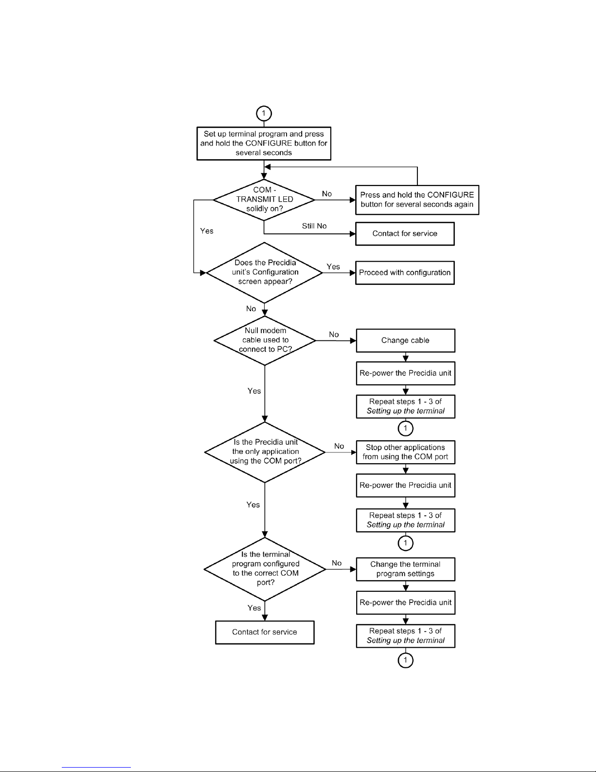
Appendix B: Troubleshooting and Support iPocket232 User Guide
Troubleshooting Configuration Access
B-2 Precidia Technologies Inc. 23-CML000293
Troubleshooting Flow for Set-Up Connection
Page 81

iPocket232 User Guide Appendix B: Troubleshooting and Support
Check IP Address (Ping)
Use ping to check if the iPocket232 is correctly configured on the network. If you
cannot reach the iPocket232 using Ping, the iPocket232 is either incorrectly
configured or there is a network problem.
To “ping” the iPocket232:
1 Open the MS-DOS Prompt. (Usually found under Start>Programs)
2 At the C:\WINDOWS> prompt type ping and the IP address you want to
check.
- If you get Reply messages, the iPocket232 has a valid connection to the
network.
- If you get a Request timed out message, the iPocket232 is incorrectly
configured with the IP address, or you have a network connection
problem.
NOTE: You can also use ping to check if an IP address is already in use on your
network, before assigning it to a new unit.
Basic Troubleshooting
Table B.1: Basic Troubleshooting
Problem Solution
The Configuration screen does not
appear when I press the CONFIGURE
button
I can’t access the unit using telnet 1 Ensure the unit is active on the network (check
I only see strange characters in the terminal window when I press the CONFIGURE button
1 Follow the troubleshooting flow diagram on the
previous page (B-2).
2 Ensure your terminal software is set to 9600 bps
3 Ensure you are pressing and holding the CON-
FIGURE button for at least 2 seconds
by pinging or viewing the status page locally)
2 Set a Remote Password
Ensure the terminal software is set to 9600 bps.
23-CML000293 Precidia Technologies Inc. B-3
Page 82

Appendix B: Troubleshooting and Support iPocket232 User Guide
Table B.1: Basic Troubleshooting
Problem Solution
The TRANSMIT lamp illuminates but
nothing appears on the terminal screen
when I press the CONFIGURE button
I completed set-up with 2 units, but
they do not appear to be communicating
I’m trying to connect my serial device to
my PC over the LAN/WAN
What are the pinouts for the unit? See “Connector Pinouts” on page E-1.
1 Check the terminal settings. Ideal settings are
9600 bps, 8 data bits, no parity, 1 stop bit, hardware flow control
2 Check that the terminal is configured to the cor-
rect Com port on your PC
3 Check that you are using a null modem cable to
connect the unit to your PC
4 Unplug the unit and plug it back in
5 Try again
1 Ensure IP Address, Subnet Mask, and Gateway
are configured or automatically obtained
2 Ensure the Local Port setting on each unit
matches the Remote Port on the other unit
You need to use Com Port Redirector software on
your PC and the ComPort Control Connection Con-
trol setting for the
iPocket232.
The unit is not connecting to the network
The unit is not communicating with the
serial device
I lost the Console Password and I cannot
access Configuration
The unit is not responding on the network.
Ensure the IP Address, Subnet Mask, and Gateway
are correctly configured. This can be done manually, or through a DHCP server.
1 Ensure all cables are properly connected
2 Ensure the proper cable is used.
3 Ensure you have a configured a Protocol for the
Serial Port and any other necessary settings
1 If you have defined a Remote Password, access
the unit through telnet and view or change the
Console Password
2 See page 14 of the User Guide for instructions on
how to reset the entire configuration to factory
default settings, erasing all passwords
Check that your cable length falls within the standards
set out in IEEE 802.3. For 10BaseT cables, the maximum distance that the cable can travel, before signal
degradation occurs, is 328 feet / 100 meters.
B-4 Precidia Technologies Inc. 23-CML000293
Page 83

iPocket232 User Guide Appendix B: Troubleshooting and Support
Table B.1: Basic Troubleshooting
Problem Solution
I lost the Console Password and I cannot
access Configuration
I lost the Console Password and I cannot
access Configuration
Indicator Lamps (LEDs)
ETHERNET – LINK lamp
Illuminates when the Ethernet port has a 10BaseT Ethernet network connection.
Table B.2: LINK Lamp Troubleshooting
1 If you have defined a Remote Password, access
the unit through telnet and view or change the
Console Password
2 See page 14 of the User Guide for instructions on
how to reset the entire configuration to factory
default settings, erasing all passwords
1 If you have defined a Remote Password, access
the unit through telnet and view or change the
Console Password
2 See page 14 of the User Guide for instructions on
how to reset the entire configuration to factory
default settings, erasing all passwords
Lamp Status Standard Troubleshooting Procedure
On OK - Ethernet
connection in
place
None
NOTE: This light may be on if the iPocket232 is
not configured.
Off No Ethernet
connection
• Ensure the Ethernet cable is properly plugged
into the iPocket232.
• Ensure the Ethernet cable's opposite end is
properly plugged into your LAN hub.
NOTE: The hub also has Link lamps that will
provide further troubleshooting information.
23-CML000293 Precidia Technologies Inc. B-5
Page 84

Appendix B: Troubleshooting and Support iPocket232 User Guide
ETHERNET – TRANSMIT lamp
Flashes when the iPocket232 is sending or receiving data via the Ethernet port.
Normally you will see very short data bursts.
Table B.3: TRANSMIT Lamp Troubleshooting
Lamp Status Standard Troubleshooting Procedure
Flashing
Off No data is
OK - data is
being transmitted
being transmitted
None
Ensure the Ethernet cable between the iPocket232
and the Ethernet device is properly connected
SERIAL – TRANSMIT lamp
Illuminates when the iPocket232 is sending or receiving data via the serial port
Normally you will see very short data bursts.
Table B.4: SERIAL TRANSMIT Lamp Troubleshooting
Lamp Status Standard Troubleshooting Practice
On OK - In config-
uration mode
Flashing
OK - data is
being transmitted
Finish configuring the iPocket232 and exit
from configuration mode.
None
Off No data is
B-6 Precidia Technologies Inc. 23-CML000293
being transmitted
• Ensure the serial cable between the
iPocket232 and the serial device is properly connected
• Was the configuration recently changed?
Look at the System Status page to check
the system uptime. If it is a short period,
check the configuration of the iPocket232
to see if it has been modified recently.
Please refer to Sections 3 and 4 for further
information.
Page 85

iPocket232 User Guide Appendix B: Troubleshooting and Support
SERIAL – STATUS lamp
This lamp indicates the status of the network connection.
Table B.5: SERIAL STATUS Lamp Troubleshooting
Lamp Status Standard Troubleshooting Practice
On Network connec-
tion is established
Slow
Flash
Fast
Flash
Off Unit may be
OK - no activity
present
OK - attempting
connection to
remote host
incorrectly
connected or
configured
Service and Support
Fill out the Service Request Form at
http://www.precidia.com/support/service_request.html
and a support representative will contact you within one business day.
General information, User Guides and Help Guides available at
None
None
None
• Ensure cable between the iPocket232
and the RS-232 device is properly
connected with the correct serial cable
• Check configuration of unit
http://www.precidia.com/
See Appendix C, Specifications and Warranty, for warranty information.
23-CML000293 Precidia Technologies Inc. B-7
Page 86

Appendix B: Troubleshooting and Support iPocket232 User Guide
B-8 Precidia Technologies Inc. 23-CML000293
Page 87

Appendix C:Specifications and
Warranty
iPocket232 Specifications
Serial interface:
Serial connector:
Serial speed:
Device support:
Ethernet interface:
Ethernet connector:
Ethernet speed:
Indicators:
Protocols/Services:
Configuration:
Security:
RS-232 DCE Interface
DB-9 female
300 – 115 200 bps
RS-232 asynchronous serial devices with 7- or 8-bit data, with or
w/out parity
Ethernet, IEEE 802.3, 10baseT
RJ-45
10 Mbps
Ethernet (link, transmit), Serial (transmit, status)
ARP, ICMP, UDP, TCP, IP, HTTP, telnet, TFTP, Com Port Control
(RFC2217), SNMPv2c, FTP, IPsec (manually keyed)
Serial interface protocol and IP addresses for device, subnet mask,
gateway router, and destination
IPsec (manually keyed), and Web, Remote and Console password protection
Power adapter:
Operating temp.:
Dimensions (l x w x h):
Weight:
23-CML000293 Precidia Technologies Inc. C-1
9V DC external, 300mA (power req. 8.5V, 200mA)
0-50ºC / 32-125ºF
85 mm x 45 mm x 24 mm / 3.33” x 1.75” x 0.95”
55 g / 1.94 oz.
285 g / 10.05 oz. (incl. power supply)
Page 88

Appendix C: Specifications and Warranty iPocket232 User Guide
Warranty
Precidia products are warranted against manufacturing defects in materials and
workmanship for a period of one year. This warranty is conditional on the unit
being installed and used as directed in the User Guide. The warranty is extended
to cover the iPocket232 as well as the power adapter.
Precidia's obligation under this warranty shall be limited to the repair, including
all necessary parts and the cost of labour connected therewith, or at our option the
exchange of a unit, which shows manufacturing defect within the warranty
period with a like new unit.
Customer obligations
The customer is responsible for transportation to the service depot and any applicable brokerage fees.
Warranty exclusions
This warranty shall not apply to appearance or any accessory items including but
not limited to cables. This warranty shall, in addition, not apply to damages due
to handling, transportation, and unpacking. The warranty also does not extend to
cover any malfunction caused by, or resulting from, abnormal environmental
conditions, unauthorized service, improper maintenance, modifications or repairs
by the customer, abuse, misuse, neglect, accident, fire, flood, or other acts of
nature, or incorrect line voltage.
The customer may have other rights under existing state/provincial or federal
laws, and where such laws prohibit any terms of this warranty, they are deemed
null and void, but the remainder of the warranty shall remain in effect.
Service and Support
Fill out a service request form at:
http://www.precidia.com/support/service_request.html
and a support representative will contact you within one business day.
General information, user guides and help guides available at
www.precidia.com
C-2 Precidia Technologies Inc. 23-CML000293
Page 89
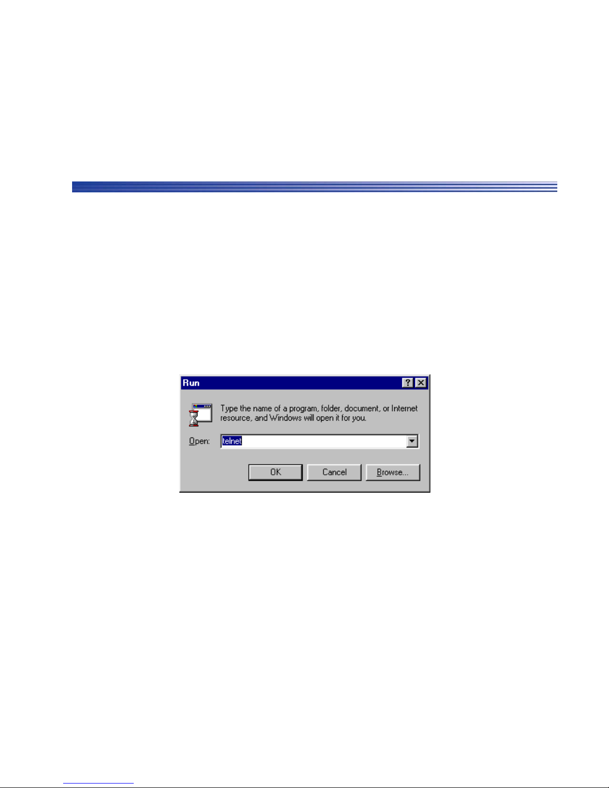
Appendix D:Connecting with Telnet
Before you can access and reconfigure Precidia products remotely, you must
configure the following settings locally:
• the IP Address and Subnet Mask (or automatically with DHCP)
• the Gateway address if necessary (or automatically with DHCP)
• the Remote Password
Refer to the User Guide for more information on configuring these settings.
To connect to the iPocket232 remotely using Telnet:
1 From the Start menu, select Run...
The Run window appears.
2 Type
The Telnet application window appears.
23-CML000293 Precidia Technologies Inc. D-1
telnet in the Open field and click OK.
Page 90
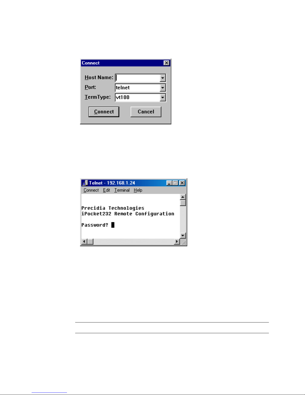
Appendix D: Connecting with Telnet iPocket232 User Guide
3 From the Connect menu, chose Remote Systems...
The Connect window appears.
4 Type the IP address of the unit in the Host Name field, and choose Telnet in
the Port field.
5 Click Connect.
You are prompted to enter your password in the Telnet window.
6 Type the
Remote Password you created during local configuration, and
press Enter.
The Configuration screen appears in the Telnet window.
If you typed an invalid password, the connection to the host will be dropped.
Ensure you have the correct IP address and Remote Password, and go back to
Step 3.
NOTE: The Remote Password is case sensitive.
D-2 Precidia Technologies Inc. 23-CML000293
Page 91

Appendix E:Pinouts and Power
Supply
Connector Pinouts
Straight Through Modem Serial Cable
DB-9 Male DB-9 Female
11
22
33
44
55
66
77
88
Serial Port Pinout (DB-9 Female)
Pin Signal Type
1 Data Carrier Detect (DCD) Out
2 Transmit Data (TD) Out
3 Receive Data (RD) In
4 Data Terminal Ready (DTR) In
5 Signal Ground (GND) Power
6 Data Set Ready (DSR) Out
7 Request to Send (RTS) In
8Clear to Send (CTS) Out
9No Connect/Power Out
23-CML000293 Precidia Technologies Inc. E-1
Page 92
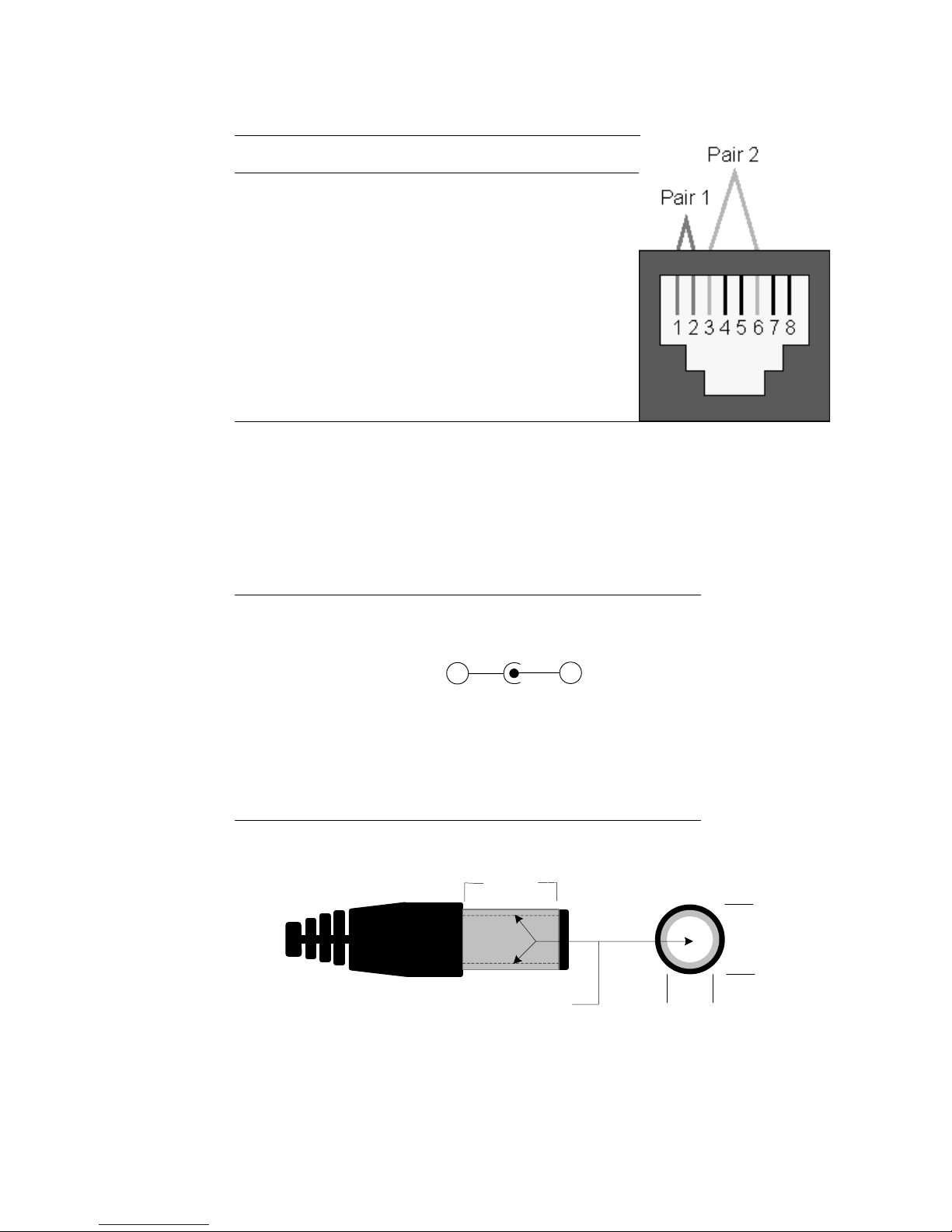
Appendix E: Pinouts and Power Supply iPocket232 User Guide
ETHERNET Port Pinout (RJ-45)
Pin Signal Type
1 Transmit positive (TX +) Out
2 Transmit negative (TX-) Out
3 Receive positive (RX+) In
4NC —
5NC —
6 Receive negative (RX-) In
7NC —
8NC —
Power Supply
Customers in North America are supplied with an AC power adapter conforming
to the specifications below. Customers in other parts of the world should obtain a
power supply that meets these requirements.
Output Voltage: 9 VDC @ 300 mA
Polarity: Center Pin Negative (-)
+
Inside Diameter: 2.1 mm
Outside Diameter: 5.5 mm
Barrel Length: 9.5 mm
Class 2 Transformer
9.5 mm
-
5.5 mm
E-2 Precidia Technologies Inc. 23-CML000293
Center Polarity: Negative (-)
2.1
mm
Page 93

Appendix F:MCC
Modem Connection Control is available with the Precidia’s Remote Access products. The iPocket232 is slightly different since it is a DCE device and drives the
DCD signal. When you choose
the iPocket232 behaves like a Hayes, or “universal” modem to the device
connected on its serial port. The connected serial device (DTE) receives the
expected modem replies when communicating with the iPocket232. For further
information on setting Modem Connection Control, see “Connection Control” on
page 27.
iPocket232 Modem Overview
AT commands direct a modem to dial, answer, hang-up, and perform many other
communication tasks. All commands listed, except A/ and +++, must be
preceded by AT, followed by a carriage return. You can include multiple
commands on a command line, as long as the command does not exceed 80 characters when including the prefix and carriage return. Spaces are ignored.
Commands following a command that opens, or closes an active connection, are
ignored.
Modem as the method of Connection Control,
A Dial command (ATD) instructs the modem to attempt a connection to the specified IP address and port number, or, if none is specified, to the configured
Remote IP in the Serial Port Settings sub-menu.
An On-Line command (ATO) instructs the modem to return to its active connection. If there is no active connection, the modem attempts to establish one using
the configured Remote IP and Remote Port.
An Answer command (ATA) instructs the modem to listen on a specified port
number. If no port number is specified, the configured local port number is used.
If the local port is not set, the standard telnet port (23) is used.
The escape sequence (+++) causes the modem to return to command mode from
answer or dial states, keeping the active connection open. An on-off transmission
on the DTR line also causes the modem to return to command mode. In this case,
the active connection may be maintained or closed, depending on how AT&D2 is
defined.
23-CML000293 Precidia Technologies Inc. F-1
Page 94

Appendix F: MCC iPocket232 User Guide
The modem must be in command mode to receive commands. Any command,
other than the escape sequence (+++), that is sent to the modem while it is in
transmission mode, is transmitted as data.
NOTE: If any characters arrive from the DTE while the modem is executing a
command, such as ATA or ATD, that command is aborted.
Supported AT Commands
Precidia supports a subset of the standard Hayes command set, and a selection of
extended commands, including the ability to initiate and perform FTP and HTTP
transfers (see page F-10).
NOTE: You can test the iPocket232 modem, when not in configuration mode, by
typing AT commands in your terminal software (HyperTerminal, Procomm Plus).
NOTE: Only the options listed under Parameters are valid. Any unsupported
standard command options return an OK result. Any unsupported non-standard
commands return an error result. Options not required are ignored.
The following two tables describe the supported standard AT commands and the
extended AT& and AT+ commands:
F-2 Precidia Technologies Inc. 23-CML000293
Page 95

iPocket232 User Guide Appendix F: MCC
Table F.1: Supported Commands
Command
Syntax
A[pppp] ANSWER
Description Parameters
Allows the iPocket232 modem to listen for a connection, or accept a connection on the provided port
[pppp].
Successful connection returns a “CONNECT
<speed>” message. Otherwise, the modem waits
indefinitely, or until a key is pressed to cancel.
If no port number is specified, the modem uses the
configured Local Port. If Local Port is 0, the modem
uses the standard telnet port (23).
The modem provides a “RING” message when an
incoming connection is received and auto-answer is
not active.
NOTE: A telnet program is already listening on port
23 if the Remote Password has been set. If this
command is also input, you will get an “ERROR”
message.
[pppp]
The listening port number,
range 0-65535
Dstring DIAL
Attempts a connection to the specified IP address.
If the IP is specified, but port is not, the modem uses
the telnet port (23).
If a dial string is invalid or not specified, the modem
uses the Remote IP and Remote Port.
If Remote Port is 0, the modem uses the Fallback IP
and Fallback Port.
DS=n or
DSn
DIAL STORED
Attempts a connection to a stored IP address and port
number.
En ECHO
Allows host commands to be echoed.
string =
aaa.bbb.ccc.ddd:pppp
aaa.bbb.ccc.ddd is the IP
address in standard notation
pppp is the port number (0-
65535)
Note: Any non-digit can
replace the “.” or “:”.
n = 0 (or no option present)
uses Remote location
n = 1 uses Fallback loca-
tion
n = 0 (or no option present)
will disable echo
n =1 enables command
mode echo (default)
23-CML000293 Precidia Technologies Inc. F-3
Page 96

Appendix F: MCC iPocket232 User Guide
Table F.1: Supported Commands
Command
Syntax
Hn HOOK
In INQUIRY
Description Parameters
n = 0 (or no option present)
Closes an open connection.
will close an open
connection.
n = 0 returns the product
Displays information about the iPocket232.
name
n = 1 returns the product
name, the company
name, version string
and Device ID
n = 2 returns the informa-
tion listed above,
plus the IP addresses
for device information, status, log history, company
information and support.
O ONLINE (Go on-line)
Will return to an active connection if one exists
(escaped from via the "+++" command) or originate a
connection to the configured Remote host.
Qn RESULT CODES DISPLAY
Allows you to choose whether result codes are displayed after each command.
Sr=n SET REGISTER
Set value of register r to n.
Sr?DISPLAY REGISTER
Inquiry about value of register r.
none
n = 0 (or no option present)
returns result codes
n = 1 will not return result
codes
r = register number
Note: r cannot be greater
than 14. Register S13
is reserved. See , SRegisters‚ on
page 8..
n = value to assign
r = register number
F-4 Precidia Technologies Inc. 23-CML000293
Page 97

iPocket232 User Guide Appendix F: MCC
Table F.1: Supported Commands
Command
Syntax
Vn RESULT CODES FORMAT
Description Parameters
Choose how result codes are returned.
Z RESET
Closes any active connection and resets the S-registers to their saved values.
Table F.2: Extended AT& and AT+ Commands
Command
Syntax
&Cn DCD CONTROL
Description Parameters
Controls the behavior of the DCD line.
n = 0 (or no option present)
displays result codes
in numeric form
n = 1 displays result codes
in verbose (text)
form (default)
none
n = 0 sets the DCD line as always
active
n = 1 sets the DCD line to follow
the connection status
(default)
&Dn DTR CONTROL
Sets how the iPocket232 will react to changes
in the DTR signal.
&F LOAD FACTORY SETTINGS
Loads the default settings for commands and
S- registers.
n = 0 ignore
n = 1 DTR on-off transition returns
modem to command mode
and maintains the connection
n = 2 DTR on-off transition returns
modem to command mode
and closes the connection
(default)
n = 3 on-off transition returns the
modem to command mode,
closes the connection, and
resets the S-registers and
command options to saved
values (as with ATZ)
none
23-CML000293 Precidia Technologies Inc. F-5
Page 98

Appendix F: MCC iPocket232 User Guide
Table F.2: Extended AT& and AT+ Commands
Command
Syntax
&Hn FLOW CONTROL
Description Parameters
Sets the type of flow control used. The default
is set in configuration.
&Sn DSR CONTROL
Sets how the modem drives the DSR signal.
&V VIEW PROFILE SETTINGS
Displays the command and S-register settings.
&W SAVE CONFIG
Writes the current configuration settings into
memory. Includes the S-register values, command options, IP addresses and port numbers.
n = 0 disables flow control
n = 1 selects hardware (CTS/
RTS) flow control
n = 2 selects software (XON/
XFF) flow control
n = 0 (or no option present) sets
the DSR line as always
active (default)
n = 1 sets the DSR line to follow
the connection status
none
none
&Z? DISPLAY NUMBERS
Returns the currently configured Remote IP
and Remote Port as “Stored Host #1:
xxx.xxx.xxx.xxx:pppp
and Fallback Port as “Stored Host #2:
xxx.xxx.xxx.xxx:pppp
&Zn=s STORE NUMBER
Stores an IP address and port number (in the
form xxx.xxx.xxx.xxx:pppp) into either the
Remote IP and Port or Fallback IP and Port
locations.
none
” and the Fallback IP
”.
n = 0 Stores as Remote IP and Port
(primary location)
n = 1 Stores as Fallback IP and
Port
F-6 Precidia Technologies Inc. 23-CML000293
Page 99

iPocket232 User Guide Appendix F: MCC
Table F.2: Extended AT& and AT+ Commands
Command
Syntax
+Bn FALLBACK HOST
Description Parameters
Enables or disables switchover to a fallback
host in case of primary host connection failure.
An ATD command always attempts a connection with the Remote IP (primary host). If
FallBack IP is configured and enabled, upon
failure to connect with the Remote IP the next
ATD command attempts a connection with the
Fallback IP. Regardless of whether a connection is established, the next ATD command reattempts a connection to the Remote IP.
+Hn NETWORK CONTROL
NOTE: For IP232 and Cell 232Plus only.
Establishes or drops PPP connections to the
configured host.
n=0 Disables switchover to fall-
back host.
n=1 Enables switchover to fall-
back host.
n = 0 (or no option present) Termi-
nates PPP connection
n = 1 Establishes PPP connection
+Pstring FTP PUT / HTTP PUT
Upload from Precidia modem to an FTP or
HTTP server.*
+Gstring FTP GET / HTTP GET
Download from an FTP or HTTP server to the
Precidia modem.*
* See page 9 for a description of FTP/HTTP procedures.
Escape to Command Mode
The modem can be moved into command mode in one of two ways: sending the
sequence (pause, +++, pause) to the serial port, or dropping the DTR signal
(AT&Dn).
The first method, sending an escape sequence, moves the modem into command
mode but keeps the connection active. The default escape character is “+” and is
stored in register S2. The default pause value is the value of register S12 (20)
multiplied by 20ms. You can change the defaults by setting the registers with
your own values.
string =
ftp://[userid[:password]@]ipadr[:port]/path/file.ext
string =
ftp://[userid[:password]@]ipadr[:port]/path/file.ext
23-CML000293 Precidia Technologies Inc. F-7
Page 100

Appendix F: MCC iPocket232 User Guide
The second method, dropping the DTR signal, is not supported by hardware platforms that do not have a wire for the DTR signal. Additionally, the reaction to the
DTR signal depends on how you configure the DTR setting using the &Dn
command. See &Dn on page E-4 for DTR settings.
S-Registers
Basic S-registers (S0–S12) store information used by the modem and communication software. Basic S-registers have predefined values. Extended S-registers
(S13+) are used for storing command option values. The following table summarizes the values and purpose of Precidia-supported S-registers.
Table F.3: Precidia S-Register Definitions
“S”
Register
00
10
243
313
410
58
63
760
82
96
10 7
Default
(decimal)
Purpose
Zero value disables auto-answer. Any non-zero
value enables auto-answer.
Unused.
Defines escape character. (+)
Defines carriage return. Cannot be changed.
Defines line feed. Cannot be changed.
Defines backspace.
Unused.
Unused.
Unused.
Unused.
Unused.
11 70
12 50
13 —
14 3
F-8 Precidia Technologies Inc. 23-CML000293
Unused.
Defines guard time in 20 ms increments.
Reserved.
FTP/HTTP timeout in seconds to a maximum of 60.
 Loading...