

PRAXSYM PAMS User Manual
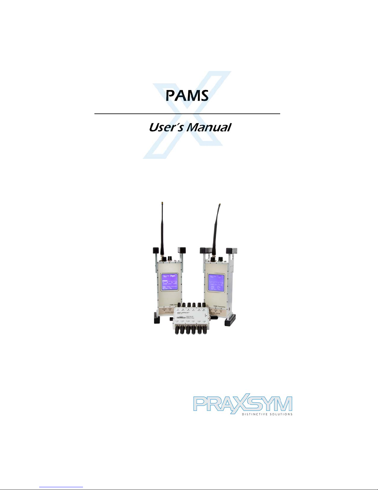
PAMS
Portable Attenuation Measurement System
User’s Manual
The solution for making easy shielding effectiveness
measurements.
310-010042-001

TABLE OF CONTENTS
Warranty Statement 1
Chapter 1 General Information 2
Introduction
Equipment Purpose
Equipment List
Specifications
Chapter 2 System Care 5
Transportation
Recharging
Safety/Handling
Equipment Service
Chapter 3 Operation 7
Describes operational sequences necessary
to perform required certification and verification
3.1 Receiver
3.2 Transmitter
3.3 Making Shield Level Measurements
3.4 Using Broadband Mode
3.5 Monitor Mode operational sequence
3.6 Audio Threshold/Tone Usage
Warranty Statement
PRAXSYM warrants that all items will be free from defects in material and workmanship under use as
specified in this guide for a period of one year from date of delivery. PRAXSYM further agrees to repair
or replace, at its discretion, any failure which upon PRAXSYM's inspection appears to be a result of
workmanship or material defect. In no case, shall PRAXSYM's liability for breach of warranty exceed the
purchase price of the items in question. PRAXSYM's liability on any claim of any kind, for any loss
connected with, or resulting from the use of, performance or breach thereof, installation, inspection,
operation or use of any equipment furnished by PRAXSYM, shall in no case exceed the purchase price of
the goods which give rise to the claim.
Praxsym, Inc. 120 S. Third St. Fisher, IL 61843
217-897-1744 www.praxsym.com
Page 1

PRAXSYM
Chapter 1 General Information
Introduction
The Portable Attenuation Measurement System (PAMS) is designed
to measure the shielding effectiveness of RF enclosures. PAMS is a
tool specifically engineered to enable regular maintenance of RF
Shielded Enclosures. Routine measurements can be made to ensure
a baseline shield level is maintained with minimal disruption to
normal activities of the enclosure.
Equipment Purpose
The PAMS measures the shielding effectiveness of RF enclosures.
Both bar graph and numeric readout display the shielding level (dB).
Separately, the transmitter and receiver will also work well in custom
applications. The transmitter provides a portable and semi-rugged
CW transmitter with adjustable output power up to 1 Watt in the
frequency range from 864 MHz to 936 MHz. The receiver’s features
allow it to make accurate signal level measurements in the presence
of high ambient wireless energy over a large dynamic range and as
low as -120 dBm.
Equipment List
Transmitter
Receiver
Rechargeable Battery Packs (2 each, one installed per unit)
AC/DC power supply with cord, 15 VDC @ 3.4A (2 each)
32 Ω headphone set
12 position coax RF switch
6’ BNC/BNC RF (50 Ω ) cable
Antennas, extended 1/4 wavelength (2 each)
Transit Case
User’s Manual
Page 2

PAMS Receiver Specifications
Frequency 864-936 MHz
Channel Spacing 100 kHz
Detection Mode CW
Measurement Range -120dBm to 0 dBm
Measurement Accuracy +/-2 dB (-110 to 0 dBm)
Frequency Stability +/- 2.5 ppm
Charge Voltage at Power Jack DC, 15 +/-1.0 V @ 2A
Battery Operation 4 hours operation
70 minutes charge
Controls OFF/VOL, MODE, CAL,
FREQUENCY SELECT
T’HOLD UP/DOWN,
LOCK, BACK LIGHT
Indicators MODE, CAL STATUS,
SIGNAL LEVEL,
FREQUENCY, LOCK
THRESHOLD SETTING,
BATTERY CHARGE
User Interface Full Alpha-numeric Backlit
LCD display
Operating Temperature 0°C to 40°C
Weight 5.5 lbs.
Size 11.7” H x 5.1” D x 4.9” W
Headphone Impedance 32 Ω
Page 3

PRAXSYM
PAMS Transmitter Specifications
Frequency 864-936 MHz
Channel Spacing 100 kHz
Operating Modes CW, BROADBAND
CW Output Power -30 dBm to +30 dB (CW)
Broadband Output Combline with pickets at
25 MHz steps from 750 1000 MHz, -12dBm
Attenuation 0 to 60 dBm
1, 2, or 5 dB steps
Frequency Stability +/-2.5 ppm
Charge Voltage at Power Jack DC, 15 +/-1.0 V @ 2A
Battery Operation 2 hours operation
70 minutes charge
Controls OFF/ON, MODE, ATTEN
FREQUENCY SELECT,
BACK LIGHT, LOCK
Indicators MODE, FREQUENCY,
OUTPUT POWER,
ATTEN LEVEL,LOCK,
BATTERY CHARGE
User Interface Full Alpha-numeric Back lit LCD display
Operating Temperature 0°C to 40°C
Weight 5.5 lbs.
Size 11.7” H x 5.1” D x 4.9” W
Page 4

Chapter 2 System Care
Transportation
The PAMS is normally shipped (and transported) in a shock resistant
transfer case. Batteries for the transmitter and receiver are contained
inside the respective units.
Recharging the PAMS Units
To charge the battery pack inside the PAMS unit, plug the 2.5mm
female connector of the AC/DC 15 V power pack into the power
receptacle on the right side of the PAMS Transmitter or Receiver.
Plug the charger line cord into an AC source (95-250 VAC, 47-63 Hz).
The green CHARGE light on the front face of the PAMS unit should
illuminate during the entire fast charge cycle. The fast charge cycle
of a discharged battery will normally take less than 1.5 hours. When
the unit is fully charged, the CHARGE light will begin flashing
indicating the trickle charge phase. The trickle charger will continue
to top-off the battery pack until the AC/DC power pack is
disconnected. Although this top-off process is normally completed in
less than 6 hours, it can be left on overnight.
The battery may self-discharge to less than 3 Volts after a period of
storage or if the unit is left on for several days. During a new charge
cycle it will first enter a pre-charge trickle state before beginning the
fast charge phase. The green CHARGE light will flash during this
phase and then stay on continually once the fast charge phase has
begun. The pre-charge trickle phase can take anywhere form a few
seconds to 60 minutes dependent on the initial charge state. If the
fast charge state has not begun after several hours, the battery pack
should be replaced.
If a charge cycle is initiated on a fully charged battery, it is possible
that it will not be able to complete a normal charging cycle,
illuminating the FAULT light. Although the FAULT light indicates
that the charge cycle was terminated, the trickle charge will continue
to top-off the battery pack and it does not indicate a failure.
The FAULT light indicates that the charge process has been
terminated. A FAULT light will be indicated with:
1. Excess supply input voltage
2. Very low battery voltage (indicate shorted cells)
3. Battery voltage low after 1/12th of charge timer
4. The charge is not normally terminated before the end of the
cycle timer
Page 5
 Loading...