

Pratissoli VF 12, VF 14, VF Series Use And Maintenance Manual
VF
Menu
VF Series
Use and Maintenance
Manual
1

VF
INDEX
1. INTRODUCTION 4
2. SYMBOL DESCRIPTION 4
3. SAFETY 5
3.1 General safety indications....................................................................................................5
3.2 High pressure unit safety requirements................................................................................5
3.3 Safety during operation........................................................................................................5
3.4 General procedures for using nozzles..................................................................................5
3.5 Safety during unit maintenance ...........................................................................................6
4. PUMP IDENTIFICATION 6
5. TECHNICAL CHARACTERISTICS 7
6. DIMENSIONS AND WEIGHT 7
7. INFORMATION REGARDING PUMP USE 8
7.1 Water temperature................................................................................................................8
7. 2 Maximum flow rate and pressure values............................................................................8
7. 3 Lowest rpm.........................................................................................................................8
7.4 Recommended lubricant oil types and Manufactures..........................................................9
8. PORTS AND CONNECTIONS 11
8.1 Conic sealing pads.............................................................................................................11
9. PUMP INSTALLATION 12
9.1 Installation .........................................................................................................................12
9.2 Sense of rotation................................................................................................................13
9.3 Version change ..................................................................................................................13
9.4 Hydraulic Connections.......................................................................................................14
9.5 Pump feeding.....................................................................................................................14
9.6 Suction line........................................................................................................................14
9.7 Filtering..............................................................................................................................15
9.8 Delivery line ......................................................................................................................15
9.9 Internal diameter of the pipeline........................................................................................16
9.10 V-belt transmission..........................................................................................................17
9.11 Transmission definition ...................................................................................................17
9.12 Definition of belt static tension values.............................................................................19
10. START-UP AND OPERATION 21
10.1 Preliminary Inspections ...................................................................................................21
10.2 Start-up ............................................................................................................................21
10.3 Seal packing cooling circuit.............................................................................................22
11. PREVENTIVE MAINTENANCE 22
12. STOPPING THE PUMP FOR LONG PERIODS 24
12.1 Inactivity for long periods................................................................................................24
12.2 Filling the pump with an anti-corrosion emulsion or anti-freeze solution.......................24
12.3 Pipes.................................................................................................................................24
13. PRECAUTIONS AGAINST FREEZING 24
14. WARRANTY TERMS 24
2

VF
15. TROUBLESHOOTING 25
16. EXPLODED VIEW AND PART LIST 26
3
VF
1. INTRODUCTION
This manual describes the use and maintenance instructions of the VF pump, and should be carefully read
and understood before using the pump.
Correct use and adequate maintenance will guarantee the pump’s trouble-free operation for a long time.
The Interpump Group declines any responsibility for damage caused by misuse or the non-observance of the
instructions indicated in this manual.
Upon receiving the pump, check that it is complete and in perfect conditions.
Should anything be found out of order, please contact us before installing and starting the pump.
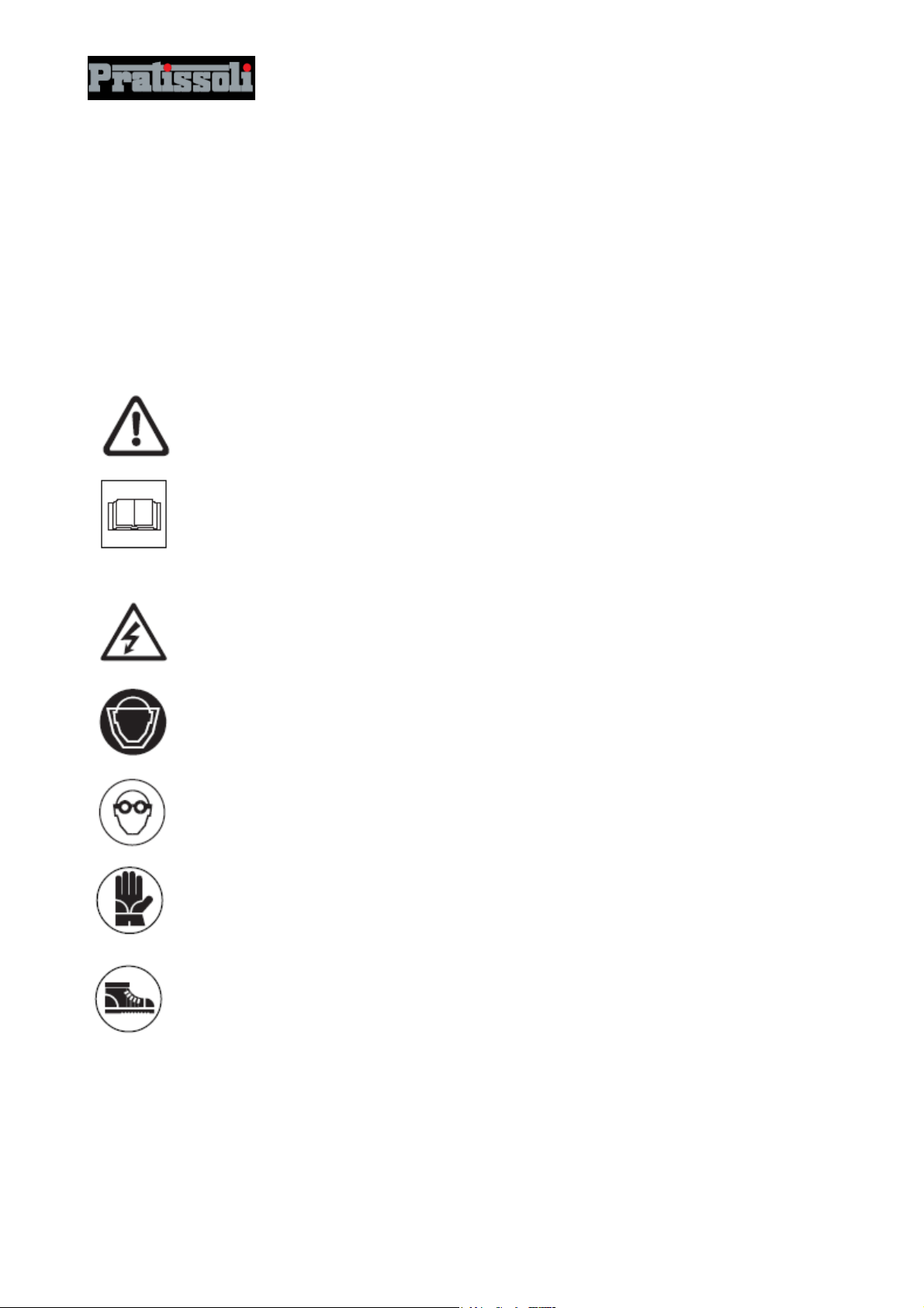
2. SYMBOL DESCRIPTION
Carefully read the indications in this
manual before operating the pump.
Warning Signal
Danger Signal
Electrocution danger
Danger Signal
Use face guard
Danger Signal
Use protective glasses
Danger Signal
Use adequate hand protection before
operating the pump
Danger Signal
Use appropriate boots
4
VF
3. SAFETY
3.1 General safety indications
The misuse of pumps and high pressure units, and the non-observance of installation and maintenance
instructions may cause severe injury to people and/or damage to property. Anyone requested to assemble or
use high pressure units must possess the necessary competence to do so, should be aware of the
characteristics of the components assembled/used, and must adopt all the necessary precautions in order to
guarantee maximum safety in any operating condition. In the interest of safety, no precaution that is
reasonably feasible must be neglected, both by the Manufacturer and the Operator.
3.2 High pressure unit safety requirements
1. The pressure line must always be equipped with a safety valve.
2. High pressure unit components, in particular for those units working outside, must be adequately
protected against rain, frost and heat.
3. The unit’s electrical parts must be adequately protected from water spray, and must comply with the
specific norms in force.
4. High pressure pipes must be correctly sized for the unit’s maximum operating pressure, and must only be
used within the pressure range indicated by the pipe Manufacturer.
The same conditions apply for all other unit accessories where high pressure is involved.
5. The extremities of high pressure pipes must be sheathed and fastened to a steady structure in order to
avoid dangerous whiplashes should they burst or should their connections break.
6. Appropriate safety guards must be provided for the pump transmission systems (joints, pulleys and belts,
auxiliary drives).
3.3 Safety during operation
The working area of a high pressure system must be clearly signalled. Access must be prohibited to nonauthorised personnel and, if possible, the area must be fenced in. The personnel authorised to access this
area must be previously trained, and informed about the risks that may arise from failures or malfunctions of
the high pressure unit.
Before starting the unit, the Operator must check:
1. That the high pressure unit is correctly fed (see paragraph 9.5).
2. That Pump intake filters are perfectly clean; we advise to use a device that indicates the filter’s clogging
level.
3. That electrical parts are adequately protected and in perfect conditions.
4. That high pressure pipes do not show apparent signs of abrasion, and that fittings are in perfect shape.
Any anomaly or reasonable doubt that may arise before or during operation must be promptly reported, and
verified by competent personnel. In these cases, pressure must be immediately released and the high
pressure unit stopped.
3.4 General procedures for using nozzles
1. The Operator must always place his own and other worker’s safety before any other interest; his actions
should always be governed by good sense and responsibility.
2. The Operator must always wear a helmet with a protective visor, waterproof clothing, and appropriate
boots capable of guaranteeing grip on wet pavements.
Note: appropriate clothing will effectively protect against water spray, but it may not offer adequate protection
against the direct impact of water jets or sprays from a close distance. Some circumstances may req uire
further protection.
5
VF
3. We advise to employ a team of at least two Operators, able to provide mutual and immediate assistance if
needed, and rotate their duties in case of long and heavy work.
4. Access to the work area that is within the water jet’s range must be absolutely forbidden; the area must be
free of objects that may be unintentionally hit by the pressurised jet, causing damage or dangerous
situations.
5. The water jet must only and always be directed towards the work area, even during testing or preliminary
inspections.
6. The Operator must always pay attention to the trajectory of the debris removed by the water jet. If
necessary, adequate side guards must be provided by the Operator in order to protect anything that may
be accidentally exposed.
7. For no reason must the Operator be distracted during operation. The personnel that needs to access the
working area must wait for the Operator to suspend his work, and then immediately make his presence
known.
8. For safety reasons, it is important that each member of the team is perfectly aware of the intentions and
actions of other team members in order to avoid dangerous misunderstandings.
9. The high pressure unit must not be started and brought up to pressure unless each member of the team is
in his designated position, and the Operator has already directed the nozzle towards the work area.
3.5 Safety during unit maintenance
1. The maintenance of the high pressure unit must be done within the time intervals indicated by the
Manufacturer, who is responsible for the entire unit’s compliance with the norms in force.
2. Maintenance must always be carried out by specialised and authorised personnel.
3. Assembly and disassembly of the pump and its various components must be performed exclusively by
authorised personnel, using appropriate tools in order to avoid damage to components and connections.
4. To guarantee total reliability and safety, always use original spare parts.
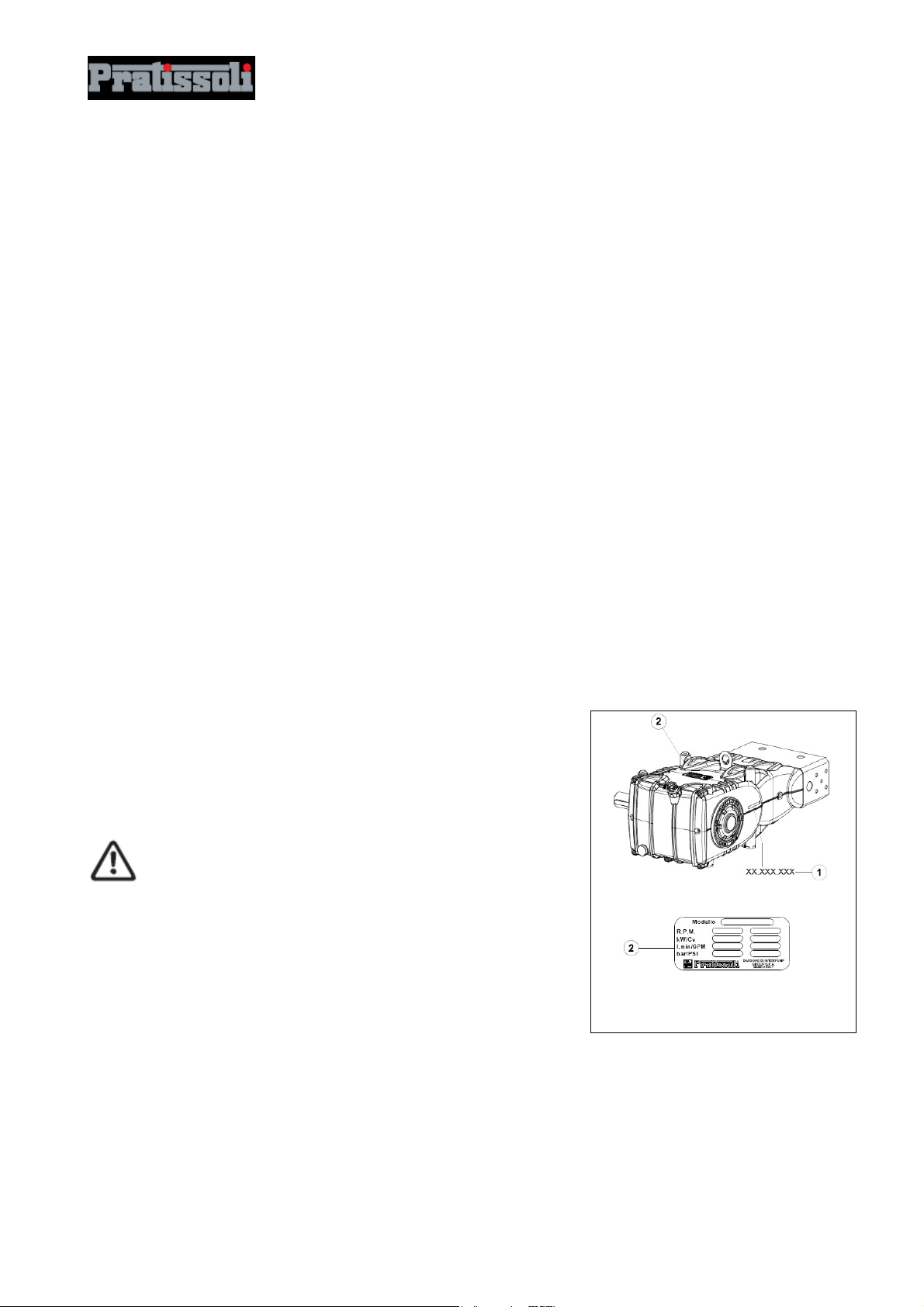
4. PUMP IDENTIFICATION
Each pump (fig. 1) has: its own serial number XX.XXX.XXX (see point c) and a rating plate (see point d)
that indicates:
Pump model and version
Maximum rpm
Power absorbed Hp - kW
Flow rate l/min - G.P.M
Pressure bar - P.S.I.
Pump model, version and serial number must always be
specified when ordering spare parts.
fig. 1
6

VF
5. TECHNICAL CHARACTERISTICS
Flow rate Pressure Power
Model RPM
l/min Gpm bar psi kW Hp
750 12.5 3.3 1500 21750 36.8 50
VF 12
900 15 4 1200 17500 36.8 50
750 17 4.5 1100 16000 36.8 50
VF 14
1000 23 6 800 11600 36.8 50
6. DIMENSIONS AND WEIGHT
For dimensions and weight of Standard Version pumps, please refer to fig. 2;
For dimensions and weight of pumps with type “A” Flange, please refer to fig. 2/a.
Weight - 60 Kg
Weight - 61 Kg
fig. 2
7
VF
fig. 2/a
7. INFORMATION REGARDING PUMP USE
The VF pump has been designed to operate with filtered water (see paragraph 9.7) and at room
temperature.
Other fluids may be used only upon the approval of the Technical Department or Customer
Assistance Service.
7.1 Water temperature
The maximum water temperature allowed is 30°C.
7. 2 Maximum flow rate and pressure values
The performance values indicated in the catalogue refer to the maximum performance of the pump.
Regardless of the power used, pressure and maximum rpm values indicated on the plate may not be
exceeded unless expressly authorised by the Technical Department or Customer Assistance Service.
7. 3 Lowest rpm
Any rpm value different from what indicated in the performance table (see chapter 5) must be expressly
authorised by the Technical Department or Customer Assistance Service.
8
VF
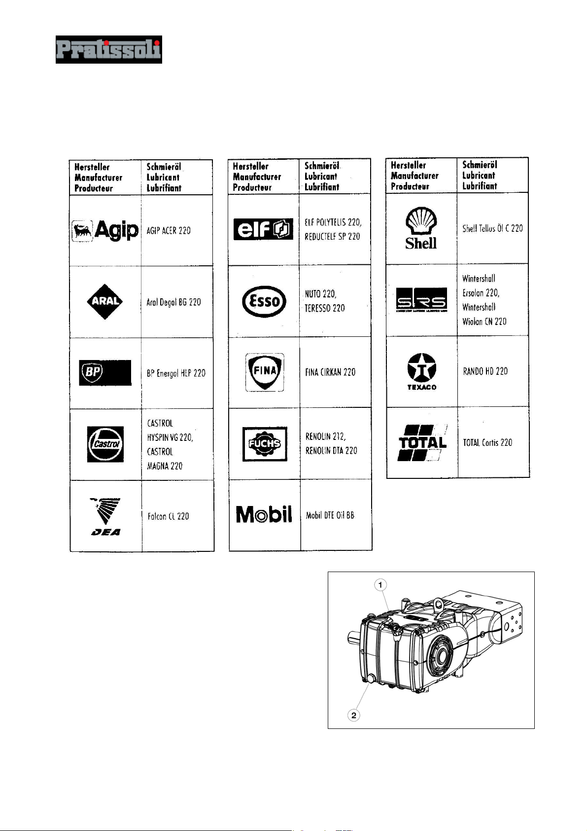
7.4 Recommended lubricant oil types and Manufactures
The pump is delivered with lubricant oil type Mobil DTE Oil BB (ISO VG 220), compliant with room
temperatures ranging between 0°C and 30°C.
Some recommended lubricant types are indicated in the table below; these lubricants are treated with
additives in order to increase corrosion protection and resistance to fatigue (according to DIN 51517 part 2).
As an alternative, Automotive SAE 85W-90 gearing lubricants may also be used.
Check the oil level by using the apposite oil level dipstick
with minimum and maximum value notches
needed.
Correct oil level inspection is done with the pump at room
temperature; oil is changed with the pump at working
temperature, by removing the rear plug
Oil is to be changed every 1000 hours of operation.
The amount required is ~3.8 litres.
c, fig.3. Refill if
d, fig.3.
9
fig. 3
 Loading...