

Pramac Zings maintenance Manual

Operation and maintenance Manual

CONTENT
PREFACE............................................................................................................................................................................4
1. SAFETY...........................................................................................................................................................................4
1.1 General..................................................................................................................................................................4
1.2 Installation, Handling, and Towing.....................................................................................................................4
1.3 Fires and Explosion.............................................................................................................................................5
1.4 Protection Enclosure ...........................................................................................................................................6
1.5 Chemical ...............................................................................................................................................................6
1.6 Noise......................................................................................................................................................................6
1.7 Electrical Devices ................................................................................................................................................6
1.8 First Aid For Electric Shock ................................................................................................................................7
WARNING ...................................................................................................................................................................8
2. GENERAL DESCRIPTION...........................................................................................................................................9
2.1 Generating Set Description and Identification.................................................................................................9
2.2 Diesel Engine .......................................................................................................................................................9
2.2.1 Engine Electrical System.........................................................................................................................9
2.2.2 Cooling System.......................................................................................................................................10
2.2.3 Silencers and Exhaust System.............................................................................................................10
2.3 Alternator.............................................................................................................................................................10
2.4 Control System (Identification).........................................................................................................................10
2.4.1 Output Circuit Breaker ...........................................................................................................................10
2.5 Fuel Tank and Base frame ...............................................................................................................................10
2.6 ATS Cabinet ........................................................................................................................................................10
3. INST
4. Debugging and Operation ..........................................................................................................................................21
ALLATION.........................................................................................................................................................11
3.1 General instruction ............................................................................................................................................11
3.2 Preparation before installation .........................................................................................................................11
3.2.1 Genset lifting ...........................................................................................................................................11
3.2.2 Case open check....................................................................................................................................12
3.2.3 Line and position ....................................................................................................................................12
3.2.4 Familiar with installation tools and hard wares .................................................................................. 12
3.3 Genset installation .............................................................................................................................................14
3.4 Auxiliary installation ...........................................................................................................................................14
3.4.1 Fuel refilling system installation............................................................................................................14
3.4.2 Exhaust system installation...................................................................................................................14
3.4.3 Ventilation and cooli
3.4.4 Battery start system ...............................................................................................................................15
3.4.5 Electric system connection ...................................................................................................................15
3.5 Outdoor canopy genset installation.................................................................................................................17
3.5.1 Genset installation..................................................................................................................................17
3.5.2 External fuel tank installation................................................................................................................17
3.5.3 ATS installation .......................................................................................................................................19
3.5.4 Cables layout ..........................................................................................................................................20
ng radiator ............................................................................................................15
1

4.1 Replenish qualified fuel, oil and coolant (suitable for water cooled genset) .............................................21
4.1.1 Fuel...........................................................................................................................................................21
4.1.2 Lubricant oil .............................................................................................................................................22
4.1.3 Coolant.....................................................................................................................................................23
4.2 Genset examination ..........................................................................................................................................23
4.2.1 Engine examination................................................................................................................................23
4.2.2 Alternator examination...........................................................................................................................23
4.3 Genset debugging .............................................................................................................................................24
4.3.1 Genset startup.........................................................................................................................................24
4.3.2 Non load eaamination............................................................................................................................24
4.3.3 Data configuration ..................................................................................................................................24
4.3.4 Take load step by step ...........................................................................................................................25
4.3.5 Genset stop .............................................................................................................................................25
4.3.6 Examine genset self protect functions ................................................................................................25
4.3.7 Test other functions................................................................................................................................25
5. Maintenance and Repair Instruction .........................................................................................................................26
5.1 General................................................................................................................................................................26
5.2 Common maintenance classification and period ..........................................................................................26
5.3 Maintenance content.........................................................................................................................................26
5.3.1 Class A maintenance .............................................................................................................................26
5.3.2 Class B maintenance.............................................................................................................................27
5.3.3 Class C maintenance.............................................................................................................................27
5.3.4 Class D maintenance.............................................................................................................................27
5.3.5 Seasonal maintenance ..........................................................................................................................27
5.4 Maintenance procedures ..................................................................................................................................28
5.5 Maintenance measures ....................................................................................................................................28
5.5.1 Air filter .....................................................................................................................................................28
5.5.2 Oil filter .....................................................................................................................................................29
5.5.3 Fuel filter ..................................................................................................................................................29
5.5.4 Coolant filter replacement (if configured)............................................................................................29
5.5.5 Lubricant oil replacement ......................................................................................................................30
5.5.6 Coolant replacement and water tank clean ........................................................................................30
5.5.7 Battery maintenance ..............................................................................................................................30
5.5.8 Alternator maintenance..........................................................................................................................31
5.6 Genset common fault troublesho
oting............................................................................................................31
6. ZK3201 Control panel manual ...................................................................................................................................33
6.1 general.................................................................................................................................................................33
6.2 Connection Port .................................................................................................................................................34
6.3 Operation Panel .................................................................................................................................................38
6.3.1 Preparations before operation......................................................................................................................38
6.3.2 The whole operation panel inc
ludes 3 sections: measuring parameter display by LED, operation
switch and running status LED indication.............................................................................................................38
6.3.3 LCD Display and Control Keys:....................................................................................................................39
6.3.4 Measuring data ...............................................................................................................................................41
6.4 System Parameter.............................................................................................................................................41
2

6.5 Alarm and Stop failure.......................................................................................................................................44
6.5.1 Alarm ................................................................................................................................................................44
6.5.2 Stop Failure .....................................................................................................................................................44
6.6 Communication Function..................................................................................................................................45
6.6.1 Brief Introduction ............................................................................................................................................45
6.6.2 CI485 Communication Connection..............................................................................................................45
6.6.3 Communication Protocol ...............................................................................................................................47
6.7 Troubleshooting..................................................................................................................................................53
3

PREFACE
This manual is designed for genset’s installation, debugging, operation, maintenance and repair. It should be used in
conjunction with the Engine Manual, and Alternator Manual. All documents should be laid down besides genset in order
to easy reading.
All specifications and marks are assembled in recent version, if there is any change won’t have notice. For easy
instruction, canopy, enclosure and baffle have been released.
Genset is designed for industrial use; it can be operated after refilling coolant, fuel and battery electrolyte. Experience
manufacturer makes sure to provide stable and reliable power sources. But pay much attention to genset maintenance if it’s
used in dirty or dusty environment.
All maintenance, debugging and repair should be done by experienced trainer.
1. SAFETY
1.1 General
The generating set is designed to be safe when used in the correct manner. Responsibility for safety, however, rests with
the personnel who install, use and maintain the set. The following safety precautions, if followed, will minimize the
possibility of accidents. Before performing any procedure or operating technique, it is up to the user to ensure that it is
safe. Personnel who are authorized and trained should only operate the generating set.
WARNING:
! Read and understand all safety warnings before operating or performing maintenance on the generating set.
! Failure to follow the instructions, procedures, and safety precautions in this manual may increase the possibility of
accidents and injuries.
! Never start the generating set unless it is safe to do.
! Do not attempt to operate the generating set with a known unsafe condition.
! If the generating set is unsafe, fit danger notices and disconnect the battery negative (-) lead so that it cannot be
started until the condition is corrected.
! Disconnect the battery negative (-) lead prior to attempting any repairs or cleaning inside the enclosure, if equipped.
! Install and operate this generating set only in full compliance with relevant National, Local, or Federal Codes,
Standards or other requirements.
1.2 Installation, Handling, and Towing
The following safety precautions should be noted:
! Make electrical cable earthling comply with local relevant Electrical requirements.
! For stationary gensets, the storage system must isolated from rain, dust or other corrosion chemicals installed in
comply with local Standards or other Standards whichever applicable
! Engine exhaust emission is detrimental to the health of personnel. The exhaust for all indoor generating sets must be
piped outdoors via leak-free piping in compliance with relevant Codes, Standards and other requirements. Ensure hot
exhaust silencers, piping and turbochargers, if equipped, are clear of combustible material and are guarded for
personnel protection per safety requirements. Ensure that fumes from the exhaust outlet will not be a hazard.
! Never lift the generating set by attaching to the engine or alternator lifting lugs. Use a sling with a 'spreader bar'
4

connected to the base frame.
! Ensure the lifting rigging and supporting structure is in good condition and has a capacity suitable for the load.
! Keep all personnel away from the generating set when it is suspended.
! Make sure all personnel are out of the generating set canopy or container, if equipped, before closing and latching
enclosure doors.
! When towing a mobile generating set, observe all Codes, Standards or other regulations and traffic laws. These
include those regulations specifying required equipment and maximum and minimum speeds. Ensure brakes, if fitted,
are in good order.
! Do not permit personnel to ride in or on the mobile generating set. Do not permit personnel to stand or ride on the
drawbar or to stand or walk between the generating set and the towing vehicle Do not install or use the generating set
in any classification of hazardous environment unless it has been specifically designed for that environment.
1.3 Fires and Explosion
Fuels and fumes associated with generating sets can be flammable and potentially explosive. Proper care in handling
these materials can dramatically limit the risk of fire or explosion. However, safety dictates that fully charged dry fire
extinguishers are kept on hand Personnel must know how to operate them.
WARNING:
! Ensure the generating set room is properly ventilated.
! Keep the room, the floor and the generating set clean. When spills of fuel, oil, battery electrolyte or coolant occur,
they should be cleaned up immediately.
! Never store flammable liquids near the engine
! Store oily rags in covered metal containers.
! Do not smoke or allow sparks, flames or other sources of ignition around fuel or batteries. Fuel vapors are explosive.
Hydrogen gas generated by charging batteries is also explosive.
! Turn off or disconnect the power to the battery charger before making or breaking connections with the battery.
! Keep grounded conductive objects, such as tools, away from exposed live electrical parts, such as terminals, to avoid
arcing. Sparks and arcing might ignite fuel or vapors.
! Avoid refilling the fuel tank while the engine is running.
! Do not attempt to operate the generating set with any known leaks in the fuel system.
! The excessive build-up of unburned fuel gases in the exhaust system can create a potentially explosive condition.
This build-up can occur after repeated failed start attempts, air flap valve testing, or hot engine shutdown. Open exhaust
system purge plugs, if equipped, and allow the gases to dissipate before attempting to restart the generating set.
NO FIRE NO SMOKING
5

1.4 Protection Enclosure
The generating set is designed with guards for protection from moving parts. Care must still be taken to protect
personnel and equipment from other mechanical hazards when working around the generating set.
! Do not attempt to operate the generating set with safety guards removed. While the generating set is running do not
attempt to reach under or around the guards to do maintenance or for any other reason.
! Keep hands, arms, long hair, loose clothing and jeweler away from pulleys, belts and other moving parts.
Attention: Some moving parts cannot be seen clearly when the set is running.
! Keep access doors on enclosures, if equipped, closed and locked when not required to be open.
! Avoid contact with hot oil, hot coolant, hot exhaust gases, hot surfaces and sharp edges and corners.
! Wear protective clothing including gloves and hat when working around the generating set.
! Do not remove the radiator filler cap until the coolant has cooled. Then loosen the cap slowly to relieve any excess
pressure before removing the cap completely.
! Ethyl Ether starting aids must not be used on engines with combustion air preheating devices. In general these
starting aids are not recommended on any engine. They will reduce the efficient working life of the engine.
1.5 Chemical
Fuels, oils, coolants, lubricants and battery electrolyte used in this generating set are typical of the industry. However,
they can be hazardous to personnel if not treated properly.
WARNING:
! Do not swallow or have skin contact with fuel, oil, coolant, lubricants or battery electrolyte. If swallowed, seek
medical treatment immediately. Do not induce vomiting if fuel is swallowed. For skin contact, wash with soap and
water.
! Do not wear clothing that has been contaminated by fuel or lube oil.
! Wear an acid resistant apron and face shield or goggles when servicing the battery. If electrolyte is spilled on skin
or clothing, flush immediately with large quantities of water.
1.6 Noise
Generating sets that are not equipped with sound attenuating enclosures can produce noise levels in excess of 105
dB (A). Prolonged exposure to noise levels above 85 dB (A) is hazardous to hearing.
WARNING:
! Ear protection must be worn when operating or working around an operating generating set.
1.7 Electrical Devices
Safe and efficient operation of electrical equipment can be achieved only if the equipment is correctly installed,
operated and maintained.
WARNING:
! The generating set must be connected to the load only by trained and qualified electricians who are authorized to do
so, and in compliance with relevant Electrical Codes, Standards and other regulations. Where required, their work
should be inspected and accepted by the inspection agency prior to operating the generating set.
! Ensure the generating set, including a mobile set, is effectively grounded/earthed in accordance with all relevant
regulations prior to operation.
6
! The generating set should be shutdown with the battery negative (-) terminal disconnected prior to attempting to
connect or disconnect load connections.
! Do not attempt to connect or disconnect load connections while standing in water or on wet or soggy ground.
! Do not touch electrically energized parts of the generating set and/or interconnecting cables or conductors with any
part of the body or with any non-insulated conductive object.
! Replace the generating set terminal box cover as soon as connection or disconnection of the load cables is
complete. Do not operate the generating set without the cover securely in place.
! Connect the generating set only to loads and/or electrical systems that are compatible with its electrical
characteristics and that are within its rated capacity.
! Be sure all electrical power is disconnected from electrical equipment being serviced.
! Keep all electrical equipment clean and dry. Replace any wiring where the insulation is cracked, cut, abraded or
otherwise degraded. Replace terminals that are worn, discolored or corroded. Keep terminals clean and tight.
! Insulate all connections and disconnected wires.
! Use only dry powder extinguishers on electrical fires.
1.8 First Aid For Electric Shock
Electric shock hazard
WARNING:
! Do not touch the victim's skin with bare hands until the source of electricity has been turned off.
● Switch off power, if possible.
● Otherwise pull the cable away from the victim.
● If this is not possible, stand on dry insulating material and pull the victim clear of the conductor, preferably
using insulated material such as dry wood.
● If victim is breathing, turn the victim into the recovery position described below.
● If victim is unconscious, perform resuscitation as required:
OPEN THE AIRWAY:
1. Tilt the victim's head back and lift the chin upwards.
2. Remove objects from the mouth or throat (including false teeth, tobacco, or chewing gum).
BREATHING:
1. Check that the victim is breathing by looking, listening and feeling for the breath.
CIRCULATION:
1. Check for pulse in the victim's neck
IF NO BREATHING BUT PULSE IS PRESENT:
7
1. Pinch the victim's nose firmly.
2. Take a deep breath and seal lips around the victim's lips.
3. Blow slowly into the mouth watching for the chest to rise. Let the chest fall completely. Give breaths at 10 per
minute.
4. If the victim must be left to get help, give 10 breaths first and then return quickly and continue.
5. Check for pulse after every 10 breaths.
6. When breathing restarts, place the victim into the recovery position described later in this section.
IF NO BREATHING AND NO PULSE:
1. Call or telephone for medical help.
2. Give two breathes and starts chest compression as follows:
3. Place heel of hand 2 fingers breadth above ribcage/breastbone junction.
4. Place other hand on top and interlock fingers.
5. Keeping arms straight press down 4-5 cm (1.5-2 inch) 15 times at a rate of 80 per minute.
6. Repeat cycle (2 breaths, 15 compressions) until medical help takes over.
7. If condition improves, confirm pulse and continue with breaths. Check for pulse after every 10 breaths.
8. When breathing restarts, place the victim into the recovery position described below.
Recovery position:
1. Turn the victim onto the side.
2. Keep the head tilted with the jaw forward to maintain the open airway.
3. Make sure the victim cannot roll forward or backwards.
4. Check for breathing and pulse regularly. If either stops, proceed as above.
WARNING
!
Do not give liquids unt il vic tim is co nsci ous.
8
Basic structure of gensets
1. Genset brand logo (fixed on alternator)
2. Engine
3. Air cleaner
4. Turbo-charger (apply to some models)
5. Speed governer (apply to some models)
6. Start motor
7. Battery/battery bracket
8. Batter charger motor
9. Radiator
10. Alternator
11. Circuit connection box
12. Base frame and fuel tank
13. Vibration damper
14. Control panel
15. MCCB
2. GENERAL DESCRIPTION
2.1 Generating Set Description and Identification
This generating set has been designed as a complete package to provide superior performance and reliability.
Each generating set is provided with a Rating Label generally affixed to the alternator housing. This label contains the
information needed to identify the generating set and its operating characteristics. This information includes, but is not
limited to, the model number, serial number, output characteristics such as voltage, phase and frequency, output rating in
kVA and kW, and rating type (basis of the rating). For reference, this information is repeated on the Technical Data Sheet
provided with this manual. The model and serial numbers uniquely identify the generating set and are needed when
ordering spare parts or obtaining service or warranty work for the set.
2.2 Diesel Engine
The diesel engine powering the generating set has been chosen for its reliability and the fact that it has been specifically
designed for powering generating sets.
The engine is of the heavy-duty industrial type with 4-stroke compression ignition and is fitted with all accessories to
provide a reliable power supply. These accessories include, among others, a cartridge type dry air filter, a turbocharger
fitted on some engines, and a mechanical or electronic close control engine speed governor.
2.2.1 Engine Electrical System
9

The engine electrical system is negative ground/earth and either 12 (KJ, KV series) or 24 volts (KM series) DC.
This system includes an electric engine starter, battery, battery rack and a battery-charging alternator.
Most sets are provided with lead-acid batteries, which are discussed more fully in Section 9, however other types of
batteries may be fitted if they had been specified.
2.2.2 Cooling System
T
he engine cooling system is comprised of a radiator, a high capacity pusher fan and a thermostat. The alternator has its
own internal fan to cool the alternator components. Note that the air is "pushed' through the radiator so that the cooling
air is drawn past the alternator, then past the engine and finally through the radiator.
2.2.3 Silencers and Exhaust System
An exhaust
reduce the noise emission from the engine and can direct exhaust gases to safe outlets.
silencer is provided loose for installation with the generating set. The silencer and exhaust system
2.3 Alternator
A screen protected and drip-proof, self-exciting, self-regulating, brush fewer alternators fine-tuned to the output of this
generating set, normally produces the output electrical power. Mounted on top of the alternator is a sheet steel terminal
box.
2.4 Control System (Identification)
One of several types of control systems and panels may be fitted to control the operation and output of the set and to
protect the set from possible malfunctions.
Section 8 of this manual provides detailed information on these systems and will aid in identification of the control system
fitted on the generating set.
2.4.1 Output Circuit Breaker
T
o protect the alternator, a suitably rated circuit breaker selected for the generating set model and output rating is
supplied mounted in a steel enclosure. In some cases the output circuit breaker may be incorporated in the automatic
transfer system or control panel.
2.5 Fuel Tank and Base frame
The engine and alternator are coupled together and mounted on a heavy-duty steel base frame.
Except for the KM series sets, this base frame includes a fuel tank with a capacity of approximately 8 hours operation at
full load. An extended capacity fuel tank of approximately 24 hours operation may be fitted. Where a fuel tank is not
provided with the base frame, a separate fuel tank must be provided.
The generating set is fitted with vibration isolators, which are designed to reduce engine vibration being transmitted to
the foundation on which the generating set is mounted. These. Isolators are fitted between the engine/alternator feet and
the base frame.
2.6 ATS Cabinet
Automatic genset needs to fit ATS cabinet to keep continuous power source. We provide different specifications of ATS to meet different
requirements.
10

3. INSTALLATION
3.1 General instruction
Correct installation and debugging will play an important role to last genset life, keep genset running reliable and stable.
Before genset room design and installation, user’s need to acknowledge genset clearly. If there is any technical problem, user’s
need to consult with manufacturer.
Standard genset is indoor type, if customer needs outdoor type, soundproof canopy will be necessary.
Factors to be considered in the installation of a generator are:
a) Groundwork and load: concrete base (not less than C15) should have enough space and weight (1-2 times of
genset wet weight) to load genset and absorb vibration. Genset concrete base with base frame should be
20-300mm higher than ground. Concrete base depth, length and width depend on DEG power, weight and soil
conditions (0.15-0.25MP), generally 500-1100mm depth is enough. While making concrete base, no reservation
for bolts is needed, but drill a hole for bolts to fix on the base is necessary during installation.
b) Genset layout in room: the distance between genset and wall should be not less than 1.5cm except the coolant
radiator side to make sure enough space for handle, operation, maintenance and move. Exhaust pipes suspend in a
space 2.2m higher than the engine. Genset room is required not less than 4.5m high, and space between roof and
genset should be not less than 1.5m, that’s the reasonable requirement for genset maintenance and repair. For large
genset, hoist tackle need to be considered, and the rooftree should carry 3 times genset weight, 16-20# I-beam
needed if necessary. Cables, water and fuel pipe will be buried in ground groove whose depth is about 0.5-0.8m with
a slope to remove seeper and steel/fireproof wood/concrete cover plate.
If there are several gensets in one room, attention:
*Gensets should not be laid in line array;
*Gensets should be laid in parallel with enough space for easy maintenance and radiation. Specific space should
consult manufacturer before design.
Other notes:
*Carefully consider the cable length and layout to avoid any cross;
*Genset room should be firm and safe with excellent radiation and ventilation system;
*Lighting, hot insulation and fire fighting system in room is necessary;
*Room space should be designed according to genset power output and expansion.
*Complete feed and drainage system is needed.
c) Noise reduction and vibration damper: To reduce exhaust system noise, industrial silencer is needed to, if
customer need less noise, residential silencer can be fitted. Then reduce the whole genset noise, that’s to fit
soundproof canopy in case outdoor type. If genset is installed indoor, room noise treatment is necessary, noise
absorption materials would be fitted on door, roof and holes. Vibration dampers are fitted to reduce the shake.
d) Ventilation of room and radiation: ventilation system is necessary for genset room in order to emit energy,
smoke and frog and feed enough fresh air for ignition, Genset room should be below 30°F temperature. Genset
axis should be at the same direction as air inlet and outlet holes, fresh air flows from genset end through control
panel, alternator, engine, radiator, and released by fan. The minimum air inlet capacity must meet engine
ignition, engine cooling (including radiator), and alternator cooling.
While outdoor installation, factors like concrete base load, noise treatment, exhaust direction etc. must be considered, esp.
rainproof degree.
3.2 Preparation before installation
3.2.1 Genset lifting
Gensets and electrical equipments have packages, generally is wooden case, pay much attention to lift at suitable
position, and check any wreckage, loose screws, and suspend safely. Do not lift genset in strong wind. Make sure
genset is laid on flat and loadable place.
Warning:
! Keep human away from the genset bottom while lifting;
! Lift ring must be used with helicopter.
When genset arrives at station, it should be stocked in room. If no genset room is available, and genset is placed
outdoor, canopy should be considered to avoid weather damages.
11

For genset is large and heavy, transport circuit have to be designed before installation, esp indoor type. Enough
space has to be reserved for genset in. If the door is not large enough, it should be demolished for move and
mended after location. There is a special design for genset move, wrong action will damage genset. When move
genset by a forklift, pay attention to lift slowly and push or pull carefully at gravity. If genset need to move at times,
lubricated wheels at bottom are preferred with forklift groove and lift hole. Some small gensets have fitted wheels at
bottom when ex factory.
Warning:
! Don’t lift by engine and alternator stationary rings.
! Make sure the lift equipment is in good condition with enough load capacity.
! Keep human away while lifting;
3.2.2 Case open check
Clean the case surface, check the package no. and qty. and examine whether there is any damage.
Avoid hurt to any genset body and accessories during opening the case.
The schedule would be: open the top cover first, and watch clearly the genset and accessories, then open side
covers. In case the top cover is difficult to remove, convenient side cover is preferred.
Count all equipment and parts in package according to packing list.
Check whether genset dimension is the same as drawing.
Examine whether any damage occurs.
After opening, all equipment and parts need to place at flat position; flanges and tie-ins need to be packed to avoid
any rain and dust.
3.2.3 Line and position
Line the installation positon of genset in power room according to layout drawing. The error from genset to wall would
be 20mm; from genset to genset would be 10mm.
3.2.4 Familiar with installation tools and hard wares
Genera
Picture 1:
l installation tools including:
Tapper 1pc;
Slot screwdriver 2pcs;
Cross screwdriver 1pc;
Diagonal pliers 1pc;
Square mouth tongs 1pc;
Sharp nose pliers 1pc;
Riveter 1pc;
Monkey wrench 1pc;
Cutter 1pc;
Saw 1pc;
Hammer 1pc;
Tape 1pc;
Socket wrench 1set;
Level ruler 1pc;
Ø50 tapper 1pc;
12
Mark pen 1pc;
Electric drill 1pc;
Churn drill 1pc.
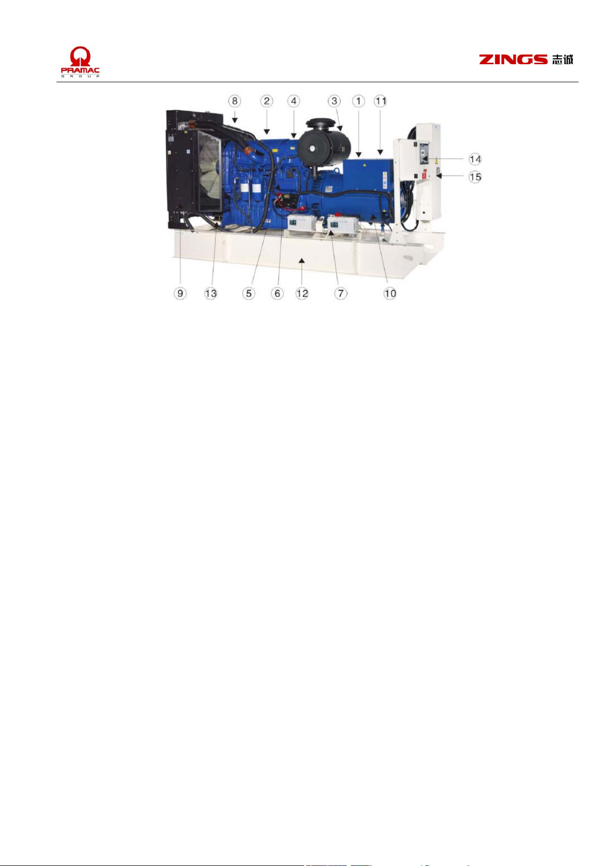
Picture 2:
Electric drill, churn drill and aiguilles several.
Aiguilles for electric drill specifications:
Ø5, Ø5.5, Ø6,
Aiguilles for churn drill specifications:
Ø10, Ø12, Ø14.
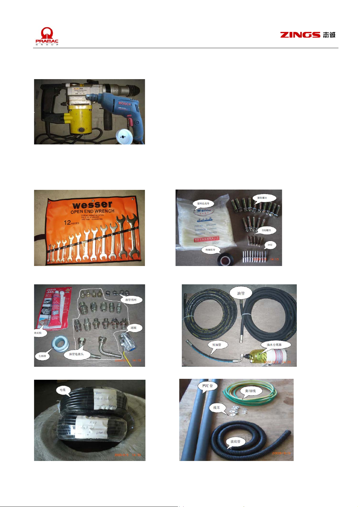
Picture 3:
Open end wrench Screws, rivet, insulation tape and binding.
Seal glue and fuel tank accessories Fuel pipes, tubes and fuel-water separator
Electrical cables PVC pipes, waveform tubes, ground cable etc.
13

3.3 Genset installation
a) Test centre line vertically and horizontally;
Find centre line of concrete base and genset and vibration damper line according to drawing before location.
Concrete base must be cleaned.
b) Lifting
Bind rope at genset gravity position and lay at datum line.
c) Genset lay flat and fixed
Level the genset by sizing block. Installation precision is 0.1mm each meter vertically and horizontally. Fix the genset
by expandable bolts, in case vibration damper is used between base frame and concrete base, no expandable bolts
are needed any more.
3.4 Auxiliary installation
3.4.1 Fuel refilling system installation
For different gensets, ZINGS can provide different configuration of fuel tank and fuel refilling system for options. The fuel tank
can be separated one or base frame type or customer designed, anyhow, the basic principle should as follows:
a) Fuel tank should be stored in safe and fire-proof place and keep a certain distance from genset, exhaust pipes, vibration
sources and any smoke is prohibited. For diesel fuel will be vaporized above 65℃ and can’t start engine any more.
Vibration may mix the contamination in fuel and block fuel way.
b) After fuel tank is located, the fuel level should not be 2.5M higher than base frame. If exceed 2.5M, additional day fuel tank
should be fitted. The lowest fuel level should not be lower than 1m of fuel pump mouth while fuel pump mouth to the bottom
of fuel tank not less than 100mm to avoid water or contamination injected into engine.
c) Fuel leakage must be avoided during fuel system installation. Fuel tube have to use ring band for winding instead of iron
wire, fuel pipes can use black iron pipe or steel wire pipe.
d) Fuel-water separator can bring big benefit. For water in fuel is dangerous to engine, which makes engine rusty and
damages injector mouth.
3.4.2 Exhaust system installation
T
he function of exhaust system is to emit smoke or others safely outdoor and keep away from building and human. Attention:
a) Exhaust pipe should connect flexible stainless steel waveform type. Waveform pipe can’t be used as elbow or appendix for
fuel pipe.
b) Silencer and exhaust pipe should be supported by bracket rather than exhaust pipe or it will be damages.
c) Heat insulation is suggested to silencer and exhaust pipe to avoid any accidental fire or extinguish equipment error.
d) Distance between tinder and exhaust pipe should be at least 290mm (9 inch). Anti flaming materials or heat insulation
gloves will be opted if exhaust pipe have to pass through ceiling and wall.
e) The end of exhaust system should be away from building and air inlet to avoid pollution.
f) It’s better to install exhaust system at the back of building.
g) End of exhaust pipe distance in some regulations:
3m from ground; 1m from ceiling or wall;
3m from building entrance;
at least 3m higher than other buildings.
h) Exhaust pipe outdoor should be 60°bent to ground if horizontal design or rainproof cover in addition if vertically design.
i) Two genset with one exhaust pipe is prohibited, neither with exhaust pipe of other equipments.
j) Exhaust pipe backpressure can’t exceed instruction limitation. High backpressure may cause high temp. Exhaust air and
dust which will hurt engine. As a result, it’s necessary to test genset backpressure at full load before get into use. To reduce
backpressure, exhaust pipe is better to be shorter, and straighter, if bending; the semi diameter should be 1.5 times of pipe
diameter.
※Warning:
!Exhaust air may hurt human body;
14

!All indoor genset should exhaust through non-leakage pipe, the installation must apply to relevant regulations, standards and
other requirements;
!Silencer, exhaust pipe and turbo charger may cause high temperature; human must keep away from them;
!Avoid exhaust smoke and air to be the public hazard.
3.4.3 Ventilation and cooling radiator
。
wer room ventilation is very important for equipment. Room temperature should keep below 30
Po
should be the same as air flow and airlet. Fresh air enters from genset end, through control panel, alternator, engine, radiator
and exit by cooling fan. The min airflow capacity is the summation of engine ignition air and cooling air capacity. The common
component of cooling system is radiator.
a) When the radiator is at the end of genset, location should be reasonable to make it near the exhaust hole, the max
distance from radiator to the exhaust hole is 150mm.
b) If above location is not feasible, another exhaust slot is needed, whose min across sectional area should be the same as
radiator cooling area, canvas wind slot with steel-made flanges is generally used to connect radiator and exhaust shutter.
c) Blocks are necessary near air inlet and outlet to reduce fan noise. Invalid area for shutter and gridding and engine cooling
and ignition air should be considered while calculating air inlet or air outlet area, ZINGS suggest to keep the air inlet area
twice of radiator area.
3.4.4 Battery start system
Normal volt
age for engine start system is 12V or 24V, standard configuration includes battery bracket and battery cables.
Battery can be acid-lead type or free maintenance type, the former need to add electrolyte before usage while the latter can be
used directly. Notice for installation:
a) Keep clean surface and around;
b) Open the filling hole and add electrolyte, keep the level 10-15mm higher than battery panel. New added electrolyte is easy
to be absorbed by battery panel, regular complement is necessary. Due to electrolyte is heating, it’s necessary to keep it
stand still after filling;
c) Connect battery panel correctly;
d) Charge battery shortly after discharging to avoid panel sulfating. While charging, make sure the polarity is correct.
e) Check other connection whether correct.
3.4.5 Electric system connection
Genset has co
a) Power cable, control panel and signal cable are PVC insulation copper cable. 1.5mm
nfigured control panel and complete cable devices, together with running, faulty etc. input and output terminals.
2
control cable is enough for use.
Power cable reference:
1. Single core cable
F. Genset axis direction
Genset
power
(KW)
Phase
cable
2
(mm
Neutral
cable
)
(mm2)
Ground
cable
(mm2)
40-50 16 6 4
65-85 35 16 4
100 50 16 6
120-140 95 25 6
175 120 35 10
15
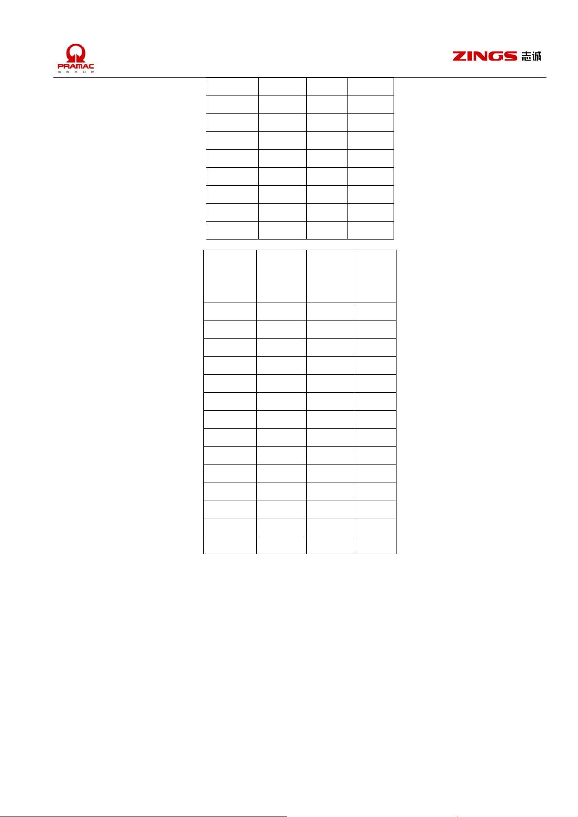
200-220 150 50 10
250-275 2×95 95 10
310 2×120 120 10
400 2×150 150 16
450 2×150 150 16
550 3×120 185 16
620-700 3×150 240 25
800-880 4×150 2×150 25
1120 4×240 2×240 25
2. 4 core cable
Genset
Phase
Neutral
Ground
power
(KW)
cable
(mm
cable
2
)
(mm2)
cable
(mm2)
40-50 25 16 4
65-85 70 35 4
100 95 50 6
120-140 120 70 6
175 2×70 2×35 10
200-220 2×95 2×50 10
250-275 3×70 3×35 10
310 3×95 3×50 10
400 3×120 3×70 16
450 4×95 4×50 16
550 4×120 4×70 16
620-700 4×185 4×95 25
800-880 4×240 4×120 25
1120 5×240 5×120 25
b) Direct burial cable requirements
Cable should be keep away from acid, and alkali area;
Depth should be not less than 500mm, with 100mm sand or soil at upper and lower layer;
Direction note at cross, turn, connection etc. should be marked by stake which should be 150mm higher than
ground.
16
 Loading...