

Page 1
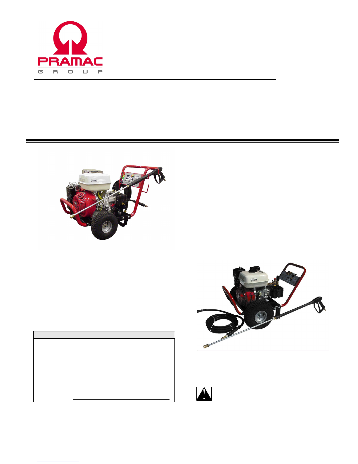
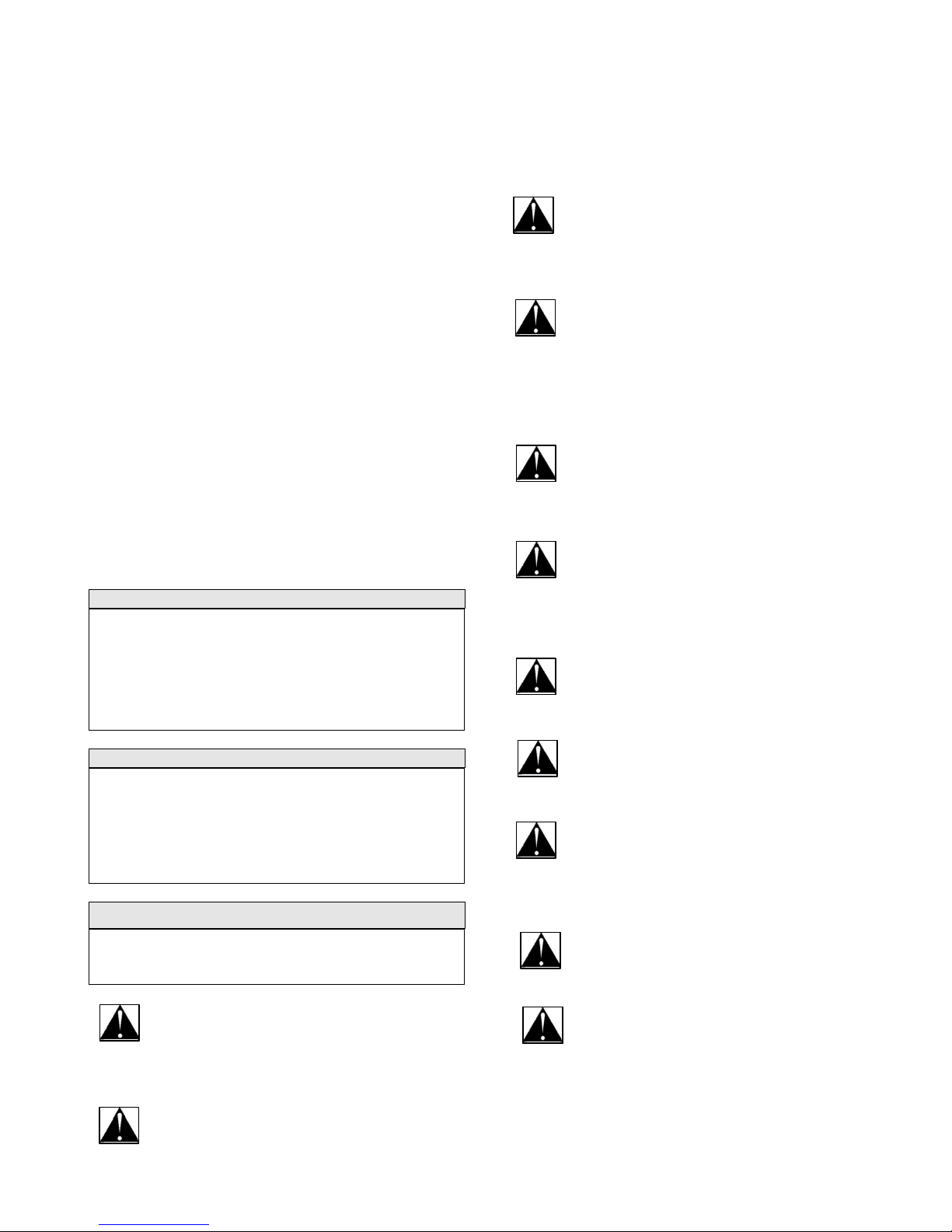
LD SERIES PRESSURE WASHERS
USERS MANUAL
Model Numbers
Power Systems
LD20
PW200
PW240
PW240 Model Shown
MODEL & SERIAL NUMBER
Enter the Model and Serial numbers of your pressure
washer in the spaces provided below. Retain these
numbers for future reference. The Model and Serial
numbers are located on the data plate on the base plate
or handle name plate, along with other important
information.
Model Number
Serial Number
DOCPRA0018 1
8/17/06 Rev. 1
LD20 Model Shown
Attention: Before operating your
Pressure Washer please read and
understand this manual. Please provide
this manual to any user or subsequent owner of
this machine.
Page 2

LIMITED 1 YEAR WARRANTY STATEMENT
A. PRAMAC Lifter pressure washers originally sold by PRAMAC Industries, Inc. or an authorized Distributor/ Dealer
thereof, are covered by a limited warranty for a period of 12 months. The Warranty period begins on the date of purchase by
the end user, 2 days after shipment to the end user by the PRAMAC Lifter™ Distributor/ Dealer, or 12 months from the date
of original invoice by PRAMAC Industries, Inc.- whichever occurs first. PRAMAC Industries, Inc. warrants their PRAMAC
Lifter products to be free of defects in materials and workmanship for the time period shown above and within the
limitations presented in the following. This PRAMAC Lifter Limited Warranty does not cover components or assemblies
manufactured by other organizations, including, but not limited to – engine, pump, lances, etc. Warranties for items and
assemblies not manufactured by PRAMAC Industries, Inc. are covered under the warranties of the respective
manufacturers of those products. Documentation concerning the warranty policies of items not manufactured by PRAMAC
Industries, Inc., but included as part of the PRAMAC Lifter pressure washer is included within the pressure washer
documentation.
These warranties are in lieu of and exclude all other warranties of merchantability, fitness, or otherwise, express or implied.
There are no warranties which extend beyond the description on the face thereof. The sole obligation of PRAMAC Industries,
Inc. (Seller) shall be to repair or replace any components thereof which are proved to be other than warranted. PRAMAC
Industries, Inc. shall have the sole right to determine whether such goods shall be repaired or replaced. This remedy of
repair or replacement is in lieu of all other remedies, and it is agreed that no other claim may be made by the Buyer. Buyer
and Seller agree that the sole purpose of this remedy is to provide the Buyer a satisfactory product under the contract. It is
further agreed that in no event shall the Seller be liable for incidental or consequential damages arising from any breach of
warranty. If goods are claimed to be other than as warranted the Seller or Sellers Authorized Agent, upon notice promptly
given, will issue shipping instructions for return to the Seller or Sellers authorized Agent (transportation costs to be
responsibility of Buyer) the goods or components, and if goods are proven to be other than as warranted, replacement or
repaired components will be shipped (cheapest way) to the Buyer with transportation costs paid by the Seller. PRAMAC
Industries, Inc. reserves absolute and final decision power regarding the warrantability of any and all failed components or
parts. Some states do not allow limitations on how long an implied warranty lasts, and some states do not allow the exclusion
or limitation of incidental or consequential damages, so the above limitations or exclusions may not apply to you. This
warranty gives you specific legal rights and you may also have other rights which vary from state to state.
B. All warranties of merchantability, fitness or otherwise, whether express or implied, shall not extend to any goods or parts
thereof which have been: subject to misuse or neglect, damaged by accident, rendered defective by reason of improper
handling or application, damaged or rendered defective due to tampering of factory set adjustments, damaged due to
shipment, damaged due to lack of maintenance, damaged due to collision, impact or shock loads, or damaged due to
corrosion. Further, any modifications to the intended and original designed use of the PRAMAC Lifter pressure washer will
negate all warranties. Seller does not accept any liability for normal wear and tear, typical maintenance, nor for charges for
repairs or replacements made without authority, nor contingent liability of any kind.
C. YOUR WARRANTY RESPONSIBILITIES: You are responsible for the performance of all maintenance including the use
of approved fluids. Upon first indication of a problem, you are to cease operation of your PRAMAC Lifterpressure washer
and report the problem to your Authorized PRAMAC Lifter Distributor/ Dealer. Upon request, you will be required to
produce proof of purchase and other pertinent information. Your Authorized PRAMAC Lifter Distributor/ Dealer will instruct
you regarding transportation (prepaid by buyer) of your PRAMAC Lifter product to the Authorized Distributor/ Dealer
location or arrange for shipment (prepaid by buyer) of the failed components to the Authorized Distributor/ Dealer for
warranty inspection. The name, address and telephone number of your local PRAMAC Lifter Distributor/ Dealer or
authorized service facility may be obtained by contacting PRAMAC Industries, Inc. at (770) 218-2810.
January 01, 2000
2
Page 3

GENERAL WARRANTY STATEMENT
Items on this pressure washer not manufactured by PRAMAC Industries, Inc. are not covered by the previously
defined 12 month warranty. Most of these parts carry a warranty from the respective manufacturer. The general
warranty information for these parts is described below. See the documentation provided by each manufacturer
which is included with this pressure washer for a complete definition of warranty and claims information. Please
note that in the event of discrepancies between this information and that of the manufacturer, the manufacturers
data takes precedence.
Engine
Honda GX160
Honda GX270
Honda GX390
2 year limited warranty
Pump
Annovi Reverberi (AR)
5 year limited warranty - North America
Accessories
Meccanica Veneta (Gun/Lance)
6 month limited warranty
3
Page 4

Contents
LIMITED 1 YEAR WARRANTY STATEMENT ......................................................................................................... 2
GENERAL WARRANTY STATEMENT...................................................................................................................... 3
SECTION 1..................................................................................................................................................................... 5
GENERAL INFORMATION........................................................................................................................................ 5
SAFETY RULES.......................................................................................................................................................... 5
GENERAL SAFETY OPERATIONAL GUIDELINES ................................................................................................. 6
GENERAL MAINTENANCE....................................................................................................................................... 6
CLEANING YOUR MACHINE.................................................................................................................................... 6
PRESSURE WASHER MAINTENANCE..................................................................................................................... 6
GENERAL STORAGE GUIDELINES.......................................................................................................................... 6
USING YOUR PRESSURE WASHER ......................................................................................................................... 7
PRESSURE WASHER SPECIFICATIONS .................................................................................................................. 8
GENERAL PRODUCT INFORMATION ..................................................................................................................... 8
TROUBLESHOOTING PROCEDURE......................................................................................................................... 9
SECTION 2....................................................................................................................................................................10
LD20 PARTS AND PART LISTS................................................................................................................................10
SECTION 3....................................................................................................................................................................12
LD30 PARTS AND PART LISTS................................................................................................................................12
SECTION 4....................................................................................................................................................................14
LD35 PARTS AND PART LISTS................................................................................................................................14
All information provided in this manual is believed to be correct at the time of printing. The manufacturer reserves the right to correct any
errors and omissions.
4
Page 5
SECTION 1
GENERAL INFORMATION
This manual is provided for you so that your
pressure washer may be properly, safely and
effectively applied and operated. Please read and
understand all aspects of this manual before
operating your pressure washer. Please also read
and understand the documentation supplied with
this pressure washer regarding the engine and
pump. Keep this documentation in a safe and
accessible place so that reference can be made as
needed. All operators, users and subsequent
owners of this pressure washer must read and
understand all aspects of this documentation before
operation. Please make note that your pressure
washer is equipped with a thermal relief valve. If
water begins to spray from your pump during
operation it is likely because water temperature
has exceeded 140°F. This usually occurs if the
machine is left running during periods(usually 5
minutes or more) of non-use. This is a safeguard
against damage which can occur with high water
temperatures. It is recommended that the engine be
shut down if the pressure washer will not be used
for extended periods.
SPARK ARRESTING MUFFLER
Certain States and Jurisdictions require that engine
driven equipment be fitted with spark arresting mufflers.
Depending on the model, spark arresting mufflers may
or may not be fitted. If spark arresting mufflers are
required for your specific location and the pressure
washer muffler is not spark arresting, contact your local
dealer for instructions for a retrofit.
EXHAUST EMISSION CONTROL SYSTEM
The exhaust emission control system for this pressure
washer complies to the standards set forth by the
California Air Resources Board (CARB) and the
Environmental Protection Agency (EPA). Warranties for
the exhaust emission system are administered by the
respective engine manufacturers. Refer to the engine
documentation for warranty information.
WARNING
The engine exhaust from this product contains
chemicals known to the State of California to cause
cancer, birth defects, or other reproductive harm.
THIS SYMBOL IS USED THROUGHOUT YOUR
OWNER’S MANUAL TO BRING ATTENTION TO
IMPORTANT SAFETY INSTRUCTIONS. FAILURE TO
READ, UNDERSTAND AND FOLLOW SAFETY
INSTRUCTIONS COULD ENDANGER YOU OR OTHERS AND
RESULT IN PERSONAL INJURY OR DEATH.
DO NOT OPERATE THIS PRESSURE WASHER
WITHIN AN ENCLOSED AREA. THE EXHAUST
GASES OF THIS PRESSURE WASHER EMIT “DEADLY”
CARBON MONOXIDE. EXPOSURE TO CARBON MONOXIDE
CAN CAUSE CARBON MONOXIDE POISONING,
HEADACHES, NAUSEA, SEVERE SICKNESS OR DEATH.
DANGER: PARTS OF THIS PRESSURE WASHER
SUCH AS THE ENGINE, MUFFLER, AND PUMP CAN
BECOME VERY HOT DURING OPERATION.
CONTACT WITH THESE PARTS CAN CAUSE SERIOUS
INJURY. ALWAYS ALLOW ADEQUATE COOL DOWN TIME
BEFORE SERVICING.
DANGER: NEVER ADD FUEL TO A HOT MACHINE
OR RUNNING MACHINE. HOT ENGINE PARTS
SPARKS, OR LIT CIGARETTES COULD IGNITE
GASOLINE. NEVER STORE FUEL OR OTHER
COMBUSTIBLE MATERIAL NEAR THIS MACHINE.
SAFETY RULES
DANGER: This equipment produces a very high
pressure stream of water which can penetrate
the skin and cause serious injury. Under no
circumstance should the spray gun be aimed at people,
animals or any delicate items which might be damaged.
DANGER: Users of this machine should always
dress properly before using. Safety glasses,
shoes, long pants, shirt, and ear protection are
recommended. Specific situations, such as during
chemical application, could require a much greater level
of protective clothing.
DANGER: When using chemicals in conjunction
with this machine you should always wear gloves,
eye protection and clothing which leaves no
exposed skin.
DANGER: Never point the output water stream
at electrical wiring or devices. This can lead to
damaged components, personal injury or even
fatal electrical shock.
CAUTION: Do not modify the factory engine
settings on your pressure washer. The factory
settings are made to produce the designed
pressure and flow rate for your equipment. Any
misapplication can lead to damaged components or even
bodily injury.
CAUTION: Only qualified personnel should be
allowed to use this machine. Under no
circumstances should children be allowed to
operate this machine.
CAUTION: The water supply should always be
clean. Never use water if it contains dirt, sand,
chemicals or any other foreign matter. For information
regarding chemical use refer to the section titled Chemical
Application included later in this manual.
5
Page 6

GENERAL SAFETY OPERATIONAL
GUIDELINES
Read and understand all of the general safety
operational guidelines and rules before operating
this pressure washer.
Always follow National and Local codes and
restrictions.
When moving or transporting this machine, take
proper precautions to avoid fuel spillage. Further,
always use common sense when lifting this pressure
washer. An adequate number of people and proper
lifting procedures must be used.
Whenever changing or adjusting the spraying tip you
should always use the trigger lock-off feature on the
spray gun. This feature should also be engaged
when making any other adjustments to this machine;
the machine should never be left unattended.
Do not operate this pressure washer unless the lock-
off feature on the gun is in good mechanical
condition.
Do not operate this machine above the maximum
factory preset pressure.
Always inspect this machine for damaged, loose or
missing parts before use.
The area of operation should be relatively
obstruction free and very well ventilated.
Always locate this machine on a relatively flat (20%
grade or less) and stable surface before operation.
Use proper parts, which are equivalent to those
provided when new, if performing maintenance or
repairs. Improper parts could cause damage or
reduced performance of your machine.
Always remember that the muffler, engine, and
pump can become very hot during operation and
remain that way for a considerable time.
Gasoline is highly FLAMMABLE and its vapors
are EXPLOSIVE. Handle gasoline with extreme
care. Failure to properly handle gasoline can result
in explosion or fire. Do not permit smoking within
50ft of this machine.
NEVER REFILL A HOT OR RUNNING PRESSURE
WASHER WITH FUEL. Spillage onto the engine or
other hot parts could result in an explosion or fire.
Always allow the unit to cool before refilling.
Do not store this machine in any location where
gasoline fumes could potentially come into contact
with sparks, a pilot light or an open flame. Improper
storage could result in an explosion or fire.
Inspect the high pressure hose often. In the event a
hose becomes damaged, discontinue use
immediately and replace with a properly rated hose.
Service or fluid level inspection should be performed
on a level surface only.
GENERAL MAINTENANCE
ENGINE FUEL: Use Unleaded Fuel - ONLY!
ENGINE OIL AND MAINTENANCE: Refer to the
Engine related documentation for specifications and
recommended maintenance schedule.
HOSES: Inspect the high pressure hose, garden hose
and chemical hose often. Defects can cause
decreased performance or damage to the machine.
WATER AND CHEMICAL FILTERS: Inspect any filters
supplied with your unit for damage or debris before
each use.
SPRAY GUN AND NOZZLES: Inspect the gun, lance,
and nozzles for leakage each use. Also, ensure the
lock-off mechanism on the gun is operational before
each use.
CHEMICAL HOSE: The hose should be flushed after
each application of chemicals. Do this by inserting
the hose into a bucket of clean water and running the
unit in low pressure (chemical application) mode for a
few minutes.
CLEANING YOUR MACHINE
CAUTION!: ALWAYS SHUT OFF THE PRESSURE
WASHER AND ALLOW TO COMPLETELY COOL
BEFORE PERFORMING CLEANING OPERATIONS.
Compressed air (max. 25 psi) may be used to blow
loose dirt and dust from your machine. DO NOT
DIRECT COMPRESSED AIR DIRECTLY INTO ANY
OPENING IN THE ENGINE OR AT PEOPLE OR
ANIMALS.
Use a dampened cloth to wipe clean exterior
surfaces.
Use a soft bristle brush to clean/ loosen heavy dirt, oil
or grease deposits.
NEVER insert rags, tools or any device into the
engine openings.
PRESSURE WASHER MAINTENANCE
During the course of standard use you will find that some
items wear out. The most common of these will probably
be the spray tips and the o-rings at some of the joints.
This is natural and when you consider the high pressure
applied it should be expected. These are very simple to
replace and when replacement parts are needed simply
contact the Dealer/Distributor where the pressure washer
was purchased.
The spray tips may also become clogged from time to
time. You will notice the pump pulsing and also pressure
buildup. This can be easily corrected by removing the tip
from the wand following proper safety procedures and
using a small wire, push the wire through the tip in the
reverse direction of water flow.
GENERAL STORAGE GUIDELINES
WARNING: GASOLINE FUMES ARE FLAMMABLE.
DO NOT STORE YOUR PRESSURE WASHER IN
ANY AREA THAT IS INDOORS OR IN POORLY
6
Page 7

VENTILATED AREAS. GASOLINE FUMES CAN IGNITE IN
THE PRESENCE OF ANY OPEN FLAME, PILOT LIGHT,
CLOTHES DRYER, WATER HEATER, ETC.
Your machine should be started and operated for
several minutes at least every 30 days.
If the machine cannot be operated every 30 days,
follow the storage recommendations within the engine
documentation. Disconnect all hoses and drain
completely. Also, be certain that the pump is drained
completely. Turn over the engine with the recoil
starter several times to do this.
NOTE: A fuel shut-off valve is positioned on the
engine. The valve should be closed during storage
periods.
USING YOUR PRESSURE WASHER
Refer to the General Product Information Section for
visual reference to this section.
Assembly
The first step after removing your generator from the box
is assembling the handle and the hoses. The handle is
mounted to the base plate along with the rear support
piece using the carriage bolts supplied. Please note that
the battery kit for electric start models should be intalled at
the same time as the handle. The gun and hose can now
be attached using the quick connect fittings. Refer to the
pictures in the parts list section of this manual for
clarification.
Preparation for Starting the Pressure Washer
After assembly you are almost ready. Next, remove the
shipping cap from the oil inlet on the pump and replace it
with the supplied dipstick. Now add oil to the engine as
specified in the engine documentation. Finally, put
gasoline into the fuel tank on the engine.
Starting the Pressure Washer
Verify that the lubrication levels are correct. Connect the
pump to a water supply capable of providing at least
4.5gpm and turn the water on. Most outdoor faucets
provide an adequate supply of water. If you are not sure
you have a proper water supply then simply measure the
amount of time it takes to fill a container of a known
quantity, such as a one gallon milk jug, and determine the
flow rate. You should never run the machine without being
connected to an adequate water supply. Squeeze the gun
trigger until a steady flow of water comes from the tip.
Turn the fuel valve to the ON position and choke the
engine as needed. Be sure to set the lock-off device on
the gun. Turn the engine ON/OFF switch to the ON
position and now give a firm pull on the recoil starter (or
turn the key for electric start models). Return the choke to
the standard position as the engine warms up.
Stopping the Pressure Washer
Discontinue use of the spray gun. Turn the engine switch
to the off position. When the engine is at rest, squeeze the
trigger to release the pressure in the pump. Turn the fuel
valve to the off position. Turn the water supply off.
Squeeze the trigger to release any remaining water from
the pump. Note: This does not replace the procedures for
storing the pressure washer because it will not completely
empty the pump and hoses.
Using your Pressure Washer
Your pressure washer is designed to clean surfaces
through the use of high water pressure. The extreme
pressure produced can damage surfaces if care is not
used. Always test in an obscure area to determine the
proper spray angle and distance between tip and surface
starting about 2 feet away and gradually moving closer.
The spray angle is determined by the color coded tips or
by turning the knob on the adjustable style tip.
Interchanging tips or adjusting spray angle on
adjustable tips should only been done with the gun
lock-off feature engaged. The following is a description
of the tips. Note that all tips are not included with your
pressure washer.
Adjustable Tip. This tip is typically barrel shaped and
rotates around the lance axis to adjust spray angle. To
apply chemicals with this tip, grasp the tip firmly and pull
away from the gun making certain the trigger is locked off.
This should “click” into the low pressure mode. After
applying chemicals simply pull the tip back to the original
position for high pressure spraying. Experiment with the
angle adjustments for the optimum cleaning position for
each surface.
The following 5 tips are typically included as a set when
the adjustable tip is not used. These utilize a quickcoupler to switch between tips.
Low Pressure – Black. This tip is used to apply
chemicals at low pressure. This nozzle has a 25° spray
angle.
0° - Red. Provides the most cleaning force but over a
smaller area.
15° - Yellow. Provides strong cleaning force over a
slightly larger area.
25° - Green. Provides good cleaning force over a larger
area. Popular for surfaces which do not have too much
tough dirt because of the wider area and good force.
40° - White. Provides the most gentle force but over the
largest area.
Chemical Application. Always dress properly when using
chemicals. Chemical application can only be done in the
low pressure mode through the supplied chemical
injection system. The chemical tube should be inserted
into the chemical tank and the Black tip installed or the
adjustable tip set in low pressure position. The chemicals
are automatically drawn into the water flow and applied to
the surface to be cleaned. After application, return to the
desired high pressure settings to clean. Chemicals should
never be introduced through the water supply because
they will damage the internals of the pump. They should
only be supplied through the downstream chemical
injector included with the machine. Care should always be
taken when using chemicals because they can be harmful
to people, animals, and plants. Care should also be taken
to prevent overspray on the pressure washer itself
because they can corrode the external components.
7
Page 8

PRESSURE WASHER SPECIFICATIONS
Table 1 outlines the specifications for each model.
Table 1 SPECIFICATIONS
Model Pressure(psi) Flow(gpm) Engine
LD20HHP 2000 3 Honda GX160 (5.5HP)
PW200 3000 3 Honda GX270 (9HP)
PW240 3500 4 Honda GX390 (13HP)
GENERAL PRODUCT INFORMATION
LD35 Shown, other models may vary slightly in appearance.
8
Page 9

TROUBLESHOOTING PROCEDURE
Problem Possible Cause Solution
Low Pressure 1. Blockage or kink in supply line.
2. Leak in system.
3. Clogged spray nozzle.
4. Faulty pump or unloader valve.
5. Water temperature too high.
Engine Will Not Start 1. No oil.
2. No gas.
3. Bad gas.
4. Spark plug problem.
5. Air cleaner problem.
6. Other.
Engine Loads Up
When Not Actively
Spraying
Chemicals Do Not
Mix In Outlet Spray
Pump Oil Emulsified
(Grey in Color)
Engine Shuts Down 1. Out of fuel.
1. Unloader valve setting too high.
2. Faulty unloader valve.
1. Nozzle in high pressure mode.
2. Clog or kink in chemical hose.
3. Chemical hose not fully
immersed.
1. Worn oil seals. 1. Contact pump service point.
2. Oil level is low.
1. Check water supply, supply line, and filter for
kinks or blockage.
2. Check all connections for leaks and replace
any worn parts causing problems.
3. Clean nozzle.
4. Contact pump service point.
5. Use different water source.
1. Add oil as specified by engine manufacturer.
2. Add fuel.
3. Drain fuel tank and use fresh fuel.
4. Connect spark plug wire or replace spark
plug.
5. Clean or replace.
6. Contact engine service point.
1. Adjust unloader valve to lower pressure.
2. Contact pump service point.
1. Use black low pressure tip or set adjustable
tip to low pressure mode.
2. Unclog and/or straighten hose.
3. Make sure chemical hose is fully immersed in
the chemical solution.
1. Add fuel.
2. Add oil.
9
Page 10

SECTION 2
LD20 PARTS AND PART LISTS
10
Page 11

11
Page 12

SECTION 3
PW200 PARTS AND PART LISTS
ITEM
NO. QTY. PART NO. DESCRIPTION
1 2 WHE0001 Wheel, 10" Pneumatic
2 1 FRA0064_Bumper Frame, Bumper
3 1 BRA0061_FrameSupport Frame Support
4 2 VIB0015_50X16 Isolator, 50 X 16 X 10mm
5 6 M10 lockwasher Lockwasher, M10
6 6 m10 nut Nut, M10
11 10 M8-1.25 x 30
16 1 XMV4G30D 3gpm, 3000psi, 3400rpm Pump
17 1 GUN0003 High Pressure Spray Gun
GUN0002
18 1
19 8 SCRM080005_CarriageBolt Carriage Bolt, M8 X 60
20 8 M8 NUT Nut, M8 - Nylon Insert
21 7 M8 flatwasher Flatwasher, M8
22 1 VAL0004_ThermalValve Thermal Relief Valve
23 4 M10 x 40 Bolt Bolt, M10 x 40 Z
24 2 1-8 cotter pin 1/8" Cotter Pin
25 2 WASHER- FLAT- 5-8 Washer, 5/8" Flat
26 1 HOS0009_ChemHose 3' Chemical Injection Hose
27 1 CPL0001 Quick Couple (Fem x Fem)
28 1 CPL0002 Quick Couple (Male x Male)
29 1 CPL0003 Quick Couple (Garden x Male)
30 1 TIP0006_0Deg_3000psi 0 Degree Nozzle, #3.5
31 1 TIP0007_15Deg_3000psi 15 Degree Nozzle, #3.5
32 1 TIP0008_25Deg_3000psi 25 Degree Nozzle, #3.5
33 1 TIP0009_40Deg_3000psi 40 Degree Nozzle, #3.5
34 1 TIP0005_25Deg_Chemical 25 Degree, Chemical Nozzle
(Connected to Gun0003)
Lance, Gun Extension
12
Page 13

35 1 PLA0025-2_BasePlate Base Plate
36 1 AXL0013_Axle Axle
37 2 BRA0064_1_AXLE MONTE
38 1 FRA0065_Handle Frame, Handle
39 1 BRA0063_HOSEHOLDER
42 1 BRA0022-0_WandHolder Bracket, Wand
43 5 GRM0004 .438 ID X .563OD Grommet
44 2 SCRM100001_M10x40_Z Bolt, M10 x 40 Z
45 5 WASM100001_Lock Lockwasher, M10
46 4 NUTM100001_Nut Nut, M10
47 1 BRA0065_Front GunHolder Bracket, Wand
48 1 HOS0007_50FT Hose, 50 FT x 3/8" ID
PW200 EXPLODED VIEW
13
Page 14

SECTION 4
PW240 PARTS AND PART LISTS
ITEM
NO. QTY. PART NO. DESCRIPTION
1 2 WHE0001 Wheel, 10" Pneumatic
2 1 FRA0064_Bumper Frame, Bumper
3 1 BRA0061_FrameSupport Frame Support
4 2 VIB0015_50X16 Isolator, 50 X 16 X 10mm
5 6 M10 lockwasher Lockwasher, M10
6 6 m10 nut Nut, M10
11 10 M8-1.25 x 30
16 1 RKV_4G35 4gpm, 3500psi, 3400rpm Pump
17 1 GUN0001 High Pressure Spray Gun
GUN0002
18 1
19 8 SCRM080005_CarriageBolt Carriage Bolt, M8 X 60
20 8 M8 NUT Nut, M8 - Nylon Insert
21 7 M8 flatwasher Flatwasher, M8
22 1 VAL0004_ThermalValve Thermal Relief Valve
23 4 M10 x 40 Bolt Bolt, M10 x 40 Z
24 2 1-8 cotter pin 1/8" Cotter Pin
25 2 WASHER- FLAT- 5-8 Washer, 5/8" Flat
26 1 HOS0009_ChemHose 3' Chemical Injection Hose
27 1 CPL0001 Quick Couple (Fem x Fem)
28 1 CPL0002 Quick Couple (Male x Male)
29 1 CPL0003 Quick Couple (Garden x Male)
30 1 TIP0001_0Deg_3500psi 0 Degree Nozzle, #4.0
31 1 TIP0002_15Deg_3500psi 15 Degree Nozzle, #4.0
32 1 TIP0003_25Deg_3500psi 25 Degree Nozzle, #4.0
33 1 TIP0004_40Deg_3500psi 40 Degree Nozzle, #4.0
34 1 TIP0005_25Deg_Chemical 25 Degree, Chemical Nozzle
(Connected to Gun0001)
Lance, Gun Extension
14
Page 15

35 1 PLA0025-2_BasePlate Base Plate
36 1 AXL0013_Axle Axle
37 2 BRA0064_1_AXLE MONTE
38 1 FRA0065_Handle Frame, Handle
39 1 BRA0063_HOSEHOLDER
42 1 BRA0022-0_WandHolder Bracket, Wand
43 5 GRM0004 .438 ID X .563OD Grommet
44 2 SCRM100001_M10x40_Z Bolt, M10 x 40 Z
45 5 WASM100001_Lock Lockwasher, M10
46 4 NUTM100001_Nut Nut, M10
47 1 BRA0065_Front GunHolder Bracket, Wand
48 1 HOS0007_50FT Hose, 50 FT x 3/8" ID
PW200 EXPLODED VIEW
15
Page 16

Section 5
Assembly
16
Page 17

Notes
17
Page 18

18
 Loading...