

Pramac ES5500X 5.5 KW Supplemental Instructions

Supplemental Instructions
for
Pramac ES5500X 5.5 KW
Generator Set
1 December 2003
NSWC Coastal Systems Station
Panama City, FL

This package includes the following supplemental items and instructions to be used
with the previously shipped Pramac ES5500X 5.5 KW Generator Set, supplied as part
of the USS Cole damage control lessons learned package:
a. Pramac Industries Technical Service Bulletin 1001 (Power Panel Rewiring
and Ground Removal)
b. Wiring Check Template (used during power panel rewiring)
c. Repair Parts Kit for Generator (submit to Supply Officer)
d. Installation instructions for adding replacement fuel prime line (air vent)
e. Generator Mobility Kit (Ancillary equipment)
f. Allowance Parts List (APL) 16A030002
g. Maintenance Index Page (MIP)/Maintenance Requirement Cards (MRCs)
The Pramac Industries service bulletin (TSB 1001) for the ES5500X generator
series, dated 23 June 03, accomplishes two tasks: (1) corrects an incorrect wiring
problem of the power panel to allow a full 40 amp service to the duplex receptacles, and
(2) removes an incorrectly-wired ground, allowing the 10” damage control circular saw
to function with this generator.
As an aid to rewiring the panel, two figures, included immediately following TSB
1001, may be used as a guide. The first figure is a template that may be inserted
directly above the terminal board before and after the rewiring steps to determine if the
wiring to the terminal board is correct. The second figure illustrates use of the template
during rewiring.
When following TSB 1001, also note these discrepancies:
• Pramac does not need to be contacted for the replacement part (as indicated
on the TSB); it is provided as part of this delivery.
• It is very easy to overlook the remark in the TSB that there are two procedures included in the instruction. Be sure to read through both sets of
instructions first. Note that when step #13 of procedure 1 is complete, DO
NOT PUT THE UNIT BACK TOGETHER, but proceed to step #2 of the
second procedure. After step #5 of the second procedure, go back to step
#14 of the first procedure, and finish.
During evaluation of the TSB, it was determined that it should require no more
than 45 minutes to perform.
A repair parts kit is also provided. This kit should be submitted to the supply
officer. Parts in this kit match the APL for the generator set.
In addition to the above TSB, the Coastal System Station has developed two
modifications to improve operation and mobility of the generator, including a fuel system
air purge, which allows the fuel system to be purged of air without removing fuel lines.
The second modification is a generator mobility kit, which consists of wheels and
handles. Information on both modifications is also found in this package.
Any questions concerning the above may be addressed to Mr. K. Powell, NSWC
CSS Panama City, Code E50L, Commercial (850) 234-4198, DSN 436-4198, or E-Mail
at powellke@ncsc.navy.mil.
1

Pramac Industries
SERVICE BULLETIN TSB1001
Date: 23-Jun-03
PRODUCTS INVOLVED
ES5500X(ES5500MYHDI-AB00W) generators with serial numbers between 2002US21034 and
2003US25890.
ISSUE
Some generators may have been produced with the wiring between the alternator and the electrical
panel connected improperly. There may also be a ground to neutral jumper wire in the control panel.
This bulletin has been produced to define parts and procedures in correcting the wiring.
SYMPTOMS
On generators with this problem, one of the circuit breakers will trip upon cranking. This can go unnoticed because the generator may continue to perform, however, maximum capacity cannot be
obtained. The circuit breakers also have weather boots, which can disguise the fact that the circuit
breaker has tripped. There may also be problems with the GFCI tripping when using certain tools,
specifically a Milwaukee brand 6460 circular saw. Note: This does not present a safety problem.
ACTIONS
For generators within the defined serial number range and model number experiencing the
previously described problems a new wiring harness, part number PIT0005, will be provided under
warranty. Contact the Service/Warranty Manager at (770) 479-2922 and reference this TSB number.
Note that the existing wiring diagram in the generator manual is correct and may be used when
connecting the new wire harness. An electrical diagram is also shown on page 2. Where the ground
to neutral jumper exists on the panel, use the following procedures to remove it.
There are 2 sets of procedures below. If your generator exhibits both problems the corrective actions
can easily be combined. Read both sets of procedures thoroughly.
Upon receipt of the wiring harness from the Service/Warranty Department follow the steps below to
correct the generator wiring.
Tools required: Phillips head screwdriver, small standard screwdriver, 10mm Socket or wrench.
Make certain that the generator is not running before beginning. Read the instructions completely
before beginning work. Refer to page 2 for photos showing the harness correctly installed.
1. Remove the back cover from the alternator using a Phillips head screwdriver and removing
the 4 screws in the corners.
2. Disconnect the green wire from the alternator body inside the panel with the same
screwdriver.
3. Disconnect the existing harness from the alternator by pulling the white connector apart.
4. Remove the bolts around the perimeter of the control panel using the 10mm socket or wrench
and rotate the panel down.
5. Using the standard screwdriver, disconnect the existing harness(5 wires – 1 green, 2 white, 2
black) from the bottom of the terminal block which is mounted on the control panel.
6. Remove the existing harness from the generator and discard. Route the new harness into
roughly the same position as the old one.
Page 1 of 3

Pramac Industries
SERVICE BULLETIN TSB1001
7. Connect the white connector of the new harness to the white connector in the alternator
noting that the wire colors of the new harness correspond to those on the alternator.
8. Connect the green wire with the ring terminal on the end to the same ground position in the
alternator as the previous harness using the same screw.
9. In the control panel, connect the Green wire from the harness to the position on the
connector block opposite the green wire.
10. Connect the Brown wire of the harness to the position on the connector block opposite the
white wire which connects directly to one of the receptacles.
11. Connect the Blue wire of the harness to the position on the connector block opposite the
black wire which connects directly to one of the receptacles.
12. Connect the White wire of the harness to the position on the connector block opposite the
white wire which connects directly to one of the circuit breakers.
13. Connect the Black wire of the harness to the position on the connector block opposite the
black wire which connects directly to one of the circuit breakers.
14. Reinstall the control panel and the alternator end cap.
15. Make certain that all circuit breakers are re-set by pushing the black buttons on the front of
the control panel. Note that these buttons may be hidden by weather boots.
Figure 1. Alternator Figure 2. Control Panel
Elec. Diagram – Control Panel
Page 2 of 3
Pramac Industries
SERVICE BULLETIN TSB1001
Follow the steps below to remove the ground to neutral jumper wire.
Tools required: Phillips head screwdriver, 10mm Socket or wrench.
Make certain that the generator is not running before beginning. Read the instructions completely
before beginning work.
1. Remove the bolts around the perimeter of the control panel using the 10mm socket or wrench
and rotate the panel down.
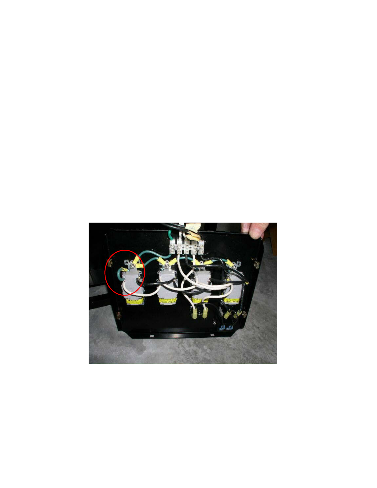
2. Locate the ground to neutral jumper. It should be a green wire connected from a
ground(green wires) point to a neutral(white wires) point. Reference Figure 3 below for the
typical position, circled in red. Note that the jumper could possibly be on any of the
receptacles but should be as shown below.
3. Loosen the green screw on the receptacle where one end of the jumper is connected and
remove the jumper from that position. Re-tighten the screw.
4. Loosen the silver screw on the receptacle at the other end of the jumper wire. Remove the
jumper from that position. Re-tighten the screw making sure that the white wire remains
connected. Discard the jumper wire.
5. Reinstall the control panel.
6. Make certain that all GFCI receptacles are reset by pushing the reset buttons on the front of
the receptacles.
Figure 3. Control Panel
Page 3 of 3
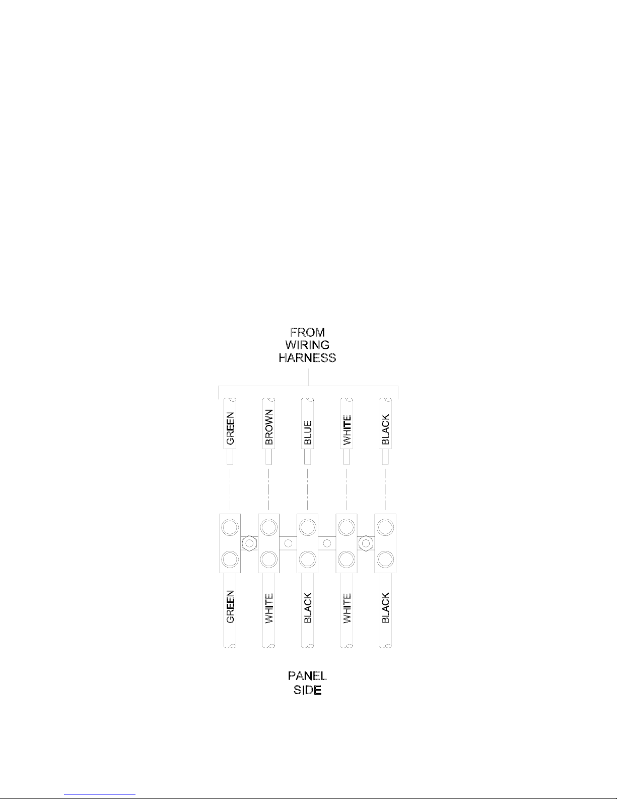
WIRING HARNESS TEMPLATE
5
 Loading...