


1295
Industrial
®
1296
INSTRUCTION MANUAL
This instruction manual applies to machines from the
following serial numbers onwards:
# 2 730 099
296-12-18 639/002
Betriebsanleitung engl. 06.09

This Instruction Manual is valid for all models and subclasses listed in the
chapter "Specifications ".
The adjustment manual for the machines can be downloaded free of charge
from the internet address
www.pfaff-industrial.com/pfaf
As an alternative to the internet do
f/de/service/downloads
wnload the adjustment manual can also be
ordered in book form under part no. 296-12-18 640/002.
The reprinting, copying or translation of PFAFF Instruction Manuals, whether in whole or
in part, is only permitted with our previous authorization and with written reference to the
source.
PFAFF Industriesysteme
und Maschinen AG
Hans-Geiger-Str. 12 - IG Nord
D-67661 Kaiserslautern

Contents
Contents ............................................................................... Chapter - Page
1
1.01 Regulations ................................................................................................................ 1 -1
1.02 General notes on safety ............................................................................................. 1 - 1
1.03 Safety symbols .......................................................................................................... 1 - 2
1.04 Important notes for the user ...................................................................................... 1 - 2
1.05 Notes for operating and technical staff ...................................................................... 1 - 3
1.05.01 Operating staff ...........................................................................................................1- 3
1.05.02 Technical staff ............................................................................................................ 1 - 3
1.06 Danger warnings ........................................................................................................ 1 - 4
2 Proper use................................................................................................................. 2 - 1
3 Specifications ........................................................................................................... 3 - 1
3.01 PFAFF 1295, PFAFF 1296 .......................................................................................... 3 - 1
3.02 Possible versions and subclasses .............................................................................. 3 - 2
3.03 Maximum speeds of the PFAFF 1295 ........................................................................ 3 - 2
3.04 Maximum speeds of the PFAFF 1296 ........................................................................ 3 - 2
4 Disposal of the machine .......................................................................................... 4 - 1
5 Transportation, packing and storage ...................................................................... 5 - 1
5.01 Transportation to the customer’s premises ............................................................... 5 - 1
5.02 Tansportation inside the customer’s premises .......................................................... 5 - 1
5.03 Disposal of packing materials..................................................................................... 5 - 1
5.04 Storage ......................................................................................................................5- 1
Safety ........................................................................................................................ 1 -1
6 Explanation of symbols ........................................................................................... 6 - 1
7 Controls .................................................................................................................... 7 - 1
7.01 On/off switch ............................................................................................................. 7 - 1
7.02 Pedal (on machines without subclass -917/97) .......................................................... 7 - 1
7.03 Pedal (on machines with subclass -917/97)................................................................ 7 - 2
7.04 Knee lever (on machines without subclass -911/97 ................................................... 7 - 2
7.05 Key on machine head (on machines with subclass -911/97) ...................................... 7 - 3
7.06 Presser bar lifter......................................................................................................... 7 -3
7.07 Feed regulator/reverse sewing................................................................................... 7 - 4
7.08 Feed regulator (on machines with subclass -911/97) ................................................. 7 - 4
7.09 Adjusting nut for the top feed stroke ......................................................................... 7 - 5
7.10 Control panel .............................................................................................................. 7 -5
8 Installation and commissioning .............................................................................. 8 - 1
8.01 Installation .................................................................................................................. 8 - 1
8.01.01 Adjusting the table-top height .................................................................................... 8 - 1
8.01.02 Assembling the motor (only on machines with Quick-motor)..................................... 8 - 2
8.01.03 Tightening the V-belt .................................................................................................. 8 - 2
8.01.04 Mounting the bottom V-belt guard ............................................................................. 8 - 3

Contents
8
.01.05 Fitting the upper belt guard ........................................................................................ 8 - 4
8.01.06 Fitting the synchronizer .............................................................................................. 8 - 4
8.01.08 Fitting the reel stand .................................................................................................. 8 -5
8.01.07 Fitting the tilt lock....................................................................................................... 8 - 5
8.02 Connecting the plug-in connections and earth cables ................................................ 8 - 6
8.03 Commissioning .......................................................................................................... 8 - 7
8.04 Switching the machine on/off .................................................................................... 8 - 7
8.05 Basic position of the machine drive unit..................................................................... 8 - 7
9 Setting up ................................................................................................................. 9 - 1
9.01 Inserting the needle on the PFAFF 1295 .................................................................... 9 - 1
9.02 Inserting the needle on the PFAFF 1296 .................................................................... 9 - 2
9.03 Winding the bobbin thread, regulating the winder tension ......................................... 9 - 3
9.04 Changing the bobbin .................................................................................................. 9 - 4
9.05 Threading the bobbin thread and regulating the bobbin thread tension ......................... 9 - 4
9.06 Threading needle thread/adjusting needle thread tension on the PFAFF 1295 ..................... 9 - 5
9.07 Threading needle thread/adjusting needle thread tension on the PFAFF 1296 ..................... 9 - 6
9.08 Adjusting the stitch counter for the bobbin thread control ........................................ 9 - 7
Contents ...............................................................................Chapter - Page
10 Care and maintenance ........................................................................................... 10 - 1
10.01 Cleaning ................................................................................................................... 10- 1
10.02 General oiling ........................................................................................................... 10 - 2
10.03 Oiling the sewing hook ............................................................................................ 10 - 3
10.04 Oiling the needle-head parts .................................................................................... 10 - 4
10.05 Lubricating the top-feed drive eccentric ................................................................... 10 - 4
10.06 Checking/regulating the air pressure ........................................................................ 10 - 5
10.07 Emptying/cleaning the water bowl of the air filter/regulator ..................................... 10 - 5
10.08 Parameter settings ................................................................................................... 10 - 6
10.08.01 Parameter list ........................................................................................................... 10 - 6
11 Mounting the table top and Circuit diagrams ...................................................... 11 - 1
11.01 Table top cutout ....................................................................................................... 11 - 1
11.02 Mounting the table top ............................................................................................. 11 - 2
11.03 Circuit diagrams ....................................................................................................... 11 - 3
12 Wearing parts ......................................................................................................... 12 - 1

1 Safety
1.01 Regulations
This machine has been made according to the European regulations indicated in the
conformity and manufacturer’s declarations.
In addition to this instruction manual, please also observe all generally accepted statutory
and other legal requirements, including those of the user’s country, and the valid pollution
control regulations!
The locally valid regulations of the social insurance institution responsible for occupational
accidents, or other supervisory authorities, must be strictly adhered to!
1.02 General notes on safety
● The machine must only be operated when the instruction manual has been fully read and
understood, and only by operators who have had the necessary training!
● All notes on safety and the instruction manual of the motor manufacturer must be read
before the machine is put into operation!
Safety
● All notices on the machine referring to danger and safety must be observed!
● The machine must be used for the purpose it is intended for and must not be operated
without its safety devices; all regulations relevant to safety must be adhered to.
● When part sets are changed (e.g. needle, presser foot and needle plate), during
threading, when the workplace is left unattended and during maintenance work, the
machine must be isolated from the power supply by pressing the on/off switch or
removing the plug from the mains!
● Daily maintenance work must only be carried out by appropriately trained persons!
● Repairs and special maintenance work must only be carried out by qualified technical
staff or persons with the appropriate training! Exceptions to this are only allowed for
adjustment and function checks by appropriately trained personnel!
● Repair work and special maintenance work must only be carried out by technical
personnel or by persons with the appropriate training!
● Work on the electrical equipment must only be carried out by technical staff who are
qualified to do so!
● Work on parts or equipment connected to the power supply is not permitted! The only
exceptions to this are specified in regulations EN 50110.
● Conversion or modification of the machine must only be carried out under observation of
all relevant safety regulations!
● Only spare parts which have been approved by us are to be used for repairs! We draw
special attention to the fact that spare parts and accessories not supplied by us have not
been subjected to testing nor approval by us. Fitting and/or use of any such parts may
cause negative changes to the design properties of the machine. We shall not accept
any liability for damage caused by the use of non-original parts.
1 - 1
Safety
1.03 Safety symbols
Danger!
Special points to observe.
Danger of injury to operating or technical staff!
Caution
Do not operate without finger guard and safety devices.
Before threading, changing bobbin and needle, cleaning
etc. switch off main switch.
I
1.04 Important notes for the user
● This instruction manual is part of the equipment of the machine and must be available to
the operating staff at all times.
● The instruction manual must be read before the machine is operated for the first time.
● Both operating and technical staff must be instructed on the safety devices of the
machine and on safe working methods.
● It is the duty of the user to operate the machine in perfect running order only.
● The user must ensure that none of the safety devices are removed nor put out of
working order.
1 - 2
● The user must ensure that only authorized persons operate and work on the machine.
For further information please refer to your PFAFF agency.

1.05 Notes for operating and technical staff
1.05.01 Operating staff
Operating staff are the persons responsible for setting up, operating and cleaning the mach-
ine and for removing any disturbances in the sewing area.
The operating staff are obliged to observe the following points, and must:
● always observe the notes on safety in this instruction manual!
● avoid using any working methods which adversely effect the safety of the machine!
● avoid wearing loose-fitting clothing or jewelry such as necklaces or rings!
● also ensure that only authorized persons are allowed near the danger area of the
machine!
● immediately report to the user any changes to the machine that may affect its safety!
Safety
1.05.02 Technical staff
Technical staff are persons who have been trained in electrical engineering, electronics,
pneumatics and mechanical engineering. They are responsible for lubricating, servicing,
repairing and adjusting the machine.
The technical staff are obliged to observe the following points, and must:
● always observe the notes on safety in this instruction manual!
● switch off the on/off switch before carrying out adjustment and repair work and ensure it
cannot be switched on again unintentionally!
● never work on parts or equipment still connected to the power supply! Exceptions to this
are only permissible according to regulations EN 50110;
● isolate the machine from the compressed air supply when carrying out maintenance or
repair work on pneumatic equipment!
Exceptions to this are only permissible for function checks;
● replace all safety covers after carrying out maintenance or repair work!
1 - 3
Safety
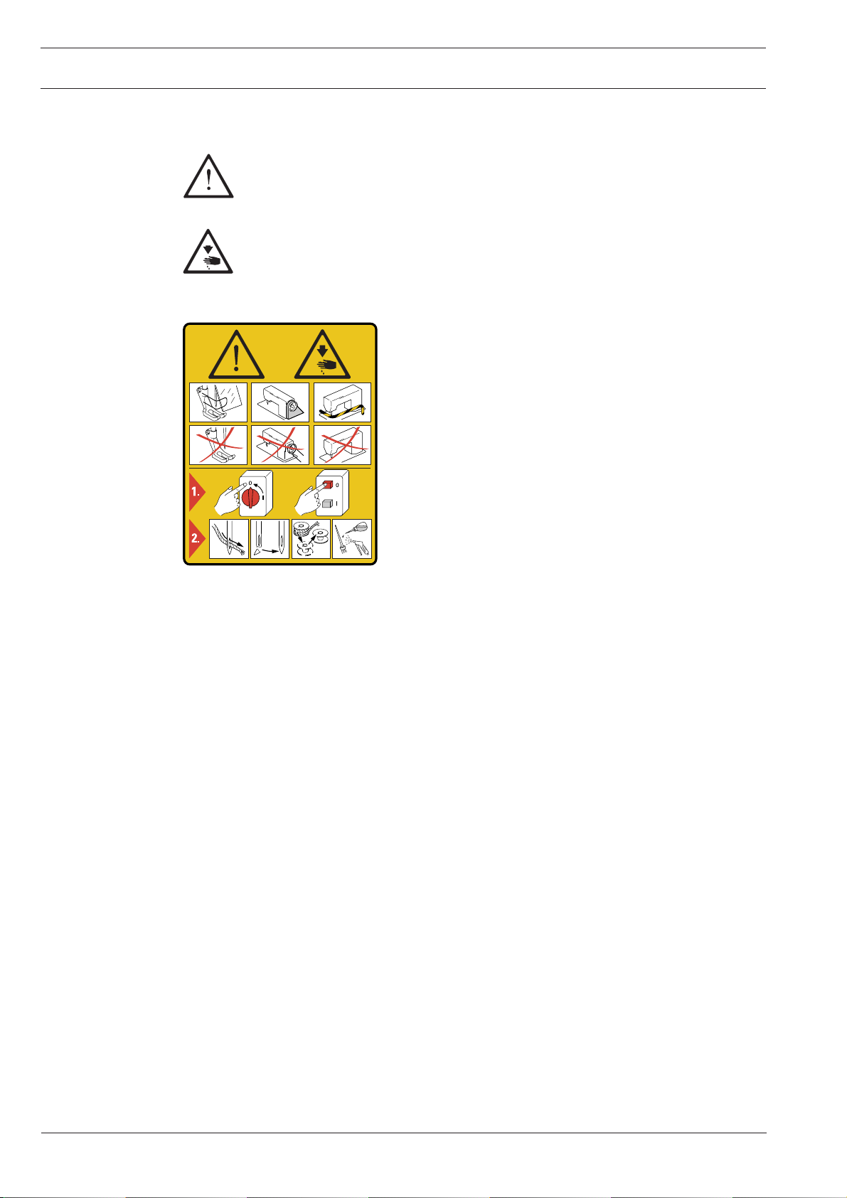
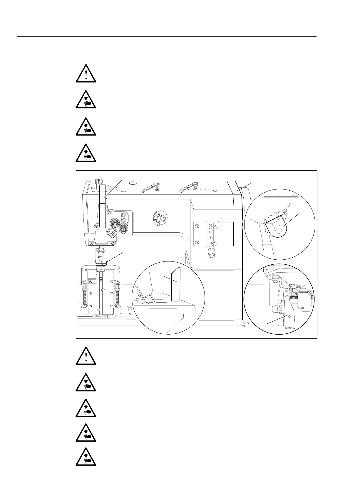
1.06 Danger warnings
A working area of 1 m must be kept free both in front of and behind the
machine, so that easy access is possible at all times.
Never put your hands or fingers in the sewing area during sewing!
Danger of injury by the needle!
While setting or adjusting the machine do not leave any objects on the table nor
in the needle plate area! Objects may be trapped or flung out of the machine!
When a mechanically operated clutch motor without actuation lock is switched
off, alwys wait until the motor has stopped! Danger of injury!
Fig. 1 - 01
2
4
5
0
1
2
3
3
1
6
1 - 4
Do not run the machine without support 1.
Danger due to top-heavy sewing head!
Machine may tip over backwards when tilted!
Do not run the machine without take-up lever guard 2!
Danger of injury by moving take-up lever!
Do not run the machine without finger guard 3!
Danger of injury by up and down movement of needle!
Do not run the machine without belt guards 4 and 5!
Danger of injury by rotating v-belt!
Do not operate the machine without tilt lock 6!
Danger of crushing between sewing head and table!

2 Proper use
The PFAFF 1295 is a single-needle lockstitch postbed sewing machine with unison feed and
large vertical sewing hook.
The PFAFF 1296 is a two-needle lockstitch postbed sewing machine with unison feed and
large vertical sewing hooks.
These machines are for sewing lockstitch seams in the textile industry.
Proper use
Any use of this machine which is not approved by the manufacturer shall be
considered as improper use! The manufacturere shall not be held liable for any
damage arising out of improper use! Proper use shall also be considered to
include compliance with the operation, adjustment, service and repair
measures specified by the manufacturer!
2 - 1

Specifications
3 Specifications
3.01 PFAFF 1295, PFAFF 1296
Stitch type: .................................................................................................. 301 (lockstitch)
Needle system ........................................................................................................134 - 35
Needle size in 1/100 mm: ...................................................................................... 110 - 140
▲
Max. thread size (synthetic
Max. stitch length:
Version CN : ............................................................................................................ 6,0 mm
Version CN 11 : ..................................................................................................... 11,0 mm
Effective dia. of balance wheel: ............................................................................... 90 mm
Dimensions of the machine:
Length: ...................................................................................................... approx. 530 mm
Breadth:: ................................................................................................... approx. 177 mm
Height (above table): ................................................................................. approx. 440 mm
Clear workspace length: ......................................................................................... 265 mm
Clear workspace height: ......................................................................................... 115 mm
Fabric clearance (with presser foot raised): .............................................................. 14 mm
Postbed height: ...................................................................................................... 165 mm
): ...................................................................................... 20/3
◆
Net weight (sewing head): .......................................................................................... 55 kg
Motor data: ............................................................................see motor specification plate
Working pressure: ....................................................................................................... 6 bar
Air consumption: ..............................................................................~0,8 l litres/work cycle
Noise data:
Emission sound level at the workplace at appropriate speed
(Noise measurement in accordance with DIN 45 635-48-A-1, ISO 11204, ISO 3744, ISO 4871)
PFAFF 1295, model C at a speed of 1600 spm.: ........................................ L
PFAFF 1296, model C at a speed of 1500 spm.: ........................................ L
◆
Subject to technical alterations
▲
Or comparable sizes of other thread types
■
K
= 2,5 dB
pA
pA =
pA =
77 dB(A)
76 dB(A)
■
■
3 - 1

3.02 Possible versions and subclasses
Version CN; CN 11 : ................................................... For sewing medium-heavy materials
Work aids:
Subclass -900/56 ......................................................................................... Thread trimmer
Subclass -911/97 ................................Automatic presser foot lift with backtacking system
3.03 Maximum speeds of the PFAFF 1295
Specifications
Top feed stroke
Up 5,5 mm
over 5,5 mm to 7 mm
up 5,5 mm
over 5,5 mm bto 7 mm
Version
CN 11
CN 11
3.04 Maximum speeds of the PFAFF 1296
Top feed stroke
Needle gauge
CN
CN
Version
Max. speed (s.p.m.)
1900
1800
1000
800
Max. speed (s.p.m.)
Up 5,5 mm
over 5,5 mm
up 10 mm
from 10,4 mm
up 10 mm
from 10,4 mm
CN
CN
CN
CN
1800
160 0
160 0
140 0
3 - 2

Disposal of Machine
4 Disposal of Machine
● Proper disposal of the machine is the responsibility of the customer.
● The materials used for the machine are steel, aluminium, brass and various plastic
materials.
The electrical equipment comprises plastic materials and copper.
● The machine is to be disposed of according to the locally valid pollution control regula-
tions; if necessary, a specialist ist to be commissioned.
Care must be taken that parts soiled with lubricants are dispoed of separately
according to the locally valid pollution control regulations!
4 - 1

Transportation, packing and storage
5 Transportation, packing and storage
.01 Transportation to customer's premises
5
The machines are delivered completely packed.
5.02 Transportation inside the customer's premises
The manufacturer cannot be made liable for transportation inside the customer's premises
nor to other operating locations. It must be ensured that the machines are only transported
in an upright position.
5.03 Disposal of packing materials
The packing materials of this machine comprise paper, cardboard and VCE fibre. Proper dis-
posal of the packing material is the responsibility of the customer.
5.04 Storage
If the machine is not in use, it can be stored as it is for a period of up to six months, but It
should be protected against dust and moisture.
If the machine is stored for longer periods, the individual parts, especially the surfaces of
moving parts, must be protected against corrosion, e.g. by a film of oil.
5 - 1
Explanation of symbols
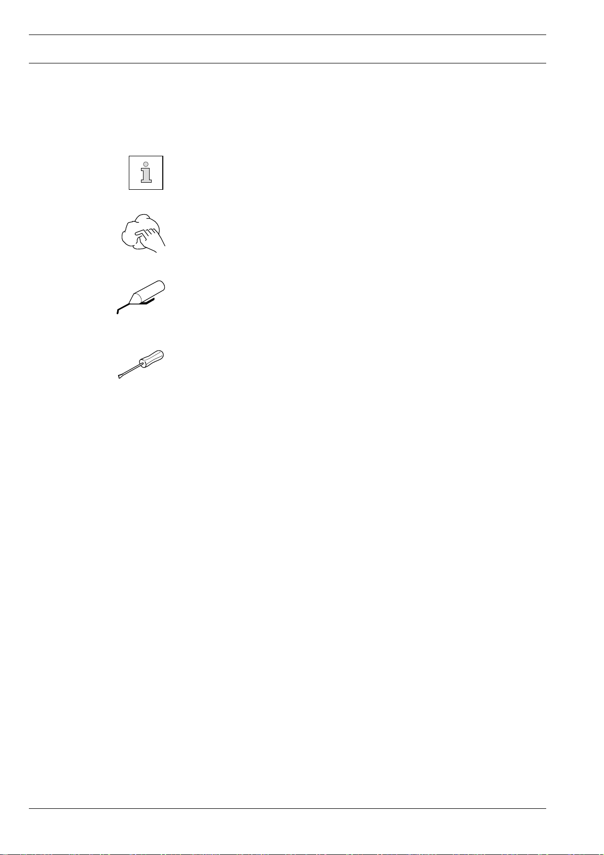
6 Explanation of symbols
In this instruction manual, work to be carried out or important information is accentuated by
symbols. These symbols have the following meanings:
Note, information
Cleaning, care
Lubrication
Maintenance, repairs, adjustment, service work
(only to be carried out by technical staff)
6 - 1
7 Controls
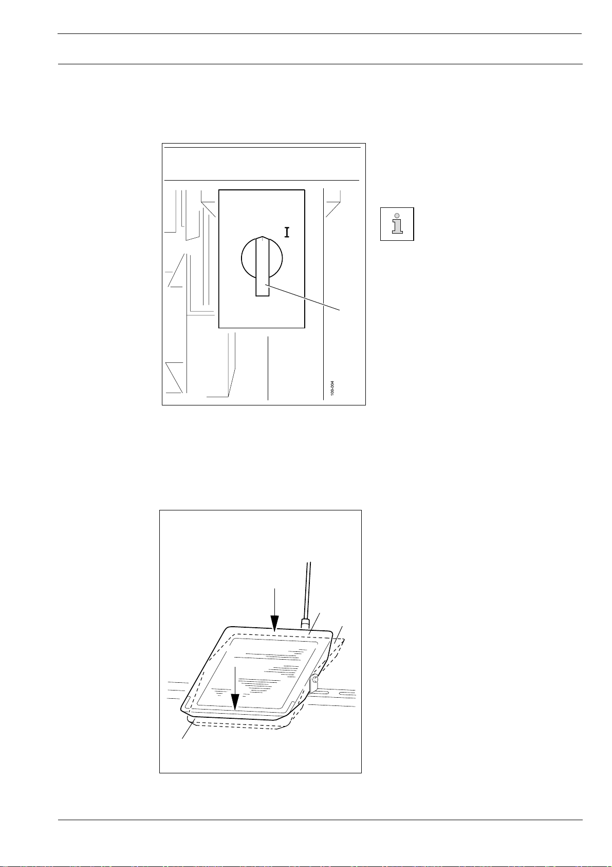
.01 On/off switch
7
Controls
● The power supply to the machine is
switched on or off by turning switch 1.
The illustrated on/off switch is
fitted to machines with Quick
motors. If other motors are
used, a different switch may be
fitted.
1
Fig. 7 - 01
7.02 Pedal (on machines without subclass -911/97)
0 = Neutral position
+1 = Sewing
-1 = Thread trimming (on machines with
0
+1
thread trimmer)
-1
Fig. 7 - 02
7 - 1

Controls
7.03 Pedal (on machines with subclass -911/97)
0 = Neutral position
+1 = Sewing
-1 = Raise presser foot
0
+1
-2 = Thread trimming (on machines with
thread trimmer)
-1
-2
Fig. 7 - 03
7.04 Knee lever (on machines without subclass -911/97)
● The presesr foot is raised by pressing
knee lever 1.
7 - 2
1
Fig. 7 - 04

7.05 Key on machine head (on machines with subclass -911/97)
● If key 1 is pressed during sewing, the
machine will switch to reverse sewing.
1
Controls
Fig. 7 - 05
7.06 Presser bar lifter
1
● The presser foot is lifted by raising pres-
ser bar lifter 1.
Fig. 7 - 06
7 - 3

Controls
7.07 Feed regulator/reverse sewing
● The stitch length is adjusted by turning
the knurled nut on lever 1.
● To reverse the sewing direction press
lever 1 fully upwards.
0
1
2
3
1
Fig. 7 - 07
7.08 Feed regulator (on machines with subclass -911/97)
● Turn knurled screw 1 to adjust the stitch
length for sewing forwards.
● Turn knurled screw 2 to adjust the stitch
length for sewing backwards.
2
Reverse stitches can be set as
long as required, independently
of forward stitches.
7 - 4
1
Fig. 7 - 08

7.09 Adjusting nut for the top feed stroke
2
3
-
+
1
Controls
Switch the machine off!
Danger due to unintentional
starting of the machine!
● Loosen screw 1 at the back of the
machine.
● Open cover 2.
● Loosen screw 3 and adjust lever
accordingly.
● Close cover 2 and tighten screw 1.
Fig. 7 - 09
7.10 Control panel (only on machines with Quick-Eco drive)
The description can be found in the separate instruction manual for the control panel.
7 - 5

Installation and commissioning
8 Installation and commissioning
The machine must only be mounted and commissioned by qualified personnel!
All relevant safety regulations are to be observed!
If the machine is delivered without a table, it must be ensured that the frame
and the table top which you intend to use can hold the weight of the machine
and the motor. It must be ensured that the supporting structure is sufficiently
sturdy, including during all sewing operations.
8.01 Installation
The site where the machine is installed must be provided with suitable connections for the
electric current, see Chapter 3 Specifications.
It must also be ensured that the standing surface of the machine site is firm and horizontal,
and that sufficient lighting is provided.
The method of packaging used requires that the table top be lowered for
transport. The following is a description of how to adjust the height of the table
top.
8.01.01 Adjusting the table-top height
1
1
2
8 - 1
Fig. 8 - 01
● Loosen screws 1 and 2 and set the desired table-top height
● Tighten screws 1 well.
● Adjust the position of the pedal so that you can operate it comfortably and tighten
screw 2.

Installation and commissioning
109-001
8.01.02 Assembling the motor (only on machines with Quick-motor)
1
4
2
3
Fig. 8 - 02
● Assemble motor mounting 1, motor 2, belt guard support 3 and belt pulley 4 as shown in
Fig. 8-02.
8.01.03 Tightening the V-belt
● Fit the V-belt.
● Loosen nut 1 and tighten the V-belt by
turning motor mounting 2.
● Tighten nut 1.
1
Fig. 8 - 03
2
109-020
8 - 2

Installation and commissioning
8.01.04 Mounting the bottom V-belt guard
4
2
3
2
Fig. 8 - 04
● Loosen screws 2 and adjust belt guard support 1 so that the motor pulley and V-belt run
freely.
● Tighten screws 2.
● Fasten belt guard 3 with screw 4.
Fig. 8-04 shows a Quick-motor. If a different motor is used, follow the
instructions of the Motor Instruction Manual.
1
8 - 3

8.01.05 Fitting the upper belt guard
Installation and commissioning
6
5
6
8
Fig. 8 - 05
1
4
● Screw stop piece 2 onto belt guard part 3.
● Screw on belt guard part 3 with screws 4.
2
3
8
7
● Screw on belt guard part 5 with screws 6.
● Secure belt guard part 7 to the table top
using woodscrews 8.
If a large balance wheel is in
use, break off corner 1 of belt
guard part 3.
8
4
8.01.06 Fitting the synchronizer
1
2
Fig. 8 - 06
● Push synchronizer 1 onto the shaft so
that stop 2 is standing in the slot on the
synchronizer (see arrow)
● Tighten screws 3.
● Connect the synchronizer plug to the
control box.
● Connect the synchronizer plug to the
adapter (see Chapter 8.02 Connecting
the plug connections and earth
cables).
● Adjust the synchronizer 1, see Chapter
3
8.05 Basic position of the machine.
8 - 4

Installation and commissioning
8.01.07 Fitting the tilt lock
Switch off the machine!
Danger of injury due to
unintentional starting of the
machine!
2
Fig. 8 - 07
8.01.08 Fitting the reel stand
● Screw on tilt lock 1, provided in the accessories, using screw 2.
Do not operate the machine
without tilt lock 1!
Danger of crushing between
sewing head and table top!
1
● Fit the reel stand as shown in Fig. 8 - 08.
● Afterwards insert the stand in the hole in
the table top and secure it with nuts pro-
vided.
8 - 5
Fig. 8 - 08
Table top mounting and circuit diagrams
(see Chapter 11)

Installation and commissioning
8.02 Connecting the plug-in connections and earth cables
7
B
A
5
X 2
Motor
6
Extern
1
4
2
A 14
Fig. 8 - 09
● Plug adapter cable 1 into control box 2.
● Plug the cable coming from the machine to adapter cable 1 as marked.
● Plug the cable A14 coming from adapter 1 to the sewing head recognition unit 4.
● Insert plug 5 from the adapter cable to bush X 2.
● Connect the motor to the "motor" plug and the synchronizer to the "external" plug.
● Screw the earth cable from the sewing head and the main switch to earth point A.
● Connect earth point A to earth point B with earth cable 6.
● Screw the earth cable 7 from the motor to earth point B.
8 - 6

Installation and commissioning
8.03 Commissioning
● Clean the machine thoroughly and afterwards fill it with oil and oil the machine (see
Chapter 10, Care and maintenance).
● Check the machine, particularly its electrical wiring and pneumatic tube connections, for
any damage.
● Have skilled personnel check if the machine can be operated with the available mains
voltage.
Do not operate the machine if there is any discrepancy.
Before commissioning the machine, have specialized personnel check whether
the parameter 799 (machine class) is set at "2" and the parameter 800 (sewing
direction) is set at "1". If necessary, have the adjustment carried out (see
Chapter 8.05 Basic position of the machine drive unit).
The machine may only be connected to an earthed socket!
● Connect the machine to the compressed air supply. When it is connected, the gauge
should show a pressure of approx. 6 bar. If necessary, have this reading correctly set
(see Chapter 10.06, Checking/adjusting the air pressure).
8.04 Switching the machine on/off
● Switch the machine on (see Chapter 7.01, On/off switch).
8 - 7

Installation and commissioning
8.05 Basic position of the machine drive unit
(only on machines with Quick-EcoDrive and control unit P40ED)
● Switch on the machine.
● Press the TE/speed key twice to select the input mode.
● Select parameter "798" by pressing the corresponding +/- key, and select service level
C, see Chapter Selecting the user level in the instruction manual for the control panel.
● By pressing the corresponding +/- key select the parameter "799" (Selecting the machine
class).
● Check whether value "2" is set, and correct it if necessary.
If the parameter has to be altered, operate the TE/Speed key and then switch
off the machine and switch it on again. Then select service level C again as
described above.
● By pressing the corresponding +/- key, select parameter "800" (selecting the sewing
direction).
● By pressing the corresponding +/- key, select the value for the parameter at "1".
● By pressing the corresponding +/- key, select parameter "700".
● Sew a stitch by operating the pedal.
● Turn the balance wheel in the sewing direction until the descending needle is level with
the top edge of the needle plate.
● Then check the parameter values listed in the parameter list (see Chapter
10.08 Parameter Settings) and adjust them if necessary.
● Conclude the adjustment of the sewing motor by pressing the TE/Speed key.
8 - 8

Setting up
9 Setting up
9.01 Inserting the needle on the bei der PFAFF 1295
All instructions and regulations in this instruction manual must be observed.
Special attention must be given to all safety regulations!
All setting-up work must only be done by personnel with the necessary training. For all setting-up work the machine must be isolated from its power supply
by turning off the on/off switch or removing the machine plug from the electric
power socket!
Switch the machine off!
Danger due to unintentional
starting of the machine!
Only use needles from the
system intended for the
machine, see Chapter 3
Specifications.
Fig. 9 - 01
● Set needle bar at top position and loosen
screw 1.
● Push needle 2 fully in (the long needle
1
2
The choice of needle depends on the version of the machine and the sewing
thread and material in use (see Chapter 3, Specifications).
groove must face to the left).
● Tighten screw 1 again.
9 - 1

9.02 Inserting the needles on the PFAFF 1296
● Set needle bar at top position and loosen
● Push needles 2 fully in (the long groove
1
● Tighten screws 1 again.
Setting up
Switch the machine off!
Danger due to unintentional
starting of the machine!
Only use needles from the
system intended for the
machine, see Chapter 3
Specifications.
screws 1.
of the left needle must face to the right
and that of the right needle to the left).
Fig. 9 - 02
2
The choice of needle depends on the version of the machine and the sewing
thread and material in use (see Chapter 3, Specifications).
9 - 2

Setting up
.03 Winding the bobbin thread, regulating the winder tension
9
4
-
+
6
1
3
5
2
Fig. 9 - 03
● Place an empty bobbin 1 on winder spindle 1.
● Thread up as shown in Fig. 9-03 and wind the thread a few ttimes clockwise around
bobbin 1.
● Engage the bobbin winder by pressing spindle 2 and lever 3 simultaneously
The bobbin is wound during sewing.
● The bobbin winder will stop when sufficient thread is wound onto bobbin 1.
If the thread is wound on unevenly:
● Loosen nut 5.
● Turn thread guide 6 as required.
● Tighten nut 5 again.
9 - 3

9.04 Changing the bobbin
Setting up
Switch the machine off!
Danger due to unintentional
starting of the machine!
2
Removing the bobbin case:
● Set the take-up lever at its highest point.
● Remove the post cover, lift latch 1 and
take out bobbin case 2.
1
Inserting the bobbin case:
● Insert bobbin case 2 so that you feel it
snap in place.
● Push latch 1 down and close the post
cover.
Fig. 9 - 04
Do not run the machine with the post cover open!
Danger of injury by moving parts!
9.05 Threading the bobbin thread and regulating the bobbin thread tension
Fig. 9 - 05
Switch off the machine!
Danger of injury due to
unintentional starting of the
machine!
5 cm
+
1
-
● Thread the bobbin as shown in Fig. 9-05.
● When the thread is pulled, the bobbin
must rotate as shown by the arrow.
● Regulate the bobbin thread tension on
srew 1.
9 - 4

Setting up
9.06 Threading needle thread/adjusting needle thread tension on the PFAFF 1295
1
9 - 5
Fig. 9 - 06
Switch off the machine!
Danger of injury due to unintentional starting of the machine!
● Thread needle thread as shown in Fig. 9-06. Be sure to thread the needle from the left.
● Regulate the needle thread tension by turning knurled screw 1.

Setting up
9.07 Threading needle thread/adjusting needle thread tension on the PFAFF 1296
2
1
Fig. 9 - 07
Switch off the machine!
Danger of injury due to unintentional starting of the machine!
● Thread needle threads as shown in Fig. 9-07. Be sure to thread the right needle from the
left and the left needle from the right.
● Regulate the needle thread tensions by turning knurled screw 1 (right needle) or 2 (left
needle).
9 - 6

Setting up
9.08 Adjusting the stitch counter for the bobbin thread control
(only on machines with Quick Motor and P40 (ED) control unit)
Please see the description in the separate control panel instruction manual.
9 - 7

10 Care and maintenance
Check air pressure ......................................................... daily, each time before operation
Clean hook area ............................................ daily, in continuous operation several times
Check water bowl of air filter/regulator .......................................... daily, before operation
Oil hook ...................................................................................................................... daily
General oiling ............................................................................................... twice a week
Oil needle-head parts ................................................................................... twice a week
Clean hook .................................................................................................... once a week
Lubricate top-feed drive eccentric ................................................................. once a week
The maintenance intervals in the table refer to the average machine running
time in single-shift operation. If the machine running time is longer than this, it
is advisable to shorten these intervals.
Care and maintenance
10.01 Cleaning
Fig. 10 - 01
Switch off the machine!
Danger of injury due to
3
5 mm
2
1
● Clean hook area with a brush daily, in
continuous operation several times daily.
● Clean the hook thoroughly once a week.
● Open post cover.
● Set needle bar at its highest position.
● Remove top of bobbin case together
with bobbin
● Unscrew and remove hook gib 1.
● Turn balance wheel until point of bobbin
case 2 has entered into the groove of the
hook race by about 5 mm.
● In this position remove bobbin case 2.
● Clean hook race with petroleum spirit.
unintentional starting of the
machine!
● When inserting the bobbin case, make sure that bobbin case position finger 3 enters the
slot in the needle plate.
● Screw on hook gib 1.
● Insert bobbin case and close post cover.
10 - 1

Care and maintenance
10.02 Ölen allgemein
0
1
2
3
Fig. 10 - 02
● Apply oil at all bearing points above the table (see arrows) twice a week.
Switch off the machine!
Danger of injury due to unintentional starting of the machine!
● Pull knee lever out to the front and tilt machine backwards.
● Apply oil at all bearing points beneath the table (see arrows) twice a week.
10 - 2
Set the machine upright with both hands! Danger of crushing between sewing
head and table!

Care and maintenance
Only use oil with a medium viscosity of 22.0 mm²/s at 40° C and a density of
0.865 g/cm³ at 15°C!
We recommend PFAFF sewing-machine oil, part No. 280-1-120 144.
10.03 Oiling the sewing hook
Fig. 10 - 03
Switch off the machine!
Danger of injury due to
unintentional starting of the
machine!
● Open the post cover.
● Set the needle bar at its highest position.
● Apply 1 or 2 drops of oil in hole 1 of the
hook gib.
● Apply a few drops of oil to the hook race
(see arrow)
Only use oil with a medium
viscosity of 22.0 mm²/s at 40°
C and a density of 0.865 g/cm³
at 15°C!
1
We recommend PFAFF sewing-
machine oil, part
No. 280-1-120144.
10 - 3

Care and maintenance
10.04 Oiling the needle-head parts
Fig. 10 - 04
Switch off the machine!
Danger of injury due to
unintentional starting of the
machine!
● Remove the faceplate.
● Oil all moving parts and bearing points
(see arrows) twice a week.
● Refit the faceplate.
Only use oil with a medium
viscosity of 22.0 mm²/s at 40°
C and a density of 0.865 g/cm³
at 15°C!
We recommend PFAFF sewing-
machine oil, part
No. 280-1-120144.
10.05 Lubricating the top-feed drive eccentric
2
● Loosen screw 1 and open cover 2 on the
● Apply a little grease at nipple 3 at least
● Close cover 2 and tighten screw 1.
1
3
Fig. 10 - 05
Switch off the machine!
Danger of injury due to
unintentional starting of the
machine!
rear side of the machine.
once a year.
Only use lithium grease with a
dripping point of 185°C and a
roll-penetration of 22 to 25 mm
at 25°C.
We recommend PFAFF sewing
machine grease, part
No. 280-1-120247.
10 - 4

10.06 Checking/regulating the air pressure
2
8
6
4
50
2
0
10
100
150
12
200
14
230
0
16
1
Care and maintenance
● Check the air pressure on gauge 1 every
time before operation.
● Gauge 1 must show a pressure of 6 bar.
● Regulate this pressure if required.
To do so, pull knob 2 up and turn it
accordingly.
Fig. 10 - 06
10.07 Emptying/cleaning the water bowl of the air filter/regulator
Switch off the machine.
Disconnect the air hose at the
air filter/regulating unit.
Emptying the water bowl
8
6
4
2
0
10
100
150
50
0
12
200
14
230
16
● Water bowl 1 empties itself automatically
when the air hose is disconnected from
the air filter/regulator.
Cleaning the filter
● Unscrew water bowl 1 and take out filter 2.
● Clean the filter with compressed air or
max.
2
with isopropyl-alcohol, part number
95-665735-91.
● Screw in filter 2 and screw on water bowl 1.
1
Fig. 10 - 07
10 - 5

Care and maintenance
10.08 Parameter settings
(only on machines with Quick-EcoDrive and control unit P40ED)
● The selection of the user level and the alteration of parameters is described in the separa-
te instruction manual for the drive unit.
10.08.01 Parameter list
Group
Parameter
Description
User lever
Setting
range
1 105 Speed for start backtack B, C 300 - 2000 600
110 Speed for end backtack B, C 300 - 2000 800
6 607 Speed max. B, C 300 - 6000 ▲
609 Cutting speed 1 B, C 60 - 300 180
7 700 Needle position 0 B, C 0 - 255 *
(needle reference position)
702 Needle position 1 (needle lowered) B, C 0 - 255 80
703 Needle position 2 (take-up lever raised) B, C 0 - 255 225
705 Needle position 5 (end cutting signal 1) B, C 0 - 255 100
706 Needle position 5 (start cutting signal 2) B, C 0 - 255 80
707 Needle position 9 (start thread tension B, C 0 - 255 195
release/start thread catcher)
Set value
10 - 6
722 Acceleration ramp B,C 1 - 60 45
723 Brake ramp B,C 1 - 60 40
734 Tact output A2 (thread trimming) B,C 001 - 009 0
760 Multiplier for the fixed value (200) for A, B, C 0 - 250 5
stitch count
799 Selected machine class C 1 - 4 2
▲
See Chapter 3 Specifications
*
Adjustment see Chapter 8.05 Basic position of the machine drive unit .

Care and maintenance
Group
8 800 Rotating direction of the motor C 0 - 1 1
9 900 Additional P- sensitivity of the B,C 1 - 24 10
Parameter
884 Proportional sensitivity of the B,C 03 - 24 12
897 Variant mini-motor, 1 = long, 2 = short C 0 - 1 1
Description
speed control unit
1295 B,C 03 - 24 12
1296 B,C 03 - 24 16
speed control unit
Further parameters and the description for an internet update of the machine
software and reset /cold start of the machine can be found in the instruction
manual for the control panel.
User lever
Setting
range
Set value
10 - 7

Mounting the table top
11.01 Table top cutout
906-7000-405
11 - 1

11.02 Mounting the table top
Stand position
906-3750-005/895
Mounting the table top
Drillholes for fastening
the motor (Screwed
inserts M8 x 30 )
Holes for fastening
the knee lever
P 40 ED
Speedcontrolunit
Controlbox
91-141 939-95
Vers. 30.03.06
View:
Underside table top
11 - 2

Circuit diagrams
11.03 Circuit diagrams
Reference list for the Circuit diagrams
A1 Control unit Quick P40 ED
A2 Control panel BDF S2
A14 Sewing head recognition system (OTE)
H1 Sewing lamp (optional)
H10 LED stitch counter
M1 Sewing motor
Q1 Main switch
S1 Manual backtacking key
S1.1 Pedal speed control unit
S2 Needle position change key
S3 Single stitch key
S6 Start inhibitor (E6 stop)
X0 PC-interface (RS 232)
X1 Motor
X2 Incremental transducer
X2.1 Incremental transmitter adapter
X2.2 Synchronizer adapter
X2.3 Y5-911/.. backtacking device
X3 Speed control unit
X3.1 Y2-900/.. thread trimmer (FS )
X4 A2 control panel plug BDF S2
X4.1 Y4 -910/.. automatic foot lift
X5 Out-/input
X6 Bobbin thread monitor (optional)
X6.1 Y8 Thread tension release
X7 Photoelectric barrier (optional)
X22 Y2 -900/.. thread trimmer (FS )
X24 Y4 -910/.. automatic foot lift
X25 Y5 -911/.. backtacking device
X28 Y8 Thread tension release
X40 S1-3 Control panel
X50 A14 Sewing head recognition system (OTE)
11 - 3
Y2 -900/.. thread trimmer
Y4 -910/.. automatic foot lift
Y5 -911/.. backtacking device
Y8 Thread tension release

91-191 502-95
Page 1 Version 07.07.06
Circuit diagram
11 - 4

Circuit diagram
Version 07.07.06
91-191 502-95
Page 2
11 - 5

91-191 502-95
Page 3 Version 07.07.06
Circuit diagram
11 - 6

Wearing parts
12 Wearing parts
This is a list of the most important wearing parts.
A detailed parts list for the complete machine is included with the accessories.
In case of loss, the parts list can be downloaded from the internet address
www.pfaff-industrial.com/pfaff/de/service/downloads As an alternative to
the internet download the parts lists can also be ordered in book form
under part no. 296-12-18 639.
91-100 366-15 91-000 085-15
91-000 277-25 (2x)
91-000 781-15
91-018 340-91
91-018 285-91 (-900/56)
91-018 348-91
91-018 676-9 (-900/56)
91-019 891-05 (-900/56)
91-018 346-01
91-018 649-01 (-900/56)
91-173 664-15
91-000 390-05 (2x)
91-018 349-05
91-018 682-05 (-900/56)
91-018 341-91
System 134 - 35
91-000 390-05
91-000 525-15
91-018 399-05
91-018 480-05 (-900/56)
12 - 1
91-000 529-15 (3x)
91-018 439-05
91-018 293-05
91-018 344-05

99-137 151-45
Wearing parts
91-171 049-05
91-018 257-05
91-171 042-05
95-774 464-25
91-700 996-15
11-039 171-15
12-315 110-15
91-011 957-15
91-701 344-15 (2x)
12 - 2

PFAFF Industriesysteme
und Maschinen AG
Hans-Geiger-Str. 12 - IG Nord
D-67661 Kaiserslautern
Telefon: +49 - 6301 3205 - 0
Telefax: +49 - 6301 3205 - 1386
E-mail: info@pfaff-industrial.com
Gedruckt in der BRD / Printed in Germany / Imprimé en la R.F.A. / Impreso en la R.F.A
© PFAFF Industriesysteme und Maschinen AG 2009, PFAFF is the exclusive trademark of VSM Group AB.PFAFF Industriesysteme und Maschinen AG is an authorized licensee of the PFAFF trademark.
 Loading...