

Page 1
Practical Instrument Electronics
Model 535
4-20/10-50 mA/V Loop Calibrator
82 E. Main Street Suite 3.14 • Webster, NY 14580
Tel: 585-872-9350 • Fax: 585 -872-2638
sales@piecal.com • http://www.piecal.com/
Practical Instrumen t Electro nics, Inc. Copyr i ght 2011. All rights reserved.
1-8
j
k
l
m
n
†
‡
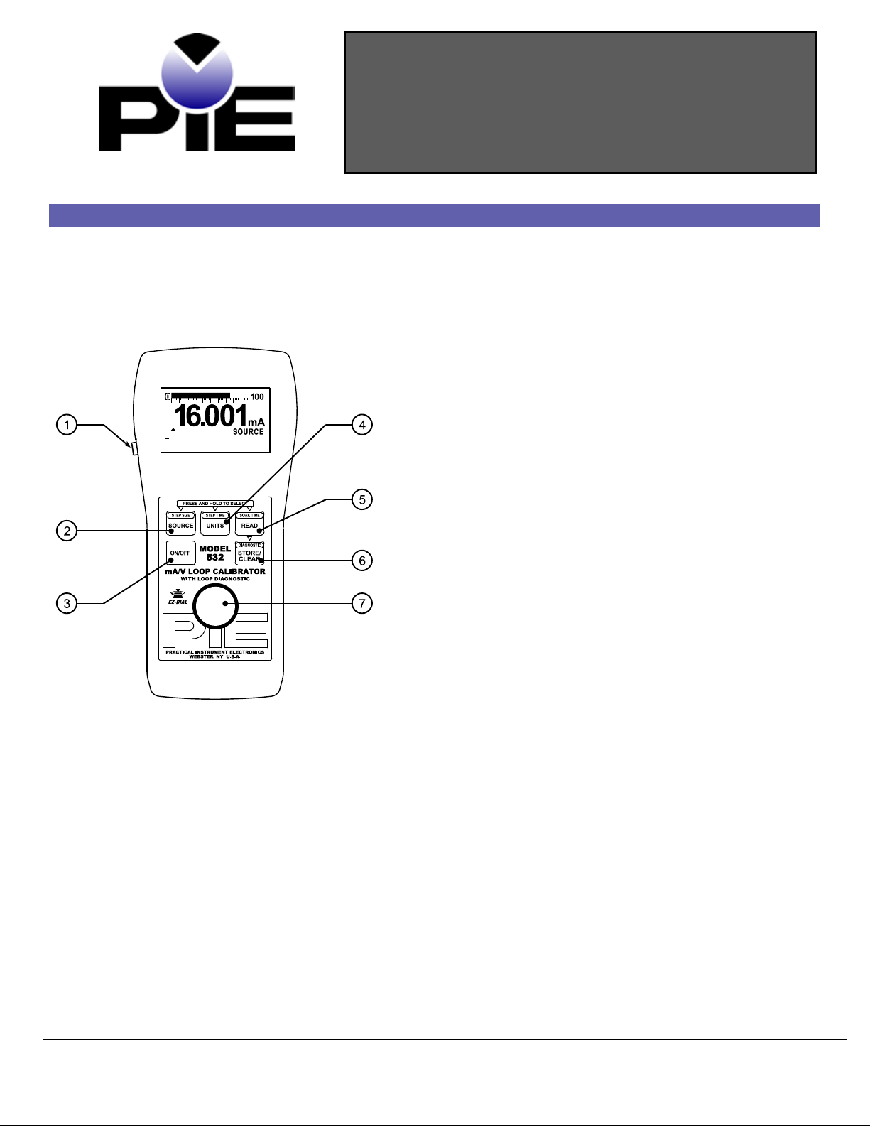
Basic Keypad Operations
EZ-Check™ Switch/EZ-Step™ Pushbut ton
Slide the switch to sele ct the u ser stored values fo r calib ra tion
points. Press the button to adjust the ou tp ut b y the u ser
defined step size. Press and hold the b utton to activ ate the
auto step/ramp mode.
Operati n g Instruct ions
UNITS/ STEP TIM E Button
Press and release UNITS/STE P TIME to change how current is
displayed: e ith e r in millia mp e re s or % of 4 -20/10-50 mA. Voltage
is only displayed in volts.
Press and hol d UNITS/STEP TIME to change ste p si ze.
READ/SOAK TIME Button
Press and release READ/SOAK TIME to change read modes.
These are:
• Read Milliamps
• Power and Measure 2-Wire Transmitter
• Read Volts
Press and hol d READ/SOAK TIME to change soak time.
STORE/CLEAR Button
In any source mode:
Press STORE/CLEAR to save the current reading in the EZCheck HI or LO position. The EZ-Check switch must be set to HI
or LO. The display will flash “STORED” to conf irm.
In any read mode:
Press STORE/CLEAR to clear the values saved in the EZ-Check
HI and LO positions. The display will flash “CLEARED ” to confirm.
SOURCE/STEP S IZE But t o n
Press and release SOURCE/STEP SIZ E to change source
modes. These are:
• Source Milliamps
• 2-Wire Transmitter Si mulate
• Source Volts
Press and hol d SO U R CE/STEP SIZE t o ch a n g e step size.
ON/OFF Button
Press ON/OFF to turn the Model 535 on or off .
EZ-Dial™ Knob
Turn the EZ-Dial knob to adjust the output level. Press and turn
to adjust 100X faster.
535-9002 Rev G 7/13/11
Page 2

Model 535 Operating Instru c tions
82 E. Main Street Suite 3.14 • Webster, NY 14580
Tel: 585-872-9350 • Fax: 585 -872-2638
sales@piecal.com • http://www.piecal.com/
Practical Instrumen t Electro nics, Inc. Copyr i ght 2011. All rights reserved.
2-8
Model 535 Configuration
Press the EZ -Dial Knob while turning the Model 535 on to access the configuration mode. Turn
the EZ-Dial Knob to select configuration items. Press the EZ-Dial Knob to change configuration
items. Turn the unit of f or just wai t approximately 8 seconds to exit the configuration mode.
Auto Off - ON (default)/OFF
Auto Off is ON, by defa ult, to sav e b atte ry lif e by turning the u nit of f af te r 30 minute s of ina ctivity . Turn A uto Of f to OFF to p revent
automatic shutdown. This is typically useful for manual loading or continuous use.
EZ-Step - ON/OFF (default)
If EZ-Step is ON manual and automatic step p in g /ra mp ing is available . If EZ-Step is OFF the EZ-Step pushbutton will be disabled
and the step d ire ction in d icator wi ll not be display e d .
EZ-Check HI/LO Readings ON/OFF (default)
If the EZ-Check HI/LO Readings option is ON, the highest a nd l owe st re ad in g s will a utomatically b e sav e d in the HI and LO EZ Check™ positions.
If this option is OFF the HI and LO positions will sh ow th e current reading.
4-20/10-50 Range (default) ON
Select either 4-20 or 10-50 milliamp range. The Model 535 scales % mode display and the bar graph accordingly.
Factory Reset ON/OFF (default)
If Factory Reset is ON, t he un it will re store all factory de f a ults wh e n th e Model 535 is turned OFF and back ON. This will reset a ny
changes made in the Model 535 Configu rat ion op t ions, returning th e un it to its simp le st f a ctory configuration .
EZ-Dial Knob
Adjust the output up and down with the EZ-Dial knob. The increment is 0.001 mA (or 0. 01 % if display uni ts are % of 4-20/10-50
mA.) Press while turning to ad just 100X fa ster – 0.100 mA (or 1.00 %.)
EZ-Check Switch
The EZ-Check™ swi tch h a s three posit io ns -- high, set, and low. Its positi on is shown at the left edge of the disp lay with “HI” and
“LO” indicat ors. Use of the E Z -Check swit ch d e pends on mode:
Source Modes:
Slide the EZ-Check switch to the HI and LO positions to rec all t he se ttings stored in those positio ns. While in the HI and LO
positions, dial the E Z -Dial knob to change the display. Press STORE/CLEAR to save new settings in the HI and LO posi t io n s. The
display will flash “S TORED” to confirm.
Hint: For faster calibrations, the position of the switch can be f e lt. This fe a ture a llows continuous monito ring of the device being
calibrated without looking back at the Mode l 535 display. This is also useful in poor lighting or und e r d ifficult operating conditions.
Read Modes:
In read modes, the Mode l 53 5 calib rator records the ma x imum and minimum re adings observed in e a ch mod e . S lid e the EZ -Check
switch to the HI and LO positions to display the re a dings. Pre ss STORE/CLEAR to clear the reading s. The display will f lash
“CLEARED” to confirm. B y d e fault, the Model 535 has EZ-Check HI/LO Readings OFF.
EZ-Step Pushbutton/ Manual Step
The EZ-Step pushbutton is a feature only in source modes.
Press and hold the EZ-Step pushbutton for less than one second to cause the output to step up or down by the EZ-Step size.
The EZ-Step direction is indicated on the displa y ( or ). Press the EZ-Dial knob to change the step direction.
Stepping and auto step/ramp limits are defined by the EZ-Check HI and LO settin g s. The ste p direction change s wh e n a limit is
reached.
The step size is computed as the difference between the EZ-Check HI and the EZ-Check LO divided by the number of steps. See
figure 1. By default, the Model 535 has EZ-Step OFF.
535-9002 Rev G 7/13/11
Page 3

Model 535 Operating Instru c tions
82 E. Main Street Suite 3.14 • Webster, NY 14580
Tel: 585-872-9350 • Fax: 585 -872-2638
sales@piecal.com • http://www.piecal.com/
Practical Instrumen t Electro nics, Inc. Copyr i ght 2011. All rights reserved.
3-8
0
4
8
12
16
20
24
1 2 3 4 5 6 7 8 9 10 11 12 13 14 15
time
mA
time
soak tim e
step size = (EZ-Step HI – EZ-Step LO) ÷ # of steps
step time = ramp time ÷ # of
Auto Step/Ramp
Press the EZ -Step pushbutton f or more th an one se cond to a ctiva te auto step/ramp mode. The Model 535 will aut omatically step by
the selected EZ-Step size and time. Press the EZ-Step p ushbutton aga in to d e activ ate au to step /ramp mod e .
The EZ-Step direction is indicated on the displa y ( or ). Press the EZ-Dial knob to change the step direction. The step
direction can be chang e d while automatically ste p p in g /ra mp ing.
Stepping and auto step/ramp limits are defined by the EZ-Check HI and LO settin g s. The ste p direction change s wh e n a limit is
reached.
Figure 1 will show how the Step/Ramp Parame te rs are use d t o conf ig u re au tomat ic stepping/ramping.
Figure 1
ramp
Note: The Model 535’ s ab ilit y to detect overload/undervoltage condition s may be limited by the rate of change in the output when
using automatic stepping/ramping. Turn auto step/ramp off while connecting or disconnecting the Model 535.
The Quick Reference Bar Graph indicates the input and output level on the Model 535 in % of 4-20/10-50 mA with 1% resolution.
Quick Reference Bar Graph
535-9002 Rev G 7/13/11
Page 4

Model 535 Operating Instru c tions
82 E. Main Street Suite 3.14 • Webster, NY 14580
Tel: 585-872-9350 • Fax: 585 -872-2638
sales@piecal.com • http://www.piecal.com/
Practical Instrumen t Electro nics, Inc. Copyr i ght 2011. All rights reserved.
4-8
To Change the EZ -Step Size:
To Change the So ak Time:
To Change the EZ -Step
TM
Direction:
Read Milli am p
Manual Step and Auto Step/Ramp Para m eter
1. Press and hold the SOURCE/STEP SIZE button for more than ¾ of a second.
2. The display will flash “EZ-S TEP SIZE”.
3. Turn the EZ-Dial knob to sele ct from 2 to 16 step s b e tween the EZ-Check limits.
4. Turn the EZ-Dial clockwise past 16 st e p s t o select continuous ramp mode.
5. Press the SOURCE/STEP SIZE button again to return to the normal display.
Note: If the EZ-Step
To Change the EZ -Step Time:
1. Press and hold the UNITS/STEP TIME button for more than ¾ of a second.
2. The display will flash “EZ-S TEP TIM E”.
3. Turn the EZ-Dial knob to sel e ct f rom 5 to 900 second ramp time . The time p e r ste p is
calculated based on the selected EZ-Step size.
4. Press the SOU R C E / ST E P SIZ E button to return to the nor mal d ispla y .
1. Press and hold the READ/SOAK TIME button for more than ¾ of a second.
2. The display will flash “SOA K TIME”.
3. Turn the EZ-Dial knob to se le ct from 0 to 900 second soak time.
Note: A soak time of 0 defeats the soak period. The step time will be used instead.
4. Press the READ/SOAK TIME button again to return to the normal display.
1. Press and release the EZ-Dial knob without turning.
option is turned of f , th e displa y w ill f lash “EZ-S TEP OFF”.
2. The display will change to show the EZ-Step direction selected ( or ).
Connect the Model 535 in se rie s with the process loop to
monitor current. Observe correct polarity. Current
limiting above 24 mA (5 2 mA if 10-50 range is selected)
is indicated by a f la shing “CURRENT LIMITED” disp la y .
Modes of Operation
535-9002 Rev G 7/13/11
Page 5

Model 535 Operating Instru c tions
82 E. Main Street Suite 3.14 • Webster, NY 14580
Tel: 585-872-9350 • Fax: 585 -872-2638
sales@piecal.com • http://www.piecal.com/
Practical Instrumen t Electro nics, Inc. Copyr i ght 2011. All rights reserved.
5-8
Read Volts
Power and Measure 2 Wire Transmitter
The Model 535 provides power to the process loop while
displaying output current. Use this mode to test a
transmitter’s ability to control loop curre n t. Curre nt
limiting above 24 mA (5 2 mA if 10-50 range is selected)
is indicated by a f la shing “CURRENT LIMITED” disp la y .
The Model 535 measures +/- 30 VDC with 4X overrange
ability. The display flashes “OVERRANGE” when the 30
volt limit is exceede d.
Connect the Model 535 directly to 4-20/10-50 mA
receiver equipment, alarms, panel meters, etc. Use the
EZ-Dial Knob and EZ-Check Switch to adjust loop
current. The display flashes “HIGH Ω” when the loop
resistance is too high o r the le a d s are op e n .
Source Mil liamp
535-9002 Rev G 7/13/11
Page 6

Model 535 Operating Instru c tions
82 E. Main Street Suite 3.14 • Webster, NY 14580
Tel: 585-872-9350 • Fax: 585 -872-2638
sales@piecal.com • http://www.piecal.com/
Practical Instrumen t Electro nics, Inc. Copyr i ght 2011. All rights reserved.
6-8
Relative Humidi ty Ra nge
10 % ≤RH ≤90 % (0 to 35 °C), Non-condensing
Battery
4 - AA Alkaline Optional 120 VAC 50/60 Hz AC ad ap tor included
2 Wire Transmitter Simulate
Substitute the Model535 f or a 2 wire tran smi tte r. Use
the EZ-Dial Knob and EZ-Check S witch to ad just loop
current. At least 2 volts of loop p ow e r is req u ire d , e lse
the displa y flashes “CHECK LOOP SUPPLY.”
Source Volts
The Model 532 sources 0.000-24.0 00 volts. Thi s i s useful
for powering transmitters and receive r equipment. Use
the EZ-Dial Knob and EZ-Check S witch to ad just
output voltage. The display flashes “LOW Ω” when the
output is overloade d .
Specifications
General Specifications:
Unless otherwise ind icate d all specifications are rated from a nomin al 23 °C, 70 % RH f or 1 year from calibration with >1 MΩ load
on external banana jack access to 10 Ω current sense (Model 535A).
Operating Tempe rat ure Ra ng e -20 to 60 °C (-5 to 140 °F)
Storage Temperature Range -30 to 60 °C (-22 to 140 °F)
10 % ≤RH≤ 70 % (35 to 60 °C), Non-condensing
Size 7.00 X 3.30 X 2.21 inches (177.8 x 83.8 x 56.1mm)
Weight 14.0 oz (397 grams)
Miscellaneous Low battery indication with nominal 1 hour of op e ra tion le f t
Over-voltage p rote ction to 120 V rms (rated for 30 seconds) or 240 Vrms (rated for 15
seconds)
Bar graph disp lay with 1% resolution of 4-20/10-50 mA sign a l sca le
High contrast graphic liq u id crystal display with 0.45” (11.4 mm) high dig its
535-9002 Rev G 7/13/11
Page 7

Model 535 Operating Instru c tions
82 E. Main Street Suite 3.14 • Webster, NY 14580
Tel: 585-872-9350 • Fax: 585 -872-2638
sales@piecal.com • http://www.piecal.com/
Practical Instrumen t Electro nics, Inc. Copyr i ght 2011. All rights reserved.
7-8
Accuracy
≤ ± (0.025 % of reading + 0.004 mA)
Temperature Effect
≤ ± 50 ppm/°C of range
Loop Compliance Voltag e
≥ 43 Volts
Loop Drive Capability
1200 Ω at 20 mA/800 Ω at 50 mA for entire battery life
Overload/Current Limit Protection
≤ 24 mA (4-20 range)/ ≤ 52.5 mA (10-50 range) nominal
Battery Life
≥ 40 hours typical
Miscellaneous
Open loop or out of comp lian ce conditions are indica t e d b y app rop ria te e rror d isp la y
Common Specifications for all Current Modes:
Ranges 0.000 to 24.000 mA, -25.00 to 125.00% of 4-20 mA
0.000 to 52.000 mA, -25.00 to 105.00% of 10-50 mA
Resolution 0.001 mA and 0.01 %
Step/Ramp Timebase Accu racy 0.01% of 4.9152 MHz
Source/Power and Measure 2-Wire Transmitter Specifications:
Miscellaneous Open loop or out of compl ian ce conditions are indicated by appropria te e rror d isp la y
Battery life in :
Source mode ≥ 18 hrs at 12 mA/≥ 9 hrs at 30 mA typical
Power measure ≥ 10 hrs at 12 mA/≥ 5 hrs at 30 mA typical
Selectable EZ-Step(s) for Source Mode/2-Wire Trans mitte r Simulation:
2 to 16 selectable step sett in gs
Step size is determined by the selected high & low ranges
Selectable time settings for stepping and soak:
STEP: 5 to 900 seconds SOAK: 0 to 900 seconds
Read mA Specifications:
Voltage Burden ≤ 2V
2-Wire Transmitte r Simulatio n Spe cif icatio ns :
Overload/Current Limit Protection ≤ 24 mA (4-20 range)/ ≤ 52.5 mA (10-50 range) nominal
Loop Voltage Lim its 2-90 VDC
Battery life ≥ 40 hour typical
Selectable EZ-Step(s) for Source Mode/2-Wire Trans mitte r Simulation:
2 to 16 selectable step sett in gs
Step size is determined by the selected high & low ranges
Selectable time settings for stepping and soak:
STEP: 5 to 900 seconds SOAK: 0 to 900 seconds
535-9002 Rev G 7/13/11
Page 8

Model 535 Operating Instru c tions
82 E. Main Street Suite 3.14 • Webster, NY 14580
Tel: 585-872-9350 • Fax: 585 -872-2638
sales@piecal.com • http://www.piecal.com/
Practical Instrumen t Electro nics, Inc. Copyr i ght 2011. All rights reserved.
8-8
Temperature Effect
≤ ± 200 ppm/°C of range
Input Resist a nce
≥ 1 MΩ
Source Range:
0.000 to 24.000 VDC
Accuracy
≤±(0.025%RDG + 0.004 V) ±50ppm/°C of range
4-20/10-50 Milliamp mA/V Loop Calibrator
Model 535
Read Volta ge Specificatio n s :
Range: 0.00 to 30.00 VDC (with 4X over range)
Resolutions 0.01 VDC
Accuracy 0.00 to 30.00 VDC ≤ ± (0.1 % of reading ±0.1 V )
Source Voltage Specifications:
Output Resi sta nce ≤0.3 Ω
Source Current ≥20.000 mA
Ordering Information:
Includes:
Calibration Test Data
NIST Traceable Certif ica te
Carrying Case
60 Hz AC adapter
Option:
50 Hz AC adapter
Option:
External banana jack access to internal 10 Ω
current sense .
020-0200 (included)
020-0102 (included)
020-0101
Model 535A
Warranty
Our equipment is g ua ran te e d a g ai nst d e f e ctive material and workmanship (e xcluding batteries) f or a p e riod o f thre e years from the
date of shipment . Cla ims under guarantee can be mad e b y returning the equipment prepaid to our factory. The equipment will be
repaired, rep lace d or a d juste d a t our op t ion. The lia b ilit y of P ractical Instrument Ele ctronics (PIE) is restri cte d to th at given under our
guarantee. No responsibility is accepted for d a mag e , loss or other expense in curre d throu g h sale or use of ou r e q uipment. Under no
condition shall Practical Instrument Ele ctronics, Inc. be liab le f or an y sp e cia l, incid e n tal or consequential damage.
535-9002 Rev G 7/13/11
 Loading...