

Page 1

Programmable displays with a wide selection of inputs and outputs for display of temperature,
volume and weight, etc. Feature linearisation, scaling,
and difference measurement functions for programming
via PReset software.
Interfaces for analogue and digital
signals as well as HART
®
signals between sensors / I/P
converters / frequency signals and control systems in Ex
zone 0, 1 & 2 and for some modules in zone 20, 21 & 22.
Galvanic isolators for analogue and digital
signals as well as HART
®
signals. A wide product range
with both loop-powered and universal isolators featuring
linearisation, inversion, and scaling of output signals.
PC or front programmable modules with
universal options for input, output and supply. This range
offers a number of advanced features such as process
calibration, linearisation and auto-diagnosis.
A wide selection of transmitters for DIN
form B mounting and DIN rail modules with analogue
and digital bus communication ranging from applicationspecifi c to universal transmitters.
Displays
Temperature
Isolation
Ex interfaces
Universal
DK
UK
FR
DE
Side 1
Page 13
Page 25
Seite 37
SIGNALS THE BEST
5331
2-Wire Programmable
Transmitter
No.5331V111-IN (0909)
From ser. no. 060160001
Page 2

2-TRÅDS
PROGRAMMERBAR TRANSMITTER
PRetop 5331
Indholdsfortegnelse
Sikkerhedsinstruktion ......................................................... 2
EF-overensstemmelseserklæring ....................................... 3
Anvendelse ......................................................................... 4
Teknisk karakteristik ........................................................... 4
Montage / installation ......................................................... 4
Applikationer ...................................................................... 5
Bestillingsskema ................................................................. 6
Elektriske specifikationer ................................................... 6
Tilslutninger ........................................................................ 10
Blokdiagram ....................................................................... 11
Programmering ................................................................... 12
Mekaniske specifikationer .................................................. 12
Montering af følerledninger ................................................ 12
Appendix:
FM Installation Drawing No. 5300Q502 ............................. 50
CSA Installation Drawing No. 533XQC03 .......................... 52
1
Page 3

EF-OVERENSSTEMMELSESERKLÆRING
Som producent erklærer
PR electronics A/S
Lerbakken 10
DK-8410 Rønde
hermed at følgende produkt:
Type: 5331
Navn: 2-Tråds programmerbar transmitter
er i overensstemmelse med følgende direktiver og standarder:
EMC-direktivet 2004/108/EF og senere tilføjelser
EN 61326-1 : 2006
For specifikation af det acceptable EMC-niveau henvises til modulets
elektriske specifikationer.
ATEX-direktivet 94/9/EF og senere tilføjelser
EN 50014 : 1997 + A1, A2, EN 50020 : 2002 og
EN 50284 : 1999
IEC 61241-0 : 2004 og IEC 61241-11 : 2005
ATEX-certifikat: KEMA 06ATEX0062 X (5331D)
Der kræves ingen ændringer i produktet for at opnå overensstemmelse med de
nye standarder:
EN 60079-0 : 2006 og EN 60079-11 : 2007
Bemyndiget organ
KEMA Quality B.V. (0344)
Utrechtseweg 310, 6812 AR Arnhem
P.O. Box 5185, 6802 ED Arnhem
The Netherlands
Rønde, 24. februar 2009 Peter Rasmussen
Producentens underskrift
3
Sikkerhedsinstruktion
Ex-installation:
For sikker installation af 5331D i eksplosionsfarligt område skal følgende over-
holdes. Installation må kun foretages af kvalificeret personale, der er bekendt
med de nationale og internationale love, direktiver og standarder, der gælder
for området.
Produktionsår fremgår af de to første cifre i serienummeret.
Følerkredsløbet er ikke ufejlbarligt galvanisk isoleret fra indgangskredsløbet,
men den galvaniske isolation mellem kredsene kan modstå en testspænding
på 500 VAC i 1 minut.
Transmitteren skal monteres i et hus, der giver en tæthedsgrad på mindst IP20.
I eksplosive atmosfærer forårsaget af en blanding af luft og støv:
Transmitteren må kun installeres i områder med potentiel eksplosionsfare på
grund af brændbart støv, når modulet et monteret i et form B hus i overensstemmelse med DIN 43729. Huset skal have en tæthedsgrad på mindst IP 6X
i overensstemmelse med EN 60529 og skal være egnet til den pågældende
applikation samt være installeret korrekt.
Der må kun anvendes kabelforskruninger og blindstik, som egner sig til den
pågældende applikation og som installeres korrekt.
Hvis omgivelsestemperaturen ≥ 60°C, skal der bruges varmebestandige kabler
med specifikationer på mindst 20K over omgivelsestemperaturen.
Særlige betingelser for sikker anvendelse:
Hvis huset, hvori transmitteren er monteret, er lavet af aluminium og installeret i
zone 0, 1 eller zone 20, 21 eller 22, må det i vægt højest have et totalindhold
af 6% magnesium og titanium.
Den omgivende kapsling skal konstrueres / installeres således, at der selv ved
sjældent opstående hændelser ikke er risiko for antændelse på grund af stød
og friktionsgnister.
2
Page 4
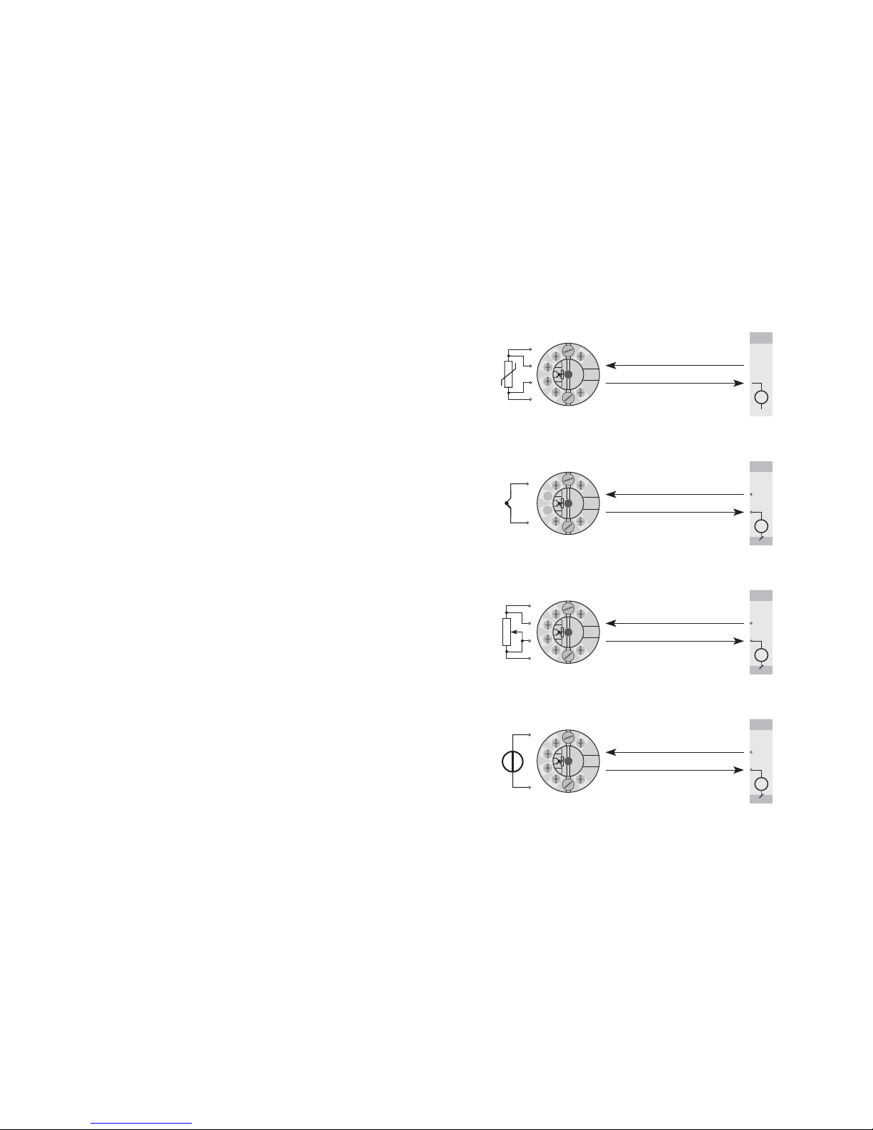
5
+
-
+
-
+
-
+
-
+
-
+
-
+
-
+
-
V+
mA
V+
mA
V+
mA
V+
mA
+
-
+
-
RTD til 4...20 mA
TC til 4...20 mA
Modstand til 4...20 mA
mV til 4...20 mA
2-trådsinstallation
i kontrolrum
2-trådsinstallation
i kontrolrum
2-trådsinstallation
i kontrolrum
2-trådsinstallation
i kontrolrum
2-TRÅDS PROGRAMMERBAR TRANSMITTER
PRetop 5331
• Indgang for RTD, TC, Ohm eller mV
• Ekstrem målenøjagtighed
• 1,5 kVAC galvanisk isolation
• Programmerbar følerfejlsværdi
• Kan monteres i DIN form B følerhoved
Anvendelse:
• Temperaturlineariseret måling med Pt100...Pt1000, Ni100...Ni1000 eller termoelementføler.
• Omsætning af lineær modstandsændring til standard analogt strømsignal,
f.eks. fra ventiler eller ohmske niveaustave.
• Forstærkning af bipolært mV-signal til et standard 4...20 mA strømsignal.
Teknisk karakteristik:
• PR5331 kan af brugeren i løbet af få sekunder programmeres til at måle inden
for alle normerede temperaturområder.
• RTD og modstandsindgangen har kabelkompensering for 2-, 3- og 4-leder
tilslutning.
• Der er løbende sikkerhedscheck af gemte data.
Montage / installation:
• Kan monteres i DIN form B følerhoved. I ikke-eksplosionsfarlige områder kan
5331 monteres på en DIN-skinne med PR-beslag type 8421.
• NB: Som Ex-barriere for 5331D anbefaler vi 5104B, 5114B eller 5116B.
4
Page 5
Virkning af forsyningsspændings-
ændring ....................................................... < 0,005% af span / VDC
Vibration ...................................................... IEC 60068-2-6 Test FC
Lloyd’s specifikation nr. 1 ............................ 4 g / 2...100 Hz
Max. ledningskvadrat .................................. 1 x 1,5 mm
2
flerkoret ledning
Klemskruetilspændingsmoment .................. 0,4 Nm
Luftfugtighed ............................................... < 95% RH (ikke kond.)
Mål ............................................................. Ø 44 x 20,2 mm
Kapslingsklasse (hus / klemme) .................. IP68 / IP00
Vægt ............................................................ 50 g
Elektriske specifikationer indgang:
RTD- og lineær modstandsindgang:
Max. nulpunktsforskydning (offset) ............. 50% af valgt max. værdi
Kabelmodstand pr. leder (max.) .................. 5 Ω
Følerstrøm ................................................... Nom. 0,2 mA
Virkning af følerkabelmodstand
(3- / 4-leder) ................................................ < 0,002 Ω/Ω
Følerfejlsdetektering .................................... Ja
7
Basisværdier
Temperatur-
koefficient
Basis
nøjagtighedIndgangstype
RTD
Lin.R
Volt
TC-type:
E, J, K, L, N, T, U
TC-type: B, R, S,
W3, W5, LR
≤ ±0,2°C
≤ ±0,1 Ω
≤ ±10 µV
≤ ±1°C
≤ ±2°C
≤ ±0,01°C/°C
≤ ±10 mΩ/°C
≤ ±1 µV/°C
≤ ±0,05°C/°C
≤ ±0,2°C/°C
EMC-immunitetspåvirkning ................................. < ±0,5% af span
Udvidet EMC-immunitet:
NAMUR NE 21, A kriterium, gniststøj ................. < ±1% af span
Elektriske specifikationer:
Specifikationsområde:
-40°C til +85°C
Fælles specifikationer:
Forsyningsspænding DC
Standard .............................................. 7,2...35 V
CSA, FM & CSA ................................... 7,2...30 VDC
Egetforbrug ................................................. 25 mW...0,8 W
Spændingsdrop ........................................... 7,2 VDC
Isolationsspænding, test / drift ................... 1,5 kVAC / 50 VAC
Opvarmningstid ........................................... 5 min.
Kommunikationsinterface ............................ Loop Link
Signal- / støjforhold ..................................... Min. 60 dB
Reaktionstid (programmerbar) .................... 1...60 s
EEprom fejlcheck ........................................ < 3,5 s
Signaldynamik, indgang .............................. 20 bit
Signaldynamik, udgang ............................... 16 bit
Kalibreringstemperatur ................................ 20...28°C
Nøjagtighed, størst af generelle og basisværdier:
6
5331
-40°C…+85°C : 3 1500 VAC : B
Omgivelses-
temperatur
Galvanisk
isolation
Type Version
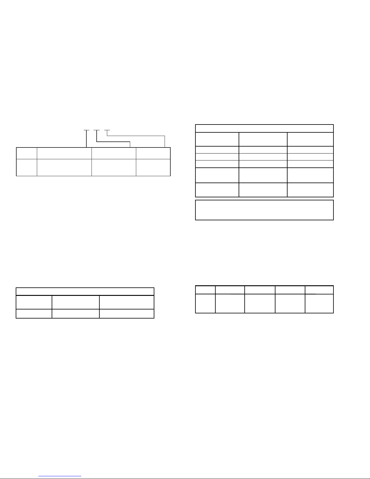
Bestillingsskema: 5331
Standard : A
CSA, FM & ATEX : D
Generelle værdier
Temperatur-
koefficient
Absolut
nøjagtighedIndgangstype
Alle
≤ ±0,05% af span
≤ ±0,01% af span / °C
Type Min. værdi Max. værdi Min. span Standard
Pt100 -200°C +850°C 25°C IEC 60751
Ni100 -60°C +250°C 25°C DIN 43760
Lin. R 0 Ω 5000 Ω 30 Ω −−−−−
Page 6

EEx- / I.S.-godkendelse - 5331D:
KEMA 06ATEX0062 X .................................. II 1 GD, T80°C...T105°C
EEx ia IIC T6 / T4
Max. omgivelsestemp. for T1...T4 .............. 85°C
Max. omgivelsestemp. for T5 og T6 .......... 60°C
ATEX, må anvendes i zone .......................... 0, 1, 2, 20, 21 eller 22
Ex- / I.S.-data:
Signaludgang / forsyning, terminal 1 til 2:
Ui ................................................................. : 30 VDC
Ii .................................................................. : 120 mADC
Pi ................................................................. : 0,84 W
Li ................................................................. : 10 µH
Ci ................................................................. : 1 nF
Følerindgang, terminal 3, 4, 5 og 6:
Uo ............................................................... : 9,6 VDC
I o ................................................................ : 25 mA
Po ................................................................ : 60 mW
L o ................................................................ : 33 mH
Co ............................................................... : 2,4 µF
FM, må anvendes i ...................................... IS, Class I, Div. 1, Group A, B, C, D
IS, Class I, Zone 0, AEx ia IIC
FM Installation Drawing No. ................ 5300Q502
CSA, må anvendes i .................................... IS, Class I, Div. 1, Group A, B, C, D,
IS, Class I, Zone 0, Ex ia IIC
CSA Installation Drawing No. .............. 533XQC03
Marine-godkendelse:
Det Norske Veritas, Ships & Offshore ......... Standard for Certification No. 2.4
GOST R godkendelse:
VNIIM & VNIIFTRI, Cert. no. ........................ Se www.prelectronics.dk
Overholdte myndighedskrav: Standard:
EMC 2004/108/EF ....................................... EN 61326-1
ATEX 94/9/EF .............................................. EN 50014, EN 50020, EN 50284,
IEC 61241-0 og IEC 61241-11
FM ............................................................... 3600, 3611, 3610
CSA, CAN / CSA ......................................... C22.2 No. 157, E60079-11, UL 913
Af span = Af det aktuelt valgte område
9
TC-indgang:
Max. nulpunktsforskydning (offset) ............. 50% af valgt max. værdi
Koldt loddestedskomp. (CJC) ..................... < ±1,0°C
Følerfejlsdetektering .................................... Ja
Følerfejlsstrøm:
under detektering ................................. Nom. 33 mA
ellers ..................................................... 0 mA
Spændingsindgang:
Måleområde ............................................... -12...800 mV
Min. måleområde (span) .............................. 5 mV
Max. nulpunktsforskydning (offset) ............. 50% af valgt max. værdi
Indgangsmodstand ..................................... 10 MΩ
Udgang:
Strømudgang:
Signalområde .............................................. 4...20 mA
Min. signalområde ....................................... 16 mA
Opdateringstid ............................................. 440 ms
Udgangssignal ved EEpromfejl ................... ≤ 3,5 mA
Belastningsmodstand .................................. ≤ (V
forsyn.
- 7,2) / 0,023 [Ω]
Belastningsstabilitet .......................................... < ±0,01% af span / 100 Ω
Følerfejlsdetektering:
Programmerbar ........................................... 3,5...23 mA
NAMUR NE43 Upscale ............................... 23 mA
NAMUR NE43 Downscale ........................... 3,5 mA
8
Type
Min.
temperatur
Max.
temperatur
Min.
span Standard
B
E
J
K
L
N
R
S
T
U
W3
W5
LR
+400°C
-100°C
-100°C
-180°C
-100°C
-180°C
-50°C
-50°C
-200°C
-200°C
0°C
0°C
-200°C
+1820°C
+1000°C
+1200°C
+1372°C
+900°C
+1300°C
+1760°C
+1760°C
+400°C
+600°C
+2300°C
+2300°C
+800°C
200°C
50°C
50°C
50°C
50°C
100°C
200°C
200°C
50°C
75°C
200°C
200°C
50°C
IEC584
IEC584
IEC584
IEC584
DIN 43710
IEC584
IEC584
IEC584
IEC584
DIN 43710
ASTM E988-90
ASTM E988-90
GOST 3044-84
Page 7
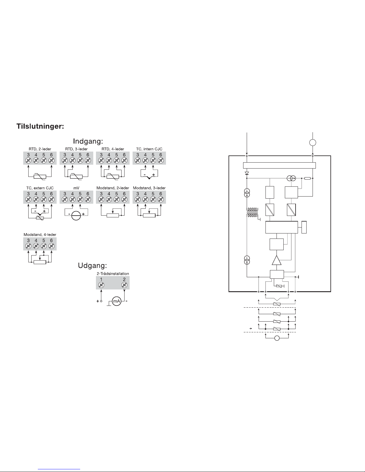
11
0...16
mA
4
3
2
1
5
6
4
3
2
+
-
+
-
mV
mA
MUX
4 mA
5331
PGA
D / A
Comu.
A / D
CPU
EEPROM
Indgang gnd.
BLOKDIAGRAM:
Forsyning -
4...20 mA
Forsyning +
7,2...35 VDC
TC
Ext.
CJC
mV
RTD, lin. R
- tråd
Ex-kredsløb, kun 5331D
Int.
CJC
10
Page 8
2-WIRE
PROGRAMMABLE TRANSMITTER
PRetop 5331
CONTENTS
Safety instructions .............................................................. 14
EC Declaration of Conformity ............................................ 15
Application ......................................................................... 16
Technical characteristics .................................................... 16
Mounting / installation ........................................................ 16
Applications ........................................................................ 17
Order .................................................................................. 18
Electrical specifications ...................................................... 18
Connections ....................................................................... 22
Block diagram .................................................................... 23
Programming ...................................................................... 24
Mechanical specifications .................................................. 24
Mounting of sensor wires ................................................... 24
Appendix:
FM Installation Drawing No. 5300Q502 ............................. 50
CSA Installation Drawing No. 533XQC03 .......................... 52
13
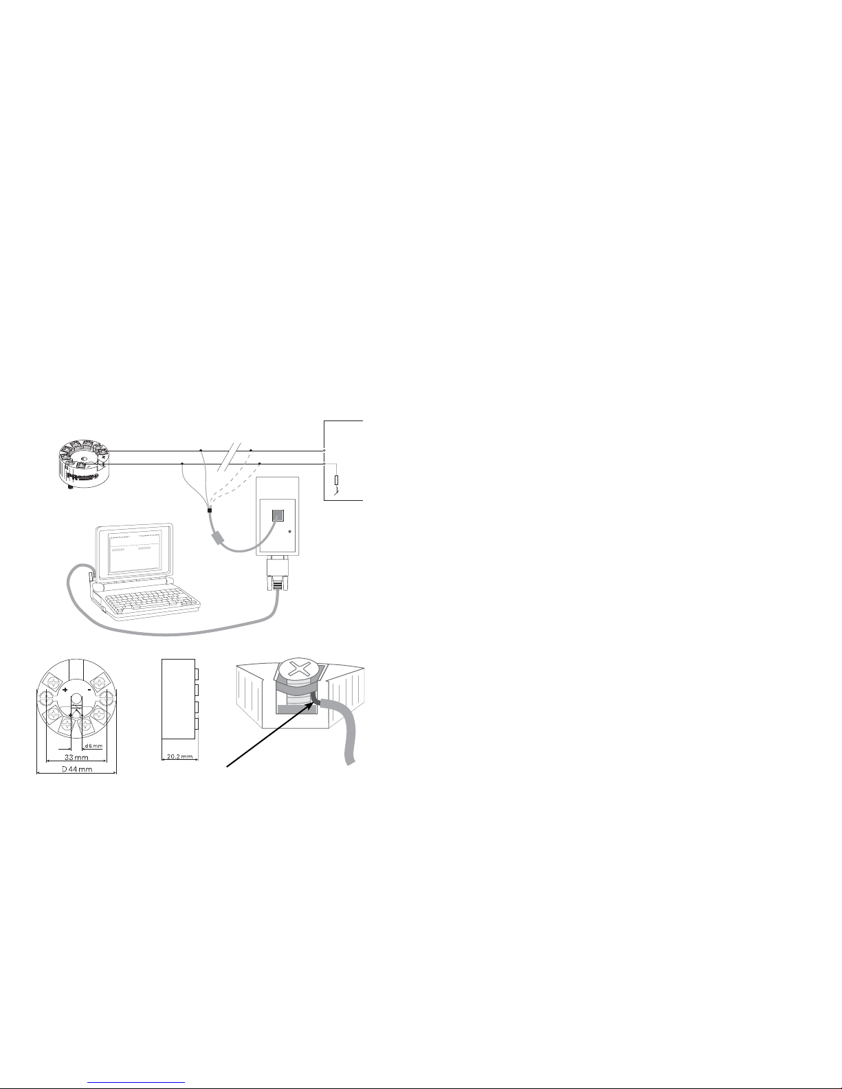
Programmering:
• Loop Link er et batteridrevet kommunikationsinterface, der er nødvendigt for
programmering af PRetop 5331.
• Ved programmering henvises til tegningen nedenfor og hjælpefunktionen i
PReset programmet.
• Loop Link må ikke benyttes til kommunikation med moduler installeret i Exområde
Bestilling: Loop Link
Mekaniske specifikationer: Montering af følerledninger:
12
PRetop 5331
1
2
F
i
l
e
P
r
o
d
u
c
t
I
n
p
u
t
O
u
t
p
u
t
C
o
m
m
u
n
i
c
a
t
i
o
n
L
a
n
g
u
a
g
e
O
p
t
i
o
n
0
8
:
3
0
:
0
0
P
R
e
t
o
p
5
3
3
1
D
a
t
e
:
1
9
9
4
-
8
-
1
0
9
4
3
2
0
1
5
9
4
P
R
e
l
e
c
t
r
o
n
i
c
s
A
n
a
l
o
g
i
n
p
u
t
A
n
a
l
o
g
o
u
t
p
u
t
S
e
r
i
a
l
n
o
:
I
n
p
u
t
t
y
p
e
:
O
u
t
p
u
t
t
y
p
e
:
4
-
2
0
m
A
U
p
s
c
a
l
e
S
e
n
s
o
r
e
r
r
o
r
:
P
t
1
0
0
D
I
N
/
I
E
C
0
.
0
0
-
5
0
.
0
0
C
3
-
w
i
r
e
1
.
0
0
s
e
c
-
-
-
-
-
-
I
n
p
u
t
r
a
n
g
e
:
C
o
n
n
e
c
t
i
o
n
:
C
o
l
d
j
u
n
c
t
i
o
n
c
o
m
p
:
R
e
s
p
o
n
s
e
t
i
m
e
:
T
a
g
n
o
:
*
*
COM
Loop Link
Afbryd
+Vforsyning
* Kun forbundet ved
on-line programmering
Sort
Rød
Gul
Grøn
Indgang
Modtagende
udstyr
Stikfor-
bindelse
Ledninger monteres mellem metalpladerne
Page 9

EC DECLARATION OF CONFORMITY
As manufacturer
PR electronics A/S
Lerbakken 10
DK-8410 Rønde
hereby declares that the following product:
Type: 5331
Name: 2-Wire programmable transmitter
is in conformity with the following directives and standards:
The EMC Directive 2004/108/EC and later amendments
EN 61326-1 : 2006
For specification of the acceptable EMC performance level, refer to the
electrical specifications for the module.
The ATEX Directive 94/9/EC and later amendments
EN 50014 : 1997 + A1, A2, EN 50020 : 2002 and
EN 50284 : 1999
IEC 61241-0 : 2004 and IEC 61241-11 : 2005
ATEX certificate: KEMA 06ATEX0062 X (5331D)
No changes are required to enable compliance with the replacement standards:
EN 60079-0 : 2006 and EN 60079-11 : 2007
Notified body
KEMA Quality B.V. (0344)
Utrechtseweg 310, 6812 AR Arnhem
P.O. Box 5185, 6802 ED Arnhem
The Netherlands
Rønde, 24 February 2009 Peter Rasmussen
Manufacturer’s signature
15
Safety instructions
Ex installation:
For a safe installation of 5331D in hazardous area the following must be
observed. The module must only be installed by qualified personnel who are
familiar with the national and international laws, directives and standards that
apply to this area.
Year of manufacture can be taken from the first two digits in the serial number.
The sensor circuit is not infallibly galvanically isolated from the input
circuit. However, the galvanic isolation between the circuits is capable of
withstanding a test voltage of 500 Vac during 1 minute.
The transmitter must be mounted in an enclosure in order to provide a degree
of ingress protection of at least IP20.
In explosive atmospheres caused by air / dust mixtures:
The transmitter may only be installed in a potentially explosive atmosphere
caused by the presence of combustible dust when mounted in a metal
enclosure form B according to DIN 43729 that is providing a degree of
ingress protection of at least IP 6X in accordance with EN 60529, that is
suitable for the application and is correctly installed.
Cable entries and blanking elements shall be used that are suitable for the
application and correctly installed.
For an ambient temperature ≥ 60°C, heat resistant cables shall be used with a
rating of at least 20 K above the ambient temperature.
Special conditions for safe use:
If the enclosure in which the transmitter is mounted is made of aluminium and
installed in Zone 0, 1 or Zone 20, 21 or 22 it shall not contain by weight more
than 6% in total of magnesium and titanium.
The additional enclosure of the apparatus shall be designed and/or installed in
such a way that, even in the event of rare incidents, ignition sources due to
impact and friction sparks are excluded.
14
Page 10
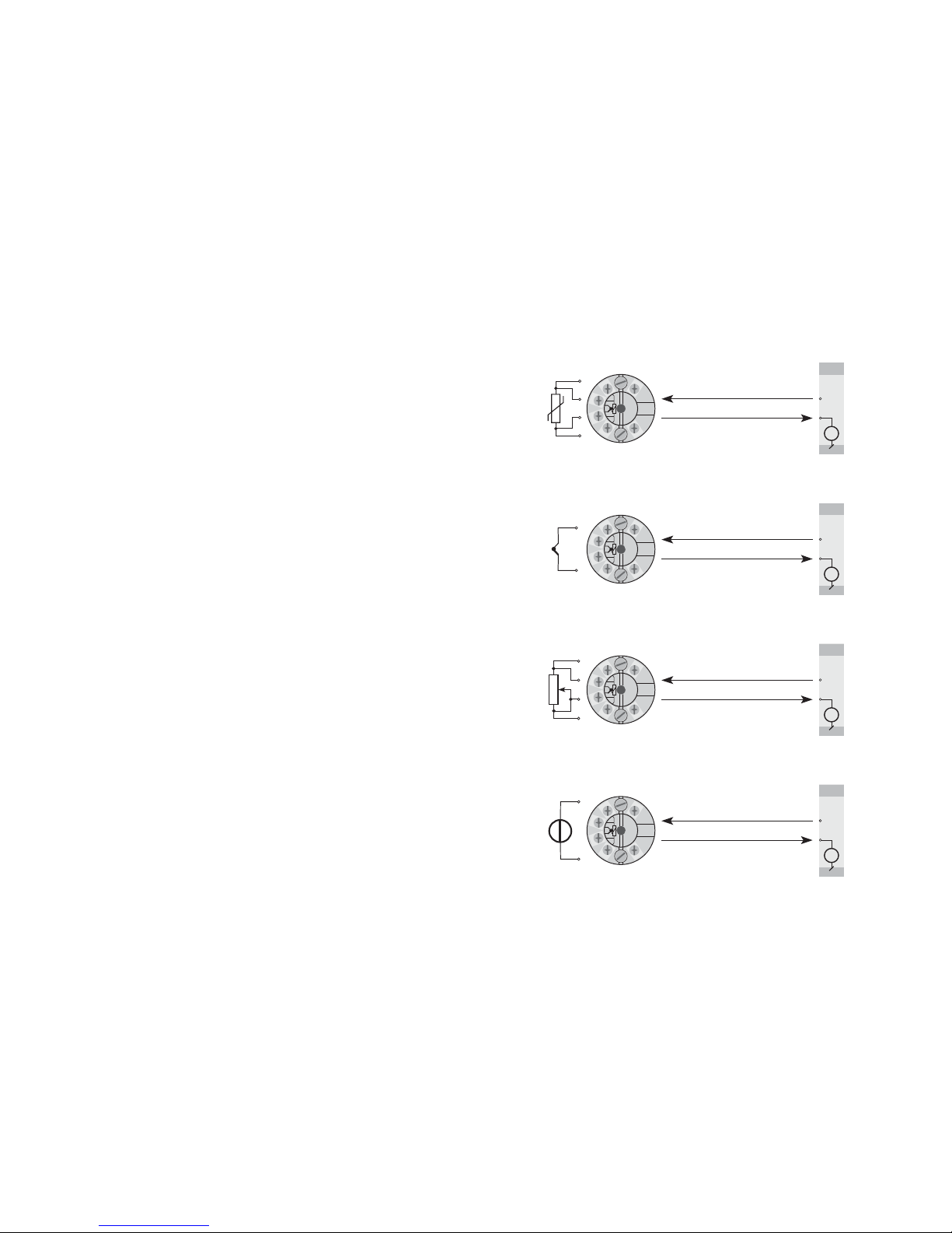
17
+
-
+
-
+
-
+
-
+
-
+
-
+
-
+
-
+
-
V+
mA
V+
mA
V+
mA
V+
mA
+
-
RTD to 4...20 mA
TC to 4...20 mA
Resistance to 4...20 mA
mV to 4...20 mA
2-wire installation
in control room
2-wire installation
in control room
2-wire installation
in control room
2-wire installation
in control room
2-WIRE PROGRAMMABLE TRANSMITTER
PRetop 5331
• RTD, TC, Ohm, or mV input
• Extremely high measurement accuracy
• 1.5 kVAC galvanic isolation
• Programmable sensor error value
• For DIN form B sensor head mounting
Application:
• Linearised temperature measurement with Pt100...Pt1000, Ni100...Ni1000, or
TC sensor.
• Conversion of linear resistance variation to a standard analogue current signal,
for instance from valves or Ohmic level sensors.
• Amplification of a bipolar mV signal to a standard 4...20 mA current signal.
Technical characteristics:
• Within a few seconds the user can program PR5331 to measure temperatures
within all ranges defined by the norms.
• The RTD and resistance inputs have cable compensation for 2-, 3- and 4-wire
connection.
• Continuous check of vital stored data for safety reasons.
Mounting / installation:
• For DIN form B sensor head mounting. In non-hazardous areas the 5331 can
be mounted on a DIN rail with the PR fitting type 8421.
• NB: As Ex barrier for 5331D we recommend 5401B, 5114B, or 5116B.
16
Page 11
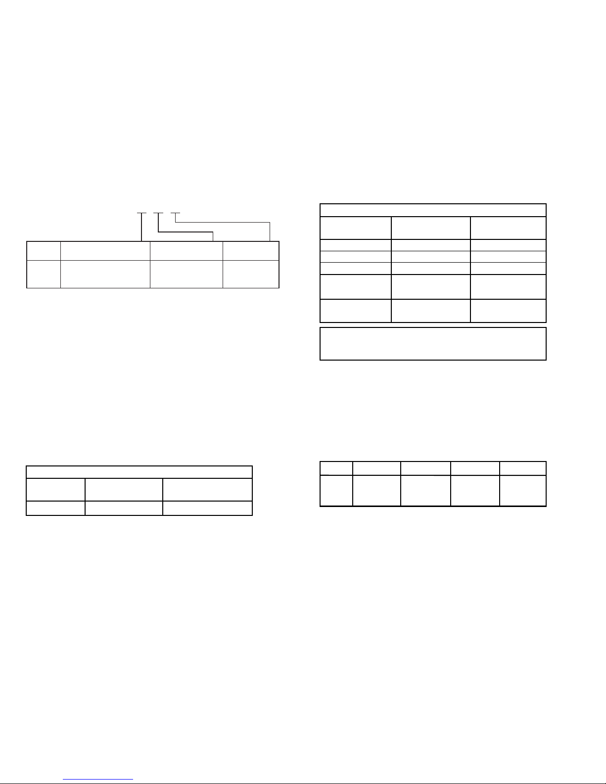
Effect of supply voltage variation ................ < 0.005% of span / VDC
Vibration ...................................................... IEC 60068-2-6 Test FC
Lloyd’s specification no. 1 .......................... 4 g / 2...100 Hz
Max. wire size .............................................. 1 x 1.5 mm
2
stranded wire
Screw terminal torque ................................. 0.4 Nm
Humidity ...................................................... < 95% RH (non-cond.)
Dimensions .................................................. Ø 44 x 20.2 mm
Protection degree (enclosure / terminal) ..... IP68 / IP00
Weight ......................................................... 50 g
Electrical specifications, input:
RTD and linear resistance input:
Max. offset .................................................. 50% of selec. max. value
Cable resistance per wire (max.) ................. 5 Ω
Sensor current ............................................. Nom. 0.2 mA
Effect of sensor cable resistance
(3- / 4-wire) .................................................. < 0.002 Ω/Ω
Sensor error detection ................................ Yes
19
Basic values
Temperature
coefficient
Basic
accuracyInput type
RTD
Lin. R
Volt
TC type:
E, J, K, L, N, T, U
TC type: B, R, S,
W3, W5, LR
≤ ±0.2°C
≤ ±0.1 Ω
≤ ±10 µV
≤ ±1°C
≤ ±2°C
≤ ±0.01°C/°C
≤ ±10 mΩ/°C
≤ ±1 µV/°C
≤ ±0.05°C/°C
≤ ±0.2°C/°C
EMC immunity influence ..................................... < ±0.5% of span
Extended EMC immunity:
NAMUR NE 21, A criterion, burst ....................... < ±1% of span
Electrical specifications:
Specifications range:
-40°C to +85°C
Common specifications:
Supply voltage, DC
Standard .............................................. 7.2...35 V
CSA, FM & ATEX .................................. 7.2...30 VDC
Internal consumption .................................. 25 mW...0.8 W
Voltage drop ................................................ 7.2 VDC
Isolation voltage, test / operation ............... 1.5 kVAC / 50 VAC
Warm-up time .............................................. 5 min.
Communications interface .......................... Loop Link
Signal / noise ratio ...................................... Min. 60 dB
Response time (programmable) .................. 1...60 s
EEprom error check .................................... < 3.5 s
Signal dynamics, input ................................ 20 bit
Signal dynamics, output ............................. 16 bit
Calibration temperature .............................. 20...28°C
Accuracy, the greater of general and basic values:
18
5331
-40°C…+85°C : 3 1500 VAC : B
Ambient
temperature
Galvanic
isolation
Type Version
Order: 5331
Standard : A
CSA, FM & ATEX : D
General values
Temperature
coefficient
Absolute
accuracyInput type
All
≤ ±0.05% of span
≤ ±0.01% of span / °C
Type Min. value Max. value Min. span Standard
Pt100 -200°C +850°C 25°C IEC 60751
Ni100 -60°C +250°C 25°C DIN 43760
Lin. R 0 Ω 5000 Ω 30 Ω −−−−−
Page 12

EEx / I.S. approval - 5331D:
KEMA 06ATEX0062 X .................................. II 1 GD, T80°C...T105°C
EEx ia IIC T6 / T4
Max. amb. temperature for T1...T4 ............. 85°C
Max. amb. temperature for T5 and T6 ....... 60°C
ATEX, applicable in zone ............................. 0, 1, 2, 20, 21 or 22
Ex / I.S. data:
Signal output / supply, terminal 1 to 2:
U
i
................................................................. : 30 VDC
I
i
................................................................... : 120 mADC
P
i
................................................................. : 0.84 W
L
i
.................................................................. : 10 µH
C
i
................................................................. : 1.0 nF
Sensor input, terminal 3, 4, 5 and 6:
U
o
.............................................................: 9.6 VDC
I
o
.............................................................: 25 mA
P
o
.............................................................: 60 mW
L
o
.............................................................: 33 mH
C
o
.............................................................: 2.4 µF
FM, applicable in ......................................... IS, Class I, Div. 1, Group A, B, C, D
IS, Class I, Zone 0, AEx ia IIC
FM Installation Drawing No. ................ 5300Q502
CSA, applicable in ....................................... IS, Class I, Div. 1, Group A, B, C, D,
IS, Class I, Zone 0, Ex ia IIC
CSA Installation Drawing No. .............. 533XQC03
Marine approval:
Det Norske Veritas, Ships & Offshore ......... Standard for Certification No. 2.4
GOST R approval:
VNIIM & VNIIFTRI, Cert. no. ........................ See www.prelectronics.com
Observed authority requirements: Standard:
EMC 2004/108/EC ...................................... EN 61326-1
ATEX 94/9/EC .............................................. EN 50014, EN 50020, EN 50284,
IEC 61241-0 and IEC 61241-11
FM ............................................................... 3600, 3611, 3610
CSA, CAN / CSA ......................................... C22.2 No. 157, E60079-11, UL 913
Of span = Of the presently selected range
21
TC input:
Max. offset .................................................. 50% of selec. max. value
Cold junction compensation ....................... < ±1.0°C
Sensor error detection ................................ Yes
Sensor error current:
When detecting .................................... Nom. 33 mA
Else ...................................................... 0 mA
Voltage input:
Measurement range .................................... -12...800 mV
Min. span ..................................................... 5 mV
Max. offset .................................................. 50% of selec. max. value
Input resistance ........................................... 10 MΩ
Output:
Current output:
Signal range ................................................ 4...20 mA
Min. signal range ......................................... 16 mA
Updating time .............................................. 440 ms
Output signal at EEprom error .................... ≤ 3.5 mA
Load resistance ........................................... ≤ (V
supply
- 7.2) / 0.023 [Ω]
Load stability ............................................... < ±0.01% of span / 100 Ω
Sensor error detection:
Programmable ............................................. 3.5...23 mA
Namur NE43 Upscale .................................. 23 mA
Namur NE43 Downscale ............................. 3.5 mA
20
Type
Min.
temperature
Max.
temperature
Min.
span Standard
B
E
J
K
L
N
R
S
T
U
W3
W5
LR
+400°C
-100°C
-100°C
-180°C
-100°C
-180°C
-50°C
-50°C
-200°C
-200°C
0°C
0°C
-200°C
+1820°C
+1000°C
+1200°C
+1372°C
+900°C
+1300°C
+1760°C
+1760°C
+400°C
+600°C
+2300°C
+2300°C
+800°C
200°C
50°C
50°C
50°C
50°C
100°C
200°C
200°C
50°C
75°C
200°C
200°C
50°C
IEC584
IEC584
IEC584
IEC584
DIN 43710
IEC584
IEC584
IEC584
IEC584
DIN 43710
ASTM E988-90
ASTM E988-90
GOST 3044-84
Page 13
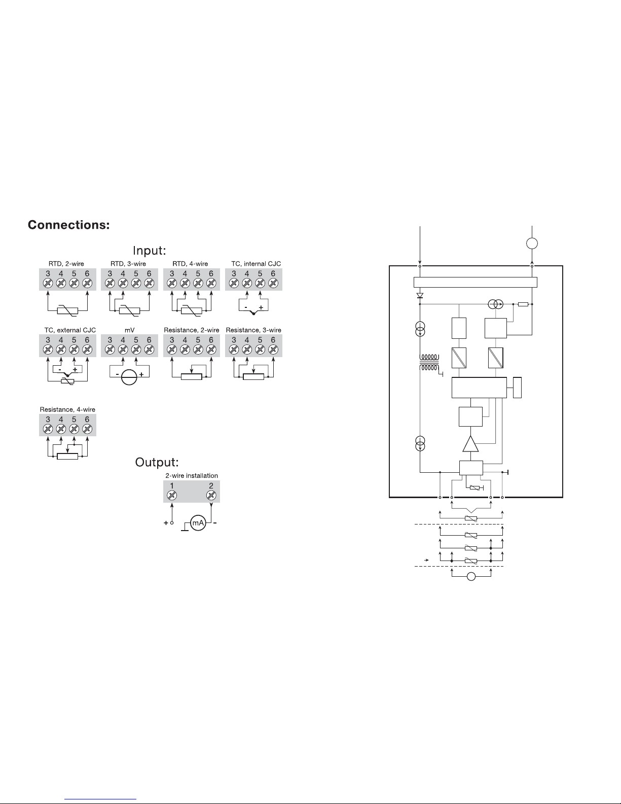
23
0...16
mA
4
3
2
1
5
6
4
3
2
+
-
+
-
mV
mA
MUX
4 mA
5331
PGA
D / A
Comu.
A / D
CPU
EEPROM
BLOCK DIAGRAM:
Input gnd.
Supply -
4...20 mA
TC
Ext.
CJC
mV
RTD, lin. R
- wire
Int.
CJC
Ex circuit, only 5331D
Supply +
7.2...35 VDC
22
Page 14
TRANSMETTEUR 2-FILS
UNIVERSEL (Pt100/TC)
PRetop 5331
SOMMAIRE
Consigne de sécurité ......................................................... 26
Déclaration de conformité CE ............................................ 27
Application ......................................................................... 28
Caractéristiques techniques .............................................. 28
Montage / installation ......................................................... 28
Applications ........................................................................ 29
Référence ........................................................................... 30
Spécifications électriques .................................................. 30
Connexions ........................................................................ 34
Schéma de principe ........................................................... 35
Programmation ................................................................... 36
Dimensions mécaniques .................................................... 36
Montage des fils du capteur .............................................. 36
Appendix:
FM Installation Drawing No. 5300Q502 ............................. 50
CSA Installation Drawing No. 533XQC03 .......................... 52
25
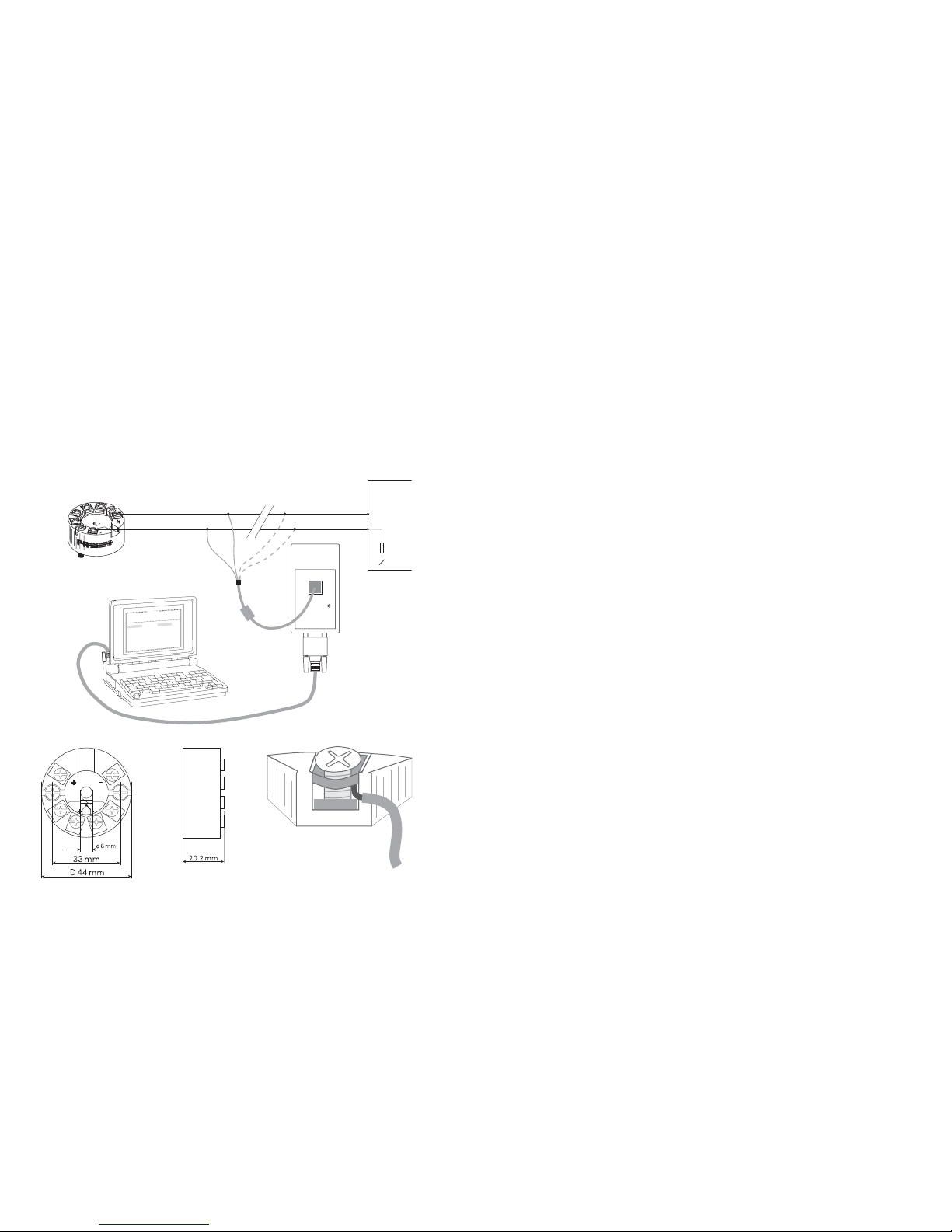
Programming:
• Loop Link is a communications interface that is needed for programming
PRetop 5331.
• For programming please refer to the drawing below and the help functions in
PReset.
• Loop link is not approved for communication with modules installed in
harzard ous (Ex) areas
Order: Loop Link
Mechanical specifications: Mounting of sensor wires
24
PRetop 5331
1
2
F
i
l
e
P
r
o
d
u
c
t
I
n
p
u
t
O
u
t
p
u
t
C
o
m
m
u
n
i
c
a
t
i
o
n
L
a
n
g
u
a
g
e
O
p
t
i
o
n
0
8
:
3
0
:
0
0
P
R
e
t
o
p
5
3
3
1
D
a
t
e
:
1
9
9
4
-
8
-
1
0
9
4
3
2
0
1
5
9
4
P
R
e
l
e
c
t
r
o
n
i
c
s
A
n
a
l
o
g
i
n
p
u
t
A
n
a
l
o
g
o
u
t
p
u
t
S
e
r
i
a
l
n
o
:
I
n
p
u
t
t
y
p
e
:
O
u
t
p
u
t
t
y
p
e
:
4
-
2
0
m
A
U
p
s
c
a
l
e
S
e
n
s
o
r
e
r
r
o
r
:
P
t
1
0
0
D
I
N
/
I
E
C
0
.
0
0
-
5
0
.
0
0
C
3
-
w
i
r
e
1
.
0
0
s
e
c
-
-
-
-
-
-
I
n
p
u
t
r
a
n
g
e
:
C
o
n
n
e
c
t
i
o
n
:
C
o
l
d
j
u
n
c
t
i
o
n
c
o
m
p
:
R
e
s
p
o
n
s
e
t
i
m
e
:
T
a
g
n
o
:
*
*
COM
Loop Link
Disconnect
+Vsupply
* Connected only for
on-line programming
Black
Red
Yellow
Green
Input
Receiving
Equipment
Connector
Wires must be mounted between the metal
plates.
Page 15

DECLARATION DE CONFORMITE CE
En tant que fabricant
PR electronics A/S
Lerbakken 10
DK-8410 Rønde
déclare que le produit suivant :
Type : 5331
Nom : Transmetteur 2-fils universel
correspond aux directives et normes suivantes :
La directive CEM (EMC) 2004/108/CE et les modifications subséquentes
EN 61326-1 : 2006
Pour une spécification du niveau de rendement acceptable CEM (EMC)
renvoyer aux spécifications électriques du module.
La directive ATEX 94/9/EC et les modifications subséquentes
EN 50014 : 1997 + A1, A2, EN 50020 : 2002 et
EN 50284 : 1999
IEC 61241-0 : 2004 et IEC 61241-11 : 2005
Certificat ATEX : KEMA 06ATEX0062 X (5331D)
Aucune modification n’est exigée pour permettre la conformité aux normes de
remplacement :
EN 60079-0 : 2006 et EN 60079-11 : 2007
Organisme notifié
KEMA Quality B.V. (0344)
Utrechtseweg 310, 6812 AR Arnhem
P.O. Box 5185, 6802 ED Arnhem
The Netherlands
Rønde, le 24 février 2009 Peter Rasmussen
Signature du fabricant
27
Consigne de sécurité
Installation S.I. :
Pour l’installation de 5331D dans les zones dangereuses, conformez-vous aux
consignes de sécurité suivantes : l’installation ne doit être réalisée
que par du personnel qualifié connaissant la législation nationale et
internationale ainsi que les directives et standards régissant ce domaine.
L’année de production ressort des deux premiers chiffres du numéro de série.
L’isolation galvanique entre le circuit du capteur et le circuit d’entrée n’est pas
infaillible. Cependant, l’isolation galvanique entre les circuits est capable de
résister à une tension de test de 500 Vca pendant 1 minute.
Le transmetteur doit être monté dans un boîtier assurant un degré d’étanchéité
d’au moins IP20.
Dans les atmosphères explosibles dues à des mélanges d’air avec des poussières :
Le transmetteur doit seulement être installé dans les atmosphères potentiellement
explosibles dû à la présence de poussières combustibles quand il est monté
dans un boîtier métallique DIN B conformément à DIN 43729 assurant un
degré d’étanchéité d’au moins IP 6X conformément à l’EN 60529. Ce boîtier
doit convenir à l’application et il doit être correctement installé.
Seulement des raccords de câble et des bouchons convenant à l’application et
correctement installés doivent être utilisés.
Pour une température ambiante ≥60°C, il faut utiliser des câbles résistant aux
températures élevées avec une capacité nominale d’au moins 20 K au dessus
de la température ambiante.
Conditions spécifiques à l’utilisation sûre :
Si le boîtier dans lequel est monté le transmetteur est fait d’aluminium et installé
en zone 0, 1 ou zone 20, 21 ou 22, il ne doit contenir en poids plus que 6%
en total de magnésium et de titane.
Le boîtier supplémentaire de l’apparail doit être construit et/ou installé dans
une telle manière que, même dans le cas d’incidents rares, les sources
d’inflammation dûes aux impacts et aux étincelles de friction ne peuvent se
produire.
26
Page 16
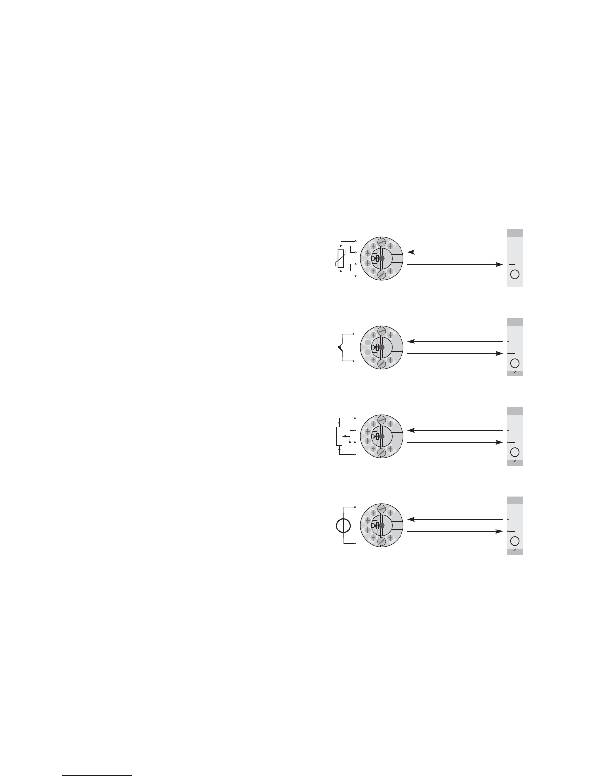
29
+
-
+
-
+
-
+
-
+
-
+
-
+
-
+
-
V+
mA
V+
mA
V+
mA
V+
mA
+
-
+
-
Installation 2-fils
en salle de contrôle
Installation 2-fils
en salle de contrôle
Installation 2-fils
en salle de contrôle
RTD en 4...20 mA
mV en 4...20 mA
Résistance
4...20 mA
TC en 4...20 mA
Installation 2-fils
en salle de contrôle
TRANSMETTEUR 2-FILS
UNIVERSEL (Pt100/TC)
PRetop 5331
• Entrée RTD, TC, Ohm ou mV
• Trés grande précision de mesure
• Isolation galvanique de 1,5 kVAC
• Sécurité programmable
• Pour tête de sonde DIN B
Application :
• Mesure linéarisée de la température avec un capteur Pt100...Pt1000, Ni100...
Ni1000 ou de thermocouples.
• Conversion d’une résistance linéaire en un signal courant standard
analogique pour mesurer par exemple le niveau ou la position d’une vanne.
• Amplification d’un signal mV bipolaire en un signal courant standard de 4...20
mA.
Caractéristiques techniques :
• Le PR5331 peut être programmé de manière simple et rapide.
• Compensation de ligne pour des entrées RTD et résistance avec un
raccordement à 2, 3 et 4 fils.
• Vérification continue des données sauvegardées.
Montage / installation :
• Pour tête de sonde DIN B. En zone non-dangereuse le 5331 peut être monté
sur rail DIN avec le support PR type 8421.
• N.B. : Comme barrière S.I. pour le 5331D nous recommandons le PR5104B,
5114B ou 5116B.
28
Page 17
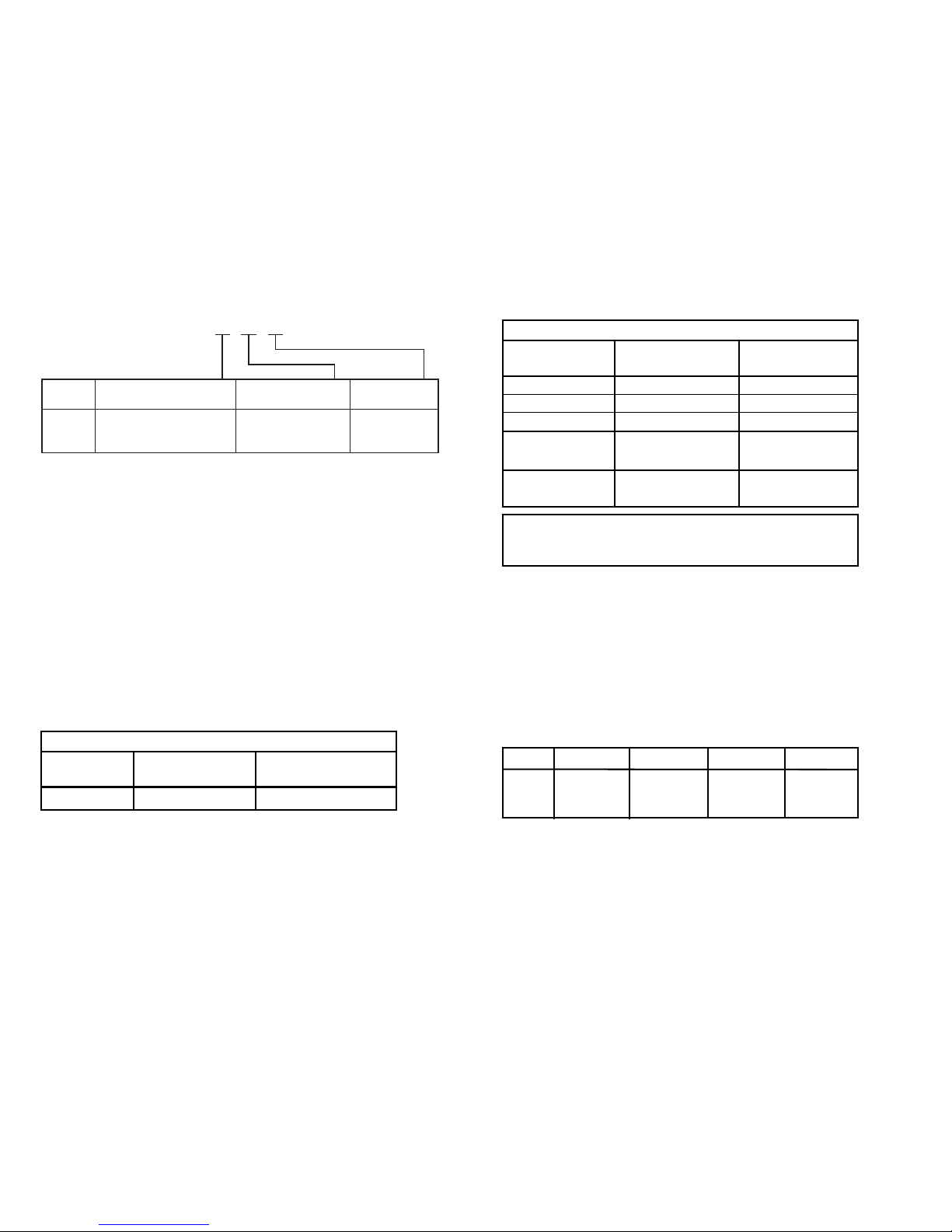
Effet d’une variation de
la tension d’alimentation ............................. < 0,005% de l’EC / Vcc
Vibration ...................................................... IEC 60068-2-6 Test FC
Lloyd, spécification no 1 ............................. 4 g / 2...100 Hz
Taille max. des fils ....................................... 1 x 1,5 mm
2
fil multibrins
Pression max. avant
déformation de la vis ................................... 0,4 Nm
Humidité ...................................................... < 95% HR (sans cond.)
Dimensions .................................................. Ø 44 x 20,2 mm
Degré de protection (boitier / bornier) ........ IP68 / IP00
Poids ........................................................... 50 g
Spécifications électriques, entrée :
Entrée RTD et entrée résistance linéaire :
Décalage max. ............................................ 50% de la valeur max. sélec.
Résistance de ligne max. par fils ................ 5 Ω
Courant de sonde ....................................... Nom. 0,2 mA
Effet de la résistance de ligne (3 / 4 fils) ..... < 0,002 Ω/Ω
Détection de rupture sonde ........................ Oui
31
Valeurs de base
Coefficient
de température
Précision
de base
Type
d’entrée
RTD
R. lin.
Volt
Type TC :
E, J, K, L, N, T, U
Type TC : B, R, S,
W3, W5, LR
≤ ±0,2°C
≤ ±0,1 Ω
≤ ±10 µV
≤ ±1°C
≤ ±2°C
≤ ±0,01°C/°C
≤ ±10 mΩ/°C
≤ ±1 µV/°C
≤ ±0,05°C/°C
≤ ±0,2°C/°C
Immunité CEM ..................................................... < ±0,5% de l’EC
Immunité CEM améliorée
:
NAMUR NE 21, critère A, burst ......................... < ±1% de l’EC
Spécifications électriques :
Plage des spécifications :
-40°C à +85°C
Spécifications communes :
Tension d’alimentation, cc
Standard .............................................. 7,2...35 V
CSA, FM & ATEX .................................. 7,2...30 Vcc
Consommation interne ................................ 25 mW...0,8 W
Chute de tension ......................................... 7,2 Vcc
Tension d’isolation, test / opération ............ 1,5 kVca / 50 Vca
Temps de chauffe ........................................ 5 min.
Kit de programmation ................................. Loop Link
Rapport signal / bruit .................................. Min. 60 dB
Temps de réponse (programmable) ............ 1...60 s
Vérification de l’EEprom .............................. < 3,5 s
Dynamique du signal d’entrée .................... 20 bit
Dynamique du signal de sortie ................... 16 bit
Température d’étalonnage .......................... 20...28°C
Précision, la plus grande des valeurs générales et de base :
30
5331
-40°C…+85°C : 3 1500 Vca : B
Température
ambiante
Isolation
galvanique
Type Version
Référence : 5331
Standard : A
CSA, FM & ATEX : D
Valeurs générales
Coefficient
de température
Précision
absolue
Type
d’entrée
Tous
≤ ±0,05% de l’EC
≤ ±0,01% de l’EC / °C
Type Valeur min. Valeur max. Plage min. Standard
Pt100 -200°C +850°C 25°C IEC 60751
Ni100 -60°C +250°C 25°C DIN 43760
R lin. 0 Ω 5000 Ω 30 Ω −−−−−
Page 18

Approbation EEx / S.I. - 5331D :
KEMA 06ATEX0062 X ................................. II 1 GD, T80°C...T105°C
EEx ia IIC T6 / T4
Température amb. max. (T1...T4) ................ 85°C
Température amb. max. (T5 et T6) .............. 60°C
ATEX, applicable en zone ............................ 0, 1, 2, 20, 21 ou 22
Caractéristiques S.I. :
Sortie signal / alimentation, borne 1 à 2 :
Ui ................................................................. : 30 Vcc
Ii .................................................................. : 120 mAcc
Pi ................................................................. : 0,84 W
Li ................................................................. : 10 µH
Ci ................................................................. : 1 nF
Entrée capteur, borne 3, 4, 5 et 6 :
Uo ............................................................... : 9,6 Vcc
Io ................................................................. : 25 mA
Po ................................................................ : 60 mW
Lo ................................................................ : 33 mH
Co ................................................................ : 2,4 µF
FM, applicable en ........................................ IS, Class I, Div. 1, Group A, B, C, D
IS, Class I, Zone 0, AEx ia IIC
FM Installation Drawing No. ................ 5300Q502
CSA, applicable en ...................................... IS, Class I, Div. 1, Group A, B, C, D,
IS, Class I, Zone 0, Ex ia IIC
CSA Installation Drawing No. .............. 533XQC03
Approbation marine :
Det Norske Veritas, Ships & Offshore ......... Standard for Certification No. 2.4
Approbation GOST R :
VNIIM & VNIIFTRI, Cert. no. ........................ Voir www.prelectronics.fr
Agréments et homologations : Standard :
CEM (EMC) 2004/108/CE ........................... EN 61326-1
ATEX 94/9/CE .............................................. EN 50014, EN 50020, EN 50284,
IEC 61241-0 et IEC 61241-11
FM ............................................................... 3600, 3611, 3610
CSA, CAN / CSA ......................................... C22.2 No. 157, E60079-11, UL 913
EC = Echelle configurée
33
Entrée TC :
Décalage max. ............................................ 50% de la valeur max. sélec.
Compensation de soudure froide ............... < ±1,0°C
Détection de rupture de sonde ................... Oui
Courant de sonde :
Pendant la détection ............................ Nom. 33 mA
Si non ................................................... 0 mA
Entrée tension :
Gamme de mesure ...................................... -12...800 mV
Plage de mesure min. ................................. 5 mV
Décalage max. ............................................ 50% de la valeur max. sélec.
Résistance d’entrée .................................... 10 MΩ
Sortie :
Sortie courant :
Gamme de mesure ...................................... 4...20 mA
Plage de mesure min. ................................. 16 mA
Temps de scrutation .................................... 440 ms
Sortie en cas de corruption de l’EEprom .... ≤ 3,5 mA
Résistance de charge .................................. ≤ (V
alim.
- 7,2) / 0,023 [Ω]
Stabilité de charge ............................................ < ±0,01% de l’EC / 100 Ω
Détection de rupture de sonde :
Programmable ............................................. 3,5...23 mA
NAMUR NE43 Haut d’échelle ..................... 23 mA
NAMUR NE43 Bas d’échelle ....................... 3,5 mA
32
Type
Température
min.
Température
max.
Plage
min. Standard
B
E
J
K
L
N
R
S
T
U
W3
W5
LR
+400°C
-100°C
-100°C
-180°C
-100°C
-180°C
-50°C
-50°C
-200°C
-200°C
0°C
0°C
-200°C
+1820°C
+1000°C
+1200°C
+1372°C
+900°C
+1300°C
+1760°C
+1760°C
+400°C
+600°C
+2300°C
+2300°C
+800°C
200°C
50°C
50°C
50°C
50°C
100°C
200°C
200°C
50°C
75°C
200°C
200°C
50°C
IEC584
IEC584
IEC584
IEC584
DIN 43710
IEC584
IEC584
IEC584
IEC584
DIN 43710
ASTM E988-90
ASTM E988-90
GOST 3044-84
Page 19
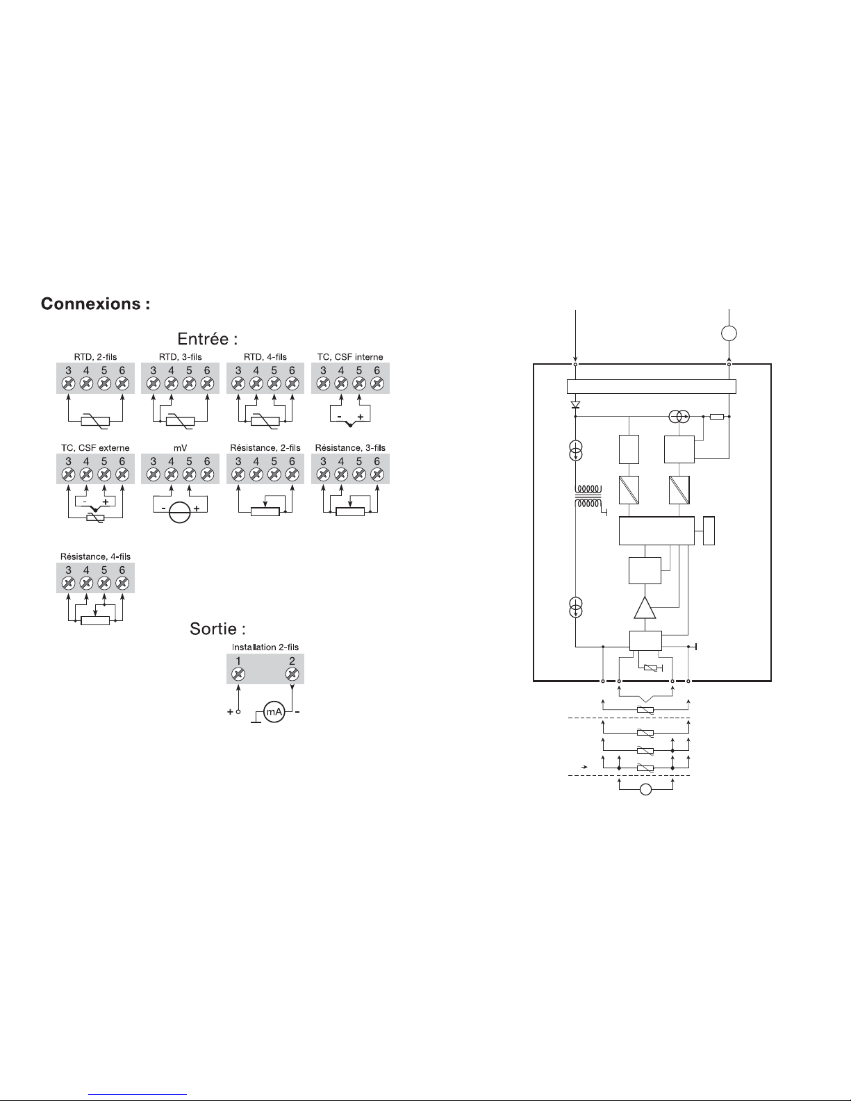
35
0...16
mA
4
3
2
1
5
6
4
3
2
+
-
+
-
mV
mA
MUX
4 mA
5331
PGA
D / A
Comu.
A / D
CPU
EEPROM
SCHEMA DE PRINCIPE :
Entrée masse
Alimentation -
4...20 mA
TC
CSF
ext.
mV
RTD, R. lin.
- fils
CSF
int.
Circuit S.I., seulement 5331D
Alimentation +
7,2...35 Vcc
34
Page 20
2-DRAHT
UNIVERSALMESSUMFORMER
PRetop 5331
Inhaltsverzeichnis
Sicherheitsinstruktion ......................................................... 38
EG-Konformitätserklärung .................................................. 39
Verwendung ........................................................................ 40
Technische Merkmale ......................................................... 40
Montage / installation ......................................................... 40
Anwendungen .................................................................... 41
Bestellangaben ................................................................... 42
Elektrische Daten ............................................................... 42
Anschlüsse ......................................................................... 46
Blockdiagramm .................................................................. 47
Programmierung ................................................................. 48
Abmessungen .................................................................... 48
Montage von Fühlerleitungen ............................................. 48
Appendix:
FM Installation Drawing No. 5300Q502 ............................. 50
CSA Installation Drawing No. 533XQC03 .......................... 52
37
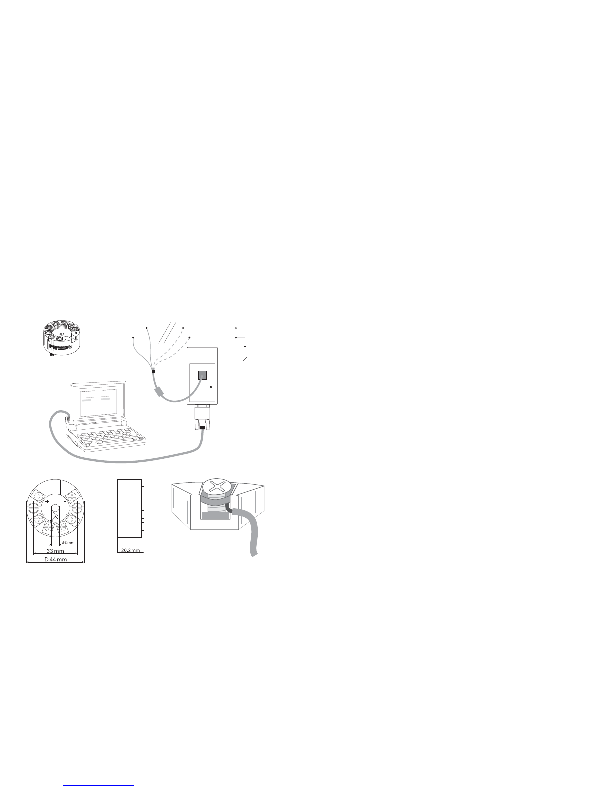
Programmation :
• Loop Link est un kit de programmation permettant de programmer le PRetop
5331.
• Pour le raccordement du Loop Link, veuillez vous reporter au schéma cidessous et à l’aide en ligne du logiciel PReset.
• Loop Link ne doit pas être utilisé pour communication avec des modules
installés en zone dangereuse.
Numéro de référence : Loop Link
Dimensions mécaniques : Montage des fils du capteur
36
PRetop 5331
1
2
F
i
l
e
P
r
o
d
u
c
t
I
n
p
u
t
O
u
t
p
u
t
C
o
m
m
u
n
i
c
a
t
i
o
n
L
a
n
g
u
a
g
e
O
p
t
i
o
n
0
8
:
3
0
:
0
0
P
R
e
t
o
p
5
3
3
1
D
a
t
e
:
1
9
9
4
-
8
-
1
0
9
4
3
2
0
1
5
9
4
P
R
e
l
e
c
t
r
o
n
i
c
s
A
n
a
l
o
g
i
n
p
u
t
A
n
a
l
o
g
o
u
t
p
u
t
S
e
r
i
a
l
n
o
:
I
n
p
u
t
t
y
p
e
:
O
u
t
p
u
t
t
y
p
e
:
4
-
2
0
m
A
U
p
s
c
a
l
e
S
e
n
s
o
r
e
r
r
o
r
:
P
t
1
0
0
D
I
N
/
I
E
C
0
.
0
0
-
5
0
.
0
0
C
3
-
w
i
r
e
1
.
0
0
s
e
c
-
-
-
-
-
-
I
n
p
u
t
r
a
n
g
e
:
C
o
n
n
e
c
t
i
o
n
:
C
o
l
d
j
u
n
c
t
i
o
n
c
o
m
p
:
R
e
s
p
o
n
s
e
t
i
m
e
:
T
a
g
n
o
:
*
*
COM
Loop Link
Débranché
+Valim.
* Connexion facultative
Noir
Rouge
Jaune
Vert e
Entrée
API ou autres
Connecteur
Les fils doivent être montés entre les
plaques métalliques.
Page 21

EG-KONFORMITÄTSERKLÄRUNG
Als Hersteller bescheinigt
PR electronics A/S
Lerbakken 10
DK-8410 Rønde
hiermit für das folgende Produkt:
Typ: 5331
Name: 2-Draht Universal Messumformer
die Konformität mit folgenden Richtlinien und Normen:
Die EMV Richtlinien 2004/108/EG und nachfolgende Änderungen
EN 61326-1 : 2006
Zur Spezifikation des zulässigen Erfüllungsgrades, siehe die Elektrische
Daten des Moduls.
Die ATEX Richtlinien 94/9/EC und nachfolgende Änderungen
EN 50014 : 1997 + A1, A2, EN 50020 : 2002 und
EN 50284 : 1999
IEC 61241-0 : 2004 und IEC 61241-11 : 2005
ATEX-Zertifikat: KEMA 06ATEX0062 X (5331D)
Änderungen zur Einhaltung der folgenden Nachfolgenormen sind nicht erforderlich.
EN 60079-0 : 2006 und EN 60079-11 : 2007
Zulassungsstelle
KEMA Quality B.V. (0344)
Utrechtseweg 310, 6812 AR Arnhem
P.O. Box 5185, 6802 ED Arnhem
The Netherlands
Rønde, 24. Februar 2009 Peter Rasmussen
Unterschrift des Herstellers
39
Sicherheitsinstruktion
Ex-Installation:
Für sichere Installation von 5331D in explosionsgefährdeter Umgebung muss
folgendes beobachtet werden. Die Installation muss nur von qualifizierten
Personen, die mit den nationalen und internationalen Gesetze, Direktiven und
Standards des Gebiets bekannt sind, vorgenommen werden.
Die ersten beiden Ziffern der Seriennummer geben das Produktionsjahr an.
Die galvnische Trennung zwischen dem Sensorkreis und dem Eingangskreis ist
nicht unfehlbar. Allerdings ist die galvanische Trennung zwischen den Kreisen
so ausgelegt, dass diese eine Testspannung von 500 Vac für eine Minute
aushält.
Der Messumformer muss in einem Gehäuse montiert werden, um die
Mindestanforderung des Berührungsschutzes mit dem Schutzgrad IP 20 zu
erreichen.
In Explosionsfähige Atmosphären durch Staub/Luft-Gemische:
Der Messumformer darf nur in einer potentiellen explosiven Atmosphäre,
basierend auf entflammbaren Staub, eingesetzt werden, wenn er in einem
Metallkopf Form B gemäß DIN 43729 montiert ist, welcher einen Schutzgrad
von mindestens IP 6X gemäß EN 60529 besitzt und für den dementsprechenden Einsatz zugelassen ist.
Es dürfen nur Kabeleinführungen und Abdeckungen eingesetzt werden, welche
für die jeweilige Anwendung zugelassen sind.
Bei einer Umgebungstemperatur ≥60°C müssen hitzebeständige
Leitungen eingesetzt werden, welche für eine mindestens 20 K höhere
Umgebungstemperatur zugelassen sind.
Sonderbedingungen für sichere Anwendung:
Wenn das Gehäuse, in dem der Messumformer montiert ist, aus Aluminium
gemacht ist und es in Zone 0, 1 oder Zone 20, 21 oder 22 installiert ist, es
muss höchstens eine Totale von 6% Magnesium und Titanium einhalten.
Das zusätzliche Gehäuse des Apparats ist so zu konstruieren und herzustellen,
dass Zündquellen (Stöße und Reibungsfunken) selbst bei selten auftretenden
Störungen vermieden werden.
38
Page 22
41
+
-
+
-
+
-
+
-
+
-
+
-
+
-
+
-
V+
mA
V+
mA
V+
mA
V+
mA
+
-
+
-
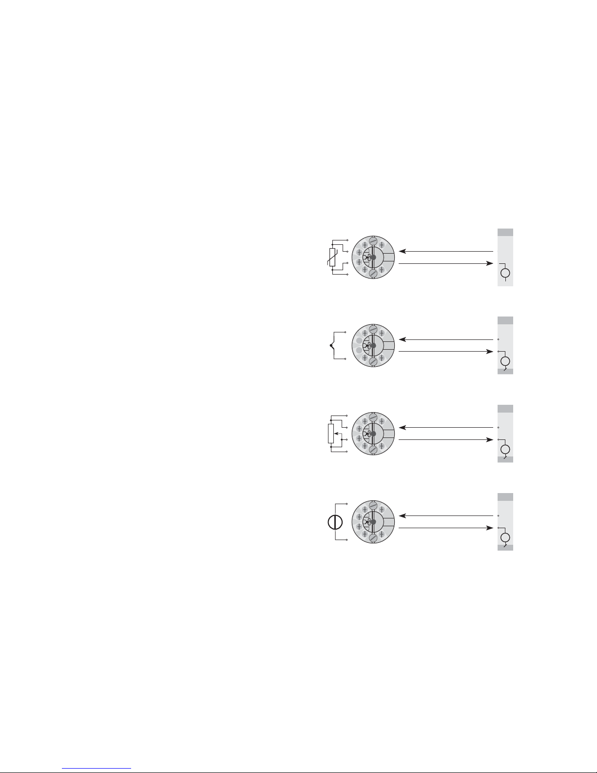
TE in 4...20 mA
Widerstand
in 4...20 mA
WTH in 4...20 mA
mV in 4...20 mA
2-Draht-Installation
im Kontrollraum
2-Draht-Installation
im Kontrollraum
2-Draht-Installation
im Kontrollraum
2-Draht-Installation
im Kontrollraum
40
2-DRAHT UNIVERSALMESSUMFORMER
PRetop 5331
• Eingang für WTH, TE, Ω oder mV
• Extreme Messgenauigkeit
• 1,5 kVAC mit galvanische Trennung
• Programmierbare Sensorfehlanzeige
• Für Einbau in Anschlusskopf DIN Form B
Verwendung:
• Linearisierte Temperaturmessung mit Pt100...Pt1000, Ni100...Ni1000 oder
Thermoelementsensor.
• Umwandlung von linearer Widerstandsänderung in ein analoges StandardStromsignal, z.B. von Ventilen oder Niveau-Messwertgeber.
• Verstärkung von bipolaren mV-Signalen zu einem Standard 4...20 mA
Stromsignal.
Technische Merkmale:
• PR5331 kann vom Benutzer innerhalb von wenigen Sekunden zur Messung in
allen genormten Temperaturbereiche programmiert werden.
• Der WTH- und Widerstandseingang haben Lei tungskompensation bei 2-, 3oder 4-Leiter-Anschluss.
• Die gespeicherten Daten werden laufend kontrolliert.
Montage / Installation:
• Für DIN Form B Sensorkopf Montage. Im sicheren Bereich kann der 5331 auf
einer DIN- Schiene mittels der PR-Armatur Typ 8421 montiert werden.
• NB: Als Ex-Sicherheitsbarriere für 5331D empfehlen wir 5104B, 5114B oder
5116B.
Page 23
Einfluss von Änderung der
Versorgungsspannung ................................. < 0,005% d. Messsp. / VDC
Vibration ...................................................... IEC 60068-2-6 Test FC
Lloyd’s Spezifikation Nr. 1 ........................... 4 g / 2...100 Hz
Max. Leitungsquerschnitt ............................ 1 x 1,5 mm
2
Litzendraht
Klemmschraubenanzugsmoment ................ 0,4 Nm
Luftfeuchtigkeit ............................................ < 95% RF (nicht kond.)
Maß ............................................................. Ø 44 x 20,2 mm
Schutzart (Gehäuse / Anschluss) ................ IP68 / IP00
Gewicht ....................................................... 50 g
Elektrische Daten, Eingang:
WTH- und Linearer Widerstandseingang:
Max. Nullpunktverschiebung (Offset) ......... 50% des gewählten Maximalwertes
Leitungswiderstand pro Leiter (max.) .......... 5 Ω
Sensorstrom ................................................ Nom. 0,2 mA
Wirkung des Fühlerkabelwiederstandes
(3- / 4-Leiter) ............................................... < 0,002 Ω/ Ω
Fühlerfehlererkennung ................................. Ja
43
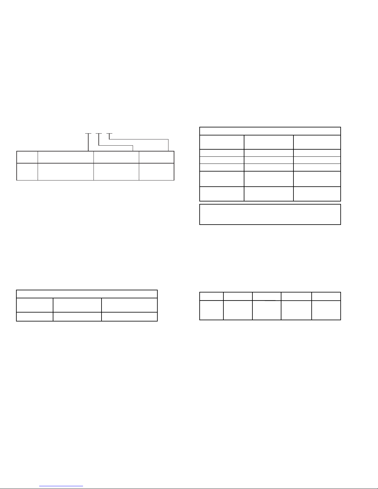
Grundwerte
Temperatur-
koeffizient
Grund-
GenauigkeitEingangsart
WTH
Lin. R
Volt
TE-Typ:
E, J, K, L, N, T, U
TE-Typ: B, R, S,
W3, W5, LR
≤ ±0,2°C
≤ ±0,1 Ω
≤ ±10 µV
≤ ±1°C
≤ ±2°C
≤ ±0,01°C/°C
≤ ±10 mΩ/°C
≤ ±1 µV/°C
≤ ±0,05°C/°C
≤ ±0,2°C/°C
EMV-Immunitätswirkung ..................................... < ±0,5% d. Messsp.
Erweiterte EMV-Immunität:
NAMUR NE 21,
A Kriterium, Burst ...................... < ±1% d. Messsp.
Elektrische Daten:
Spezifikationsbereich:
-40°C bis +85°C
Allgemeine Daten:
Versorgungsspannung, DC
Standard .............................................. 7,2...35 V
CSA, FM & ATEX .................................. 7,2...30 VDC
Eigenverbrauch ........................................... 25 mW...0,8 W
Spannungsabfall .......................................... 7,2 VDC
Isolationsspannung, Test / Betrieb .............. 1,5 kVAC / 50 VAC
Aufwärmzeit ................................................. 5 Min.
Kommunikationsschnittstelle ...................... Loop Link
Signal- / Rauschverhältnis .......................... Min. 60 dB
Ansprechzeit (programmierbar) ................... 1...60 s
EEprom Fehlerkontrolle ...............................< 3,5 s
Signaldynamik, Eingang .............................. 20 bit
Signaldynamik, Ausgang ............................. 16 bit
Kalibrierungstemperatur .............................. 20...28 °C
Genauigkeit, höherer Wert von allgemeinen und Grundwerten:
42
5331
-40°C…+85°C : 3 1500 VAC : B
Umgebungs-
temperatur
Galvanische
Tre nn ung
Typ Version
Bestellangaben: 5331
Standard : A
CSA, FM & ATEX : D
Allgemeine Werte
Temperatur-
koeffizient
Absolute
GenauigkeitEingangsart
Alle
≤ ±0,05% d. Messsp.
≤ ±0,01% d. Messsp./°C
WTH-Typ Min. Wert Max. Wert Min. Spanne Norm
Pt100 -200°C +850°C 25°C IEC 60751
Ni100 -60°C +250°C 25°C DIN 43760
Lin. R 0 Ω 5000 Ω 30 Ω −−−−−
Page 24

EEx- / I.S.-Zulassung - 5331D:
KEMA 06ATEX0062 X ................................. II 1 GD, T80°C...T105°C
EEx ia IIC T6 / T4
Max. Umgebungstemp. für T1...T4 ............. 85°C
Max. Umgebungstemp. für T5 und T6 ........ 60°C
ATEX, für Anwendung in Zone .................... 0, 1, 2, 20, 21 oder 22
Ex- / I.S.-Daten:
Signalausgang / Versorgung, Klemmen 1 bis 2:
Ui ................................................................. : 30 VDC
Ii .................................................................. : 120 mADC
Pi ................................................................. : 0,84 W
Li ................................................................. : 10 µH
Ci ................................................................. : 1 nF
Fühlereingang, Klemmen 3, 4, 5, und 6:
Uo ............................................................... : 9,6 VDC
I o ................................................................ : 25 mA
Po ................................................................ : 60 mW
L o ................................................................ : 33 mH
Co ............................................................... : 2,4 µF
FM, für Anwendung in ................................. IS, Class I, Div. 1, Group A, B, C, D
IS, Class I, Zone 0, AEx ia IIC
FM Installation Drawing No. ................ 5300Q502
CSA, für Anwendung in ............................... IS, Class I, Div. 1, Group A, B, C, D,
IS, Class I, Zone 0, Ex ia IIC
CSA Installation Drawing No. .............. 533XQC03
Marine-Zulassung:
Det Norske Veritas, Ships & Offshore ......... Standard for Certification No. 2.4
GOST R Zulassung:
VNIIM & VNIIFTRI, Cert. no. ........................ Siehe www.prelectronics.de
Eingehaltene Richtlinien: Norm:
EMV 2004/108/EG ....................................... EN 61326-1
ATEX 94/9/EC .............................................. EN 50014, EN 50020, EN 50284,
IEC 61241-0 und IEC 61241-11
FM ............................................................... 3600, 3611, 3610
CSA, CAN / CSA ......................................... C22.2 No. 157, E60079-11, UL 913
d. Messspanne = der gewählten Messspanne
45
TE-Eingang:
Max. Nullpunktverschiebung (Offset) ......... 50% des gewählten Maximalwertes
Vergleichstellenkompensation (CJC) .......... < ±1,0°C
Fühlerfehlererkennung ................................ Ja
Fühlerfehlerstrom:
Bei Erkennung ...................................... Nom. 33 mA
Sonst .................................................... 0 mA
Spannungseingang:
Messbereich ............................................... -12...800 mV
Min. Messbereich (Spanne) ........................ 5 mV
Max. Nullpunktverschiebung (Offset) ......... 50% des gewählten Maximalwertes
Eingangswiederstand ................................. 10 MΩ
Ausgang:
Stromausgang:
Signalbereich .............................................. 4...20 mA
Min. Signalbereich ...................................... 16 mA
Aktualisierungszeit ..................................... 440 ms
Ausgangssignal bei EEpromfehler ............. ≤ 3,5 mA
Belastungswiederstand .............................. ≤ (U
Versorg.
- 7,2) / 0,023 [Ω]
Belastungsstabilität .......................................... < ±0,01% d. Messsp. / 100 Ω
Sensorfehlanzeige:
Programmierbar ......................................... 3,5...23 mA
NAMUR NE43 aufsteuernd ........................ 23 mA
NAMUR NE43 zusteuernd ......................... 3,5 mA
44
Ty p
Min.
Temperatur
Max.
Temperatur
Min.
Spanne Norm
B
E
J
K
L
N
R
S
T
U
W3
W5
LR
+400°C
-100°C
-100°C
-180°C
-100°C
-180°C
-50°C
-50°C
-200°C
-200°C
0°C
0°C
-200°C
+1820°C
+1000°C
+1200°C
+1372°C
+900°C
+1300°C
+1760°C
+1760°C
+400°C
+600°C
+2300°C
+2300°C
+800°C
200°C
50°C
50°C
50°C
50°C
100°C
200°C
200°C
50°C
75°C
200°C
200°C
50°C
IEC584
IEC584
IEC584
IEC584
DIN 43710
IEC584
IEC584
IEC584
IEC584
DIN 43710
ASTM E988-90
ASTM E988-90
GOST 3044-84
Page 25
47
0...16
mA
4
3
2
1
5
6
4
3
2
+
-
+
-
mV
mA
MUX
4 mA
5331
PGA
D / A
Comu.
A / D
CPU
EEPROM
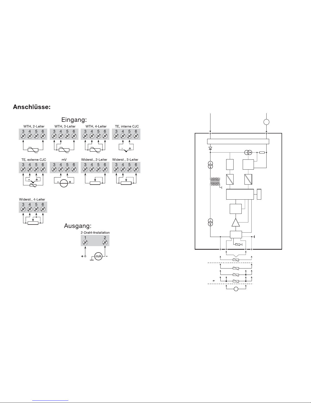
BLOCKDIAGRAMM:
Eingang Masse
Versorgung -
4...20 mA
TE
Ext.
CJC
mV
WTH, lin. R
- Draht
Int.
CJC
Ex-Kreislauf, nur 5331D
Versorgung +
7,2...35 VDC
46
Page 26
APPENDIX
FM Installation Drawing No. 5300Q502
CSA Installation Drawing No. 533XQC03
49
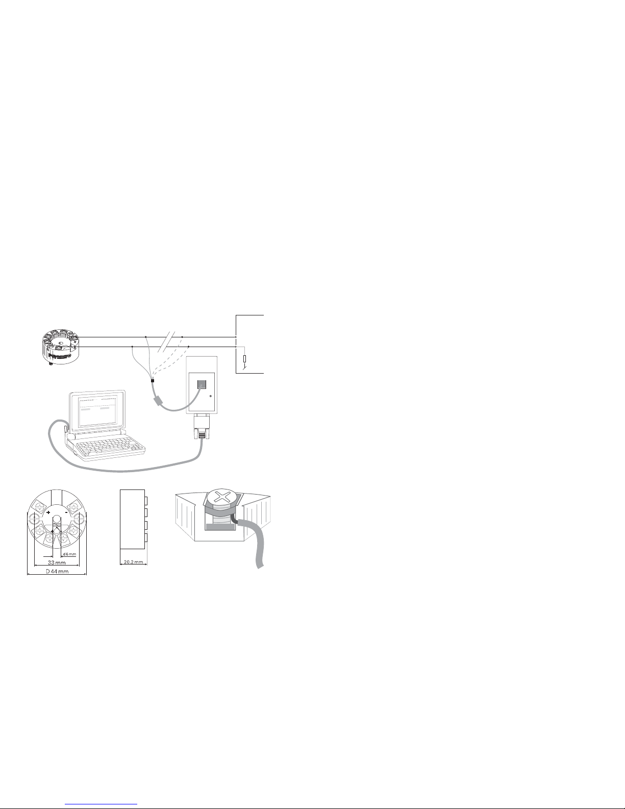
Programmierung:
• Loop Link ist eine batteriegespeiste Schnittstelle zur Programmierung des
PRetop 5331.
• Bezüglich Programmierung verweisen wir auf die nachfolgende Zeichnung
und die “Hilfe”-Funktion im PReset-Programm.
• Loop Link darf nicht zur kommunikation mit Modulen, die in Ex-gefährdeten
Bereichen installiert sind, benutz werden.
Bestellangabe: Loop Link
Abmessungen: Montage von Fühlerleitungen:
48
PRetop 5331
1
2
F
i
l
e
P
r
o
d
u
c
t
I
n
p
u
t
O
u
t
p
u
t
C
o
m
m
u
n
i
c
a
t
i
o
n
L
a
n
g
u
a
g
e
O
p
t
i
o
n
0
8
:
3
0
:
0
0
P
R
e
t
o
p
5
3
3
1
D
a
t
e
:
1
9
9
4
-
8
-
1
0
9
4
3
2
0
1
5
9
4
P
R
e
l
e
c
t
r
o
n
i
c
s
A
n
a
l
o
g
i
n
p
u
t
A
n
a
l
o
g
o
u
t
p
u
t
S
e
r
i
a
l
n
o
:
I
n
p
u
t
t
y
p
e
:
O
u
t
p
u
t
t
y
p
e
:
4
-
2
0
m
A
U
p
s
c
a
l
e
S
e
n
s
o
r
e
r
r
o
r
:
P
t
1
0
0
D
I
N
/
I
E
C
0
.
0
0
-
5
0
.
0
0
C
3
-
w
i
r
e
1
.
0
0
s
e
c
-
-
-
-
-
-
I
n
p
u
t
r
a
n
g
e
:
C
o
n
n
e
c
t
i
o
n
:
C
o
l
d
j
u
n
c
t
i
o
n
c
o
m
p
:
R
e
s
p
o
n
s
e
t
i
m
e
:
T
a
g
n
o
:
*
*
COM
Loop Link
Unterbrechen
+V
B
* Nur anzuschliessen, wenn on-line
(im Betrieb) konfiguriert werden soll.
Schwarz
Rot
Gelb
Grün
Eingang
Betriebsspannung
Anschlussstelle
Die Leitungen müssen zwischen den
Metallplatten montiert werden.
Page 27
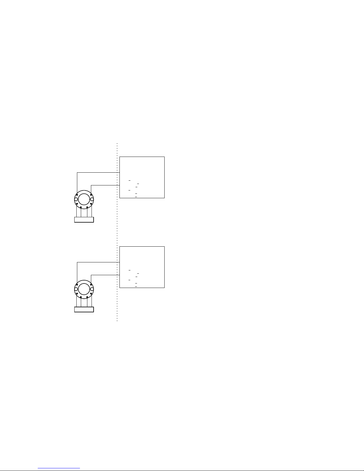
50
5300Q502.doc 2005-12-16 Rev. AD
2/2
The entity concept.
The Transmitter must be installed according to National Electrical Code
(ANSI-NFPA 70).
When installed in Class II locations the Transmitter shall be installed in an enclosure
with a specified ingress protections of IP6X according to IEC60529 and Dust-tight
conduit seals must be used.
Equipment that is FM-approved for intrinsic safety may be connected to barriers based
on the ENTITY CONCEPT. This concept permits interconnection of approved transmitters, meters and other devices in combinations which have not been specifically
examined by FM, provided that the agency's criteria are met. The combination is then
intrinsically safe, if the entity concept is acceptable to the authority having jurisdiction
over the installation.
The entity concept criteria are as follows:
The intrinsically safe devices, other than barriers, must not be a source of power.
The maximum voltage Ui(V
MAX
) and current Ii(I
MAX
), and maximum power Pi(Pmax),
which the device can receive and remain intrinsically safe, must be equal to or greater
than the voltage (Uo or V
OC
or Vt) and current (Io or ISC or It) and the power Po which
can be delivered by the barrier.
The sum of the maximum unprotected capacitance (C
i
) for each intrinsically device and
the interconnecting wiring must be less than the capacitance (C
a
) which can be safely
connected to the barrier.
The sum of the maximum unprotected inductance (L
i
) for each intrinsically device and
the interconnecting wiring must be less than the inductance (L
a
) which can be safely
connected to the barrier.
The entity parameters Uo,V
OC
or Vt and Io,ISC or It, and Ca and La for barriers are
provided by the barrier manufacturer.
5300Q502.doc 2005-12-16 Rev. AD
1/2
Installation Drawing 5300Q502.
Model 5331C,5331D, 5333C and 5333D
Non Hazardous Location
Hazardous (Classified) Location
Associated Apparatus
or Barrier
with
entity Parameters:
SENSOR
1
2
3
45
6
UM < 250V
Voc or Uo < Vmax or Ui
Isc or Io < Imax or Ii
Po < Pi
Ca or Co > Ci + Ccable
La or Lo > Li + Lcable
This device must not be
connected to any associated
apparatus which uses or
generates more than 250 VRMS
+
-
Terminal 1 , 2
Vmax or Ui: 30 V
Imax or Ii: 120 mA
Pmax or Pi: 0.84 W
Ci: 1 nF
Li:10 uH
Terminal 3,4,5,6
Only passive, or non-energy
storing devices such as RTD's
and Thermocouples may be
connected.
Ambient temperature limits
T4: -40 to + 85 deg. Celcius
T6: -40 to + 60 deg. Celcius
Class I,Division1, Groups, A,B,C,D
Class II Division 1 Groups E,F,G or
Class I, Zone 0, IIC
Model 5335C, 5335D.
Non Hazardous Location
Hazardous (Classified) Location
Associated Apparatus
or Barrier
with
entity Parameters:
SENSOR
1
2
3
45
6
UM < 250V
Voc or Uo < Vmax or Ui
Isc or Io < Imax or Ii
Po < Pi
Ca or Co > Ci + Ccable
La or Lo > Li + Lcable
This device must not be
connected to any associated
apparatus which uses or
generates more than 250 VRMS
+
-
Terminal 1 , 2
Vmax or Ui: 30 V
Imax or Ii: 120 mA
Pmax or Pi: 0.84 W
Ci: 1 nF
Li:10 uH
Terminal 3,4,5,6
Vt or Uo: 9.6 V
It or Io: 28 mA
Pt or Po: 67.2 mW
Ca or Co: 3.5 uF
La or Lo: 35 mH
Ambient temperature limits
T4: -40 to + 85 deg. Celcius
T6: -40 to + 60 deg. Celcius
Class I,Division1, Groups, A,B,C,D
Class II Division 1 Groups E,F,G or
Class I, Zone 0, IIC
51
Page 28
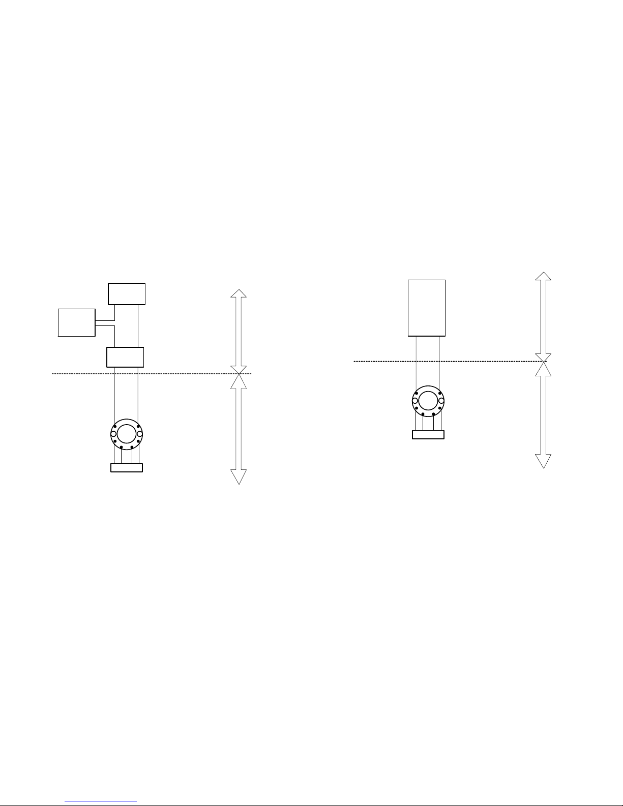
5352
533XQC03.DOC 2006-01-04 Rev. AB 1/2
CSA Installation Drawing 533XQC03.
5331D, 5333D and 5335D transmitters are intrinsically safe in Zone 0 Group IIC
or Class I, Division1, Group A,B,C,D when installed according to Installation
Drawing.
1. Connections with separate power supply and receiver.
Output: Standard 4 – 20 mA loop
Non
hazardous
Location
max. 250 V
T4:-40 to + 85 deg. Celcius
T6:-40 to + 60 deg. Celcius
Separate Power
Supply
Receiving
Instrument
Hazardous
Locations /
Sécurité
Intrinséque
+
-
-+
-
Ambient temperature limits
Intrinsically safe
Barrier Parameters.
Uo(Voc) =< 30 V
Io(Isc) =< 120 mA
Po =< 0.84 W
CSA approved
Barrier
Terminal: 1-2
Ui(Vmax) = 30 V
Ii(Imax) = 120 mA
Pi = 0.84 W
Ci = 1 nF
Li = 10 uH
Co(Ca)>Sum(Ci+Ccable)
Lo(La)>Sum(Li+Lcable)
+
SENSOR
12
3
45
6
5335D
Terminal: 3,4,5,6
Only passive, or non-energy
storing devices such as
RTD's and Thermocouples
may be connected.
Terminal: 3,4,5,6
Uo(Voc) = 9.6 V
Io(Isc) = 28 mA
Po = 67.2 mW
Co(Ca) = 3.5 uF
Lo(La) = 35 mH
5331D or
5333D
5331D or
5333D or
5335D
Warning:
Substitution of components may impair intrinsic safety.
The transmitters must be installed in a suitable enclosure to meet installation
codes stipulated in the Canadian Electrical Code (CEC).
533XQC03.DOC 2006-01-04 Rev. AB 2/2
2. Connection with power
supply and barrier built into receiver.
Output: Standard 4 - 20 mA loop
Nonhazardous
location
max. 250 V
Hazardous
Locations /
Sécurité
Intrinséque
Transmitter
Power Supply
built into
CSA approved
Receiving
Instrument
Ambient temperature limits
T4: -40 to + 85 deg. Celcius
T6: -40 to + 60 deg. Celcius
Intrinsically safe
Barrier Parameters.
Uo(Voc) =< 30 V
Io(Isc) =< 120 mA
Po(Pmax) =< 0.84 W
Ca>Sum(Ci)+Ccable
La>Sum(Li)+Lcable
SENSOR
12
3
45
6
+ -
5331D or
5333D or
5335D
Terminal: 3,4,5,6
Uo(Voc) = 9.6 V
Io(Isc) = 28 mA
Po = 67.2 mW
Co(Ca) = 3.5 uF
Lo(La) = 35 mH
Terminal: 3,4,5,6
Only passive, or non-energy
storing devices such as
RTD's and Thermocouples
may be connected.
Terminal: 1-2
Ui(Vmax) = 30 V
Ii(Imax) = 120 mA
Pi = 0.84 W
Ci = 1 nF
Li =10uH
5331D or
5333D
5335D
Warning:
Substitution of components may impair intrinsic safety.
The Transmitters must be installed in a suitable enclosure to meet installation
codes stipulated in the Canadian Electrical Code (CEC).
Page 29
PR electronics A/S tilbyder et bredt program af analoge og digitale signalbehandlingsmoduler til industriel automation. Vores
kompetenceområder omfatter: Isolation, Displays, Ex-interfaces,
Temperatur samt Universal-moduler. Alle produkter opfylder de
strengeste internationale standarder, og størstedelen integrerer
den patenterede STREAM-SHIELD teknologi, der sikrer driftsikkerhed i selv de værste omgivelser. Vores motto »Signals the Best«
er indbegrebet af denne fi losofi – og din garanti for kvalitet.
PR electronics A/S offers a wide range of analogue and digital
signal conditioning modules for industrial automation. Our
areas of competence include: Isolation, Displays, Ex interfaces,
Temperature, and Universal Modules. All products comply with
the most exacting international standards and the majority
feature our patented STREAM-SHIELD technology ensuring
reliability in even the worst of conditions. »Signals the Best« is
the epitome of our philosophy – and your guarantee for quality.
PR electronics A/S offre une large gamme de produits pour le
traitement des signaux analogiques et numériques dans tous les
domaines industriels. Nos compétences s’étendent des
transmetteurs de température aux affi cheurs, des isolateurs aux
interfaces SI, jusqu’aux modules universels. Tous nos produits
sont conformes aux normes internationales les plus strictes et la
majorité d’entre eux répondent même à la technologie brevetée
STREAM-SHEILD qui garantie un fonctionnement fi able sous
les conditions les plus défavorables. Notre devise »SIGNALS the
BEST« c’est notre ligne de conduite - et pour vous l’assurance
de la meilleure qualité.
PR electronics A/S verfügt über ein breites Produktprogramm an
analogen und digitalen Signalverarbeitungsmodule für die industrielle Automatisierung. Unsere Kompetenzbereiche umfassen:
Displays, Temperaturtransmitter, Ex- und galvanische Signaltrenner, und Universalgeräte. Alle Produkte von PR electronics
werden in Überein stimmung mit den strengsten internationalen
Normen produziert. Für die Mehrzahl aller Produkte garantiert
die patentierte STREAM-SHIELD Technologie höchste Zuverlässigkeit auch unter schwierigsten Einsatzbedingungen. »Signals
the Best« ist Ihre Garantie für Qualität!
DK
UK
FR
DE
Subsidiaries
France
PR electronics Sarl
Zac du Chêne, Activillage
4, allée des Sorbiers
F-69673 Bron Cedex
Germany
PR electronics GmbH
Bamlerstraße 92
D-45141 Essen
Italy
PR electronics S.r.l.
Via Giulietti, 8
IT-20132 Milano
Spain
PR electronics S.L.
Avda. Meridiana 354, 9°
B
E-08027 Barcelona
Sweden
PR electronics AB
August Barks gata 6A
S-421 32 Västra Frölunda
UK
PR electronics UK Ltd
Middle Barn, Apuldram
Chichester
West Sussex, PO20 7FD
USA
PR electronics Inc
11225 West Bernardo Court
Suite A
San Diego, California 92127
[email protected]
tel. +33 (0) 4 72 14 06 07
fax +33 (0) 4 72 37 88 20
[email protected]
tel. +49 (0) 201 860 6660
fax +49 (0) 201 860 6666
[email protected]
tel. +39 02 2630 6259
fax +39 02 2630 6283
[email protected]
tel. +34 93 311 01 67
fax +34 93 311 08 17
[email protected]
tel. +46 (0) 3149 9990
fax +46 (0) 3149 1590
[email protected]
tel. +44 (0) 1243 776 450
fax +44 (0) 1243 774 065
[email protected]
tel. +1 858 521 0167
fax +1 858 521 0945
Head offi ce
Denmark www.prelectronics.com
PR electronics A/S [email protected]
Lerbakken 10 tel. +45 86 37 26 77
DK-8410 Rønde fax +45 86 37 30 85
 Loading...