

Page 1
Programmable displays with a wide selection of inputs and outputs for display of temperature,
volume and weight, etc. Feature linearisation, scaling,
and difference measurement functions for programming
via PReset software.
Interfaces for analogue and digital
signals as well as HART
®
signals between sensors / I/P
converters / frequency signals and control systems in Ex
zone 0, 1 & 2 and for some modules in zone 20, 21 & 22.
Galvanic isolators for analogue and digital
signals as well as HART
®
signals. A wide product range
with both loop-powered and universal isolators featuring
linearisation, inversion, and scaling of output signals.
PC or front programmable modules with
universal options for input, output and supply. This range
offers a number of advanced features such as process
calibration, linearisation and auto-diagnosis.
A wide selection of transmitters for DIN
form B mounting and DIN rail modules with analogue
and digital bus communication ranging from applicationspecific to universal transmitters.
Displays
Temperature
Isolation
Ex interfaces
Universal
DK
UK
FR
DE
Side 1
Page 25
Page 49
Seite 73
S I G N A L S T H E B E S T
4 1 1 4
U n i v e r s a l
T r a n s m i t t e r
N o . 4 1 1 4 V 1 0 3 - I N ( 1 0 0 5 )
F r o m s e r . n o . 0 9 0 3 9 0 0 0 1
Page 2

1
UNIVERSAL TRANSMITTER
PReasy 4114
INDHOLDSFORTEGNELSE
Advarsler ............................................................................ 2
Sikkerhedsregler ................................................................. 3
Overensstemmelseserklæring ............................................ 5
Afmontering af SYSTEM 4000 ........................................... 6
Når LED i front lyser rødt / display viser AO.ER ................ 6
Avancerede features........................................................... 7
Anvendelse ......................................................................... 7
Teknisk karakteristik ........................................................... 7
PR 4501 Display- / programmeringsfront .......................... 8
Applikationer ...................................................................... 9
Bestillingsnumre ................................................................. 10
Elektriske specifikationer.................................................... 10
Displayvisning på 4501 af følerfejlsdetektering og
indgangssignal uden for område ................................... 13
Grænser for følerfejlsdetektering ....................................... 14
Fejlvisninger ........................................................................ 14
Tilslutninger ........................................................................ 15
Blokdiagram ....................................................................... 16
Programmering / betjening af trykknapper ........................ 17
Rutediagram ....................................................................... 20
Rutediagram, avancerede indstillinger (ADV.SET) .............. 22
Rullende hjælpetekster i displaylinie 3 ............................... 23
Page 3
2
3
SIGNATURFORKLARING
Trekant med udråbstegn: Advarsel / krav. Hændelser der kan føre til livs-
truende situationer.
CE-mærket er det synlige tegn på modulets overensstemmelse med
EU -direktivernes krav.
Dobbelt isolation er symbolet for, at modulet overholder ekstra krav til
isolation.
SIKKERHEDSREGLER
DEFINITIONER:
Farlige spændinger er defineret som områderne: 75...1500 Volt DC og
50...1000 Volt AC.
Teknikere er kvalificerede personer, som er uddannet eller oplært til at kunne
udføre installation, betjening eller evt. fejlfinding både teknisk og sikkerhedsmæssigt forsvarligt.
Operatører er personer, som under normal drift med produktet skal indstille og
betjene produktets trykknapper eller potentiometre, og som er gjort bekendt
med indholdet af denne manual.
MODTAGELSE OG UDPAKNING:
Udpak modulet uden at beskadige det. Kontrollér ved modtagelsen, at modultypen svarer til den bestilte. Indpakningen bør følge modulet, indtil dette er monteret på blivende plads.
MILJØFORHOLD:
Undgå direkte sollys, kraftigt støv eller varme, mekaniske rystelser og stød, og
udsæt ikke modulet for regn eller kraftig fugt. Om nødvendigt skal opvarmning,
ud over de opgivne grænser for omgivelsestemperatur, forhindres ved hjælp af
ventilation.
Alle moduler hører til Installationskategori II, Forureningsgrad 1 og Isolationsklasse II.
INSTALLATION:
Modulet må kun tilsluttes af teknikere, som er bekendte med de tekniske
udtryk, advarsler og instruktioner i manualen, og som vil følge disse.
Hvis der er tvivl om modulets rette håndtering, skal der rettes henvendelse til
den lokale forhandler eller alternativt direkte til:
ADVARSEL
SYSTEM 4000 skal monteres på DIN-skinne efter DIN 46277.
INSTAL-
LATION
ADVARSEL
Dette modul er beregnet for tilslutning til livsfarlige elektriske
spændinger. Hvis denne advarsel ignoreres, kan det føre til
alvorlig legemsbeskadigelse eller mekanisk ødelæggelse.
For at undgå faren for elektriske stød og brand skal manualens
sikkerhedsregler overholdes, og vejledningerne skal følges.
Specifikationerne må ikke overskrides, og modulet må kun
benyttes som beskrevet i det følgende.
Manualen skal studeres omhyggeligt, før modulet tages i brug.
Kun kvalificeret personale (teknikere) må installere dette modul.
Hvis modulet ikke benyttes som beskrevet i denne manual, så
forringes modulets beskyttelsesforanstaltninger.
GENERELT
ADVARSEL
Der må ikke tilsluttes farlig spænding til modulet, før dette
er fastmonteret, og følgende operationer bør kun udføres på
modulet i spændingsløs tilstand og under ESD-sikre forhold:
Installation, ledningsmontage og -demontage.
Fejlfinding på modulet.
Reparation af modulet og udskiftning af sikringer må kun
foretages af PR electronics A/S.
FARLIG
SPÆNDING
ADVARSEL
Modulets frontplade må ikke åbnes, da dette vil medføre skade
på stikforbindelsen til display- / programmeringsfronten PR
4501. Modulet indeholder ingen DIP-switche eller jumpere.
Page 4

4
5
OVERENSSTEMMELSESERKLÆRING
Som producent erklærer
PR electronics A/S
Lerbakken 10
DK-8410 Rønde
hermed at følgende produkt:
Type: 4114
Navn: Universal transmitter
er i overensstemmelse med følgende direktiver og standarder:
EMC-direktivet 2004/108/EF og senere tilføjelser
EN 61326-1
For specifikation af det acceptable EMC-niveau henvises til modulets
elektriske specifikationer.
Lavspændingsdirektivet 2006/95/EF og senere tilføjelser
EN 61010-1
Rønde, 20. august 2009 Kim Rasmussen
Producentens underskrift
PR electronics A/S, Lerbakken 10, 8410 Rønde,
Danmark, tlf: +45 86 37 26 77.
Installation og tilslutning af modulet skal følge landets gældende regler for
installation af elektrisk materiel bl.a. med hensyn til ledningstværsnit, for-sikring
og placering.
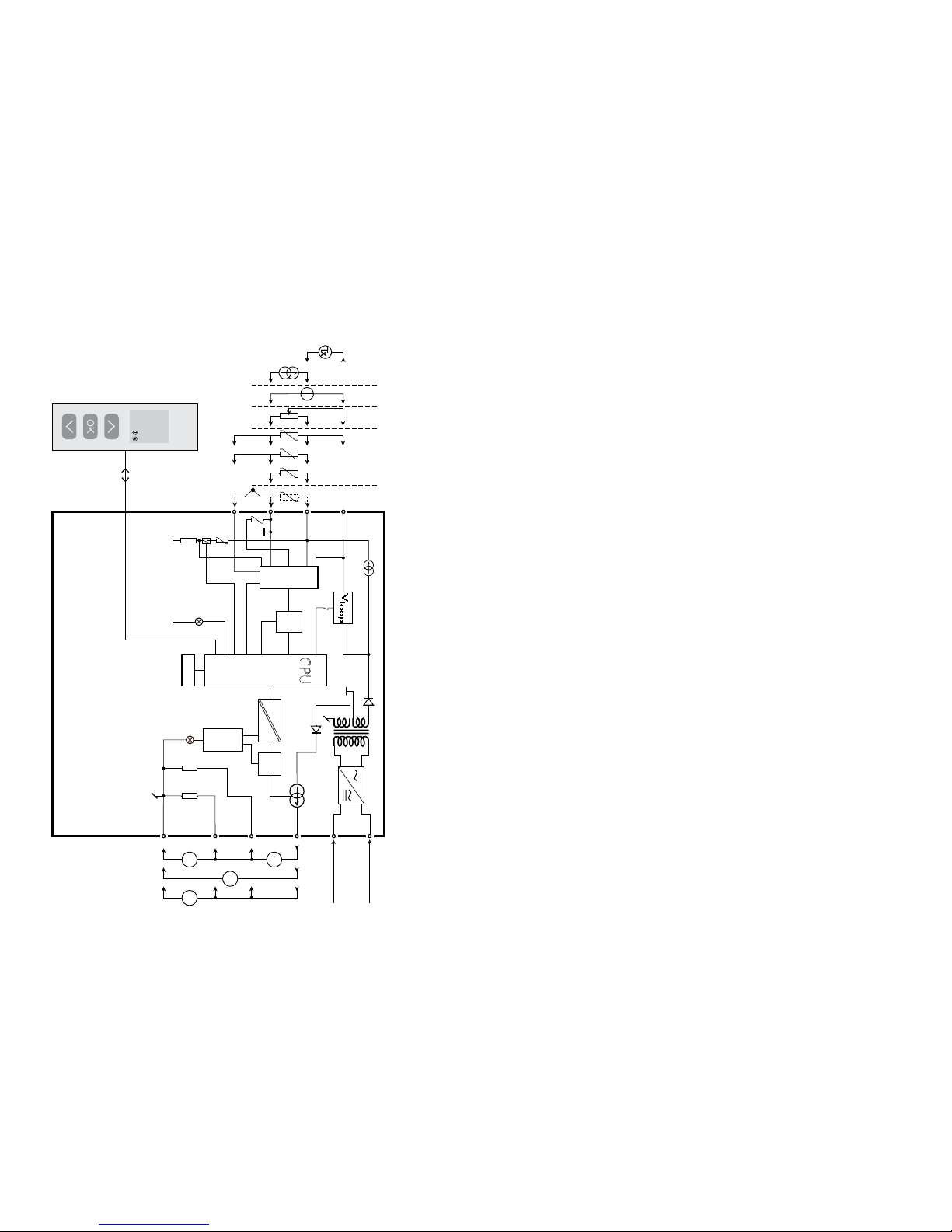
Beskrivelse af indgang / udgang og forsyningsforbindelser findes på blokdiagrammet og sideskiltet.
For moduler, som er permanent tilsluttet farlig spænding, gælder:
For-sikringens maksimale størrelse er 10 A, og den skal sammen med
en afbryder placeres let tilgængeligt og tæt ved modulet. Afbryderen
skal mærkes således, at der ikke er tvivl om, at den afbryder spændingen til modulet.
Produktionsår fremgår af de to første cifre i serienummeret.
UL-INSTALLATIONSKRAV:
Brug kun 60/75°C kobberledninger
Må kun anvendes i forureningsgrad 2 eller bedre
Max. omgivelsestemperatur ................... 60°C
Max. ledningskvadrat, ............................ AWG 26-14
UL fil-nummer......................................... E231911
KALIBRERING OG JUSTERING:
Under kalibrering og justering skal måling og tilslutning af eksterne spændinger
udføres i henhold til denne manual, og teknikeren skal benytte sikkerhedsmæssigt korrekte værktøjer og instrumenter.
BETJENING UNDER NORMAL DRIFT:
Operatører må kun indstille eller betjene modulerne, når disse er fast installeret
på forsvarlig måde i tavler el. lignende, så betjeningen ikke medfører fare for liv
eller materiel. Dvs., at der ikke er berøringsfare, og at modulet er placeret, så
det er let at betjene.
RENGØRING:
Modulet må, i spændingsløs tilstand, rengøres med en klud let fugtet med
destilleret vand.
ANSVAR:
I det omfang instruktionerne i denne manual ikke er nøje overholdt, vil kunden
ikke kunne rette noget krav, som ellers måtte eksistere i henhold til den indgåede salgsaftale, mod PR electronics A/S.
Page 5
6
7
UNIVERSAL TRANSMITTER
PREASY 4114
• Indgang for RTD, TC, Ohm, potentiometer, mA og V
• 2-trådsforsyning > 16 V
• FM-godkendt til installation i Div. 2
• Strøm- og spændingsudgang
• Universel forsyning med AC eller DC
Avancerede features:
• Programmerbar via aftagelig displayfront (4501), proceskalibrering, signalsimulering, passwordsbeskyttelse, fejldiagnosticering og valg af hjælpetekster
på flere sprog.
Anvendelse:
• Lineariseret elektronisk temperaturmåling med modstandsføler eller termoelementføler.
• Omsætning af lineær modstandsændring til standard analogt strøm- / spændingssignal, f.eks. fra ventiler, spjæld eller lineære bevægelser med påmonteret potentio meter.
• Spændingsforsyning og signalisolator for 2-trådstransmittere.
• Styring af procesforløb med standard analog udgang.
• Galvanisk adskillelse af analoge signaler og måling af ikke-stelbundne signaler.
• 4114 er konstrueret med et højt sikkerhedsniveau, så den er anvendelig i
SIL 2 installationer.
Teknisk karakteristik:
• Med påmonteret display- / programmeringsfront kan alle driftsparametre tilpasses enhver applikation. Elektroniske hardwareswitche betyder, at modulet
ikke skal åbnes for indstilling af dipswitche.
• Grøn / rød LED i front, der indikerer normal drift og funktionsfejl.
• Der er løbende sikkerhedscheck af gemte data.
• 3-port 2,3 kVAC galvanisk isolation.
AFMONTERING AF SYSTEM 4000
Husk først at demontere tilslutningsklemmerne med farlig spænding.
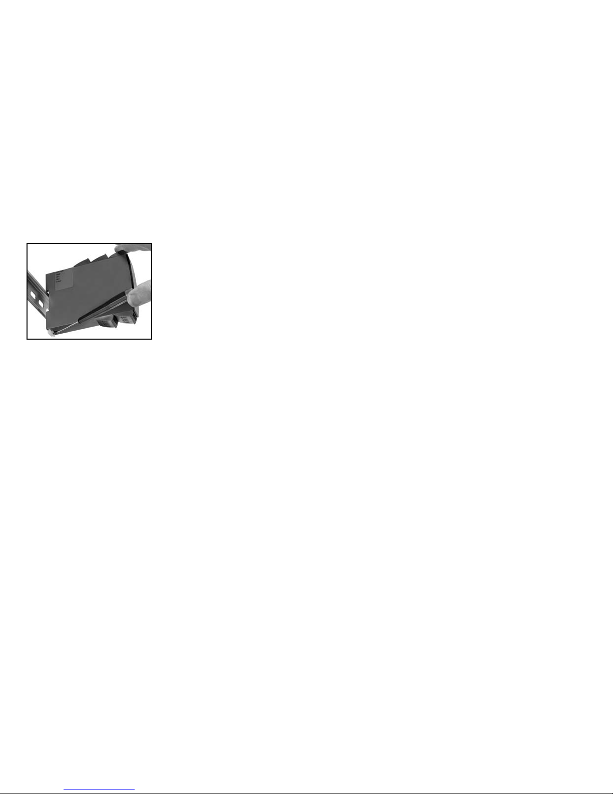
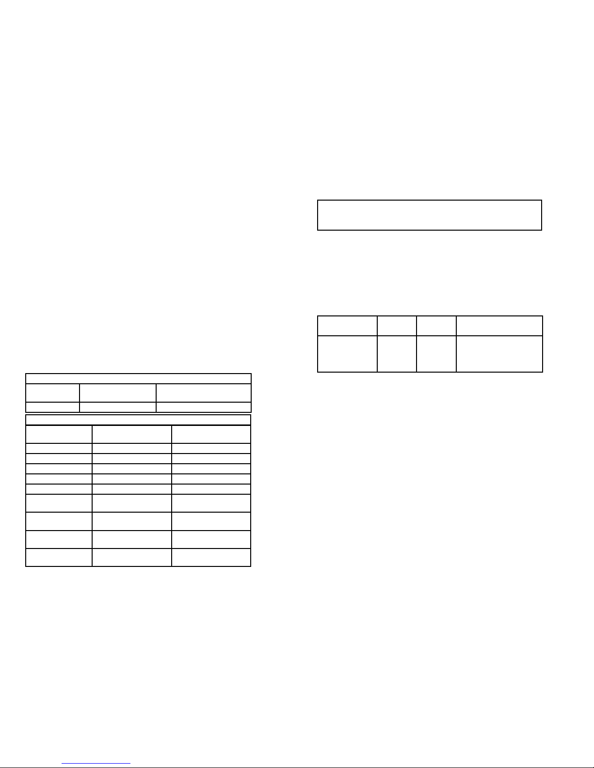
Billede 1:
Modulet frigøres fra DIN-skinnen ved
at løfte i den nederste lås.
Når LED i front lyser rødt / display viser AO.ER:
PR 4114 er udviklet som en SIL 2 enhed med et højt sikkerhedsniveau. Derfor
foretages der på et 4...20 mA udgangssignal en kontinuerlig måling af den
strøm, der sendes ud af modulet. Hvis denne strøm er 0, indtræffer en fejlmode, som tænder den røde front-LED. Hvis funktionen ønskes, kan den
tilvælges i menuen, da det ikke er en default option. Hvis enheden er i fejlmode, kan den kun resettes ved at slukke og tænde forsyningsspændingen
til modulet.
Page 6
+
-
+
-
44
43
42
41
12
14
13
11
+
-
10 V
1 V
+
-
10 V
1 V
33
32
31
*
8
9
PR 4501 DISPLAY- / PROGRAMMERINGSFRONT
Funktionalitet:
Den enkle PReasy menustruktur og de forklarende hjælpetekster leder dig automatisk gennem opsætningen, og
gør produktet meget enkelt at anvende. Se beskrivelse
af funktioner og opsætningsmuligheder under afsnittet
”Progammering / betjening af trykknapper”.
Anvendelse:
• Kommunikationsinterface til ændring af driftsparametre i 4114.
• Kan flyttes fra en 4114 til en anden 4114 og downloade den første transmitters opsætning til efterfølgende transmittere.
• Som fastmonteret display til visualisering af procesdata og status.
Teknisk karakteristik:
• Fire liniers LCD-display; linie 1 (5,57 mm høj) viser indgangssignal, linie 2
(3,33 mm høj) viser enheder - UNIT, linie 3 (3,33 mm høj) viser analog udgang
eller TAG-nr. og linie 4 viser status for kommunikation.
• Programmeringsadgang kan forhindres ved indkodning af et password.
Passwordet gemmes i transmitteren, så sikkerheden mod uønskede ændringer er så høj som muligt.
Montage / installation:
• Klikkes på fronten af 4114.
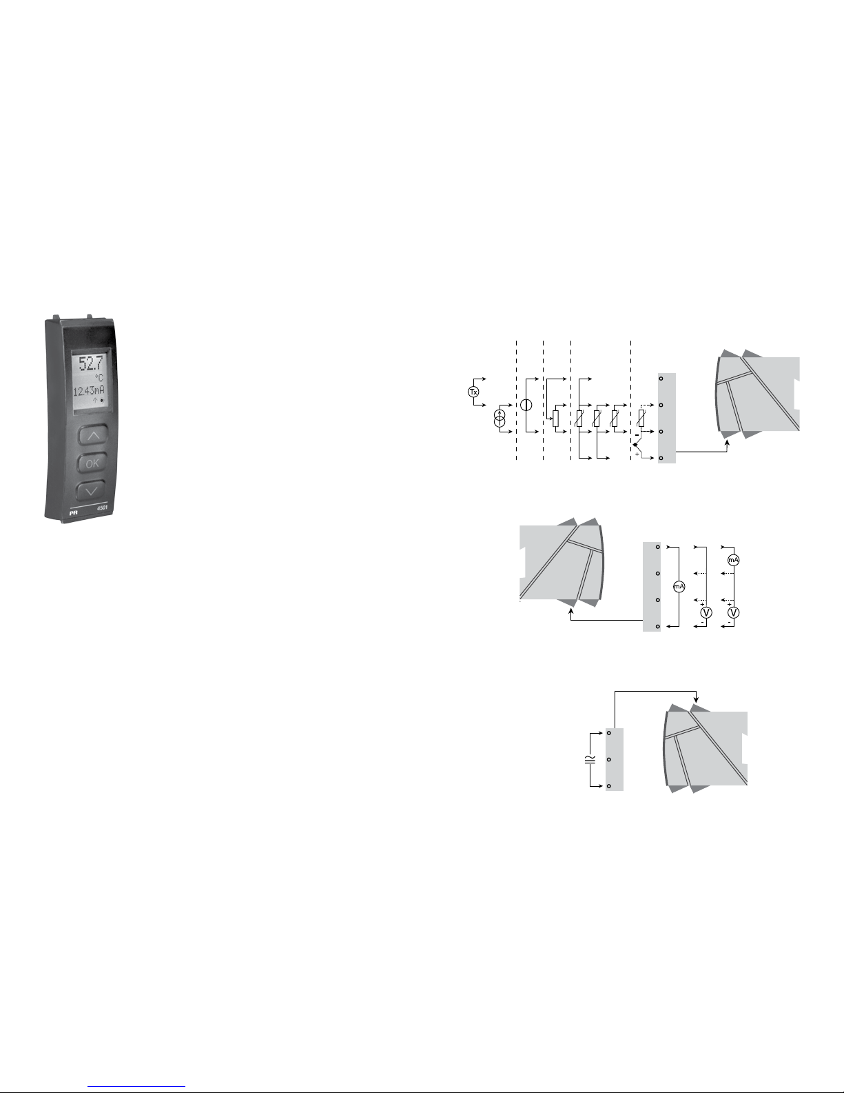
APPLIKATIONER
Indgangssignaler:
Strøm
Spæn-
ding
Potenti-
ometer
RTD og lin.R TC
Forbindelse, ledere
Udgangssignaler:
Forsyning:
21,6...253 VAC
eller
19,2...300 VDC
Analog, 0/4...20 mA og spænding
*Bestilles særskilt: CJC-klemme 5910.
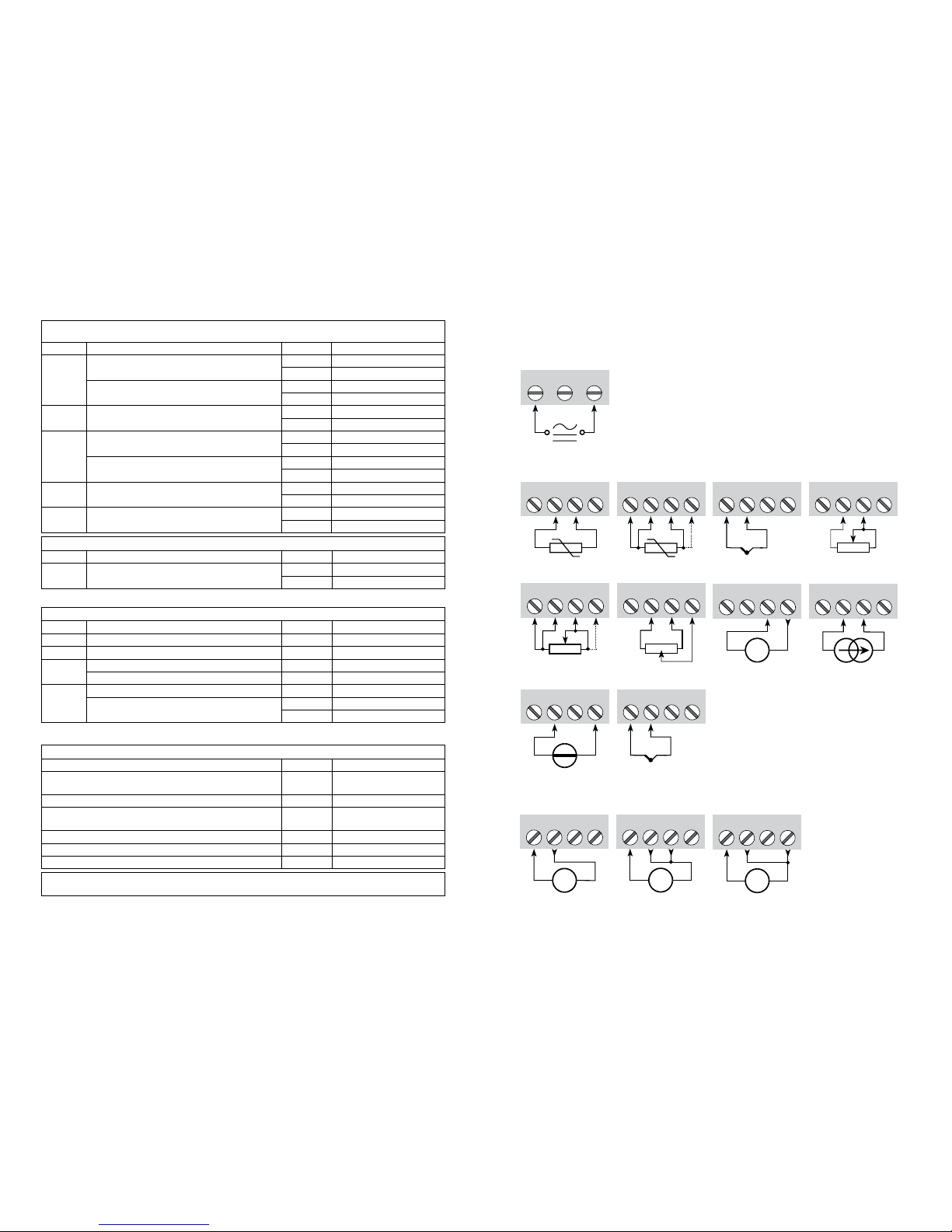
Se tilslutningstegning på side 15.
Page 7
10
11
Hjælpespændinger:
2-trådsforsyning (klemme 44...43) .............. 25...16 VDC / 0...20 mA
Ledningskvadrat (max.) ............................... 1 x 2,5 mm
2
flerkoret ledning
Klemskruetilspændingsmoment .................. 0,5 Nm
Relativ luftfugtighed .................................... < 95% RH (ikke kond.)
Mål, uden displayfront (HxBxD) .................. 109 x 23,5 x 104 mm
Mål, med displayfront (HxBxD) ................... 109 x 23,5 x 116 mm
Kapslingsklasse ........................................... IP20
Vægt ............................................................ 145 g / 160 g med 4501
RTD-, lineær modstands- og potentiometerindgang:
Indgang for RTD-typer:
Pt10, Pt20, Pt50, Pt100, Pt200, Pt250, Pt300, Pt400, Pt500, Pt1000
Ni50, Ni100, Ni120, Ni1000
Kabelmodstand pr. leder, (max.), RTD ........ 50 Ω
Følerstrøm, RTD .......................................... Nom. 0,2 mA
Virkning af følerkabelmodstand
(3- / 4-leder), RTD ....................................... < 0,002 Ω / Ω
Følerfejlsdetektering, RTD ........................... Ja
Kortslutningsdetektering, RTD .................... < 15 Ω
Bestillingsnumre
4114 = Universal transmitter
4501 = Display- / programmeringsfront
5910 = CJC-klemme
Elektriske specifikationer:
Specifikationsområde .................................. -20 til +60°C
Fælles specifikationer:
Forsyningsspænding, universel ................... 21,6...253 VAC, 50...60 Hz eller
19,2...300 VDC
Max. forbrug ................................................ ≤ 2,0 W
Sikring ......................................................... 400 mA T / 250 VAC
Isolationsspænding, test / drift ................... 2,3 kVAC / 250 VAC
Kommunikationsinterface ............................ Programmeringsfront 4501
Signal- / støjforhold ..................................... Min. 60 dB (0...100 kHz)
Reaktionstid (0...90%, 100...10%):
Temperaturindgang ................................. ≤ 1 s
mA- / V-indgang ...................................... ≤ 400 ms
Kalibreringstemperatur ................................ 20...28°C
Nøjagtighed, størst af generelle og basisværdier:
EMC-immunitetspåvirkning ................................. < ±0,5% af span
Udvidet EMC-immunitet:
NAMUR NE 21, A-kriterium, gniststøj ................. < ±1% af span
Indgangs-
type
Min.
værdi
Max.
værdi
Standard
Pt100
Ni100
Lin. R
Potentiometer
-200°C
-60°C
0 Ω
10 Ω
+850°C
+250°C
10000 Ω
100 kΩ
IEC60751
DIN 43760
-
-
Generelle værdier
Indgangstype
Absolut
nøjagtighed
Temperatur-
koefficient
Alle ≤ ±0,1% af span ≤ ±0,01% af span / °C
Basisværdier
Indgangstype
Basis-
nøjagtighed
Temperatur-
koefficient
mA ≤ ±4 µA ≤ ±0,4 µA / °C
Volt ≤ ±20 µV ≤ ±2 µV / °C
Pt100 ≤ ±0,2°C ≤ ±0,01°C / °C
Lin. R ≤ ±0,1 Ω ≤ ±0,01 Ω / °C
Potentiometer ≤ ±0,1 Ω ≤ ±0,01 Ω / °C
TC-type:
E, J, K, L, N, T, U
≤ ±1°C
≤ ±0,05°C / °C
TC-type: R, S,
W3, W5, LR
≤ ±2°C
≤ ±0,2°C / °C
TC-type: B
160...400°C
≤ ±4,5°C
≤ ±0,45°C / °C
TC-type: B
400...1820°C
≤ ±2°C
≤ ±0,2°C / °C
Page 8

12
13
Belastning (max.) ......................................... 20 mA / 800 Ω / 16 VDC
Belastningsstabilitet .................................... ≤ 0,01% af span / 100 Ω
Følerfejlsdetektering .................................... 0 / 3,5 / 23 mA / ingen
NAMUR NE 43 Up- / Downscale ................ 23 mA / 3,5 mA
Begrænsning af udgang:
på 4...20 og 20...4 mA signaler ............... 3,8...20,5 mA
på 0...20 og 20...0 mA signaler ............... 0...20,5 mA
Strømbegrænsning ...................................... ≤ 28 mA
Spændingsudgang:
Signalområde .............................................. 0...10 VDC
Programmerbare signalområder ................. 0...1 / 0,2...1 / 0...10 / 0...5 / 1...5 /
2...10 / 1...0 / 1...0,2 / 5...0 / 5...1 /
10...0 og 10...2 V
Belastning (min.) .......................................... 500 kΩ
Ex- / I.S.-godkendelse:
FM, må anvendes i ...................................... Class I, Div. 2, Group A, B, C, D
Class I, Div. 2, Group IIC
Zone 2
Max. omgivelsestemp. for T5 ...................... 60°C
Marine-godkendelse:
Det Norske Veritas, Ships & Offshore ......... Standard for Certification No. 2.4
GOST R godkendelse:
VNIIM, Cert no.. ........................................... Se www.prelectronics.dk
Overholdte myndighedskrav: Standard:
EMC 2004/108/EF ....................................... EN 61326-1
LVD 2006/95/EF .......................................... EN 61010-1
FM ............................................................... 3600, 3611, 3810 og ISA 82.02.01
UL, Standard for Safety .............................. UL 508
Af span = af det aktuelt valgte område
Displayvisning på 4501 af følerfejlsdetektering og
indgangssignal uden for område:
TC-indgang:
Koldt loddestedskomp. (CJC):
via ekstern føler i klemme 5910 .............. 20...28°C ≤ ± 1°C
-20...20°C /
28...70°C ≤ ± 2°C
via intern CJC-føler ................................. ±(2,0°C + 0,4°C * Δt)
Δt = intern temperatur-omgivelsestemperatur
Følerfejlsdetektering, alle TC-typer ............. Ja
Følerfejlsstrøm:
under detektering .................................... Nom. 2 µA
ellers ........................................................ 0 µA
Strømindgang:
Måleområde ................................................ 0...20 mA
Programmerbare måleområder ................... 0...20 og 4...20 mA
Indgangsmodstand ..................................... Nom. 20 Ω + PTC 50 Ω
Følerfejlsdetektering:
strømsløjfebrud 4...20 mA ....................... Ja
Spændingsindgang:
Måleområde ................................................ 0...12 VDC
Programmerbare måleområder ................... 0...1 / 0,2...1 / 0...5 / 1...5 /
0...10 og 2...10 VDC
Indgangsmodstand ..................................... Nom. 10 MΩ
Strømudgang:
Signalområde (span) ................................... 0...20 mA
Programmerbare signalområder ................. 0...20 / 4...20 / 20...0 / 20...4 mA
Følerfejlscheck:
Modul: Konfiguration Følerfejlsdetektering:
4114
OUT.ERR=NONE. OFF
Ellers: ON
Type
Min.
værdi
Max.
værdi
Standard
B
E
J
K
L
N
R
S
T
U
W3
W5
LR
0°C
-100°C
-100°C
-180°C
-200°C
-180°C
-50°C
-50°C
-200°C
-200°C
0°C
0°C
-200°C
+1820°C
+1000°C
+1200°C
+1372°C
+900°C
+1300°C
+1760°C
+1760°C
+400°C
+600°C
+2300°C
+2300°C
+800°C
IEC 60584-1
IEC 60584-1
IEC 60584-1
IEC 60584-1
DIN 43710
IEC 60584-1
IEC 60584-1
IEC 60584-1
IEC 60584-1
DIN 43710
ASTM E988-90
ASTM E988-90
GOST 3044-84
Page 9
11 12 14
13
+
-
V
11 12 14
13
+
-
V
11 12 14
13
+
-
mA
+
-
41 42 44
43
41 42 44
43
42 44
43
41 41 42 44
43
41 42 44
43
+
-
41 42 44
43
+
-
41 42 44
43
+
-
Tx
41 42 44
43
31 32 33
41 42 44
43
+
-
41 42 44
CJC
14
15
Grænser for følerfejlsdetektering:
Fejlvisninger:
Uden for område visning (IN.LO, IN.HI):
Ved overskridelse af A/D-konverterens eller polynomiets gyldige område.
Indgang Område Visning Grænse
VOLT
0...1 V / 0,2...1 V
IN.LO < -25 mV
IN.HI > 1,2 V
0...10 V / 2...10 V
IN.LO < -25 mV
IN.HI > 12 V
CURR 0...20 mA / 4...20 mA
IN.LO < -1,05 mA
IN.HI > 25,05 mA
LIN.R
0...800
Ω
IN.LO < 0 Ω
IN.HI > 1075 Ω
0...10 kΩ
IN.LO < 0 Ω
IN.HI < 110 kΩ
POTM -
IN.LO < -0,5 %
IN.HI > 100,5 %
TEMP TC / RTD
IN.LO < temperaturområde -2°C
IN.HI > temperaturområde +2°C
Følerfejlsdetektering (SE.BR, SE.SH):
Indgang Område Visning Grænse
CURR Strømsløjfebrud (4...20 mA) SE.BR <= 3,6 mA; > = 21 mA
POTM Alle, SE.BR på alle 3-ledere SE.BR > ca. 126 k
Ω
LIN.R
0...800
Ω SE.BR > ca. 875 Ω
0...10 kΩ SE.BR > ca. 11 kΩ
TEMP
TC SE.BR > ca. 750 k
Ω / (1,25 V)
RTD: 2-, 3- og 4-leder
Ingen SE.SH for Pt10, Pt20 og Pt50
SE.BR > ca. 15 k
Ω
SE.SH < ca. 15 Ω
Display under min.- / over max.-visning (-1999, 9999):
Indgang Område Visning Grænse
Alle Alle
-1999 Displayværdi <-1999
9999 Displayværdi >9999
Visning ved hardwarefejl
Fejlsøgning Visning Årsag
Test af intern CJC-sensor CJ.ER
CJC-sensor defekt eller
tem peratur udenfor område
Checksum test af den aktuelle konfiguration i FLASH FL.ER Fejl i FLASH
Checkmåling af analog udgangsstrøm AO.ER
1) Strømsløjfen er brudt
(kun S4...20 mA/S20...4 mA)
Test af 4501 / 4114 kommunikation NO.CO Fejl i stikforbindelse
Check om indgangssignal passer med indgangskonfiguration IN.ER 1) Fejlniveauer på indgang
Check om gemt konfiguration i 4501 passer med modul TY.ER Konfiguration er ikke 4114
! Alle fejlvisninger i display blinker 1 gang pr. sekund samt suppleres med tilhørende hjælpetekst.
1) Fejlen resettes ved at slukke og tænde for modulet.
TILSLUTNINGER:
Indgange:
Udgange:
Forsyning:
Spænding, 1 V Spænding, 10 VStrøm
RTD, 3- / 4-lederRTD, 2-leder Modstand, 2-leder
Modstand,
3- / 4-leder
Potentiometer
Strøm2-Trådstransmitter
Spænding
TC, intern
CJC-føler
* Bestilles særskilt: 5910 CJC-klemme
*TC,
CJC-klemme
Page 10
50.0
VALVE 5
l / min
4114
4
3
2
+
-
+
-
11
13
14
500Ω
50Ω
33
31
12
D / A
Safety
A / D
PTC
CJC
0.2 mA
43
44
42
41
10 Ω
MUX
EEPROM
CPU
VV
mA
mA
I+
10 V
1 V
+
-
*
16
17
Poten tiome ter
2-trådstransmitter
Spænding
Strøm
RTD og lin.R,
leders
forbindelse
Forsyning
Forsyning
21,6...253 VAC eller
19,2...300 VDC
I + V
Udg.
I
Udg.
V
Udg.
TC
Rød
BLOKDIAGRAM: PROGRAMMERING /
BETJENING AF TRYKKNAPPER
Dokumentation til rutediagram.
Generelt:
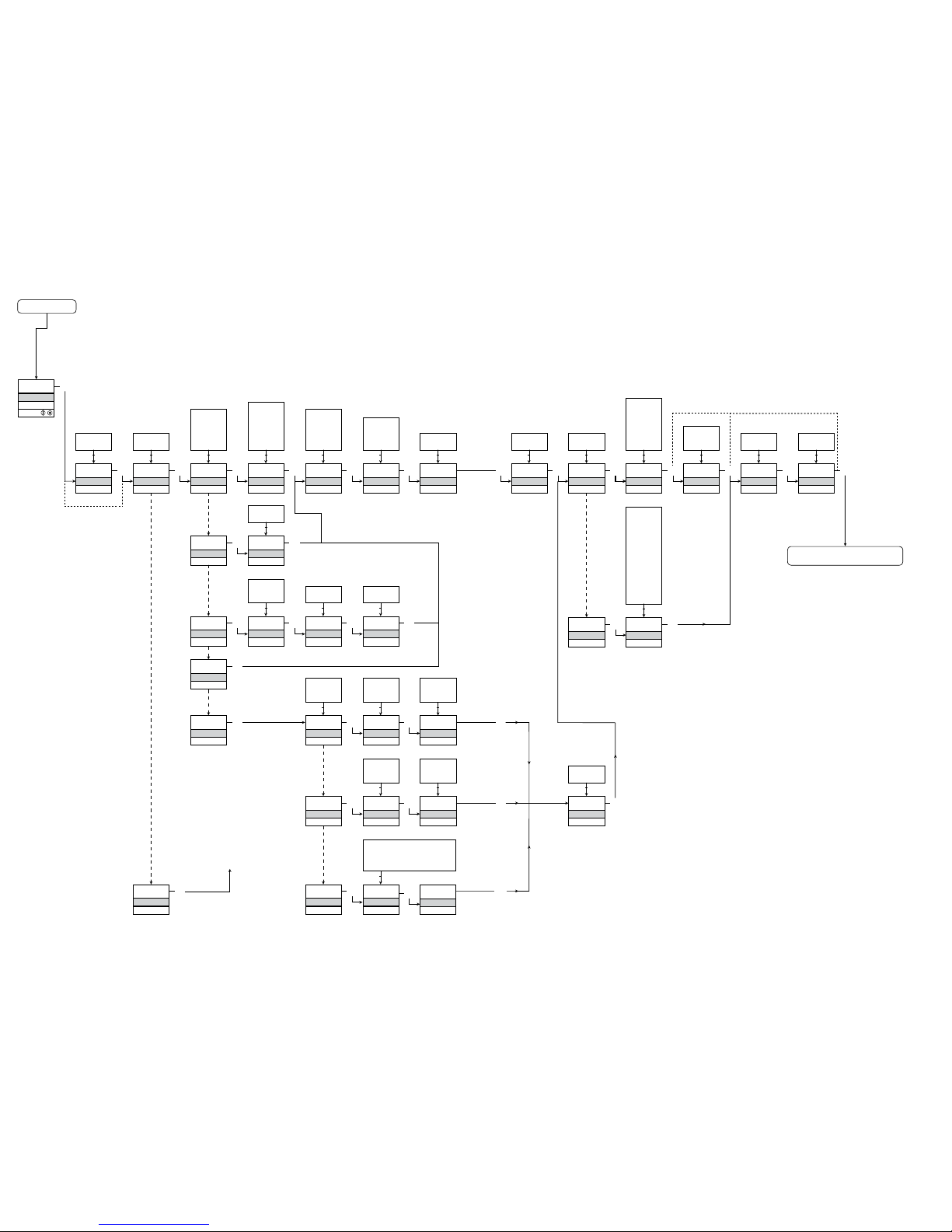
Når du skal konfigurere 4114, bliver du guidet igennem samtlige parametre og
kan vælge netop de indstillinger, der passer til applikationen. Til hver menu
findes en rullende hjælpetekst, som vises i displaylinie 3.
Konfigurationen udføres ved hjælp af de 3 taster:
1 forøger talværdien eller vælger næste parameter
2formindsker talværdien eller vælger forrige parameter
3accepterer valget og går til næste menu
Når konfigurationen er gennemført, returneres til normaltilstand 1.0.
Tryk og hold
3 tasten nede for at gå til forrige menu eller normaltilstand (1.0)
uden at gemme de ændrede tal eller parametre.
Hvis ingen taster har været aktiveret i 1 minut, returnerer displayet til normal-
tilstand (1.0) uden at gemme de ændrede tal eller parametre.
Uddybende forklaringer:
Passwordbeskyttelse: Programmeringsadgang kan forhindres ved indkodning
af et password. Passwordet gemmes i transmitteren, så sikkerheden mod
uønskede ændringer er så høj som muligt. Default password 2008 giver
adgang til alle programmeringsmenuer.
Signal- og følerfejlsinformation via displayfront 4501
Følerfejl (se grænser i skema) vises i display med SE.BR (sensor break) eller
SE.SH (sensor short). Signaler uden for det valgte område (ikke følerfejl, se
skema for grænser) vises i display som IN.LO (lavt indgangssignal) eller IN.HI
(højt indgangssignal). Fejlindikeringen vises i 3. linie i tekst, samtidig med at
baggrundsbelysningen blinker. 4. linie i displayet er en statuslinie, der viser
COM (blinkende bullet), som indikerer, om 4501 fungerer korrekt, og pil op/ned
der er tendensvisning på indgangssignalet.
Gnd.
*Bestilles særskilt: CJC-klemme 5910.
Page 11

18
19
Signal- og følerfejlsindikering uden displayfront
Status på enheden kan også aflæses på den røde/grønne LED i fronten af modulet.
Grøn blinkende LED 13 Hz indikerer normal drift.
Grøn blinkende LED 1 Hz indikerer følerfejl.
Konstant grøn LED indikerer intern fejl.
Konstant rød LED indikerer fatal fejl.
Avancerede funktioner
Enheden giver adgang til en række avancerede funktioner, der nås ved at svare
”yes” til punktet” adv.set”.
Display setup: Her kan man justere kontrast og baggrundsbelysning.
Opsætning af TAG-nummer med 6 alfanumeriske karakterer. Valg af funktionsvisning i linie 3 på displayet, der vælges mellem visning af analog
udgang og visning af TAG-nummer.
2-punkts proceskalibrering: Enheden kan proceskalibreres til et aktuelt ind-
gangssignal i 2 punkter. Der påtrykkes et lavt indgangssignal (ikke nødvendigvis 0%), og den aktuelle værdi angives på 4501. Herefter påtrykkes et
højt signal (ikke nødvendigvis 100%), og den aktuelle værdi angives på 4501.
Såfremt man siger ja til at bruge kalibreringen, vil enheden herefter arbejde i
henhold til denne nye justering. Siger man senere nej i dette punkt eller vælger en anden indgangssignaltype, går enheden tilbage til fabrikskalibreringen.
Processimulerings-funktion: Vælger man ja til punktet ”EN.SIM”, er det muligt
med piltasterne at simulere et indgangssignal og dermed styre udgangssignalet op og ned. Når man afslutter punktet med 3, går enheden tilbage til
normal mode igen.
Password: Her kan vælges et password mellem 0000 og 9999 til beskyttelse mod uautoriserede ændringer. Enheden leveres default uden password.
Såfremt man er kommet til at låse enheden med et password, man derefter
har glemt, kan man altid åbne menuen med password 2008.
Sprog: Der kan i menuen ”lang.setup” vælges mellem 7 forskellige sprogvarian-
ter af hjælpetekster der fremkommer i menuen. Der kan vælges mellem UK,
DE, FR, IT, ES, SE og DK.
Autodiagnosticering
Enheden foretager en avanceret autodiagnosticering af det interne kredsløb.
Følgende fejlmuligheder kan vises via displayfronten 4501.
CJ.ER – CJC-føler defekt eller CJC-temperatur uden for område
FL.ER – Fejl i Flash
AO.ER – Strømudgangen er ubelastet (gælder kun for S4...20 mA/S20...4 mA)
NO.CO – Fejl i stikforbindelserne
IN.ER – Fejlniveauer på indgang
TY.ER – Konfigurationen i 4501 stemmer ikke overens med denne produkttype
Valg af units
Efter valg af indgangssignaltype kan man vælge, hvilke procesenheder der skal
vises i displayet (se skema). Ved valg af temperaturindgang vises procesværdien altid i Celsius eller Fahrenheit. Vælges i menupunktet efter valg af
temperaturindgang.
Loop-overvågning
Når enheden er sat op til default, er SIL-funktionen slået fra. Det er muligt at
vælge loop-overvågning (safety readback) i menuen O.RANGE og derved slå
SIL-funktionen til på enheden. For at slå SIL-funktionen til skal man vælge
S4...20 mA. Man skal dog være opmærksom på, at når loop-overvågning er
valgt, vil man ikke få vist, at der er følerfejl, men i stedet få en meddelelse om
at der er fejl på det analoge udgangssignal.
CJC
Det er via menuen CJC muligt at vælge mellem ekstern CJC-klemme, og intern
CJC-kompensering. Ved TC via CJC-klemme bestilles særskilt: 5910 CJCklemme.
Memory
I memory menuen er det muligt at gemme opsætningen fra enheden i 4501, for
derefter at flytte 4501 over på en anden enhed af samme type og uploade
opsætningen til denne.
Page 12
Power up
0000
PASSW.
Txt 1
50.0
%
12.0
3
3
0000
9999
1 2
NO
ADV.SET
Txt 2
NO
YES
1 2
3
VOLT
IN TYPE
Txt 3
VOLT
CURR
LIN.R
POTM
TEMP
1 2
3
2-10
V.RANGE
Txt 4
2-10
0-10
1-5
0-5
0.2-1
0-1
1 2
3
CURR
IN TYPE
Txt 3
3
4-20
I.RANGE
Txt 5
0-20
4-20
1 2
3
LIN.R
IN TYPE
Txt 3
3
3W
CONNEC.
Txt 6
4W
3W
2W
1 2
3
POTM
IN TYPE
Txt 3
3
TEMP
IN TYPE
Txt 3
0
R 0%
Txt 7
0000
9999
1 2
3
2500
R 100%
Txt 8
0000
9999
1 2
3
Pt
SENSOR
Txt 10
Pt
NI
TC
1 2
3
YES
ADV.SET
Txt 2
3
Ni
SENSOR
Txt 10
3
TC
SENSOR
Txt 10
3
100
Pt TYPE
Txt 16
1000
-
10
1 2
3
3W
CONNEC.
Txt 6
4W
3W
2W
1 2
100
Ni TYPE
Txt 17
1000
-
50
1 2
3
3W
CONNEC.
Txt 6
4W
3W
2W
1 2
TC.K
TC.TYPE
Txt 18
TC.B TC.E TC.J TC.K
TC.L TC.N TC.R TC.S
TC.T TC.U TC.W3 TC.W5
TC.Lr
1 2
0.0
DISP.LO
Txt 13
999.9
-199.9
1 2
3
111.1
DEC.P
Txt 12
1111
111.1
11.11
1.111
1 2
3
UNIT
%
Txt 11
@C
mA
rpm
(69 units)
1 2
3
100.0
DISP.HI
Txt 14
999.9
-199.9
1 2
3 3
1.1
CURR
ANA.OUT
Txt 36
VOLT
CURR
1 2
3
4-20
O.RANGE
Txt 37
S20-4
20-4
20-0
S4-20
4-20
0-20
1 2
3
Volt
ANA.OUT
Txt 36
3
0-10
O.RANGE
Txt 39
10-2
10-0
5-1
5-0
1-0.2
1-0
2-10
0-10
1-5
0-5
0.2-1
0-1
1 2
3
23mA
OUT.ERR
Txt 38
23mA
0/3.5mA
NONE
1 2
3
0.0
OUT.LO
Txt 41
4172
-328
1 2
3
150.0
OUT.HI
Txt 42
4172
-328
1 2
1.2
1.3 1.3
3
1.0
3
3
3
@C
UNIT
Txt 9
@C
@F
1 2
3
3
@C
@F
%
A
bar
cm
ft
ft/h
ft/min
ft/s
g
gal/h
gal/min
GW
hp
hPa
Hz
in
in/h
in/min
in/s
ips
K
kA
kg
kJ
kPa
kV
kW
kWh
l
l/h
l/min
l/s
m
m/h
m/min
m/s
m/s2
m3
m3/h
m3/min
mA
mbar
mils
min
mm
mm/s
mol
MPa
mV
MW
MWh
N
Ohm
Pa
pH
rpm
s
S
t
t/h
uA
um
uS
V
W
Wh
yd
[blank]
3
INT
CJC
Txt 63
20
21
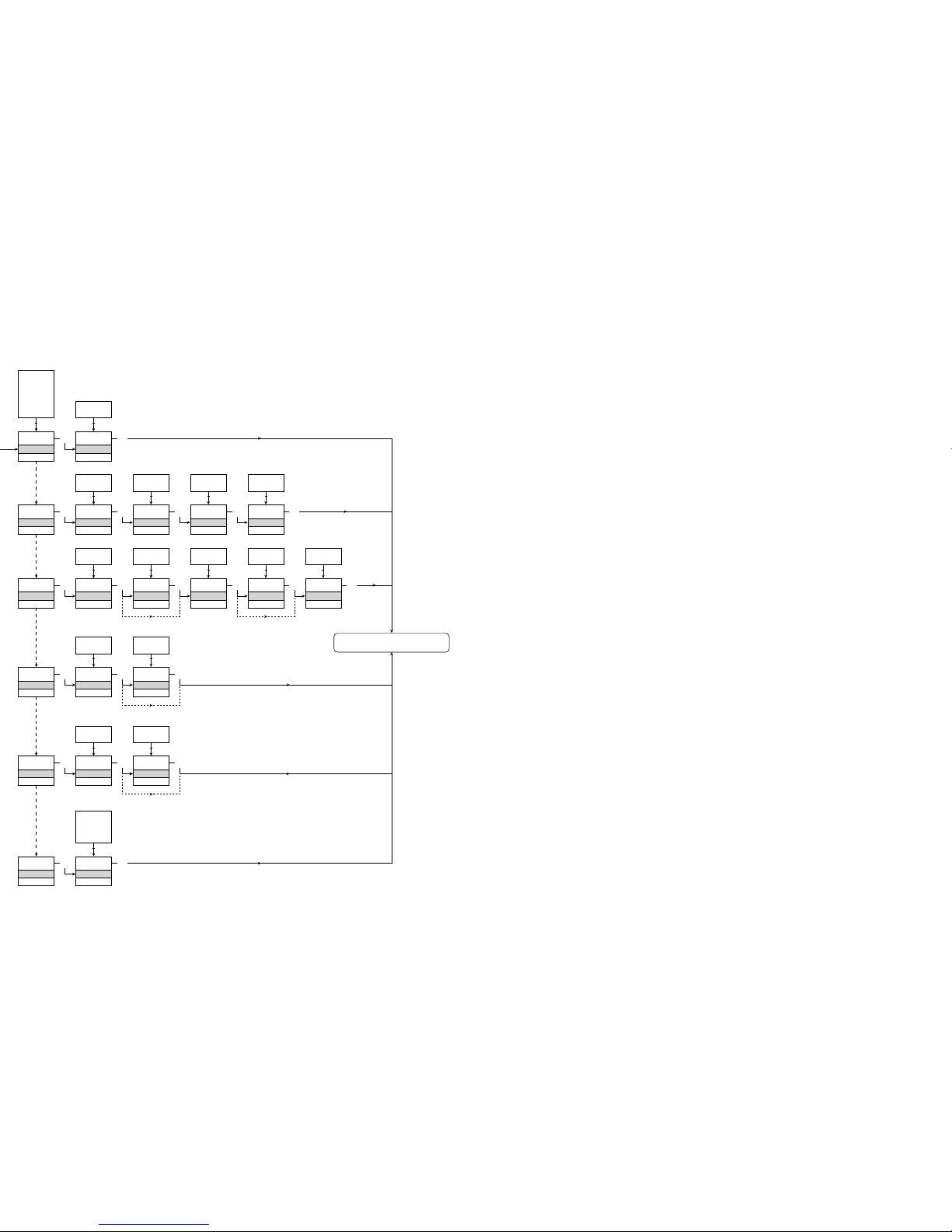
1.0 = Normaltilstand
Linie 1 viser ind gangssignal.
Linie 2 viser en heder - UNIT.
Ved at holde 1 og
2 samtidig skifter
visning i linie 3
mellem A.Out og
TAG.
Linie 4 viser status
for kommunikation.
1.1 = Kun hvis beskyttet
med password.
1.2 = Gælder ikke for
indgangssignaler:
0...20 mA og
spænding.
1.3 = Kun hvis indgangs signaler er tempe ratur.
Rutediagram
Hvis ingen taster har været aktiveret i 1 minut, returnerer displayet til normaltilstanden 1.0 uden at gemme eventuelle konfigurationsændringer.
1 Forøgelse af værdi / vælg næste parameter
2 Formindskelse af værdi / vælg forrige parameter
3 Accepter valget og gå til næste menu
Holde 3 går til forrige menu / returnerer til 1.0 uden at gemme
Fortsættes på siden
Rutediagram ADV.SET
Til normaltilstand 1.0
Valgbare UNIT:
Page 13
SAVE
MEMORY
Txt 44
3
SAVE
LOAD
1 2
MEM
SETUP
Txt 43
MEM
DISP
CAL
SIM
PASS
LANG
1 2
3
DISP
SETUP
Txt 43
3
3
CONTRA
Txt 45
3
9
0
1 2
9
LIGHT
Txt 46
3
9
0
1 2
VALVE 5
Txt 47
3
9
A
1 2
A.OUT
LINE 3
Txt 48
3
TAG
A.OUT
1 2
CAL
SETUP
Txt 43
3
YES
CAL.LO
Txt 49
3
YES
NO
1 2
2.0
%
Txt 61
3
100.0
0.0
1 2
NO
YES
CAL.HI
Txt 50
3
YES
NO
1 2
90.0
%
Txt 62
3
100.0
0.0
1 2
NO
YES
USE.CAL
Txt 60
3
YES
NO
1 2
SIM
SETUP
Txt 43
3
YES
EN.SIM
Txt 51
3
YES
NO
1 2
25.0
%
Txt 52
3
100.0
0.0
1 2
NO
PASS
SETUP
Txt 43
3 3
YES
EN.PASS
Txt 54
3
YES
NO
1 2
0000
NEW.PAS
Txt 55
3
9999
0000
1 2
LANG
SETUP
Txt 43
3
UK
LANGUA
Txt 59
3
DE, DK,
ES, FR,
IT, SE,
UK
1 2
2.0
NO
22
23
Rutediagram
avancerede indstillinger (ADV.SET)
Til normaltilstand 1.0
[01]
[02]
[03]
[04]
[05]
[06]
[07]
[08]
[09]
[10]
[11]
[12]
[13]
[14]
[16]
[17]
[18]
[36]
[37]
[38]
[39]
[41]
[42]
[43]
[44]
[45]
[46]
[47]
[48]
[49]
[50]
[51]
[52]
[54]
[55]
[59]
[60]
[61]
[62]
[63]
Angiv korrekt password
Gå til avanceret opsætningsmenu?
Vælg temperaturindgang
Vælg potentiometerindgang
Vælg lineær modstandsindgang
Vælg strømindgang
Vælg spændingsindgang
Vælg 0.0-1 V indgangsområde
Vælg 0.2-1 V indgangsområde
Vælg 0-5 V indgangsområde
Vælg 1-5 V indgangsområde
Vælg 0-10 V indgangsområde
Vælg 2-10 V indgangsområde
Vælg 0-20 mA indgangsområde
Vælg 4-20 mA indgangsområde
Vælg 2-leder følertilslutning
Vælg 3-leder følertilslutning
Vælg 4-leder følertilslutning
Indstil modstandsværdi lav
Indstil modstandsværdi høj
Vælg Celsius som temperaturenhed
Vælg Fahrenheit som temperaturenhed
Vælg TC-følertype
Vælg Ni-følertype
Vælg Pt-følertype
Vælg displayenheder
Vælg kommaplacering
Indstil displayområde lav
Indstil displayområde høj
Vælg Pt10 som følertype
Vælg Pt20 som følertype
Vælg Pt50 som følertype
Vælg Pt100 som følertype
Vælg Pt200 som følertype
Vælg Pt250 som følertype
Vælg Pt300 som følertype
Vælg Pt400 som følertype
Vælg Pt500 som følertype
Vælg Pt1000 som følertype
Vælg Ni50 som følertype
Vælg Ni100 som følertype
Vælg Ni120 som følertype
Vælg Ni1000 som følertype
Vælg TC-B som følertype
Vælg TC-E som følertype
Vælg TC-J som følertype
Vælg TC-K som følertype
Vælg TC-L som følertype
Vælg TC-N som følertype
Vælg TC-R som følertype
Vælg TC-S som følertype
Vælg TC-T som følertype
Vælg TC-U som følertype
Vælg TC-W3 som følertype
Vælg TC-W5 som følertype
Vælg TC-LR som følertype
Vælg strøm som analog udgangstype
Vælg spænding som analog udgangstype
Vælg 0-20 mA udgangsområde
Vælg 4-20 mA udgangsområde
Vælg S4-20 mA udgangsområde med loop overvågning
Vælg 20-0 mA udgangsområde
Vælg 20-4 mA udgangsområde
Vælg S20-4 mA udgangsområde med loop overvågning
Rullende hjælpetekster i displaylinie 3
Vælg ingen fejlaktion - udgang udefineret ved fejl
Vælg downscale ved fejl
Vælg NAMUR NE43 downscale ved fejl
Vælg NAMUR NE43 upscale ved fejl
Vælg 0.0-1 V udgangsområde
Vælg 0.2-1 V udgangsområde
Vælg 0-5 V udgangsområde
Vælg 1-5 V udgangsområde
Vælg 0-10 V udgangsområde
Vælg 2-10 V udgangsområde
Vælg 1-0.0 V udgangsområde
Vælg 1-0.2 V udgangsområde
Vælg 5-0 V udgangsområde
Vælg 5-1 V udgangsområde
Vælg 10-0 V udgangsområde
Vælg 10-2 V udgangsområde
Indstil temperatur for analog udgang lav
Indstil temperatur for analog udgang høj
Gå til password-indstilling
Gå til simuleringstilstand
Udfør proceskalibrering
Gå til displayopsætning
Udfør memory-operationer
Overfør gemt opsætning til 4114
Gem 4114-opsætning i 4501
Juster LCD-kontrast
Juster LCD-baggrundsbelysning
Angiv TAG-nr. - udfyld alle pladser
Analog udgangsværdi vises i displaylinie 3
TAG-nr. vises i displaylinie 3
Kalibrer indgang lav til procesværdi?
Kalibrer indgang høj til procesværdi?
Tillad simuleringstilstand?
Indstil simuleringsværdi for indgang
Tillad passwordbeskyttelse?
Angiv nyt password
Vælg sprog
Brug proceskalibreringsværdier?
Indstil værdi for lavt kalibreringspunkt
Indstil værdi for højt kalibreringspunkt
Vælg CJC-klemme (tilbehør)
Vælg intern CJC temperatursensor
2.0 I undermenuen simulering (SIM) skal 3 tryk kes for at returnere til normaltilstand 1.0
Page 14

24
25
UNIVERSAL TRANSMITTER
PReasy 4114
CONTENTS
Warnings ............................................................................ 26
Safety instructions .............................................................. 27
Declaration of Conformity .................................................. 29
How to demount SYSTEM 4000 ........................................ 30
When front LED lights red / display shows AO.ER ............ 30
Advanced features ............................................................. 31
Application ......................................................................... 31
Technical characteristics .................................................... 31
PR 4501 Display / programming front ............................... 32
Applications ........................................................................ 33
Order codes ....................................................................... 34
Electrical specifications ...................................................... 34
Display readout on 4501 of sensor error detection
and input signal outside range ....................................... 37
Sensor error detection limits .............................................. 37
Error indications ................................................................. 37
Connections ....................................................................... 39
Block diagram .................................................................... 40
Configuration / operating the function keys ...................... 41
Routing diagram ................................................................. 44
Routing diagram, advanced settings (ADV.SET) ................ 46
Scrolling help text in display line 3 .................................... 47
Page 15
26
27
SYMBOL IDENTIFICATION
Triangle with an exclamation mark: Warning / demand.
Potentially lethal situations.
The CE mark proves the compliance of the device with
the essential requirements of the directives.
The double insulation symbol shows that the device
is protected by double or reinforced insulation.
SAFETY INSTRUCTIONS
DEFINITIONS:
Hazardous voltages have been defined as the ranges: 75 to 1500 Volt DC, and
50 to 1000 Volt AC.
Technicians are qualified persons educated or trained to mount, operate, and
also troubleshoot technically correct and in accordance with safety regulations.
Operators, being familiar with the contents of this manual, adjust and operate
the knobs or potentiometers during normal operation.
RECEIPT AND UNPACKING:
Unpack the module without damaging it. The packing should always follow the
module until this has been permanently mounted.
Check at the receipt of the module whether the type corresponds to the one
ordered.
ENVIRONMENT:
Avoid direct sunlight, dust, high temperatures, mechanical vibrations and shock,
as well as rain and heavy moisture. If necessary, heating in excess of the stated
limits for ambient temperatures should be avoided by way of ventilation.
All devices fall under Installation Category II, Pollution Degree 1, and Insulation
Class II.
MOUNTING:
Only technicians who are familiar with the technical terms, warnings, and
instruc tions in the manual and who are able to follow these should connect the
device.
Should there be any doubt as to the correct handling of the device, please
contact your local distributor or, alternatively,
WARNING!
This device is designed for connection to hazardous electric
voltages.
Ignoring this warning can result in severe personal injury or
mechanical damage.
To avoid the risk of electric shock and fire, the safety
instructions of this manual must be observed and the guidelines
fol lowed. The specifications must not be exceeded, and the
device must only be applied as described in the following.
Prior to the commissioning of the device, this manual must be
examined carefully.
Only qualified personnel (technicians) should install this device.
If the equipment is used in a manner not specified by the
manufacturer, the protection provided by the equipment may be
impaired.
WARNING
SYSTEM 4000 must be mounted on a DIN rail according to DIN
46277.
WARNING!
Until the device is fixed, do not connect hazardous voltages to
the device.
The following operations should only be carried out on a
disconnected device and under ESD safe conditions:
General mounting, connection and disconnection of wires.
Troubleshooting the device.
Repair of the device and replacement of circuit breakers
must be done by PR electronics A/S only.
HAZARD-
OUS
VOLTAGE
INSTAL-
LATION
GENERAL
WARNING
Do not open the front plate of the module as this will cause
damage to the connector for the display / programming front
PR 4501. This module contains no DIP-switches or jumpers.
Page 16

28
29
DECLARATION OF CONFORMITY
As manufacturer
PR electronics A/S
Lerbakken 10
DK-8410 Rønde
hereby declares that the following product:
Type: 4114
Name: Universal transmitter
is in conformity with the following directives and standards:
The EMC Directive 2004/108/EC and later amendments
EN 61326-1
For specification of the acceptable EMC performance level, refer to the
electrical specifications for the device.
The Low Voltage Directive 2006/95/EC and later amendments
EN 61010-1
Rønde, 20 August 2009 Kim Rasmussen
Manufacturer’s signature
PR electronics A/S, Lerbakken 10, DK-8410 Rønde, Denmark,
tel: +45 86 37 26 77.
Mounting and connection of the device should comply with national legislation
for mounting of electric materials, i.e. wire cross section, protective fuse, and
location. Descriptions of input / output and supply connections are shown in
the block diagram and side label.
The following apply to fixed hazardous voltages-connected devices:
The max. size of the protective fuse is 10 A and, together with a power
switch, it should be easily accessible and close to the device. The power
switch should be marked with a label indicating that it will switch off the
volt age to the device.
Year of manufacture can be taken from the first two digits in the serial number.
UL INSTALLATION REQUIREMENTS:
Use 60/75°C copper conducters only
For use only in pollution degree 2 or better
Max. ambient temperature ..................... 60°C
Max. wire size ......................................... AWG 26-14
UL file number ........................................ E231911
CALIBRATION AND ADJUSTMENT:
During calibration and adjustment, the measuring and connection of external
voltages must be carried out according to the specifications of this manual. The
technician must use tools and instruments that are safe to use.
NORMAL OPERATION:
Operators are only allowed to adjust and operate devices that are safely fixed
in panels, etc., thus avoiding the danger of personal injury and damage. This
means there is no electrical shock hazard, and the device is easily accessible.
CLEANING:
When disconnected, the device may be cleaned with a cloth moistened with
distilled water.
LIABILITY:
To the extent that the instructions in this manual are not strictly observed, the
custom er cannot advance a demand against PR electronics A/S that would
otherwise exist according to the concluded sales agreement.
Page 17
30
31
UNIVERSAL TRANSMITTER
PReasy 4114
• Input for RTD, TC, Ohm, potentiometer, mA and V
• 2-wire supply > 16 V
• FM-approved for installation in Div. 2
• Output for current and voltage
• Universal AC or DC supply
Advanced features:
• Programmable by way of detachable display front (4501), process calibration,
signal simulation, password protection, error diagnostics and help text
available in several languages.
Application:
• Linearised, electronic temperature measurement with RTD or TC sensor.
• Conversion of linear resistance variation to a standard analogue current /
voltage signal, i.e. from solenoids and butterfly valves or linear movements
with attached potentio meter.
• Power supply and signal isolator for 2-wire transmitters.
• Process control with standard analogue output.
• Galvanic separation of analogue signals and measurement of floating signals.
• The 4114 is designed according to strict safety requirements and is thus
suitable for application in SIL 2 installations.
Technical characteristics:
• When 4114 is used in combination with the 4501 display / programming front,
all operational parameters can be modified to suit any application. As the
4114 is designed with electronic hardware switches, it is not necessary to
open the device for setting of DIP-switches.
• A green / red front LED indicates normal operation and malfunction.
• Continuous check of vital stored data for safety reasons.
• 3-port 2.3 kVAC galvanic isolation.
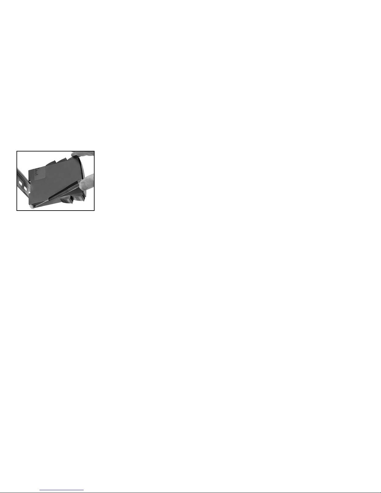
HOW TO DEMOUNT SYSTEM 4000
First, remember to demount the connectors with hazardous voltages.
Picture 1:
Detach the device from the DIN rail
by lifting the bottom lock.
When front LED lights red / display shows AO.ER:
PR 4114 is designed as a SIL 2 device with a high safety level. Therefore, a
continuous measurement of the outgoing current is carried out on a 4...20
mA output signal. If the current is 0, an error mode switches on the red front
LED. This function is not a default option but must be actively selected in the
menu. The error mode can only be reset by switching off and then switching
on the supply voltage to the device.
Page 18
+
-
+
-
44
43
42
41
12
14
13
11
+
-
10 V
1 V
+
-
10 V
1 V
33
32
31
*
32
33
PR 4501 DISPLAY / PROGRAMMING FRONT
Functionality:
The simple and easily understandable PReasy menu
structure and the explanatory help texts guide you
effortless ly and automatically through the configuration
steps, thus making the product very easy to use.
Functions and configuration options are described in the
section ”Configuration /
operating the function keys”.
Application:
• Communications interface for modification of operational parameters in 4114.
• Can be moved from one 4114 device to another and download the
configuration of the first transmitter to subsequent transmitters.
• Fixed display for readout of process data and status.
Technical characteristics:
• LCD display with 4 lines; Line 1 (H=5.57 mm) shows input signal, line 2
(H=3.33 mm) shows units, line 3 (H=3.33 mm) shows analogue output or tag
no. and line 4 shows communication status.
• Programming access can be blocked by assigning a password. The
password is saved in the transmitter in order to ensure a high degree of
protection against unauthorised modifications to the configuration.
Mounting / installation:
• Click 4501 onto the front of 4114.
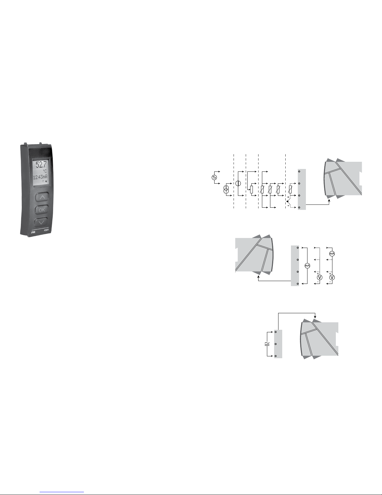
APPLICATIONS
Input signals:
Current
Volt
age
Potenti-
ometer
RTD and lin. R TC
Connect., wires
Output signals:
Supply:
21.6...253 VAC
or
19.2...300 VDC
Analogue, 0/4...20 mA and voltage
Order separately: 5910 CJC connector.
See the connection drawing on page 39.
Page 19
34
35
Auxiliary supplies:
2-wire supply (terminal 44...43) ................... 25...16 VDC / 0...20 mA
Max. wire size .............................................. 1 x 2.5 mm
2
stranded wire
Screw terminal torque ................................. 0.5 Nm
Relative humidity ......................................... < 95% RH (non-cond.)
Dimensions, without display front (HxBxD) .. 109 x 23.5 x 104 mm
Dimensions, with display front (HxBxD) ...... 109 x 23.5 x 116 mm
Protection degree ........................................ IP20
Weight ......................................................... 145 g / 160 g with 4501
RTD, linear resistance and potentiometer input:
Input for RTD types:
Pt10, Pt20, Pt50, Pt100, Pt200, Pt250, Pt300, Pt400, Pt500, Pt1000
Ni50, Ni100, Ni120, Ni1000
Cable resistance per wire (max.), RTD ........ 50 Ω
Sensor current, RTD .................................... Nom. 0.2 mA
Effect of sensor cable resistance
(3- / 4-wire), RTD ......................................... < 0.002 Ω / Ω
Sensor error detection, RTD ....................... Yes
Short circuit detection, RTD ........................ < 15 Ω
Order codes:
4114 = Universal transmitter
4501 = Display / programming front
5910 = CJC connector
Electrical specifications:
Specifications range .................................... -20°C to +60°C
Common specifications:
Supply voltage, universal ............................ 21.6...253 VAC, 50...60 Hz or
19.2...300 VDC
Max. consumption....................................... ≤ 2.0 W
Fuse ............................................................. 400 mA SB / 250 VAC
Isolation voltage, test / operation ............... 2.3 kVAC / 250 VAC
Communications interface .......................... Programming front 4501
Signal / noise ratio ...................................... Min. 60 dB (0...100 kHz)
Response time (0...90%, 100...10%):
Temperature input ................................... ≤ 1 s
mA / V input ............................................ ≤ 400 ms
Calibration temperature............................... 20...28°C
Accuracy, the greater of the general and basic values:
EMC immunity influence ..................................... < ±0.5% of span
Extended EMC immunity:
NAMUR NE 21, A criterion, burst ....................... < ±1% of span
Input
type
Min.
value
Max.
value
Standard
Pt100
Ni100
Lin. R
Potentiometer
-200°C
-60°C
0 Ω
10 Ω
+850°C
+250°C
10000 Ω
100 kΩ
IEC60751
DIN 43760
-
-
General values
Input
type
Absolute
accuracy
Temperature
coefficient
All ≤ ±0.1% of span ≤ ±0.01% of span / °C
Basic values
Input
type
Basic
accuracy
Temperature
coefficient
mA ≤ ±4 µA ≤ ±0.4 µA / °C
Volt ≤ ±20 µV ≤ ±2 µV / °C
Pt100 ≤ ±0.2°C ≤ ±0.01°C / °C
Linear resistance ≤ ±0.1 Ω ≤ ±0.01 Ω / °C
Potentiometer ≤ ±0.1 Ω ≤ ±0.01 Ω / °C
TC type:
E, J, K, L, N, T, U
≤ ±1°C
≤ ±0.05°C / °C
TC type: R, S, W3,
W5, LR
≤ ±2°C
≤ ±0.2°C / °C
TC type: B
160...400°C
≤ ±4.5°C
≤ ±0.45°C / °C
TC type: B
400...1820°C
≤ ±2°C
≤ ±0.2°C / °C
Page 20

36
37
Load (max.) .................................................. 20 mA / 800 Ω / 16 VDC
Load stability ............................................... ≤ 0.01% of span / 100 Ω
Sensor error detection ................................ 0 / 3.5 / 23 mA / none
NAMUR NE 43 Upscale / Downscale ......... 23 mA / 3.5 mA
Output limitation:
on 4...20 and 20...4 mA signals .............. 3.8...20.5 mA
on 0...20 and 20...0 mA signals .............. 0...20.5 mA
Current limit ................................................. ≤ 28 mA
Voltage output:
Signal range ................................................ 0...10 VDC
Programmable signal ranges ...................... 0...1 / 0.2...1 / 0...10 / 0...5 / 1...5 /
2...10 / 1...0 / 1...0.2 / 5...0 / 5...1 /
10...0 og 10...2 V
Load (min.) ................................................... 500 kΩ
Ex / I.S. approval:
FM, applicable in ......................................... Class I, Div. 2, Group A, B, C, D
Class I, Div. 2, Group IIC
Zone 2
Max. ambient temperature for T5 ............... 60°C
Marine approval:
Det Norske Veritas, Ships & Offshore ......... Standard for Certification No. 2.4
GOST R approval:
VNIIM, Cert. no. ........................................... See www.prelectronics.com
Observed authority requirements: Standard:
EMC 2004/108/EC ...................................... EN 61326-1
LVD 2006/95/EC .......................................... EN 61010-1
FM ............................................................... 3600, 3611, 3810 and ISA 82.02.01
UL, Standard for Safety .............................. UL 508
of span = of the currently selected measurement range
Display readout on the 4501 of sensor error detection and
input signal outside range
TC input:
Cold junction compensation (CJC)
via external sensor in
connector 5910 ....................................... 20...28°C ≤ ±1°C
-20...20°C /
28...70°C ≤±2°C
via internal CJC sensor ........................... ±(2.0°C + 0.4°C * Δt)
Δt = internal temperature - ambient temperature
Sensor error detection, all TC types ........... Yes
Sensor error current:
when detecting ....................................... Nom. 2 µA
else .......................................................... 0 µA
Current input:
Measurement range .................................... 0...20 mA
Programmable measurement ranges .......... 0...20 and 4...20 mA
Input resistance ........................................... Nom. 20 Ω + PTC 50 Ω
Sensor error detection:
Loop break 4...20 mA.............................. Yes
Voltage input:
Measurement range .................................... 0...12 VDC
Programmable measurement ranges .......... 0...1 / 0.2...1 / 0...5 / 1...5 /
0...10 and 2...10 VDC
Input resistance ........................................... Nom. 10 MΩ
Current output:
Signal range (span) ...................................... 0...20 mA
Programmable signal ranges ...................... 0...20 / 4...20 / 20...0 / 20...4 mA
Type
Min.
value
Max.
value
Standard
B
E
J
K
L
N
R
S
T
U
W3
W5
LR
0°C
-100°C
-100°C
-180°C
-200°C
-180°C
-50°C
-50°C
-200°C
-200°C
0°C
0°C
-200°C
+1820°C
+1000°C
+1200°C
+1372°C
+900°C
+1300°C
+1760°C
+1760°C
+400°C
+600°C
+2300°C
+2300°C
+800°C
IEC 60584-1
IEC 60584-1
IEC 60584-1
IEC 60584-1
DIN 43710
IEC 60584-1
IEC 60584-1
IEC 60584-1
IEC 60584-1
DIN 43710
ASTM E988-90
ASTM E988-90
GOST 3044-84
Sensor error check:
Device: Configuration Sensor error detection:
4114
OUT.ERR=NONE. OFF
Else: ON
Page 21
11 12 14
13
+
-
V
11 12 14
13
+
-
V
11 12 14
13
+
-
mA
+
-
41 42 44
43
41 42 44
43
42 44
43
41 41 42 44
43
41 42 44
43
+
-
41 42 44
43
+
-
41 42 44
43
+
-
Tx
41 42 44
43
31 32 33
41 42 44
43
+
-
41 42 44
CJC
38
39
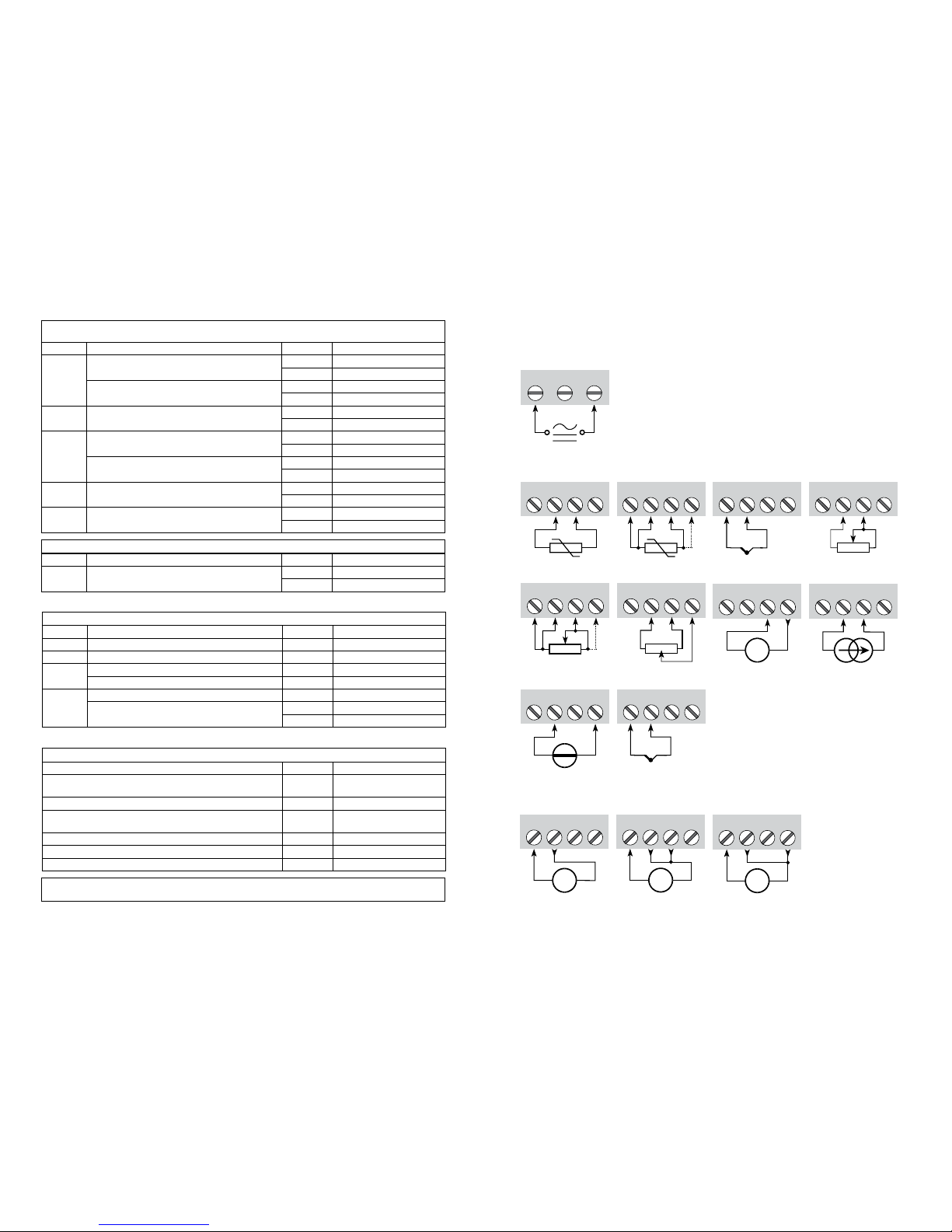
CONNECTIONS
Sensor error detection limits:
Error indications:
Outside range readout (IN.LO, IN.HI):
If the valid range of the A/D converter or the polynomial is exceeded
Input Range Readout Limit
VOLT
0...1 V / 0.2...1 V
IN.LO < -25 mV
IN.HI > 1.2 V
0...10 V / 2...10 V
IN.LO < -25 mV
IN.HI > 12 V
CURR 0...20 mA / 4...20 mA
IN.LO < -1.05 mA
IN.HI > 25.05 mA
LIN.R
0...800
Ω
IN.LO < 0 Ω
IN.HI > 1075 Ω
0...10 kΩ
IN.LO < 0 Ω
IN.HI < 110 kΩ
POTM -
IN.LO < -0.5 %
IN.HI > 100.5 %
TEMP TC / RTD
IN.LO < temperature range -2°C
IN.HI > temperature range +2°C
Sensor error detection (SE.BR, SE.SH):
Input Range Readout Limit
CURR Loop break (4..20 mA) SE.BR <= 3.6 mA; > = 21 mA
POTM All, SE.BR on all 3-wire SE.BR > ca. 126 k
Ω
LIN.R
0...800
Ω SE.BR > ca. 875 Ω
0...10 kΩ SE.BR > ca. 11 kΩ
TEMP
TC SE.BR > ca. 750 k
Ω / (1.25 V)
RTD, 2-, 3-, and 4-wire
No SE.SH for Pt10, Pt20 and Pt50
SE.BR > ca. 15 k
Ω
SE.SH < ca. 15 Ω
Display readout below min.- / above max. (-1999, 9999):
Input Range Readout Limit
All All
-1999 Display readout <-1999
9999 Display readout >9999
Readout at hardware error
Error search Readout Error cause
Test of internal CJC sensor CJ.ER
CJC sensor defect or tem-
perature outside range
Checksum test of the configuration in FLASH FL.ER Error in FLASH
Check measurement of analogue output current AO.ER
1) No load on the current output (only S4...20/S20...4 mA)
Communications test 4501 / 4114 NO.CO Connection error
Check that input signal matches input configuration IN.ER 1) Error levels on input
Check that saved configuration in 4501 matches device
TY.ER Configuration is not 4114
! Error indications in the display flash once per second. The help text explains the error.
1) The error is reset by switching off and then switching on the supply voltage to the device.
Inputs
Outputs
Supply:
Voltage, 1 V Voltage, 10 VCurrent
RTD, 3- / 4-wireRTD, 2-wire Resistance, 2-wire
Resistance,
3- / 4-wire
Potentiometer
Current2-wire transmitter
Voltage
*TC, external
CJC connector
* Order separately: CJC connector 5910
TC, internal
CJC sensor
Page 22
50.0
VALVE 5
l / min
4114
4
3
2
+
-
+
-
11
13
14
500Ω
50Ω
33
31
12
D / A
Safety
A / D
PTC
CJC
0.2 mA
43
44
42
41
10 Ω
MUX
EEPROM
CPU
VV
mA
mA
I+
10 V
1 V
+
-
*
40
41
CONFIGURATION /
OPERATING THE FUNCTION KEYS
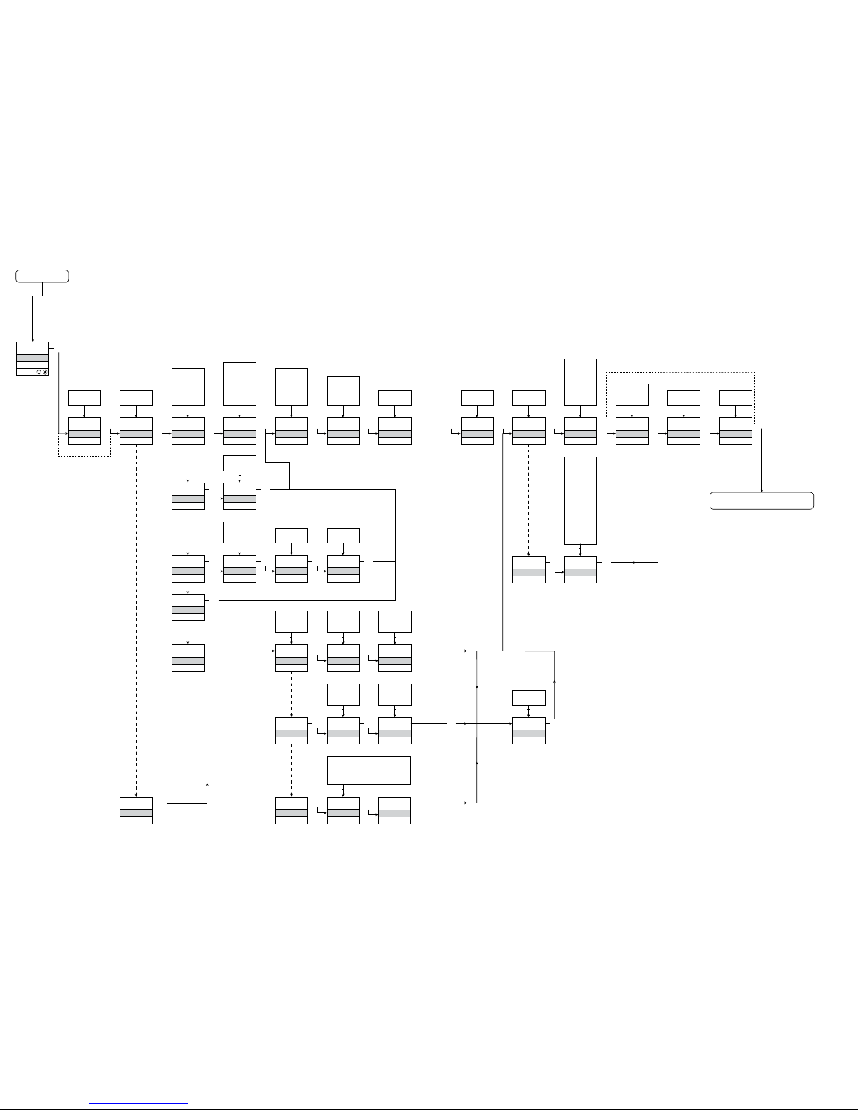
Documentation for routing diagram.
In general:
When configuring the 4114, you will be guided through all parameters and you
can choose the settings which fit the application. For each menu there is a
scrolling help text which is automatically shown in line 3 on the display.
Configuration is carried out by using the 3 function keys:
1 will increase the numerical value or choose the next parameter
2will decrease the numerical value or choose the previous parameter
3will accept the chosen value and proceed to the next menu
When configuration is completed, the dispaly will return to the default state 1.0.
Pressing and holding
3 will return to the previous menu or return to the default
state (1.0) without saving the changed values or parameters.
If no key is activated for 1 minute, the display will return to the default state
(1.0) without saving the changed values or parameters.
Further explanations:
Password protection: Programming access can be blocked by assigning a
password. The password is saved in the transmitter in order to ensure a high
degree of protection against unauthorised modifications to the configuration.
Default password 2008 allows acces to all configuration menus.
Signal and sensor error info via display front 4501
Sensor error (see limits in the table) is displayed as SE.BR (sensor break) or
SE.SH (sensor short). Signals outside the selected range (not sensor error,
see table for limits) are displayed as IN.LO indicating low input signal or
IN.HI indicating high input signal. The error indication is displayed in line 3
as text and at the same time the backlight flashes. Line 4 of the display is a
status line which displays COM (flashing bullet) indicating correct functioning
of 4501, and arrow up/down which indicates tendency readout of the input
signal.
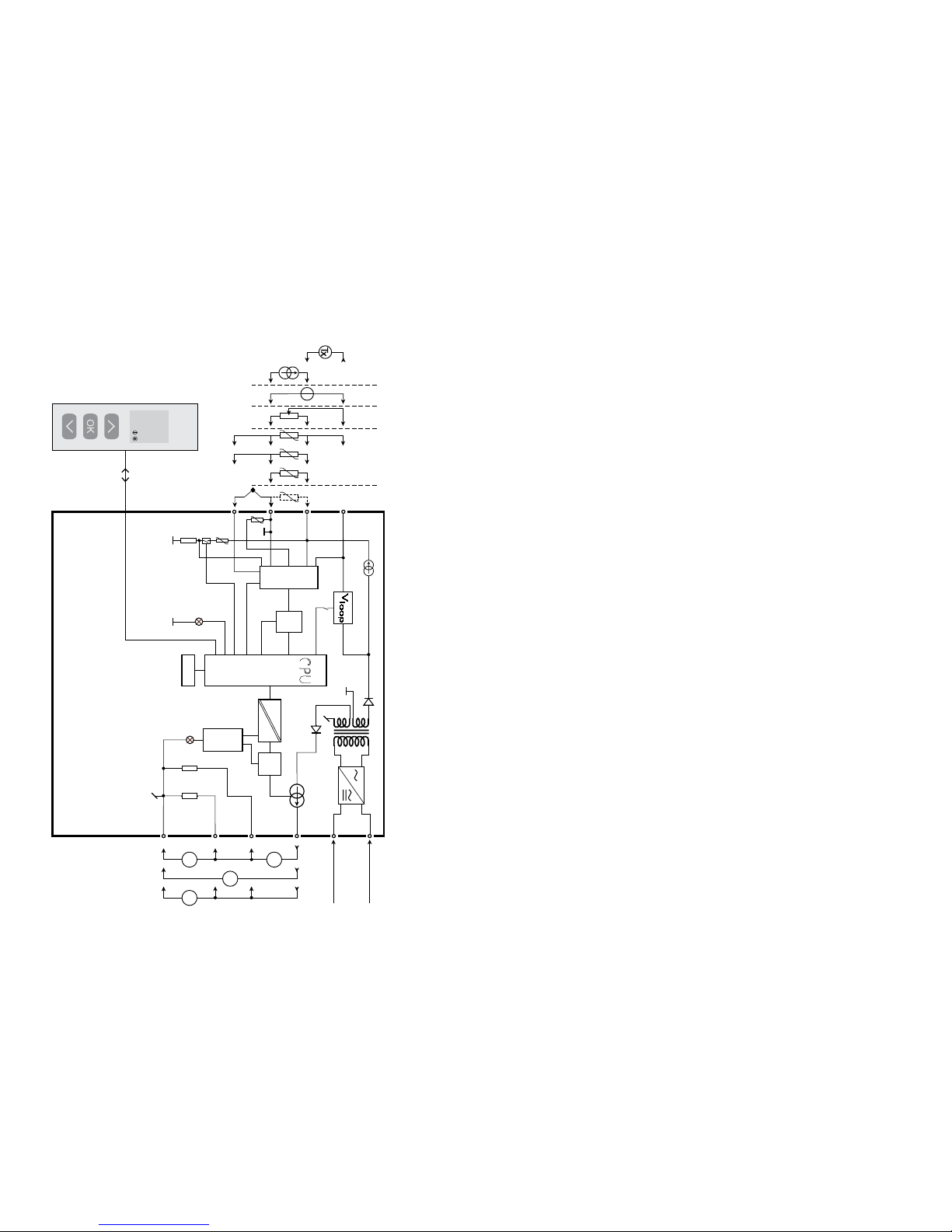
BLOCK DIAGRAM
Potentiometer
2-wire transmitter
Voltage
Current
RTD and lin. R,
connection,
wires
Supply
Supply
21.6...253 VAC or
19.2...300 VDC
Gnd.
I + V
Out.
I
Out.
V
Out.
TC
Green
Red
Order separately: CJC connector 5910
Page 23

42
43
Signal and sensor error indication without display front
Status of the unit can also be read from the red/green LED in the front of the device.
Green flashing LED 13 Hz indicates normal operation.
Green flashing LED 1 Hz indicates sensor error.
Steady green LED indicates internal error.
Steady red LED indicates fatal error.
Advanced functions
The unit gives access to a number of advanced functions which can be reached
by answering “Yes” to the point “adv.set”.
Display setup: Here you can adjust the brightness contrast and the backlight.
Setup of TAG number with 6 alphanumerics. Selection of functional readout
in line 3 of the display - choose between readout of analogue output or TAG
number.
Two-point process calibration: The unit can be process-calibrated in 2 points
to fit a given input signal. A low input signal (not necessarily 0%) is applied
and the actual value is entered via 4501. Then a high signal (not necessarily
100%) is applied and the actual value is entered via 4501. If you accept to
use the calibration, the unit will work according to this new adjustment. If you
later reject this menu point or choose another type of input signal the unit will
return to factory calibration.
Process simulation function: If you say ”yes” to the point “EN.SIM” it is
possible to simulate an input signal by means of the arrow keys and thus
control the output signal up or down. When you finalise the point with 3, the
unit returns to normal mode.
Password: Here you can choose a password between 0000 and 9999 in order
to protect the unit against unauthorised modifications to the configuration.
The unit is delivered default without password. If you have locked the unit
with a password by mistake, you can always open the menu by using the
master password 2008.
Language: In the menu ”lang.setup” you can choose between 7 different
language versions of help texts that will appear in the menu. You can choose
between UK, DE, FR, IT, ES, SE and DK.
Auto diagnosis
The unit performs an advanced auto diagnosis of the internal circuits.
The following possible errors can by display in the front unit 4501.
CJ.ER - CJC sensor defect or CJC temperature outside range
FL.ER - Flash error
AO.ER - No load on the current output (only for S4...20 mA/S20...4 mA)
NO.CO - Connection error
IN.ER - Error levels on input
TY.ER - Configuration in 4501 does not match this product type
Selection of units
After choosing the input signal type you can choose the process units which
will be displayed in text line 2 (see table). By selection of temperature input
the process value is always displayed in Celsius or Fahrenheit. This is
selected in the menu point after selection of temperature input.
Safety readback
When the device is delivered with default configuration, the SIL function is
disabled. The safety readback function (loop surveillance) can be selected in
the menu O.RANGE, thus enabling the device to run in SIL mode. In order
to enable the SIL functionality, the menu item S4...20 mA must be selected.
Please note, however, that when safety readback is enabled, a sensor error
will be indicated as an error on the analogue output signal.
CJC
In the CJC menu you can choose between external CJC connector and internal
cold junction compensation. The external CJC connector (PR 5910) must be
ordered separately.
Memory
In the memory menu you can save the configuration of the device in the 4501,
and then move the 4501 onto another device of the same type and download
the configuration in the new device.
Page 24
Power up
0000
PASSW.
Txt 1
50.0
%
12.0
3
3
0000
9999
1 2
NO
ADV.SET
Txt 2
NO
YES
1 2
3
VOLT
IN TYPE
Txt 3
VOLT
CURR
LIN.R
POTM
TEMP
1 2
3
2-10
V.RANGE
Txt 4
2-10
0-10
1-5
0-5
0.2-1
0-1
1 2
3
CURR
IN TYPE
Txt 3
3
4-20
I.RANGE
Txt 5
0-20
4-20
1 2
3
LIN.R
IN TYPE
Txt 3
3
3W
CONNEC.
Txt 6
4W
3W
2W
1 2
3
POTM
IN TYPE
Txt 3
3
TEMP
IN TYPE
Txt 3
0
R 0%
Txt 7
0000
9999
1 2
3
2500
R 100%
Txt 8
0000
9999
1 2
3
Pt
SENSOR
Txt 10
Pt
NI
TC
1 2
3
YES
ADV.SET
Txt 2
3
Ni
SENSOR
Txt 10
3
TC
SENSOR
Txt 10
3
100
Pt TYPE
Txt 16
1000
-
10
1 2
3
3W
CONNEC.
Txt 6
4W
3W
2W
1 2
100
Ni TYPE
Txt 17
1000
-
50
1 2
3
3W
CONNEC.
Txt 6
4W
3W
2W
1 2
TC.K
TC.TYPE
Txt 18
TC.B TC.E TC.J TC.K
TC.L TC.N TC.R TC.S
TC.T TC.U TC.W3 TC.W5
TC.Lr
1 2
0.0
DISP.LO
Txt 13
999.9
-199.9
1 2
3
111.1
DEC.P
Txt 12
1111
111.1
11.11
1.111
1 2
3
UNIT
%
Txt 11
@C
mA
rpm
(69 units)
1 2
3
100.0
DISP.HI
Txt 14
999.9
-199.9
1 2
3 3
1.1
CURR
ANA.OUT
Txt 36
VOLT
CURR
1 2
3
4-20
O.RANGE
Txt 37
3
Volt
ANA.OUT
Txt 36
3
0-10
O.RANGE
Txt 39
10-2
10-0
5-1
5-0
1-0.2
1-0
2-10
0-10
1-5
0-5
0.2-1
0-1
1 2
3
23mA
OUT.ERR
Txt 38
23mA
0/3.5mA
NONE
1 2
3
0.0
OUT.LO
Txt 41
4172
-328
1 2
3
150.0
OUT.HI
Txt 42
4172
-328
1 2
1.2
1.3 1.3
3
1.0
3
3
@C
UNIT
Txt 9
@C
@F
1 2
3
@C
@F
%
A
bar
cm
ft
ft/h
ft/min
ft/s
g
gal/h
gal/min
GW
hp
hPa
Hz
in
in/h
in/min
in/s
ips
K
kA
kg
kJ
kPa
kV
kW
kWh
l
l/h
l/min
l/s
m
m/h
m/min
m/s
m/s2
m3
m3/h
m3/min
mA
mbar
mils
min
mm
mm/s
mol
MPa
mV
MW
MWh
N
Ohm
Pa
pH
rpm
s
S
t
t/h
uA
um
uS
V
W
Wh
yd
[blank]
S20-4
20-4
20-0
S4-20
4-20
0-20
1 2
3
INT
CJC
Txt 63
3
3
44
45
1.0 = Default state
Line 1 shows input
signal.
Line 2 shows
UNIT.
By pressing 1 and
2 simultaneously
line 3 alternates
between A.Out
and TAG.
Line 4 shows com munication status.
1.1 = Only if password protected.
1.2 = Not valid for these
input signals:
0...20 mA and
voltage.
1.3 = Only if input signal
is temperaure.
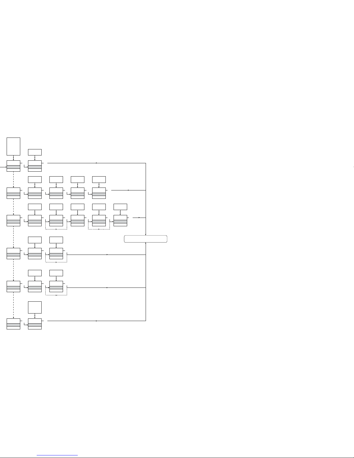
Routing diagram
If no key is activated for 1 minute, the display will return to the default
state 1.0 without saving configuration changes.
1 Increase value / choose next parameter
2 Decrease value / choose previous parameter
3 Accept the chosen value and proceed to the next menu
Hold 3 Back to previous menu / return to menu 1.0 without saving
Continued on the page
Routing diagram ADV.SET
To default state 1.0
Selectable UNITS:
Page 25
SAVE
MEMORY
Txt 44
3
SAVE
LOAD
1 2
MEM
SETUP
Txt 43
MEM
DISP
CAL
SIM
PASS
LANG
1 2
3
DISP
SETUP
Txt 43
3
3
CONTRA
Txt 45
3
9
0
1 2
9
LIGHT
Txt 46
3
9
0
1 2
VALVE 5
Txt 47
3
9
A
1 2
A.OUT
LINE 3
Txt 48
3
TAG
A.OUT
1 2
CAL
SETUP
Txt 43
3
YES
CAL.LO
Txt 49
3
YES
NO
1 2
2.0
%
Txt 61
3
100.0
0.0
1 2
NO
YES
CAL.HI
Txt 50
3
YES
NO
1 2
90.0
%
Txt 62
3
100.0
0.0
1 2
NO
YES
USE.CAL
Txt 60
3
YES
NO
1 2
SIM
SETUP
Txt 43
3
YES
EN.SIM
Txt 51
3
YES
NO
1 2
25.0
%
Txt 52
3
100.0
0.0
1 2
NO
PASS
SETUP
Txt 43
3 3
YES
EN.PASS
Txt 54
3
YES
NO
1 2
0000
NEW.PAS
Txt 55
3
9999
0000
1 2
LANG
SETUP
Txt 43
3
UK
LANGUA
Txt 59
3
DE, DK,
ES, FR,
IT, SE,
UK
1 2
2.0
NO
46
47
Routing diagram
Advanced settings (ADV.SET)
To default state 1.0
[01]
[02]
[03]
[04]
[05]
[06]
[07]
[08]
[09]
[10]
[11]
[12]
[13]
[14]
[16]
[17]
[18]
[36]
[37]
[38]
[39]
[41]
[42]
[43]
[44]
[45]
[46]
[47]
[48]
[49]
[50]
[51]
[52]
[54]
[55]
[59]
[60]
[61]
[62]
[63]
Set correct password
Enter advanced setup menu?
Select temperature input
Select potentiometer input
Select linear resistance input
Select current input
Select voltage input
Select 0.0-1 V input range
Select 0.2-1 V input range
Select 0-5 V input range
Select 1-5 V input range
Select 0-10 V input range
Select 2-10 V input range
Select 0-20 mA input range
Select 4-20 mA input range
Select 2-wire sensor connection
Select 3-wire sensor connection
Select 4-wire sensor connection
Set resistance value low
Set resistance value high
Select Celsius as temperature unit
Select Fahrenheit as temperature unit
Select TC sensor type
Select Ni sensor type
Select Pt sensor type
Select display unit
Select decimal point position
Set display range low
Set display range high
Select Pt10 as sensor type
Select Pt20 as sensor type
Select Pt50 as sensor type
Select Pt100 as sensor type
Select Pt200 as sensor type
Select Pt250 as sensor type
Select Pt300 as sensor type
Select Pt400 as sensor type
Select Pt500 as sensor type
Select Pt1000 as sensor type
Select Ni50 as sensor type
Select Ni100 as sensor type
Select Ni120 as sensor type
Select Ni1000 as sensor type
Select TC-B as sensor type
Select TC-E as sensor type
Select TC-J as sensor type
Select TC-K as sensor type
Select TC-L as sensor type
Select TC-N as sensor type
Select TC-R as sensor type
Select TC-S as sensor type
Select TC-T as sensor type
Select TC-U as sensor type
Select TC-W3 as sensor type
Select TC-W5 as sensor type
Select TC-Lr as sensor type
Select current as analogue output type
Select voltage as analogue output type
Select 0-20 mA output range
Select 4-20 mA output range
Select S4-20 mA with safety readback
Select 20-0 mA output range
Select 20-4 mA output range
Select S20-4 mA with safety readback
Scrolling help text in display line 3
Select no error action - output undefined at error
Select downscale at error
Select NAMUR NE43 downscale at error
Select NAMUR NE43 upscale at error
Select 0.0-1 V output range
Select 0.2-1 V output range
Select 0-5 V output range
Select 1-5 V output range
Select 0-10 V output range
Select 2-10 V output range
Select 1-0.0 V output range
Select 1-0.2 V output range
Select 5-0 V output range
Select 5-1 V output range
Select 10-0 V output range
Select 10-2 V output range
Set temperature for analogue output low
Set temperature for analogue output high
Enter password setup
Enter simulation mode
Perform process calibration
Enter display setup
Perform memory operations
Load saved configuration into 4114
Save 4114 configuration in 4501
Adjust LCD contrast
Adjust LCD backlight
Write a 6-character device TAG
Analogue output value is shown in display line 3
Device TAG is shown in display line 3
Calibrate input low to process value?
Calibrate input high to process value?
Enable simulation mode?
Set the input simulation value
Enable password protection?
Set new password
Select language
Use process calibration values?
Set value for low calibration point
Set value for high calibration point
Select CJC connector (accessory)
Select internal temperature sensor
2.0 In the submenu simulation (SIM) you must
press 3 to return to the default state 1.0.
Page 26

48
49
TRANSMETTEUR UNIVERSEL
PReasy 4114
SOMMAIRE
Avertissements ................................................................... 50
Consignes de sécurité ....................................................... 51
Déclaration de conformité .................................................. 53
Démontage du SYSTEME 4000 ......................................... 54
Quand la DEL rouge s’allume / l’indicateur affiche AO.ER .. 54
Options avancées............................................................... 55
Fonctions ............................................................................ 55
Caractéristiques techniques............................................... 55
PR 4501 Indicateur / façade de programmation ............... 56
Applications ........................................................................ 57
Références de commande ................................................. 58
Spécifications électriques .................................................. 58
Indication dans le 4501 de la détection erreur capteur
et du signal d’entrée hors d’échelle ............................... 61
Limites de la détection erreur capteur ............................... 62
Indications erreurs matériels .............................................. 62
Connexions ........................................................................ 63
Schéma de principe ........................................................... 64
Configuration / utilisation des touches de fonction ........... 65
Diagramme de programmation .......................................... 68
Diagramme de programmation,
réglage avancé (ADV.SET) .............................................. 70
Le menu déroulant en ligne 3 de l’indicateur..................... 71
Page 27
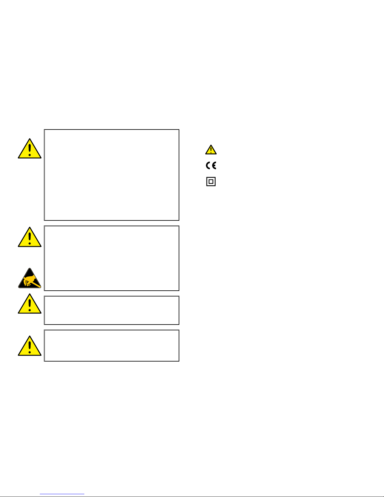
50
51
SIGNIFICATION DES SYMBOLES
Triangle avec point d’exclamation : Attention ! Si vous ne
respectez pas les instructions, la situation pourrait être fatale.
Le signe CE indique que le module est conforme aux exigences des
directives.
Ce symbole indique que le module est protégé par une isolation double
ou renforcée.
CONSIGNES DE SECURITE
DEFINITIONS
Les gammes de tensions dangereuses sont les suivantes : de 75 à 1500 Vcc et de
50 à 1000 Vca. Les techniciens sont des person nes qualifiées qui sont capables
de monter et de faire fonc tionner un appareil, et d’y rechercher les pannes, tout
en respectant les règles de sécurité. Les opérateurs, connaissant le contenu de
ce guide, règlent et actionnent les boutons ou les potentiomètres au cours des
manipulations ordinaires.
RECEPTION ET DEBALLAGE
Déballez le module sans l’endommager. Il est recommandé de conserver
l’emballage du module tant que ce dernier n’est pas définitivement monté. A la
réception du module, vérifiez que le type de module reçu correspond à celui que
vous avez commandé.
ENVIRONNEMENT
N’exposez pas votre module aux rayons directs du soleil et choisissez un
endroit à humidité modérée et à l’abri de la poussière, des températures
élevées, des chocs et des vibrations mécaniques et de la pluie. Le cas
échéant, des systèmes de ventilation permettent d’éviter qu’une pièce soit
chauffée au-delà des limites prescrites pour les températures ambiantes.
Tous les modules appartiennent à la catégorie d’installation Il, au degré de
pollution I et à la classe d’isolation Il.
MONTAGE
Il est conseillé de réserver le raccordement du module aux techniciens qui
connaissent les termes techniques, les avertis sements et les instructions de ce
guide et qui sont capables d’appliquer ces dernières.
Si vous avez un doute quelconque quant à la manipulation du module, veuillez
contacter votre distributeur local. Vous pouvez également vous adresser à :
AVERTISSEMENT !
Ce module est conçu pour supporter une connexion à des
tensions électriques dangereuses. Si vous ne tenez pas compte
de cet avertissement, cela peut causer des dommages corporels
ou des dégâts mécaniques.
Pour éviter les risques d’électrocution et d’incendie, conformezvous aux consignes de sécurité et suivez les instructions
mentionnées dans ce guide. Vous devez vous limiter aux
spécifications indiquées et respecter les instruc tions d’utilisation
de ce module, telles qu’elles sont décrites dans ce guide.
Il est nécessaire de lire ce guide attentivement avant de mettre
ce module en marche. L’installation de ce module est réservée à
un personnel qualifié (techniciens). Si la méthode d’utilisation de
l’équipement diffère de celle décrite par le fabricant, la protection
assurée par l’équipe ment risque d’être altérée.
AVERTISSEMENT !
Il convient de monter l’appareil SYSTEM 4000 sur un rail DIN en
se conformant à la norme DIN 46277.
AVERTISSEMENT !
Tant que le module n’est pas fixé, ne le mettez par sous
tensions dangereuses. Les opérations suivantes doivent être
effec tuées avec le module débranché et dans un environnement
exempt de décharges électrostatiques (ESD) : montage général,
raccordement et débranchement de fils et recherche de pannes
sur le module.
Seule PR electronics SARL est autorisée à réparer le module
et à remplacer les fusibles.
TENSION
DANGE-
REUSE
INSTAL-
LATION
INFORMA-
TIONS
GENERALES
AVERTISSEMENT !
Ne pas ouvrir la plaque avant du module au risque
d’endommager le connecteur de l’indicateur / la façade de
programmation PR 4501. Ce module ne contient ni de
commutateurs DIP ni de cavaliers.
Page 28

52
53
DECLARATION DE CONFORMITE
En tant que fabricant
PR electronics A/S
Lerbakken 10
DK-8410 Rønde
déclare que le produit suivant :
Type : 4114
Nom : Transmetteur universel
correspond aux directives et normes suivantes :
La directive CEM (EMC) 2004/108/CE et les modifications subséquentes
EN 61326-1
Pour une spécification du niveau de rendement acceptable CEM (EMC)
se référer aux spécifications électriques du module.
La directive basse tension 2006/95/CE et les modifications subséquentes
EN 61010-1
Rønde, 20 août 2009 Kim Rasmussen
Signature du fabricant
PR electronics SARL, Zac du Chêne, Activillage, 4, allée des Sorbiers, F-69673
Bron Cedex (tél. : (0) 472 140 607) ou à PR electronics A/S, Lerbakken 10, DK8410 Rønde, Danemark (tél. : +45 86 37 26 77).
Le montage et le raccordement du module doivent être conformes à la législation
nationale en vigueur pour le montage de matéri aux électriques, par ex emple,
diamètres des fils, fusibles de protection et implantation des modules. Les
connexions des alimentations et des entrées / sorties sont décrites dans
le schéma de principe et sur l’étiquette de la face latérale du module. Les
instructions suivantes s’appliquent aux modules fixes connectés en tensions
dangereu ses :
Le fusible de protection doit être de 10 A au maximum. Ce dernier,
ainsi que l’interrupteur général, doivent être facilement accessibles et à
proximité du module. Il est recommandé de placer sur l’interupteur général
une étiquette indiquant que ce dernier mettra le module hors tension.
CONDITIONS D’INSTALLATION UL :
N’utilisez que de conducteurs de cuivre 60/75°C
Uniquement pour utilisation en degré de pollution 2 ou meilleur
Température ambiente max.................................... 60°C
Taille max. des fils, borne 41...46........................... AWG 26-14
No du fichier UL ..................................................... E231911
ETALONNAGE ET REGLAGE
Lors des opérations d’étalonnage et de réglage, il convient d’effectuer les
mesures et les connexions des tensions externes en respectant les spécifica tions
mentionnées dans ce guide. Les techniciens doivent utiliser des outils et des
instruments pouvant être manipulés en toute sécurité.
MANIPULATIONS ORDINAIRES
Les opérateurs sont uniquement autorisés à régler et faire fonctionner des
modules qui sont solidement fixés sur des platines des tableaux, ect., afin
d’écarter les risques de dommages corporels. Autrement dit, il ne doit exister
aucun danger d’électrocution et le module doit être facilement accessible.
MAINTENANCE ET ENTRETIEN
Une fois le module hors tension, prenez un chiffon imbibé d’eau distillée pour
le nettoyer.
LIMITATION DE RESPONSABILITE
Dans la mesure où les instructions de ce guide ne sont pas strictement
respectées par le client, ce dernier n’est pas en droit de faire une réclamation
auprès de PR electronics SARL, même si cette dernière figure dans l’accord de
vente conclu.
Page 29
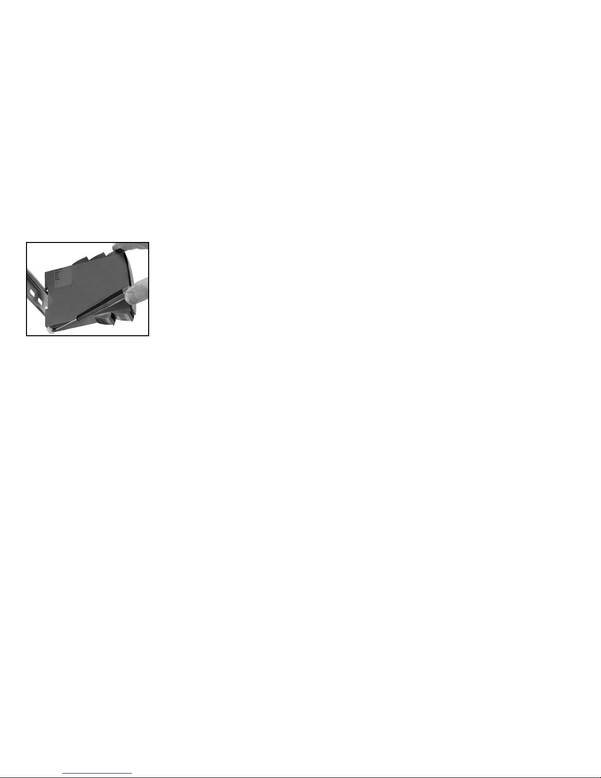
54
55
TRANSMETTEUR UNIVERSEL
PReasy 4114
• Entrées : RTD, TC, mV, Ohm, potentiomètre, mA et V
• Alimentation 2-fils > 16 V
• Approbation FM pour installation en Div. 2
• Sorties : courant et tension
• Alimentation multi-tension ca ou cc
Options avancées :
• Programmable à l’aide de la façade de programmation (4501), calibration de
process, simulation de signaux, protection par mot de passe, diagnostic
d’erreurs et textes d’aide disponibles en plusieurs langues.
Fonctions :
• Mesure électronique linéarisée de la température avec un capteur RTD ou un
thermocouple.
• Conversion d’une variation de la résistance linéaire en un signal courant ou
tension analogique. Signal potentiométrique en provenance de vannes, vannes
papillons ou mouvement linéaire.
• Alimentation et isolateur de signaux pour transmetteurs 2-fils.
• Contrôle de procédés avec sortie analogique standard.
• Isolataion galvanique de signaux analogiques et mesure de signaux flottants.
• Le 4114 a été construit avec un niveau de sécurité élevé permettant de
l’utiliser dans les installations classées SIL 2.
Caractéristiques techniques :
• Quand l’indicateur / façade de programmation 4501 est monté, tous les
paramètres de fonctionnement peuvent être réglés quelle que soit l’application.
Le module est équipé de commutateurs électroniques et ne nécessite donc
aucun réglage de commutateurs DIP.
• La DEL verte / rouge en face avant indique un fonctionnement normal ou
incorrect du module.
• Vérification continue des données sauvegardées.
• Isolation galvanique 3-port de 2,3 kVca.
DEMONTAGE DU SYSTEME 4000
Tout d’abord, n’oubliez pas de démonter les connecteurs où règnent des
ten sions dangereuses.
Figure 1 :
Débloquez le verrou inférieur pour
dégager le module du rail DIN.
Quand la DEL rouge s’allume / l’indicateur affiche AO.ER :
PR4114 est conçu pour répondre aux éxigences d’un niveau de sécurité SIL2.
De ce fait une mesure continue de la boucle de courant de sortie 4...20 mA
est faite. Si le courant est à 0, un mode de detection d’erreur commute la DEL
rouge. Cette fonction ne peut être validée que par la programmation. La remise
à zero de ce défaut se fait en coupant l’alimentation.
Page 30
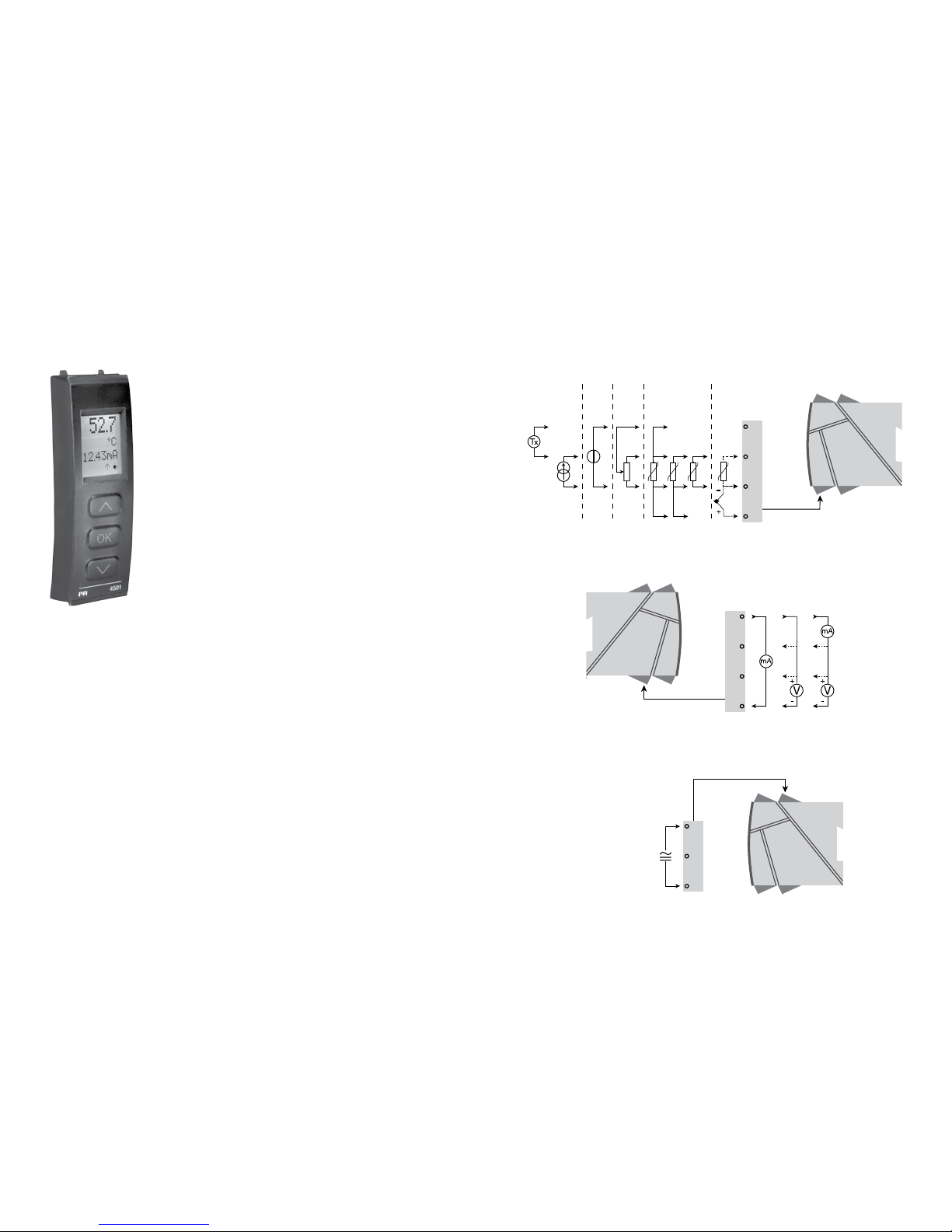
+
-
+
-
44
43
42
41
12
14
13
11
+
-
10 V
1 V
+
-
10 V
1 V
33
32
31
*
56
57
PR 4501 INDICATEUR /
FAÇADE DE PROGRAMMATION
Fonctionnalité :
Le menu simple, structuré à l’aide de questions pour
la configuration du PReasy guide automatiquement
l’utilisateur par un menu déroulant et rend ainsi aisé
l’utilisation du produit. Voir la description des fonctions et
options de configuration dans la section « Configuration /
utilisation des touches de fonction ».
Application :
• Interface de communication pour la modification des paramètres de
fonctionnement du 4114.
• Peut être transféré d’un 4114 à un autre 4114 et charger la configuration du
premier transmetteur vers les transmetteurs suivants.
• Comme indicateur fixe pour visualisation des données de process et de l’état.
Caractéristiques techniques :
• Ligne 1 (5,57 mm de haut) affiche le signal d’entrée, ligne 2 (3,33 mm de
haut) affiche les unités, ligne 3 (3,33 mm de haut) affiche la sortie analogique
ou le numéro de repère et ligne 4 affiche l’etat de communication.
• L’accès à la programmation peut être bloquée par un mot de passe. Ce mot
de passe est sauvegardé dans le transmetteur afin d’assurer un haut niveau
de protection contre les modifications non autorisées.
Montage / installation:
• Cliquer le 4501 sur la face avant du 4114.
APPLICATIONS
Signaux d’entrée :
Courant
Tension
Poten-
tio mètre
RTD et R lin. TC
Connexion, fils
Signaux de sortie :
Alimentation :
21,6...253 Vca
ou
19,2...300 Vcc
Analogique, 0/4...20 mA et tension
*Commander separément :
Connecteur CSF 5910
Page 31
58
59
Tensions auxiliaires :
Alimentation 2-fils (borne 44...43) ............... 25...16 Vcc / 0...20 mA
Taille max. des fils ....................................... 1 x 2,5 mm
2
fils multibrins
Pression max. avant
déformation de la vis ................................... 0,5 Nm
Humidité relative.......................................... < 95% HR (sans cond.)
Dimensions, sans façade 4501 (HxLxP) ..... 109 x 23,5 x 104 mm
Dimensions, avec façade 4501 (HxLxP) ..... 109 x 23,5 x 116 mm
Degré de protection .................................... IP20
Poids ........................................................... 145 g / 160 g avec 4501
Entrée RTD, résistance linéaire et potentiomètre :
Entrée pour types RTD :
Pt10, Pt20, Pt50, Pt100, Pt200, Pt250, Pt300, Pt400, Pt500, Pt1000
Ni50, Ni100, Ni120, Ni1000
Résistance de ligne max. par fil, RTD ......... 50 Ω
Courant de capteur, RTD ............................ Nom. 0,2 mA
Effet de la résistance de ligne
3- / 4-fils, RTD ............................................. < 0,002 Ω / Ω
Détection de rupture capteur, RTD ............. Oui
Détection de court circuit, RTD ................... < 15 Ω
References de commande :
4114 = Transmetteur universel
4501 = Indicateur / façade de programmation
5910 = Connecteur CSF
Spécifications :
Plage de température .................................. -20°C à +60°C
Spécifications communes :
Tension d’alimentation universelle .............. 21,6...253 Vca, 50...60 Hz
ou 19,2...300 Vcc
Consommation max. ................................... ≤ 2,0 W
Fusible ......................................................... 400 mA SB / 250 Vca
Tension d’isolation, test / opération ............ 2,3 kVca / 250 Vca
Interface de communication ....................... Façade de programmation 4501
Rapport signal / bruit .................................. Min. 60 dB (0...100 kHz)
Temps de réponse (0...90%, 100...10%) :
Entrée température ................................. ≤ 1 s
Entrée mA / V .......................................... ≤ 400 ms
Température d’étalonnage .......................... 20...28°C
Précision, la plus grande des valeurs générales et de base :
Immunité CEM ..................................................... < ±0,5% de l’EC
Immunité CEM améliorée :
NAMUR NE 21, critère A, burst .......................... < ±1% de l’EC
Type
d’entrée
Valeur
min.
Valeur
max.
Standard
Pt100
Ni100
R lin.
Potentiomètre
-200°C
-60°C
0 Ω
10 Ω
+850°C
+250°C
10000 Ω
100 kΩ
IEC60751
DIN 43760
-
-
Valeurs générales
Type
d’entrée
Précision
absolue
Coefficient
de température
Toutes ≤ ±0,1% de l’EC ≤ ±0,01% de l’EC / °C
Valeurs de base
Type
d’entrée
Précision
de base
Coefficient
de température
mA ≤ ±4 µA ≤ ±0,4 µA / °C
Volt ≤ ±20 µV ≤ ±2 µV / °C
Pt100 ≤ ±0,2°C ≤ ±0,01°C / °C
Résistance linéaire ≤ ±0,1 Ω ≤ ±0,01 Ω / °C
Potentiomètre ≤ ±0,1 Ω ≤ ±0,01 Ω / °C
Type TC :
E, J, K, L, N, T, U
≤ ±1°C
≤ ±0,05°C / °C
Type TC : R, S,
W3, W5, LR
≤ ±2°C
≤ ±0,2°C / °C
Type TC : B
160...400°C
≤ ±4,5°C
≤ ±0,45°C / °C
Type TC : B
400...1820°C
≤ ±2°C
≤ ±0,2°C / °C
Page 32

60
61
Charge (max.) .............................................. 20 mA / 800 Ω / 16 Vcc
Stabilité de charge ...................................... ≤ 0,01% de l’EC / 100 Ω
Détection erreur capteur ............................. 0 / 3,5 / 23 mA / aucune
NAMUR NE 43 haut / bas d’échelle ........... 23 mA / 3,5 mA
Limite de sortie :
signal 4...20 et 20...4 mA ........................ 3,8...20,5 mA
signal 0...20 et 20...0 mA ........................ 0...20,5 mA
Limite de courant ........................................ ≤ 28 mA
Sortie tension :
Gamme de signal ........................................ 0...10 Vcc
Gammes de signal programmables ............ 0...1 / 0,2...1 / 0...10 / 0...5 / 1...5 /
2...10 / 1...0 / 1...0,2 / 5...0 / 5...1 /
10...0 og 10...2 V
Charge (min.) ............................................... 500 kΩ
Approbation Ex / S.I. :
FM, applicable en ........................................ Class I, Div. 2, Group A, B, C, D
Class I, Div. 2, Group IIC
Zone 2
Température amb. max. pour T5 ................. 60°C
Approbation marine :
Det Norske Veritas, Ships & Offshore ......... Standard for Certification No. 2.4
Approbation GOST R :
VNIIM, Cert. no. ........................................... Voir www.prelectronics.fr
Agréments et homologations : Standard :
CEM (EMC) 2004/108/CE : .......................... EN 61326-1
DBT 2006/95/CE ......................................... EN 61010-1
FM ............................................................... 3600, 3611, 3810 et ISA 82.02.01
UL, Standard for Safety .............................. UL 508
EC = échelle configurée
Indication dans le 4501 de la détection erreur capteur
et du signal d’entrée hors d’échelle :
Entrée TC :
Compensation de soudure froide (CSF) :
avec capteur externe monté
sur le bornier 5910 .................................. 20...28°C ≤ ± 1°C
-20...20°C /
28...70°C ≤ ± 2°C
avec capteur CFS interne ....................... ±(2,0°C + 0,4°C * Δt)
Δt = température interne-température ambiante
Détection de rupture capteur,
tous types de TC .....................................Oui
Courant de capteur :
pendant la détection ............................... Nom. 2 µA
si non ....................................................... 0 µA
Entrée courant :
Gamme de mesure ...................................... 0...20 mA
Gammes de mesure programmables.......... 0...20 et 4...20 mA
Résistance d’entrée .................................... Nom. 20 Ω + PTC 50 Ω
Détection d'erreur capteur:
interruption de la boucle 4...20 mA......... Oui
Entrée tension :
Gamme de mesure ...................................... 0...12 Vcc
Gammes de mesure programmables.......... 0...1 / 0,2...1 / 0...5 / 1...5 /
0...10 et 2...10 Vcc
Résistance d’entrée .................................... Nom. 10 MΩ
Sortie courant :
Gamme de signal (EC) ................................ 0...20 mA
Gammes de signal programmables ............ 0...20 / 4...20 / 20...0 / 20...4 mA
Type
Valeur
min.
Valeur
max.
Standard
B
E
J
K
L
N
R
S
T
U
W3
W5
LR
0°C
-100°C
-100°C
-180°C
-200°C
-180°C
-50°C
-50°C
-200°C
-200°C
0°C
0°C
-200°C
+1820°C
+1000°C
+1200°C
+1372°C
+900°C
+1300°C
+1760°C
+1760°C
+400°C
+600°C
+2300°C
+2300°C
+800°C
IEC 60584-1
IEC 60584-1
IEC 60584-1
IEC 60584-1
DIN 43710
IEC 60584-1
IEC 60584-1
IEC 60584-1
IEC 60584-1
DIN 43710
ASTM E988-90
ASTM E988-90
GOST 3044-84
Vérifications erreur capteur :
Module : Configuration Détection erreur capteur
4114
OUT.ERR=NONE. OFF
Autre : ON
Page 33
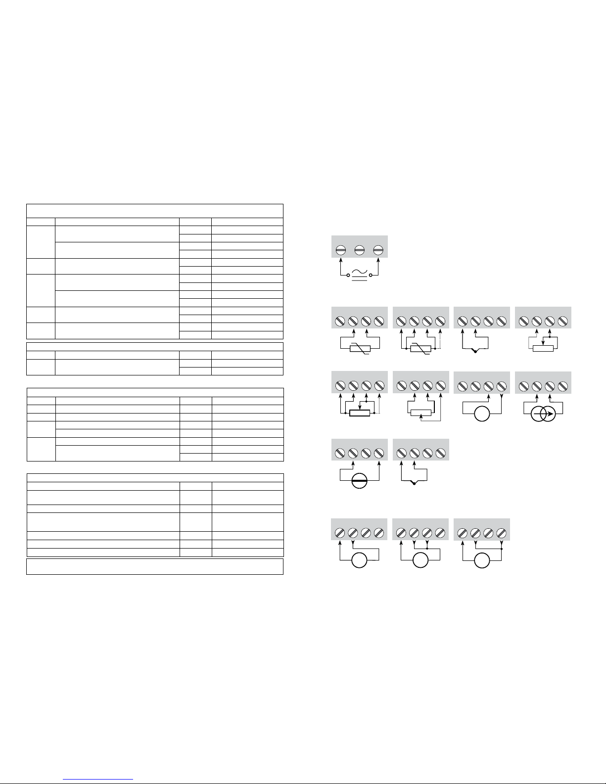
11 12 14
13
+
-
V
11 12 14
13
+
-
V
11 12 14
13
+
-
mA
+
-
41 42 44
43
41 42 44
43
42 44
43
41 41 42 44
43
41 42 44
43
+
-
41 42 44
43
+
-
41 42 44
43
+
-
Tx
41 42 44
43
31 32 33
41 42 44
43
+
-
41 42 44
CJC
62
63
Limites de la détection erreur capteur :
Indications erreurs matériels :
CONNEXIONS
Indication de dépassement d’échelle (IN.LO, IN.HI) :
En dépassement de l’echelle définie du convertisseur A/D ou des standards températures
Entrée Plage Affichage Limite
VOLT
0...1 V / 0,2...1 V
IN.LO < -25 mV
IN.HI > 1,2 V
0...10 V / 2...10 V
IN.LO < -25 mV
IN.HI > 12 V
CURR 0...20 mA / 4...20 mA
IN.LO < -1,05 mA
IN.HI > 25,05 mA
LIN.R
0...800
Ω
IN.LO < 0 Ω
IN.HI > 1075 Ω
0...10 kΩ
IN.LO < 0 Ω
IN.HI < 110 kΩ
POTM -
IN.LO < -0,5 %
IN.HI > 100,5 %
TEMP TC / RTD
IN.LO < plage de températ. -2°C
IN.HI > plage de températ. +2°C
Détection erreur capteur (SE.BR, SE.SH) :
Entrée Plage Affichage Limite
CURR Rupture de boucle (4..20 mA) SE.BR <= 3,6 mA; > = 21 mA
POTM Tous, SE.BR sur toutes connexions 3-fils SE.BR > env. 126 k
Ω
LIN.R
0...800
Ω SE.BR > env. 875 Ω
0...10 kΩ SE.BR > env. 11 kΩ
TEMP
TC SE.BR > env. 750 k
Ω / (1,25 V)
RTD, 2-, 3- et 4-fils
Pas de SE.SH pour Pt10, Pt20 et Pt50
SE.BR > env. 15 k
Ω
SE.SH < env. 15 Ω
Affichage en dessous du mini. / au-dessus du maxi (-1999, 9999) :
Entrée Plage Affichage Limite
Tous Tous
-1999 Indication <-1999
9999 Indication >9999
! Les indications d’erreurs clignotent toutes les secondes. Un texte d’aide explique l’erreur.
1) L’erreur est corrigée en déconnectant et puis reconnectant l’alimentation du module.
Entrées
Sorties
Alimentation :
Tension, 1 V Tension, 10 VCourant
RTD, 3- / 4-filsRTD, 2-fils Résistance, 2-fils
Résistance,
3- / 4-fils
Potentiomètre
CourantTransmetteur 2-fils
Tension
Indication erreur matériel
Recherche erreurs Affichage Cause d’erreur
Vérification du capteur CSF interne CJ.ER
Défaut capt. CSF ou temp.
en dépassement d’échelle
Vérification complète de la mémoire FLASH FL.ER Erreur dans la mém. FLASH
Vérification de la sortie analogique AO.ER
1) Sortie courant est sans
charge (uniq. S4...20 mA/
S20...4 mA)
Vérification de la communication entre 4501 / 4114 NO.CO Erreur de connexion
Vérif. que le signal d’entrée correspond à la config. d’entrée IN.ER 1) Niv. d’erreur à l’entrée
Vérific. si la config. gardée en 4501 correspond au module TY.ER Config. n’est pas 4114
TC, capteur
CSF interne
*TC,
connecteur CSF
* Commander separément :
connecteur CSF 5910
Page 34
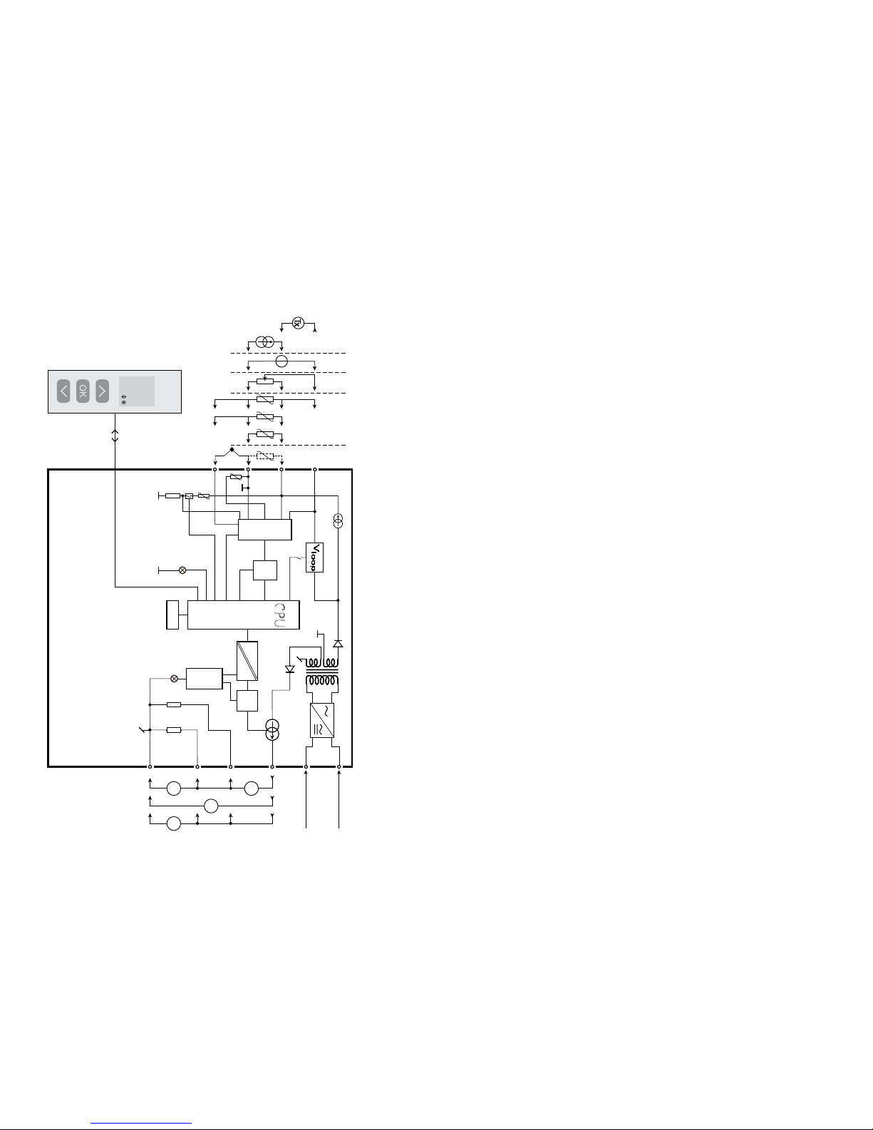
50.0
VALVE 5
l / min
4114
4
3
2
+
-
+
-
11
13
14
500Ω
50Ω
33
31
12
D / A
Safety
A / D
PTC
CJC
0.2 mA
43
44
42
41
10 Ω
MUX
EEPROM
CPU
VV
mA
mA
I+
10 V
1 V
+
-
*
64
65
PROGRAMMATION /
OPERATION DES TOUCHES DE FONCTION
Documentation pour le diagramme de programmation.
Généralités :
Lors de la configuration de l’indicateur vous êtes guidés tout au long des
paramètres du menu ; ainsi vous pouvez choisir le réglage qui correspond à
votre application. Pour chaque menu il y a un texte d’aide qui défile en ligne
3 de l’indicateur.
La configuration se fait à l’aide des 3 touches de fonction :
1 Incrémenter la valeur numérique ou choisir le paramètre suivant
2Décrémenter la valeur numérique ou choisir le paramètre précédent
3Valider les valeurs choisies et fin du menu
Une fois la configuration terminée, l’indicateur retournera sur l’état défaut 1.0.
En appuyant et maintenant la touche
3 l’indicateur retourne au menu
précédent ou sur l’état défaut (1.0) sans sauvegarde des modifications
éventuelles apportées à la configuration.
Si aucune touche n’est activée pendant 1 minute, l’indicateur retournera sur
l’état défau sans sauvegarde des modifications éventuelles apportées à la
configuration.
Information complémentaire :
Protection par mot de passe : L’accès à la programmation peut être bloqué
par un mot de passe. Ce mot de passe est sauvegardé dans le transmetteur
afin d’assurer un haut niveau de protection contre les modifications non
autorisées. Le mot de passe usine 2008 permet l’accès à tous les menus de
configuration.
Informations relatives au signal et erreur capteur sur la façade 4501
Erreur capteur (voir limites dans tableau) est affiché par SE.BR (rupture capteur)
ou SE.SH (court circuit). Signal hors limite (voir tableau des limites) est affiché
par IN.LO (limite basse) ou IN.HI (limite haute). L’affichage de l’erreur se fait
sur la ligne 3 en format texte avec le rétro-éclairage lumineux clignotant.
La ligne 4 de l’affichage indique COM (balle clignotante) qui indique l’état
de fonctionnement du 4501 et la flèche montante/descendante indique la
tendance du signal d’entrée.
SCHEMA DE PRINCIPE
Potentiomètre
Transmetteur 2-fils
Tension
Courant
RTD et R lin,
conexions,
fils
Alimentation
Alimentation
21,6...253 Vca ou
19,2...300 Vcc
Masse
I + V
Sort.
I
Sort.
V
Sort.
TC
Verte
Rouge
Commander separément : connecteur CSF 5910
Page 35

66
67
Indication du signal et erreur capteur sans la façade
L’état du module peut être lu sur la façade à l’aide des voyants rouge/vert.
Voyant vert clignotant à 13 Hz indique l’état normal de fonctionnement.
Voyant vert clignotant à 1 Hz indique l’erreur capteur.
Voyant vert fixe indique une erreur interne.
Voyant rouge fixe indique erreur fatale.
Fonctions avancées
L’unité donne accès à un certain nombre de fonctions avancées qui sont
accessibles en répondant « Oui » à « adv.set ».
Configuration de l’affichage : Il est possible de régler la luminosité et le
rétro-éclairage. Enregistrement d’un numéro de repère à 6 caractères
alphanumériques. Sélection de l’affichage de la valeur de sortie ou du repère
sur ligne 3 de l’indicateur.
Calibration du process en 2 points
: L’unité peut procéder à une calibration
en 2 points. Le point mini du signal d’entrée (pas nécessairement 0%) est
appliquée et la valeur actuelle est entrée sur le 4501. Ensuite le point maxi
du signal (pas nécessairement 100%) est appliquée et la valeur actuelle est
entrée sur le 4501. Si vous validez ces points, l’appareil va fonctionner selon
cet ajustement. Si plus tard vous souhaitez modifier ou changer de type
d’entrée l’unité reviendra à la calibration usine.
Fonction simulation : Si vous validez le point « EN.SIM » il est possible de
simuler un signal d’entrée à l’aide des flèches et ainsi contrôler le signal de
sortie haut et bas. Lorsque vous validez le point par 3, l’unité retourne à son
mode normal.
Mot de passe : Ici vous pouvez choisir un mot de passe allant de 0000 à 9999
afin de protéger la programmation. L’unité est livrée sans mot de passe. Si
par erreur vous verrouillez l’unité par un mot de passe, vous pouvez toujours
l’annuler par le mot de passe 2008.
Langue : Dans le menu « choix de la langue », vous pouvez sélectionner 7
différentes langues pour le texte d’aide. Choix entre : Anglais, allemand,
français, italien, espagnol, suédois et danois.
Auto-diagnostic
L’unité effectue la fonction auto-diagnostic des circuits internes.
Voici les erreurs possibles affichées sur l’unité 4501 :
CJ.ER - Défaut capteur CSF ou température CSF en dépassement d’échelle
FL.ER - Erreur flash
AO.ER - La sortie courant est sans charge (uniquement pour les signaux
S4...20 mA et S20...4 mA)
NO.CO - Erreur de connexion
IN.ER - Niveaux d’erreur à l’entrée
TY.ER - Configuration du 4501 différente du type de produit
Sélection des unités
Après avoir choisi le type de signal d’entrée, vous pouvez choisir l’unité
de valeur du process pour l’affichage en texte ligne 2 (voir tableau). En
sélectionnant une entrée température, l’unité de mesure sur l’afficheur est en
Celsius ou Fahrenheit.
Fonction securité
Par défaut les appareils sont livrés avec la fonction SIL inactive. La fonction
sécurité (surveillance de boucle) peut être selectionnée sur le menu O.RANGE
ce qui permet à la carte de fonctionner en mode SIL. De plus il faut que la
sortie S4...20mA soit validée. Veuillez noter que lorsque la fonction sécurité
est activée la fonction erreur capteur est signalée sur la sortie analogique.
CJC
Dans le menu CJC vous pouvez choisir une compensation interne ou externe
de la soudure froide. La compensation externe se fait par le bornier 5910, il
est à commander séparemment.
Mémoire
Dans le menu mémoire (memory) vous pouvez sauvegarder la configuration du
module dans le 4501, et puis transférer le 4501 sur un autre module du même
type et charger la configuration sauvegardée vers ce module.
Page 36
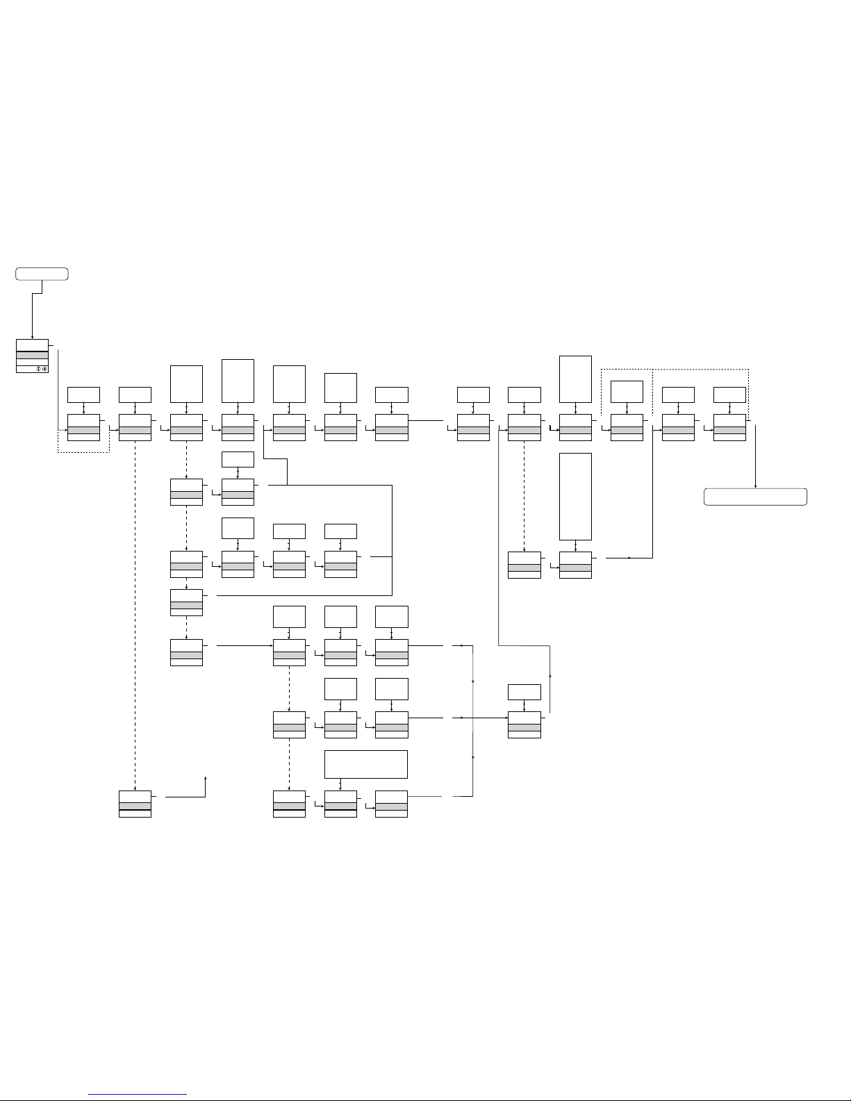
Power up
0000
PASSW.
Txt 1
50.0
%
12.0
3
3
0000
9999
1 2
NO
ADV.SET
Txt 2
NO
YES
1 2
3
VOLT
IN TYPE
Txt 3
VOLT
CURR
LIN.R
POTM
TEMP
1 2
3
2-10
V.RANGE
Txt 4
2-10
0-10
1-5
0-5
0.2-1
0-1
1 2
3
CURR
IN TYPE
Txt 3
3
4-20
I.RANGE
Txt 5
0-20
4-20
1 2
3
LIN.R
IN TYPE
Txt 3
3
3W
CONNEC.
Txt 6
4W
3W
2W
1 2
3
POTM
IN TYPE
Txt 3
3
TEMP
IN TYPE
Txt 3
0
R 0%
Txt 7
0000
9999
1 2
3
2500
R 100%
Txt 8
0000
9999
1 2
3
Pt
SENSOR
Txt 10
Pt
NI
TC
1 2
3
YES
ADV.SET
Txt 2
3
Ni
SENSOR
Txt 10
3
TC
SENSOR
Txt 10
3
100
Pt TYPE
Txt 16
1000
-
10
1 2
3
3W
CONNEC.
Txt 6
4W
3W
2W
1 2
100
Ni TYPE
Txt 17
1000
-
50
1 2
3
3W
CONNEC.
Txt 6
4W
3W
2W
1 2
TC.K
TC.TYPE
Txt 18
TC.B TC.E TC.J TC.K
TC.L TC.N TC.R TC.S
TC.T TC.U TC.W3 TC.W5
TC.Lr
1 2
0.0
DISP.LO
Txt 13
999.9
-199.9
1 2
3
111.1
DEC.P
Txt 12
1111
111.1
11.11
1.111
1 2
3
UNIT
%
Txt 11
@C
mA
rpm
(69 units)
1 2
3
100.0
DISP.HI
Txt 14
999.9
-199.9
1 2
3 3
1.1
CURR
ANA.OUT
Txt 36
VOLT
CURR
1 2
3
4-20
O.RANGE
Txt 37
3
Volt
ANA.OUT
Txt 36
3
0-10
O.RANGE
Txt 39
10-2
10-0
5-1
5-0
1-0.2
1-0
2-10
0-10
1-5
0-5
0.2-1
0-1
1 2
3
23mA
OUT.ERR
Txt 38
23mA
0/3.5mA
NONE
1 2
3
0.0
OUT.LO
Txt 41
4172
-328
1 2
3
150.0
OUT.HI
Txt 42
4172
-328
1 2
1.2
1.3 1.3
3
1.0
3
3
3
@C
UNIT
Txt 9
@C
@F
1 2
3
@C
@F
%
A
bar
cm
ft
ft/h
ft/min
ft/s
g
gal/h
gal/min
GW
hp
hPa
Hz
in
in/h
in/min
in/s
ips
K
kA
kg
kJ
kPa
kV
kW
kWh
l
l/h
l/min
l/s
m
m/h
m/min
m/s
m/s2
m3
m3/h
m3/min
mA
mbar
mils
min
mm
mm/s
mol
MPa
mV
MW
MWh
N
Ohm
Pa
pH
rpm
s
S
t
t/h
uA
um
uS
V
W
Wh
yd
[blank]
3
3
INT
CJC
Txt 63
S20-4
20-4
20-0
S4-20
4-20
0-20
1 2
68
69
1.0 = Etat défaut
Ligne 1 affiche le
signal d’entrée.
Ligne 2 affiche les
unités - UNIT.
En appuyant simul tanément 1 et 2,
l’affichage en ligne
3 alterne entre
A.Out et TAG.
Ligne 4 affiche l’etat
de communication.
1.1 = Seulement si l’in dicateur est protégé
par un mot de
passe.
1.2 = Ne vaut pas pour
les signaux d’entrée :
0...20 mA et
tension.
1.3 = Seulement si le
signal d’entrée est
température.
Diagramme de programmation
Si aucune touche n’est actionnée pendant 1 minute, l’indicateur retourne sur
l’état défaut sans sauvegarde des modifications éventuelles apportées à la
configuration.
1 Incrémenter la valeur / choisir paramètre suivant
2 Décrémenter la valeur / choisir paramètre précédent
3 Valider les valeurs choisies et fin du menu
Maintien 3 Retour au menu précédent / retour au menu 1.0 sans sauvegarde
Continué à la page
Diagramme de programmation ADV.SET
Retour au menu 1.0
Choix de l’UNITE :
Page 37
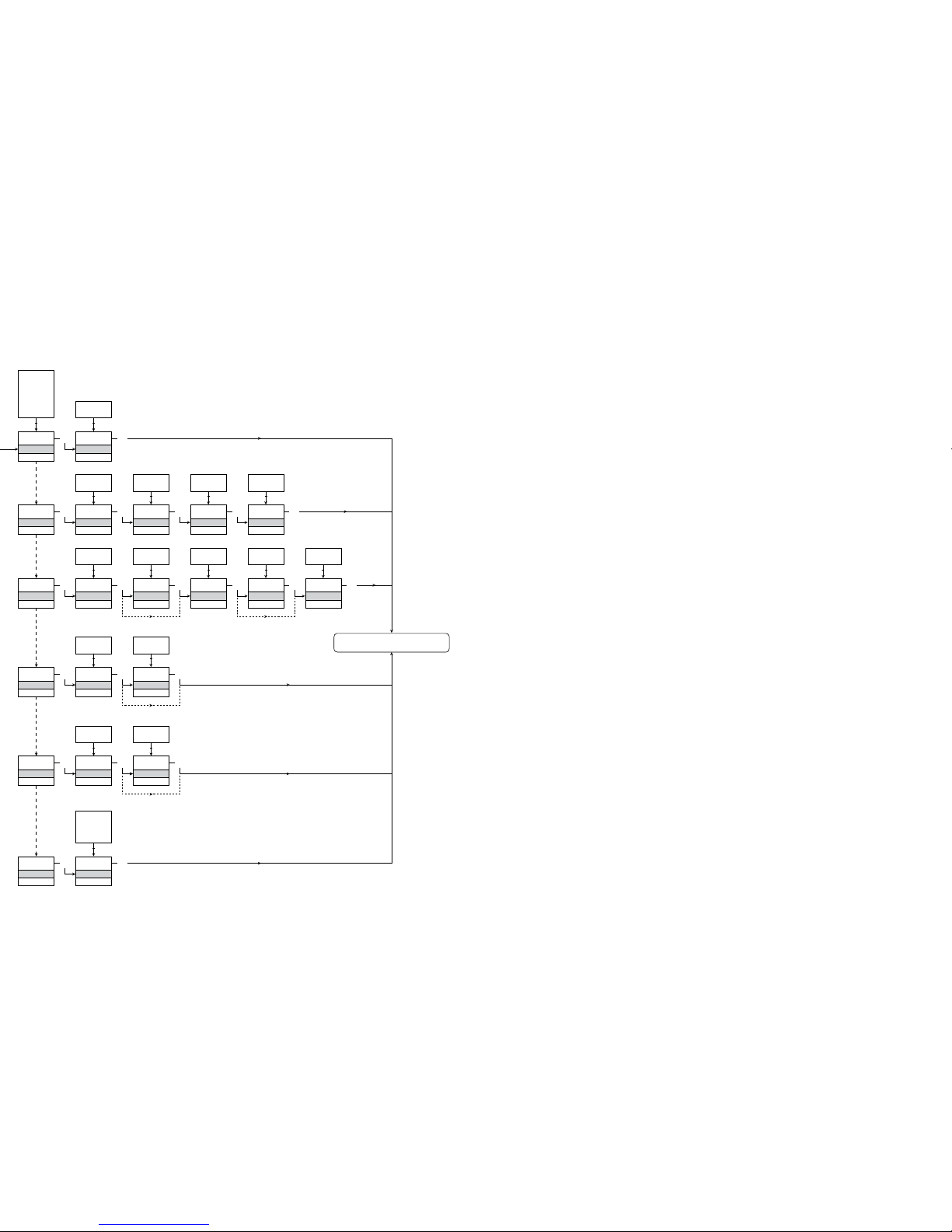
SAVE
MEMORY
Txt 44
3
SAVE
LOAD
1 2
MEM
SETUP
Txt 43
MEM
DISP
CAL
SIM
PASS
LANG
1 2
3
DISP
SETUP
Txt 43
3
3
CONTRA
Txt 45
3
9
0
1 2
9
LIGHT
Txt 46
3
9
0
1 2
VALVE 5
Txt 47
3
9
A
1 2
A.OUT
LINE 3
Txt 48
3
TAG
A.OUT
1 2
CAL
SETUP
Txt 43
3
YES
CAL.LO
Txt 49
3
YES
NO
1 2
2.0
%
Txt 61
3
100.0
0.0
1 2
NO
YES
CAL.HI
Txt 50
3
YES
NO
1 2
90.0
%
Txt 62
3
100.0
0.0
1 2
NO
YES
USE.CAL
Txt 60
3
YES
NO
1 2
SIM
SETUP
Txt 43
3
YES
EN.SIM
Txt 51
3
YES
NO
1 2
25.0
%
Txt 52
3
100.0
0.0
1 2
NO
PASS
SETUP
Txt 43
3 3
YES
EN.PASS
Txt 54
3
YES
NO
1 2
0000
NEW.PAS
Txt 55
3
9999
0000
1 2
LANG
SETUP
Txt 43
3
UK
LANGUA
Txt 59
3
DE, DK,
ES, FR,
IT, SE,
UK
1 2
2.0
NO
70
71
Diagramme de programmation
Réglage avancé (ADV.SET)
Retour au menu 1.0
[01]
[02]
[03]
[04]
[05]
[06]
[07]
[08]
[09]
[10]
[11]
[12]
[13]
[14]
[16]
[17]
[18]
[36]
[37]
[38]
[39]
[41]
[42]
[43]
[44]
[45]
[46]
[47]
[48]
[49]
[50]
[51]
[52]
[54]
[55]
[59]
[60]
[61]
[62]
[63]
Entrer mot de passe correct
Aller dans le menu de configuration avancée ?
Sélectionner entrée température
Sélectionner entrée potentiomètre
Sélectionner entrée résistance linéaire
Sélectionner entrée courant
Selectionner entrée tension
Sélectionner gamme d’entrée 0.0-1 V
Sélectionner gamme d’entrée 0.2-1 V
Sélectionner gamme d’entrée 0-5 V
Sélectionner gamme d’entrée 1-5 V
Sélectionner gamme d’entrée 0-10 V
Sélectionner gamme d’entrée 2-10 V
Sélectionner gamme d’entrée 0-20 mA
Sélectionner gamme d’entrée 4-20 mA
Sélectionner connexion capteur 2-fils
Sélectionner connexion capteur 3-fils
Sélectionner connexion capteur 4-fils
Régler valeur de résistance basse
Régler valeur de résistance haute
Sélectionner Celsius comme unité de température
Sélectionner Fahrenheit comme unité de température
Sélectionner type de capteur TC
Sélectionner type de capteur Ni
Sélectionner type de capteur Pt
Sélectionner unités d’affichage
Sélectionner position du point décimale
Régler gamme d’affichage basse
Régler gamme d’affichage haute
Sélectionner Pt10 comme type de capteur
Sélectionner Pt20 comme type de capteur
Sélectionner Pt50 comme type de capteur
Sélectionner Pt100 comme type de capteur
Sélectionner Pt200 comme type de capteur
Sélectionner Pt250 comme type de capteur
Sélectionner Pt300 comme type de capteur
Sélectionner Pt400 comme type de capteur
Sélectionner Pt500 comme type de capteur
Sélectionner Pt1000 comme type de capteur
Sélectionner NI50 comme type de capteur
Sélectionner NI100 comme type de capteur
Sélectionner NI120 comme type de capteur
Sélectionner NI1000 comme type de capteur
Sélectionner TC-B comme type de capteur
Sélectionner TC-E comme type de capteur
Sélectionner TC-J comme type de capteur
Sélectionner TC-K comme type de capteur
Sélectionner TC-L comme type de capteur
Sélectionner TC-N comme type de capteur
Sélectionner TC-R comme type de capteur
Sélectionner TC-S comme type de capteur
Sélectionner TC-T comme type de capteur
Sélectionner TC-U comme type de capteur
Sélectionner TC-W3 comme type de capteur
Sélectionner TC-W5 comme type de capteur
Sélectionner TC-Lr comme type de capteur
Sélect. courant comme type de sortie analogique
Sélect. tension comme type de sortie analogique
Sélectionner gamme de sortie 0-20 mA
Sélectionner gamme de sortie 4-20 mA
Sélectionner 4-20 mA avec sécurité de la boucle
Sélectionner gamme de sortie 20-0 mA
Sélectionner gamme de sortie 20-4 mA
Sélectionner 20-4 mA avec sécurité de la boucle
Le menu déroulant en ligne 3 de l’indicateur
Sélectionner aucune action d’erreur - la sortie n’est
pas définie en cas d’erreur
Sélectionner bas d’échelle en cas d’erreur
Sélect. NAMUR NE43 bas d’échelle en cas d’erreur
Sélect. NAMUR NE43 haut d’échelle en cas d’erreur
Sélectionner gamme de sortie 0.0-1 V
Sélectionner gamme de sortie 0.2-1 V
Sélectionner gamme de sortie 0-5 V
Sélectionner gamme de sortie 1-5 V
Sélectionner gamme de sortie 0-10 V
Sélectionner gamme de sortie 2-10 V
Sélectionner gamme de sortie 1-0.0 V
Sélectionner gamme de sortie 1-0.2 V
Sélectionner gamme de sortie 5-0 V
Sélectionner gamme de sortie 5-1 V
Sélectionner gamme de sortie 10-0 V
Sélectionner gamme de sortie 10-2 V
Régler la température basse de la sortie analogique
Régler la température haute de la sortie analogique
Aller dans la configuration du mot de passe
Aller dans le mode simulation
Exécuter calibration de process
Aller dans la configuration d’affichage
Exécuter opérations de mémoire
Charger la configuration sauvegardée en 4114
Sauvegarder la configuratioin du 4114 dans le 4501
Ajuster le contraste LCD
Ajuster le rétro-éclairage LCD
Entrer numéro repère de 6 caractères
Valeur de la sortie analogique affichée en ligne 3
Numéro repère affiché en ligne 3
Calibrer l’entrée basse à la valeur de process ?
Calibrer l’entrée haute à la valeur de process ?
Permettre mode de simulation ?
Régler la valeur de simulation en entrée
Permettre protection par mot de passe ?
Entrer nouveau mot de passe
Sélectionner langue
Utiliser valeurs de calibration process ?
Régler valeur de la position basse de la calibration
Régler valeur de la position haute de la calibration
Sélectionner compensation soudure froide externe
CJC (Accessoire)
Sélectionner compensation soudure froide interne
2.0 Dans le sous-menu simulation (SIM) il faut
actionner 3 pour retourner sur l’état defaut 1.0
Page 38

72
73
UNIVERSAL-MESSUMFORMER
PReasy 4114
INHALTSVERZEICHNIS
Warnungen ......................................................................... 74
Sicherheitsregeln ................................................................ 75
Konformitätserklärung ........................................................ 77
Zerlegung des Systems 4000 ............................................ 78
Wenn die Front LED rot leuchtet / Display zeigt AO.ER .... 78
Erweiterte Merkmale .......................................................... 79
Verwendung ........................................................................ 79
Technische Merkmale ......................................................... 79
PR 4501 Display / Programmierfront ................................. 80
Anwendungen .................................................................... 81
Bestellangaben ................................................................... 82
Elektrische Daten ............................................................... 82
Visualisierung im 4501: Sensorfehlererkennung und
Eingangssignal außerhalb des Bereichs ............................ 85
Grenzen Fühlerfehlererkennung ......................................... 86
Fehleranzeige ..................................................................... 86
Anschlüsse ......................................................................... 87
Blockdiagramm .................................................................. 88
Konfiguration / Bedienung der Funktionstasten ................ 89
Flussdiagramm ................................................................... 92
Flussdiagramm, Erweiterte Einstellungen (ADV.SET) ......... 94
Scrollender Hilfetext im Display Zeile 3 ............................. 95
Page 39
74
75
ZEICHENERKLÄRUNGEN
Dreieck mit Ausrufungszeichen: Warnung / Vorschrift. Vorgänge, die zu
lebensgefährlichen Situationen führen können.
Die CE-Marke ist das sichtbare Zeichen dafür, dass das Gerät die
Vorschriften erfüllt.
Doppelte Isolierung ist das Symbol dafür, dass das Gerät
besondere Anforderungen an die Isolierung erfüllt.
SICHERHEITSREGELN
DEFINITIONEN:
Gefährliche Spannungen sind definitionsgemäß die Bereiche: 75...1500 Volt
Gleichspannung und 50...1000 Volt Wechselspannung.
Techniker sind qualifizierte Personen, die dazu ausgebildet oder angelernt sind,
eine Installation, Bedienung oder evtl. Fehlersuche auszuführen, die sowohl
technisch als auch sicherheitsmäßig vertretbar ist.
Bedienungspersonal sind Personen, die im Normalbetrieb mit dem Produkt die
Drucktasten oder Potentiometer des Produktes einstellen bzw. bedienen und
die mit dem Inhalt dieses Handbuches vertraut gemacht wurden.
EMPFANG UND AUSPACKEN:
Packen Sie das Gerät aus, ohne es zu beschädigen und kontrollieren Sie beim
Empfang, ob der Gerätetyp Ihrer Bestellung entspricht. Die Ver packung sollte
beim Gerät bleiben, bis dieses am endgültigen Platz montiert ist.
UMGEBUNGSBEDINGUNGEN:
Direkte Sonneneinstrahlung, starke Staubentwicklung oder Hitze, mechanische
Erschütterungen und Stöße sind zu vermeiden; das Gerät darf nicht Regen oder
starker Feuchtigkeit ausgesetzt werden. Bei Bedarf muss eine Erwärmung, welche die angegebenen Grenzen für die Umgebungstemperatur überschreitet, mit
Hilfe eines Kühlgebläses verhindert werden.
Alle Geräte gehören der Installationskategorie II, dem Verschmutzungsgrad 1
und der Isolationsklasse II an.
INSTALLATION:
Das Gerät darf nur von Technikern angeschlossen werden, die mit den technischen Ausdrücken, Warnungen und Anweisungen im Handbuch vertraut sind
und diese befolgen.
Sollten Zweifel bezüglich der richtigen Handhabung des Gerätes bestehen,
sollte man mit dem Händler vor Ort Kontakt aufnehmen. Sie können aber auch
direkt mit PR electronics GmbH, Im Erlengrund 26, D-46149 Oberhausen,
WARNUNG!
Dieses Gerät ist für den Anschluss an lebensgefährliche elektrische Spannungen gebaut. Missachtung dieser Warnung
kann zu schweren Verletzungen oder mechanischer Zerstörung
führen.
Um eine Gefährdung durch Stromstöße oder Brand zu vermeiden müssen die Sicherheitsregeln des Handbuches eingehalten,
und die Anweisungen befolgt werden.
Die Spezifikationswerte dürfen nicht überschritten werden, und
das Gerät darf nur gemäß folgender Beschreibung benutzt
werden. Das Handbuch ist sorgfältig durchzulesen, ehe das
Gerät in Gebrauch genommen wird. Nur qualifizierte Personen
(Techniker) dürfen dieses Gerät installieren.
Wenn das Gerät nicht wie in diesem Handbuch beschrieben
benutzt wird, werden die Schutzeinrichtungen des Gerätes
be einträchtigt.
WARNUNG
Das System 4000 muss auf eine DIN-Schiene nach DIN 46277
montiert werden.
WARNUNG!
Vor dem abgeschlossenen festen Einbau des Gerätes darf
daran keine gefährliche Spannung angeschlossen werden, und
folgende Maßnahmen sollten nur in spannungslosem Zustand
des Gerätes und unter ESD-sicheren Verhältnisse durchgeführt
werden:
Installation, Montage und Demontage von Leitungen.
Fehlersuche im Gerät.
Reparaturen des Gerätes und Austausch von Sicherungen
dürfen nur von PR electronics A/S vorgenommen werden.
GEFÄHR-
LICHE
SPANNUNG
INSTAL-
LATION
ALLGE -
MEINES
WARNUNG
Die Frontplatte des Gerätes darf nicht geöffnet werden, weil hierdurch die Kontakte zur Kontaktierung des Frontdisplays 4501
beschädigt werden können. Das Gerät enthält keine internen
DIP-Schalter oder Programmierbrücken.
Page 40

76
77
KONFORMITÄTSERKLÄRUNG
Als Hersteller bescheinigt
PR electronics A/S
Lerbakken 10
DK-8410 Rønde
hiermit für das folgende Produkt:
Typ: 4114
Name: Universal-Messumformer
die Konformität mit folgenden Richtlinien und Normen:
Die EMV Richtlinien 2004/108/EG und nachfolgende Änderungen
EN 61326-1
Zur Spezifikation des zulässigen Erfüllungsgrades, siehe die Elektrische
Daten des Gerätes.
Die Niederspannungsrichtlinien 2006/95/EG und nachfolgende Änderungen
EN 61010-1
Rønde, 20. August 2009 Kim Rasmussen
Unterschrift des Herstellers
(Tel.: (0) 208 62 53 09-0) oder mit PR electronics A/S, Lerbakken 10,
DK-8410 Rønde, Dänemark (Tel.: +45 86 37 26 77) Kontakt aufnehmen.
Die Installation und der Anschluss des Gerätes haben in Übereinstimmung mit
den geltenden Regeln des jeweiligen Landes bez. der Installation elektrischer
Apparaturen zu erfolgen, u.a. bezüglich Leitungsquerschnitt, (elektrischer) VorAbsicherung und Positionierung.
Eine Beschreibung von Eingangs- / Ausgangs- und Versorgungsanschlüssen
befindet sich auf dem Blockschaltbild und auf dem seitlichen Schild.
Für Geräte, die dauerhaft an eine gefährliche Spannung angeschlossen sind, gilt:
Die maximale Größe der Vorsicherung beträgt 10 A und muss zusammen mit einem Unterbrecherschalter leicht zugänglich und nahe am
Gerät angebracht sein. Der Unterbrecherschalter soll derart gekennzeichnet sein, dass kein Zweifel darüber bestehen kann, dass er die
Spannung für das Gerät unterbricht.
UL-EINBAUVORSCHRIFTEN:
Nur 60/75°C Kupferleiter anwenden
Nur für Anwendung in Verschmutzungsgrad 2 oder besser
Max. Umgebungstemperatur ......................... 60°C
Max. Leitungsquerschnitt ............................... AWG 26-14
UL Dateinummer ............................................ E231911
KALIBRIERUNG UND JUSTIERUNG:
Während der Kalibrierung und Justierung sind die Messung und der Anschluss
externer Spannungen entsprechend diesem Handbuch auszuführen, und
der Techniker muss hierbei sicherheitsmäßig einwandfreie Werkzeuge und
Instrumente benutzen.
BEDIENUNG IM NORMALBETRIEB:
Das Bedienungspersonal darf die Geräte nur dann einstellen oder bedienen,
wenn diese auf vertretbare Weise in Schalttafeln o. ä. fest installiert sind, sodass
die Bedienung keine Gefahr für Leben oder Material mit sich bringt. D. h., es
darf keine Gefahr durch Berührung bestehen, und das Gerät muss so plaziert
sein, dass es leicht zu bedienen ist.
REINIGUNG:
Das Gerät darf in spannungslosem Zustand mit einem Lappen gereinigt werden,
der mit destilliertem Wasser leicht angefeuchtet ist.
HAFTUNG:
In dem Umfang, in welchem die Anweisungen dieses Handbuches nicht
genau eingehalten werden, kann der Kunde PR electronics gegenüber keine
Ansprüche geltend machen, welche ansonsten entsprechend der eingegangenen Verkaufs vereinbarungen existieren können.
Page 41
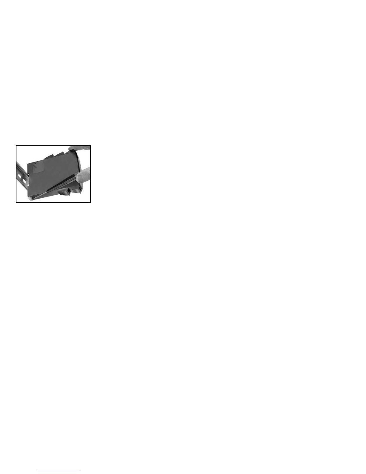
78
79
UNIVERSAL-MESSUMFORMER
PReasy 4114
• Eingang für WTH, TE, Ohm, Potmeter, mA und V
• 2-Draht-Versorgung > 16 V
• FM-Zulassung für Installation in Div. 2
• Ausgänge für Strom und Spannung
• Universelle Versorgung mit AC oder DC
Erweiterte Merkmale:
• Programmierbar mittels abnehmbare Frontdisplay (4501), Prozesskalibrierung,
Signalsimulierung, Passwortschutz, Fehlerdiagnose und Wahl von Hilfetext
auf mehreren Sprachen.
Verwendung:
• Elektronische, lineare Temperaturmessung mit Widerstandssensor oder
Thermoelementsensor.
• Umwandlung von linearer Widerstandsänderung in ein analoges Standardstrom / -Spannungssignal, z. B. von Magnetventilen, Schmetterlingsventilen
oder lineare Bewegungen mit angeschlossene Potentio meter.
• Spannungsversorgung und Signaltrenner für 2-Draht-Messumformer.
• Prozesssteuerung mit standard Analogausgang.
• Galvanische Trennung von Analogsignalen und Messung von Signalen, die
nicht massegebunden sind.
• Das 4114 ist gemäß den strengsten Sicherheitsrichtlinien entwickelt und
somit in Installationen mit SIL 2 Applikationen einsetzbar.
Technische Merkmale:
• Wenn das 4114 in Kombination mit der Programmierfront eingesetzt wird,
können alle operativen Parameter der entsprechenden Applikation angepasst
werden. Das 4114 ist mit elektronischen Hardware-Schaltern ausgestattet und
es ist nicht notwendig das Gerät zur Einstellung von DIP-Schaltern zu öffnen.
• Eine grüne / rote Leuchtdiode in der Front des Gerätes zeigt den normalen
Betrieb und Fehlfunktionen an.
• Ständige Prüfung wichtiger Speicherdaten aus Sicherheitsgründen.
• 2,3 kVAC galvanische Trennung der 3 Ports.
ZERLEGUNG DES SYSTEMS 4000
Zunächst ist gefährliche Spannung von den Anschlussklemmen zu trennen.
Abbildung 1:
Das Gerät wird von der DIN-Schiene
gelöst, indem man den unteren
Verschluss löst.
Wenn die rote LED in der Front leuchtet / Display zeigt AO.ER:
PR 4114 ist als SIL-2-Gerät mit einem hohen Sicherheitsniveau entwickelt wor-
den. Deshalb erfolgt eine kontinuierliche Messung des Ausgangs-Stromes
bei dem 4...20 mA -Ausgangssignal. Wenn der Strom 0 mA ist, schaltet das
Gerät in den Fehler-Modus und die LED-Anzeige leuchtet rot. Diese Funktion
ist keine Standard-Option, sondern muss aktiv im Menü ausgewählt werden.
Der Fehler-Modus kann nur zurückgesetzt werden durch Aus- und wieder
Einschalten der Spannungsversorgung des Gerätes
Page 42
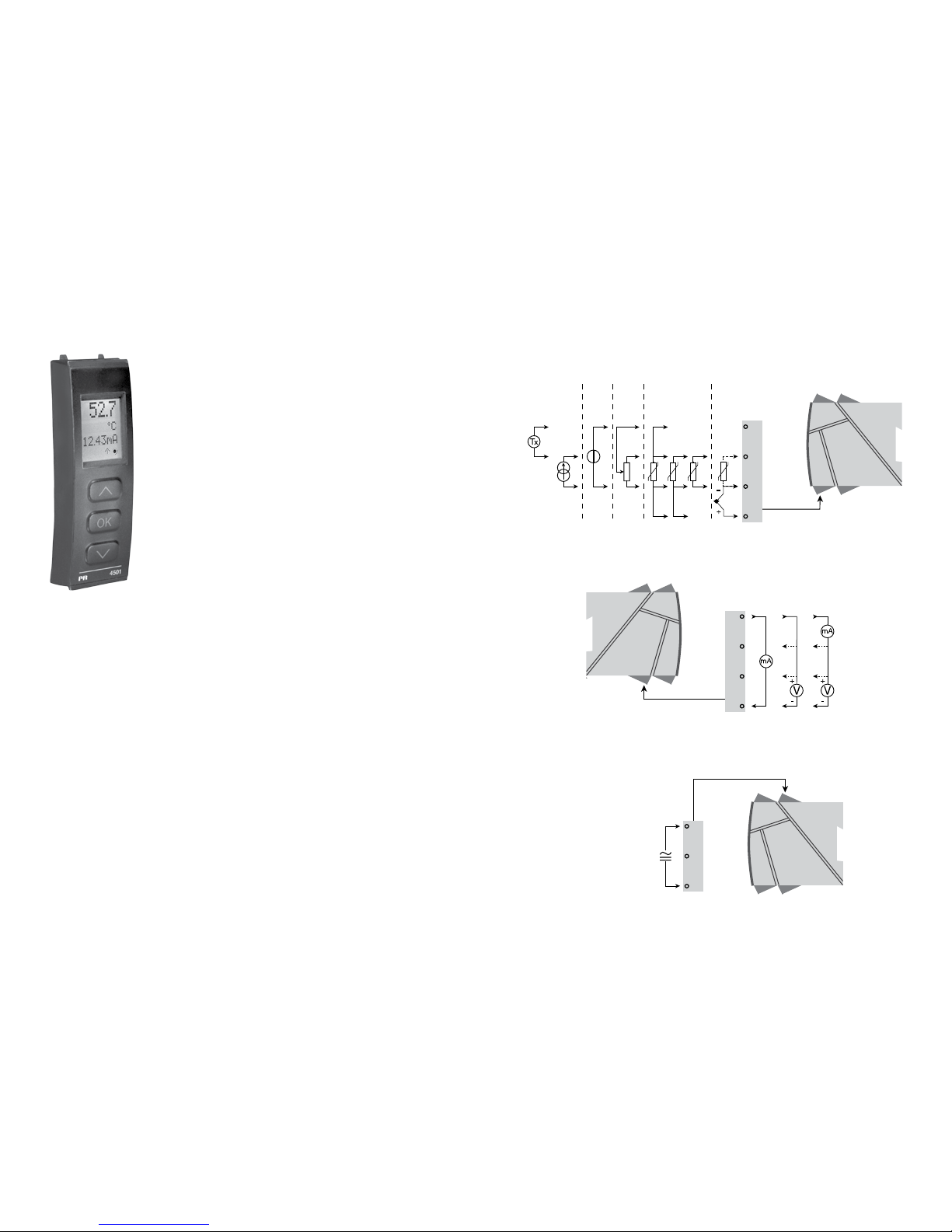
+
-
+
-
44
43
42
41
12
14
13
11
+
-
10 V
1 V
+
-
10 V
1 V
33
32
31
*
80
81
PR 4501 DISPLAY / PROGRAMMIERFRONT
Funktionallität:
Die einfache PReasy Menüstruktur leitet automatisch
durch die relevanten Einstellungen. Der scrollende
Hilfetext macht es sehr einfach diese Geräte einzusetzen. Sie finden weitere Beschreibungen der Funktionen
und Programmierungsmög lichkeiten im Abschnitt
”Konfiguration / Bedienung der Funktionstasten”.
Anwendungen:
• Kommunikationsschnittstelle zur Änderung der operativen Parameter im 4114.
• Kann von einem 4114 auf das nächste gesteckt werden um die Daten des
ersten Messumformers auf den nächsten zu übertragen.
• Stationäres Display zur Visualisierung der Prozessdaten und des Status.
Technische Merkmale:
• LCD Display mit 4 Zeilen; Zeile 1 (5,57 mm hoch) zeigt das Eingangssignal,
Zeile 2 (3,33 mm hoch) die Einheiten, Zeile 3 (3,33 mm hoch) den Analogausgang oder den Geräte-TAG und Zeile 4 den Kommunikationsstatus an.
• Der Zugriff auf die Programmierung kann mit der Eingabe eines Passwortes
blockiert werden. Das Passwort wird im Messumformer gespeichert, um
den höchsten Grad an Schutz gegen nicht autorisierte Änderungen der
Konfiguration sicherzustellen.
Montage / Installation:
• Stecke das 4501 auf die Front des 4114.
ANWENDUNGEN
Eingangssignale:
Strom
Span-
nung
Potenti-
ometer
WTH und lin. R TE
Verbindung, Leiter
Ausgangssignale:
Versorgung:
21,6...253 VAC
oder
19,2...300 VDC
Analog, 0/4...20 mA und Spannung
*Bitte die CJC-Anschlussklemme Typ 5910
separat bestellen!
Page 43
82
83
Hilfsspannungen:
2-Draht-Versorgung (Klemme 44...43) ........ 25...16 VDC / 0...20 mA
Leitungsquerschnitt (max.) .......................... 1 x 2,5 mm
2
Litzendraht
Klemmschraubenanzugsmoment ................ 0,5 Nm
Relative Luftfeuchtigkeit .............................. < 95% RF (nicht kond.)
Abmessungen, ohne Frontdisplay (HxBxT) .. 109 x 23,5 x 104 mm
Abmessungen, mit Frontdisplay (HxBxT) .... 109 x 23,5 x 116 mm
Schutzart ..................................................... IP20
Gewicht ....................................................... 145 g / 160 g mit 4501
WTH-, linearer Widerstands- und Potentiometereingang:
Eingang für TE-Typen:
Pt10, Pt20, Pt50, Pt100, Pt200, Pt250, Pt300, Pt400, Pt500, Pt1000
Ni50, Ni100, Ni120, Ni1000
Kabelwiderstand pro Leiter (max.), WTH .... 50 Ω
Fühlerstrom, WTH ....................................... Nom. 0,2 mA
Wirkung des Leitungswiderstandes
(3- / 4-Leiter), WTH ..................................... < 0,002 Ω / Ω
Fühlerfehlererkennung, WTH ....................... Ja
Kurzschlusserkennung, WTH ...................... < 15 Ω
EMV Störspannungseinfluss ............................... < ±0,5% d. Messsp.
Erweitere EMV Störfestigkeit:
NAMUR NE 21, Kriterium A, Burst ...................... < ±1% d. Messsp.
Eingangs-
art
Min.
Wert
Max.
Wert
Norm
Pt100
Ni100
Lin. R
Potentiometer
-200°C
-60°C
0 Ω
10 Ω
+850°C
+250°C
10000 Ω
100 kΩ
IEC60751
DIN 43760
-
-
Bestellangaben:
4114 = Universal-Messumformer
4501 = Display / Programmierfront
5910 = CJC-Anschlussklemme
Elektrische Daten:
Umgebungstemperatur ............................... -20°C bis +60°C
Allgemeine Daten:
Universelle Versorgungsspannung .............. 21,6...253 VAC, 50...60 Hz
oder 19,2...300 VDC
Stromverbrauch max. .................................. ≤ 2,0 W
Sicherung .................................................... 400 mA SB / 250 VAC
Isolationsspannung, Test / Betrieb .............. 2,3 kVAC / 250 VAC
Kommunikationsschnittstelle ...................... Programmierfront 4501
Signal- / Rauschverhältnis .......................... Min. 60 dB (0...100 kHz)
Ansprechzeit (0...90%, 100...10%):
Temperatureingang ................................. ≤ 1 s
mA- / V-Eingang...................................... ≤ 400 ms
Kalibrierungstemperatur .............................. 20...28°C
Genauigkeit: Der höhere Wert der allgemeinen Werte oder Grundwerte:
Allgemeine Werte
Eingangs-
art
Absolute
Genauigkeit
Temperatur-
koeffizient
Alle ≤ ±0,1% d. Messsp. ≤ ±0,01% Messsp. / °C
Grundwerte
Eingangs-
art
Grund-
genauigkeit
Temperatur-
koeffizient
mA ≤ ±4 µA ≤ ±0,4 µA / °C
Volt ≤ ±20 µV ≤ ±2 µV / °C
Pt100 ≤ ±0,2°C ≤ ±0,01°C / °C
Lin. R ≤ ±0,1 Ω ≤ ±0,01 Ω / °C
Potentiometer ≤ ±0,1 Ω ≤ ±0,01 Ω / °C
TE-Typ:
E, J, K, L, N, T, U
≤ ±1°C
≤ ±0,05°C / °C
TE-Typ: R, S, W3,
W5, LR
≤ ±2°C
≤ ±0,2°C / °C
TE-Typ: B
160...400°C
≤ ±4,5°C
≤ ±0,45°C / °C
TE-Typ: B
400...1820°C
≤ ±2°C
≤ ±0,2°C / °C
Page 44

84
85
Belastung (max.) .......................................... 20 mA / 800 Ω / 16 VDC
Belastungsstabilität ..................................... ≤ 0,01% d. Messspanne / 100 Ω
Fühlerfehlererkennung ................................. 0 / 3,5 / 23 mA / keine
NAMUR NE 43 Up- / Downscale ................ 23 mA / 3,5 mA
Ausgangsbegrenzung:
4...20 und 20...4 mA Signale ................... 3,8...20,5 mA
0...20 und 20...0 mA Signale ................... 0...20,5 mA
Strombegrenzung ........................................ ≤ 28 mA
Spannungsausgang:
Signalbereich ............................................... 0...10 VDC
Programmierbare Signalbereiche ................ 0...1 / 0,2...1 / 0...10 / 0...5 /
1...5 / 2...10 / 1...0 / 1...0,2 / 5...0 /
5...1 / 10...0 og 10...2 V
Belastung (min.) ........................................... 500 kΩ
Ex- / I.S.-Zulassung:
FM, Anwendungsbereich in......................... Class I, Div. 2, Group A, B, C, D
Class I, Div. 2, Group IIC
Zone 2
Max. Umgebungstemperatur für T5 ............ 60°C
Marine-Zulassung:
Det Norske Veritas, Ships & Offshore ......... Standard for Certification No. 2.4
GOST R Zulassung:
VNIIM, Cert. no. ........................................... Siehe www.prelectronics.de
Eingehaltene Richtlinien: Norm:
EMV 2004/108/EG ....................................... EN 61326-1
LVD 2006/95/EG .......................................... EN 61010-1
FM ............................................................... 3600, 3611, 3810 und ISA 82.02.01
UL, Standard for Safety .............................. UL 508
d. Messspanne = der momentan gewählten Messspanne
Visualisierung im 4501: Sensorfehlererkennung und
Eingangssignal außerhalb des Bereichs
Sensorfehlerprüfung:
Gerät: Konfiguration Fühlerfehlererkennung
4114
OUT.ERR=NONE. OFF
Sonst: ON
TE-Eingang:
Vergleichsstellenkompensation (CJC):
über externen Sensor in der
Anschlussklemme 5910 .......................... 20...28°C ≤ ± 1°C
-20...20°C /
28...70°C ≤±2°C
über internen CJC-Sensor ...................... ±(2,0°C + 0,4°C * Δt)
Δt = interne Temperatur-Umgebungstemperatur
Fühlerfehlererkennung, alle TE-Typen ......... Ja
Fühlerfehlerstrom:
Bei Erkennung ......................................... Nom. 2 µA
Sonst ....................................................... 0 µA
Stromeingang:
Messbereich ................................................ 0...20 mA
Programmierbare Messbereiche ................. 0...20 und 4...20 mA
Eingangswiderstand .................................... Nom. 20 Ω + PTC 50 Ω
Fühlerfehlererkennung:
Schleifenunterbrechung 4...20 mA......... Ja
Spannungseingang:
Messbereich ................................................ 0...12 VDC
Programmierbare Messbereiche ................. 0...1 / 0,2...1 / 0...5 / 1...5 /
0...10 und 2...10 VDC
Eingangswiderstand .................................... Nom. 10 MΩ
Stromausgang:
Signalbereich (Spanne) ............................... 0...20 mA
Programmierbare Signalbereiche ................ 0...20 / 4...20 / 20...0 / 20...4 mA
Typ
Min.
Wert
Max.
Wert
Norm
B
E
J
K
L
N
R
S
T
U
W3
W5
LR
0°C
-100°C
-100°C
-180°C
-200°C
-180°C
-50°C
-50°C
-200°C
-200°C
0°C
0°C
-200°C
+1820°C
+1000°C
+1200°C
+1372°C
+900°C
+1300°C
+1760°C
+1760°C
+400°C
+600°C
+2300°C
+2300°C
+800°C
IEC 60584-1
IEC 60584-1
IEC 60584-1
IEC 60584-1
DIN 43710
IEC 60584-1
IEC 60584-1
IEC 60584-1
IEC 60584-1
DIN 43710
ASTM E988-90
ASTM E988-90
GOST 3044-84
Page 45
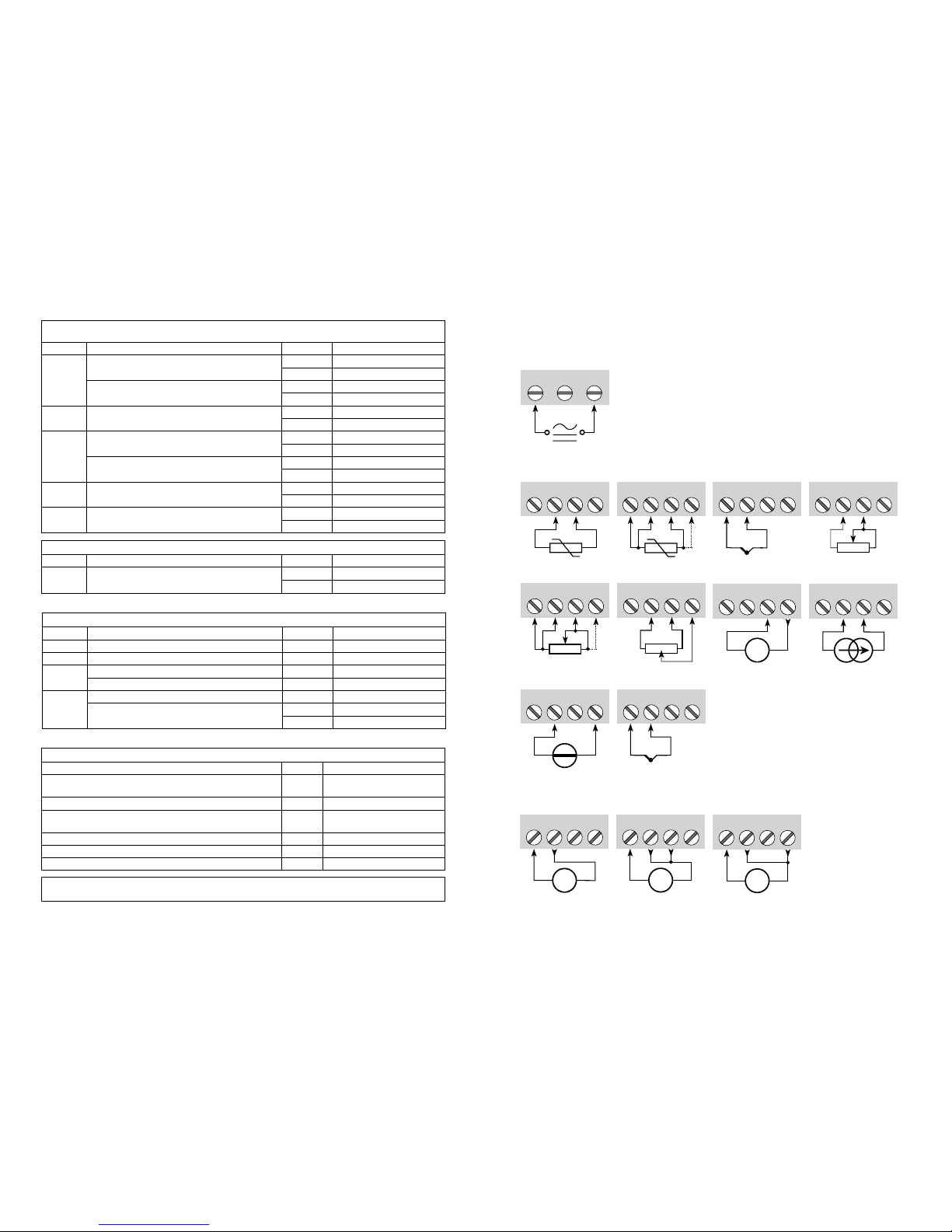
11 12 14
13
+
-
V
11 12 14
13
+
-
V
11 12 14
13
+
-
mA
+
-
41 42 44
43
41 42 44
43
42 44
43
41 41 42 44
43
41 42 44
43
+
-
41 42 44
43
+
-
41 42 44
43
+
-
Tx
41 42 44
43
31 32 33
41 42 44
43
+
-
41 42 44
CJC
86
87
ANSCHLÜSSE
Eingänge
Ausgänge
Versorgung:
Spannung, 1 V Spannung, 10 VStrom
WTH, 3- / 4-LeiterWTH, 2-Leiter
Widerstand,
2-Leiter
Widerstand,
3- / 4-Leiter
Potentiometer
Strom2-Draht-Umformer
Spannung
Grenzen Fühlerfehlererkennung:
Fehleranzeige:
Außerhalb des Bereichs Anzeige (IN.LO, IN.HI):
Bei Verlassen des Gewählten Bereichs des A/D-Wandlers oder des Polynoms.
Eingang Bereich Anzeige Grenze
VOLT
0...1 V / 0,2...1 V
IN.LO < -25 mV
IN.HI > 1,2 V
0...10 V / 2...10 V
IN.LO < -25 mV
IN.HI > 12 V
CURR 0...20 mA / 4...20 mA
IN.LO < -1,05 mA
IN.HI > 25,05 mA
LIN.R
0...800
Ω
IN.LO < 0 Ω
IN.HI > 1075 Ω
0...10 kΩ
IN.LO < 0 Ω
IN.HI < 110 kΩ
POTM -
IN.LO < -0,5 %
IN.HI > 100,5 %
TEMP TE / WTH
IN.LO < Temperaturbereich -2°C
IN.HI > Temperaturbereich +2°C
Fühlerfehlererkennung (SE.BR, SE.SH):
Eingang Bereich Anzeige Grenze
CURR Schleife unterbrochen (4...20 mA) SE.BR <= 3,6 mA; > = 21 mA
POTM Alle, SE.BR auf alle 3-Leiter SE.BR > ca. 126 k
Ω
LIN.R
0...800
Ω SE.BR > ca. 875 Ω
0...10 kΩ SE.BR > ca. 11 kΩ
TEMP
TC SE.BR > ca. 750 k
Ω / (1,25 V)
WTH, 2-, 3- und 4-Leiter
Kein SE.SH für Pt10, Pt20 und Pt50
SE.BR > ca. 15 k
Ω
SE.SH < ca. 15 Ω
Display Anzeige unter Min.- / über Max. (-1999, 9999):
Eingang Bereich Anzeige Grenze
Alle Alle
-1999 Display Anzeige <-1999
9999 Display Anzeige >9999
! Fehleranzeige im Display blinkt einmal pro Sekunde. Der Hilfetext erklärt den Fehler.
1) Um das Gerät zurückzusetzen, muss die Versorgungsspannung kurz unterbrochen werden.
Anzeige bei Hardwarefehler
Fehlersuche Anzeige Fehlergrund
Test des internen CJC-Fühlers CJ.ER
CJC-Fühler defekt oder Temp.
außerh. des Bereichs
Checksum Test der Konfiguration im FLASH FL.ER Fehler im FLASH
Überprüfe Messung der analoger ausgangsspannung AO.ER
1) Stromausg. ist unbelastet
(nur S4...20 mA/S20...4 mA)
Überprüfe Kommunikation zwischen 4501 / 4114 NO.CO Verbindungsfehler
Überprüfe ob Eingangssignal an Eingangskonfiguration passt IN.ER 1) Fehlerniv. im Eingang
Überprüfe ob Konfiguration im 4501 Speicher an 4114 passt TY.ER Konfiguration ist nicht 4114
TE, interner
CJC-Sensor
*TE, CJC-
Anschlussklemme
* Bitte die CJC-Anschlussklemme
5910 separat bestellen.
Page 46
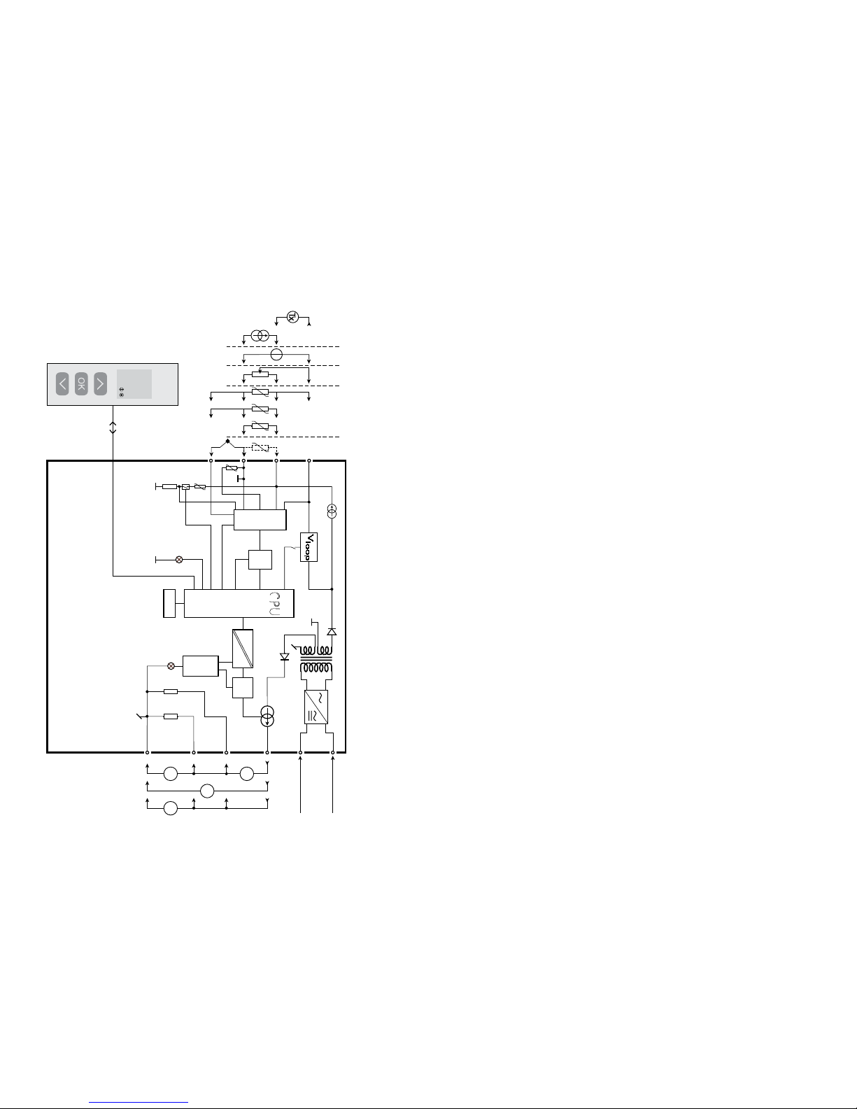
50.0
VALVE 5
l / min
4114
4
3
2
+
-
+
-
11
13
14
500Ω
50Ω
33
31
12
D / A
Safety
A / D
PTC
CJC
0.2 mA
43
44
42
41
10 Ω
MUX
EEPROM
CPU
VV
mA
mA
I+
10 V
1 V
+
-
*
88
89
KONFIGURATION /
BEDIENUNG DER FUNKTIONSTASTEN
Dokumentation für das Flussdiagramm.
Grundsätzliches:
Bei der Konfiguration des 4114 werden Sie durch alle Parameter geleitet und
Sie können die Einstellungen wählen, welche zur Applikation passt. Für jedes
Menü existiert ein scrollender Hilfetext welcher automatisch in der 3. Zeile im
Display gezeigt wird.
Die Konfiguration wird mittels der 3 Funktionstasten durchgeführt:
1 erhöht den numerischen Wert oder wählt nächsten Parameter
2setzt den numerischen Wert herab oder wählt nächsten Parameter
3übernimmt den gewählten Wert und beendet das Menü
Wenn eine Konfiguration eingegeben worden ist, kehrt das Display auf den
Menüpunkt 1.0 zurück
Bei drücken und halten von
3 springt man zurück zum vorherigen Menü oder
in den Normal-Zustand (1.0) ohne die geänderten Werte oder Parameter zu
speichern.
Wenn für 1 Minute keine Taste betätigt wird, geht das Display in den Normal-
Zustand zurück, ohne die geänderten Werte oder Parameter zu speichern.
Weitere Erklärungen:
Passwortschutz: Der Zugriff auf die Programmierung kann mit der Eingabe
eines Passwortes blockiert werden. Das Passwort wird im Messumformer
gespeichert, um den höchsten Grad an Schutz gegen nicht autorisierte
Änderungen der Konfiguration sicherzustellen. Bei Eingabe des MasterPasswortes 2008 sind alle Konfigurationsmenüs erreichbar.
Signal- und Sensorfehlerinformation per Programmierfront 4501
Sensorfehler (s. Grenzen im Diagramm), wird als SE.BR (Sensorfehler) oder
SE.SH (Fühlerkurzschluss) angezeigt. Signale, ausserhalb des gewählten Bereichs (kein Sensorfehler, s. Tabelle für Grenzen), werden als IN.LO
(niedriges Eingangssignal) oder IN.HI (hohes Eingangssignal) angezeigt.
Die Fehlermeldung wird in der 3. Zeile als Text mit blinkender Hintergrundbeleuchtung angezeigt. Zeile 4 der Anzeige zeigt den Zustand der
Kommunikation an: COM (blinkendes Kugelsymbol) zeigt an, ob das 4501 korrekt funktioniert und hoch/runter Pfeile zeigen tendenziell das Eingangssignal an.
BLOCKDIAGRAMM
Potentiometer
2-Draht-Umformer
Spannung
Strom
WTH und lin.R,
Verbindung,
Leiter
Versorgung
Versorgung
21,6...250 VAC oder
19,2...300 VDC
Erde
I + V
Ausg.
I
Ausg.
V
Ausg.
TE
Grün
Rot
* Bitte die CJC-Anschlussklemme 5910 separat bestellen.
Page 47

90
91
Signal und Senfohlerfehleranzeige ohne Programmierfront
Der Status des Gerätes kann auch durch die rote/grüne LED an der Gerätefront
abgelesen werden.
Grün blinkende LED 13 Hz zeigt normalen Betrieb an.
Grün blinkende LED 1 Hz zeigt Sensorfehler an.
Dauernd grün leuchtende LED zeigt internen Fehler an.
Dauernd rot leuchtende LED signalisiert einen schwerwiegenden Fehler.
Hauptfunktionen
Das Gerät bietet Zugang zu verschiedenen Funktionen, welche mit “yes“ bei der
Abfrage „adv.set“ bestätigt werden muß.
Anzeigeeinstellungen: Sie können Werte einstellen, wie Displaykontrast
und Hintergrundhelligkeit. Einstellung der TAG-Nummer mit 6 alphanumerischen Werten. Auswahl der Anzeigefunktion in der dritten Zeile zwischen
Analogausgang oder TAG Nummer.
Zweipunkt Prozesskalibrierung: Mit dem Gerät kann mit zwei Punkten des
Eingangssignals eine Prozesskalibrierung durchgeführt werden. Ein niedriges
Eingangssignal (nicht unbedingt 0%) muss anliegen und der aktuelle Wert
wird über das 4501 eingegeben. Dann wird ein höherer Wert (nicht unbedingt
100%) angelegt und der aktuelle Wert wird über das 4501 eingegeben. Wenn
Sie die Kalibrierung akzeptieren, wird das Gerät mit den neuen Werten übernommen. Wenn Sie später diese Werte verwerfen oder andere Parameter
eingeben, wird die Werkskalibrierung übernommen.
Prozesssimulationsfunktion: Wenn Sie die Abfrage “EN.SIM” bestätigen, ist
es möglich ein Eingangssignal zu simulieren, d.h. die hoch/runter Tasten kontrollieren das Ausgangssignal. Wenn Sie mit 3 bestätigen, springt das Gerät
wieder in den Normalmodus.
Passwort: Sie können ein Passwort zwischen 0000 und 9999 einstellen, um
ein unbefugtes Verändern der Parameter zu vermeiden. Das Gerät wird
werks seitig ohne Passworteingabe ausgeliefert. Falls Sie versehentlich das
Gerät blockiert haben, können Sie es mit dem Masterpasswort „2008“ jeder-
zeit freigeben.
Sprache: Im Menü können Sie zwischen 7 verschiedenen Sprachen auswählen,
die Sie mit Hilfetexten unterstützen. Sie können auswählen zwischen: UK, DE,
FR, IT, ES, SE und DK.
Selbstdiagnose
Das Gerät führt eine Selbstdiagnose des internen Kreises durch.
Die folgenden Fehlermeldungen können im Frontdisplay 4501 angezeigt
werden.
CJ.ER - CJC-Fühler defekt oder Temperatur außerhalb des Bereichs
FL.ER - Fehler im Flash
AO.ER - Der Stromausgang ist unbelastet (nur für S4...20 mA/S20...4 mA)
NO.CO - Verbindungsfehler
IN.ER - Fehlerniveaus im Eingang
TY.ER - Konfiguration im 4501 weicht von diesem Produkttyp ab
Auswahl der Einheiten
Nach Auswahl des Eingangssignals, können Sie auswählen, welchen
Prozesswert sie anzeigen möchten (Textzeile 2 im Diagramm). Wenn man
Temperatursignal als Eingangsparameter auswählt, wird der Wert in °C
oder °F angezeigt. Dieses wird nach Auswahl des Temperatureingangs im
Menüpunkt ausgewählt.
Sicherheitsüberwachung
Wenn das Gerät mit der Standard-Konfiguration ausgeliefert wird, ist die
SIL-Funktion deaktiviert. Die Sicherheitüberwachungsfunktion (LoopÜberwachung) kann im Menü O. RANGE gewählt werden, damit das Gerät
in den SIL-Modus übergeht. Um die SIL-Funktion zu aktivieren, muss der
Menüpunkt S4...20 mA gewählt werden. Bitte beachten Sie jedoch, wenn
die Sicherheitsüberwachung aktiviert ist, wird ein Sensorfehler als Fehler des
analogen Ausgangssignals angezeigt.
CJC
Im CJC-Menü haben Sie die Wahl zwischen externer und interner
Kaltstellenkompensation (CJC). Die externe CJC-Anschlussklemme PR 5910
muss separat bestellt werden.
Memory
Im Memory-Menü können Sie die Konfiguration des Gerätes im 4501 speichern.
Das 4501 kann danach auf das nächste Gerät des gleichen Typs gesteckt
werden und die Konfiguration auf dieses Gerät übertragen.
Page 48
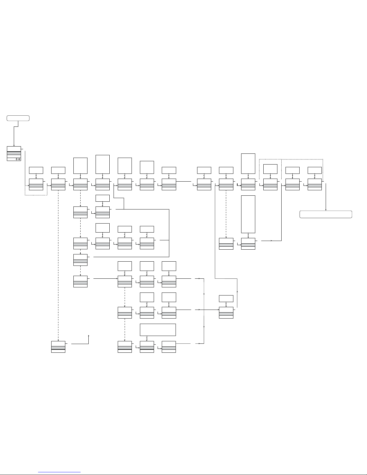
Power up
0000
PASSW.
Txt 1
50.0
%
12.0
3
3
0000
9999
1 2
NO
ADV.SET
Txt 2
NO
YES
1 2
3
VOLT
IN TYPE
Txt 3
VOLT
CURR
LIN.R
POTM
TEMP
1 2
3
2-10
V.RANGE
Txt 4
2-10
0-10
1-5
0-5
0.2-1
0-1
1 2
3
CURR
IN TYPE
Txt 3
3
4-20
I.RANGE
Txt 5
0-20
4-20
1 2
3
LIN.R
IN TYPE
Txt 3
3
3W
CONNEC.
Txt 6
4W
3W
2W
1 2
3
POTM
IN TYPE
Txt 3
3
TEMP
IN TYPE
Txt 3
0
R 0%
Txt 7
0000
9999
1 2
3
2500
R 100%
Txt 8
0000
9999
1 2
3
Pt
SENSOR
Txt 10
Pt
NI
TC
1 2
3
YES
ADV.SET
Txt 2
3
Ni
SENSOR
Txt 10
3
TC
SENSOR
Txt 10
3
100
Pt TYPE
Txt 16
1000
-
10
1 2
3
3W
CONNEC.
Txt 6
4W
3W
2W
1 2
100
Ni TYPE
Txt 17
1000
-
50
1 2
3
3W
CONNEC.
Txt 6
4W
3W
2W
1 2
TC.K
TC.TYPE
Txt 18
TC.B TC.E TC.J TC.K
TC.L TC.N TC.R TC.S
TC.T TC.U TC.W3 TC.W5
TC.Lr
1 2
0.0
DISP.LO
Txt 13
999.9
-199.9
1 2
3
111.1
DEC.P
Txt 12
1111
111.1
11.11
1.111
1 2
3
UNIT
%
Txt 11
@C
mA
rpm
(69 units)
1 2
3
100.0
DISP.HI
Txt 14
999.9
-199.9
1 2
3 3
1.1
CURR
ANA.OUT
Txt 36
VOLT
CURR
1 2
3
4-20
O.RANGE
Txt 37
S20-4
20-4
20-0
S4-20
4-20
0-20
1 2
3
Volt
ANA.OUT
Txt 36
3
0-10
O.RANGE
Txt 39
10-2
10-0
5-1
5-0
1-0.2
1-0
2-10
0-10
1-5
0-5
0.2-1
0-1
1 2
3
23mA
OUT.ERR
Txt 38
23mA
0/3.5mA
NONE
1 2
3
0.0
OUT.LO
Txt 41
4172
-328
1 2
3
150.0
OUT.HI
Txt 42
4172
-328
1 2
1.2
1.3 1.3
3
1.0
3
3
3
@C
UNIT
Txt 9
@C
@F
1 2
3
3
@C
@F
%
A
bar
cm
ft
ft/h
ft/min
ft/s
g
gal/h
gal/min
GW
hp
hPa
Hz
in
in/h
in/min
in/s
ips
K
kA
kg
kJ
kPa
kV
kW
kWh
l
l/h
l/min
l/s
m
m/h
m/min
m/s
m/s2
m3
m3/h
m3/min
mA
mbar
mils
min
mm
mm/s
mol
MPa
mV
MW
MWh
N
Ohm
Pa
pH
rpm
s
S
t
t/h
uA
um
uS
V
W
Wh
yd
[blank]
3
INT
CJC
Txt 63
92
93
Flussdiagramm
Wenn für eine Dauer von 1 Minute keine Taste betätigt wird, kehrt das
Display auf den Menüpunkt 1.0 zurück und eventuelle Änderungen in
der Konfiguration werden nicht gespeichert.
1 Wert erhöhen / nächsten Parameter wählen
2 Wert herabsetzen / vorheringen Parameter Wählen
3 Parameter speicher und nächsten Parameter wählen
Halten 3 Zurück zum vorheringen Parameter / zurück zum Menüpunkt
1.0 ohne Speicherung von Änderungen
1.0 = Normal-Zustand
Zeile 1 zeigt das
Eingangssignal an.
Zeile 2 zeigt die
Einheiten an.
1 und 2 gleich zeitig drücken:
Zeile 3 schaltet
zwischen A.Out
oder TAG.
Zeile 4 zeigt den
Kommunikations status an.
1.1 = Nur wenn durch
Passwort gesichert.
1.2 = Nicht gültig für
folgende Ein gangssignale:
0...20 mA und
Spannung.
1.3 = Nur wenn
Eingangssignal
Temperatur.
Fortsetzung auf Seite 93
Flussdiagramm ADV.SET
Zum Normal-Zustand 1.0
Wählbare EINHEITEN:
Page 49
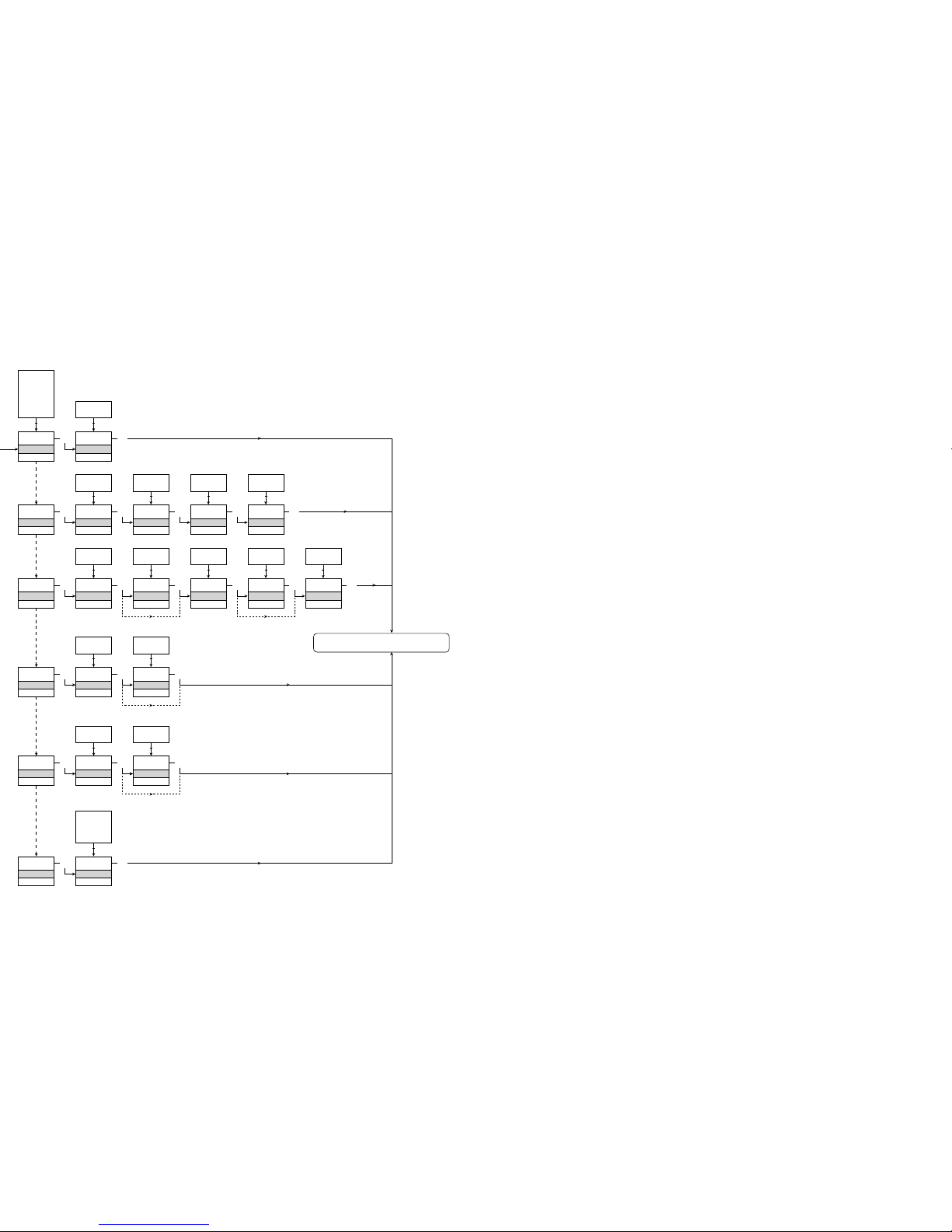
SAVE
MEMORY
Txt 44
3
SAVE
LOAD
1 2
MEM
SETUP
Txt 43
MEM
DISP
CAL
SIM
PASS
LANG
1 2
3
DISP
SETUP
Txt 43
3
3
CONTRA
Txt 45
3
9
0
1 2
9
LIGHT
Txt 46
3
9
0
1 2
VALVE 5
Txt 47
3
9
A
1 2
A.OUT
LINE 3
Txt 48
3
TAG
A.OUT
1 2
CAL
SETUP
Txt 43
3
YES
CAL.LO
Txt 49
3
YES
NO
1 2
2.0
%
Txt 61
3
100.0
0.0
1 2
NO
YES
CAL.HI
Txt 50
3
YES
NO
1 2
90.0
%
Txt 62
3
100.0
0.0
1 2
NO
YES
USE.CAL
Txt 60
3
YES
NO
1 2
SIM
SETUP
Txt 43
3
YES
EN.SIM
Txt 51
3
YES
NO
1 2
25.0
%
Txt 52
3
100.0
0.0
1 2
NO
PASS
SETUP
Txt 43
3 3
YES
EN.PASS
Txt 54
3
YES
NO
1 2
0000
NEW.PAS
Txt 55
3
9999
0000
1 2
LANG
SETUP
Txt 43
3
UK
LANGUA
Txt 59
3
DE, DK,
ES, FR,
IT, SE,
UK
1 2
2.0
NO
94
95
[01]
[02]
[03]
[04]
[05]
[06]
[07]
[08]
[09]
[10]
[11]
[12]
[13]
[14]
[16]
[17]
[18]
[36]
[37]
[38]
[39]
[41]
[42]
[43]
[44]
[45]
[46]
[47]
[48]
[49]
[50]
[51]
[52]
[54]
[55]
[59]
[60]
[61]
[62]
[63]
Einstellung des korrekten Passwortes
Eingabe erweitertes Setup Menü?
Auswahl Temperatur-Eingang
Auswahl Potentiometer-Eingang
Auswahl linearer Widerstandseingang
Auswahl Stromeingang
Auswahl Spannungseingang
Wähle 0.0-1 V Eingangsbereich
Wähle 0,2-1 V Eingangsbereich
Wähle 0-5 V Eingangsbereich
Wähle 1-5 V Eingangsbereich
Wähle 0-10 V Eingangsbereich
Wähle 2-10 V Eingangsbereich
Wähle 0-20 mA Eingangsbereich
Wähle 4-20 mA Eingangsbereich
Wähle 2-Leiter Sensoranschluss
Wähle 3-Leiter Sensoranschluss
Wähle 4-Leiter Sensoranschluss
Einstellung unterer Widerstandswert
Einstellung oberer Widerstandswert
Wähle Celsius als Temperatureinheit
Wähle Fahrenheit als Temperatureinheit
Wähle TC Sensor Typ
Wähle Ni Sensor Typ
Wähle Pt Sensor Typ
Wähle Display Einheit
Wähle Dezimalpunkt Position
Einstellung unterer Displaybereich
Einstellung oberer Displaybereich
Wähle Pt10 als Sensor Typ
Wähle Pt20 als Sensor Typ
Wähle Pt50 als Sensor Typ
Wähle Pt100 als Sensor Typ
Wähle Pt200 als Sensor Typ
Wähle Pt250 als Sensor Typ
Wähle Pt300 als Sensor Typ
Wähle Pt400 als Sensor Typ
Wähle Pt500 als Sensor Typ
Wähle Pt1000 als Sensor Typ
Wähle Ni50 als Sensor Typ
Wähle Ni100 als Sensor Typ
Wähle Ni120 als Sensor Typ
Wähle Ni1000 als Sensor Typ
Wähle TC-B als Sensor Typ
Wähle TC-E als Sensor Typ
Wähle TC-J als Sensor Typ
Wähle TC-K als Sensor Typ
Wähle TC-L als Sensor Typ
Wähle TC-N als Sensor Typ
Wähle TC-R als Sensor Typ
Wähle TC-S als Sensor Typ
Wähle TC-T als Sensor Typ
Wähle TC-U als Sensor Typ
Wähle TC-W3 als Sensor Typ
Wähle TC-W5 als Sensor Typ
Wähle TC-Lr als Sensor Typ
Auswahl Strom als Analogausgang
Auswahl Spannung als Analogausgang
Auswahl 0-20 mA Ausgangsbereich
Auswahl 4-20 mA Ausgangsbereich
Auswahl S4-20 mA mit Sicherheitsüberwachung
Auswahl 20-0 mA Ausgangsbereich
Auswahl 20-4 mA Ausgangsbereich
Auswahl S20-4 mA mit Sicherheitsüberwachung
Scrollender Hilfetext im Display Zeile 3
Auswahl keine Fehlererkennung - Ausgang undefiniert
bei Fehler
Wähle Downscale bei Fehler
Wähle NAMUR NE43 Downscale bei Fehler
Wähle NAMUR NE43 Upscale bei Fehler
Auswahl 0.0-1 V Ausgangsbereich
Auswahl 0,2-1 V Ausgangsbereich
Auswahl 0-5 V Ausgangsbereich
Auswahl 1-5 V Ausgangsbereich
Auswahl 0-10 V Ausgangsbereich
Auswahl 2-10 V Ausgangsbereich
Auswahl 1-0,0 V Ausgangsbereich
Auswahl 1-0,2 V Ausgangsbereich
Auswahl 5-0 V Ausgangsbereich
Auswahl 5-1 V Ausgangsbereich
Auswahl 10-0 V Ausgangsbereich
Auswahl 10-2 V Ausgangsbereich
Einstellung Temperatur für Analogausgang LOW
Einstellung Temperatur für Analogausgang HIGH
Eingabe Passwort Einstellung
Eingabe Simulationsmodus
Prozesskalibrierung ausführen
Eingabe Display Setup
Memory Operationen Ausführen
Lade gespeicherte Konfiguration in das 4114
Speicher 4114 Konfiguration im 4501
Einstellung LCD Kontrast
Einstellung LCD Hintergrundbeleuchtung
Schreibe eine 6-Zeichen Geräte TAG Nummer
Analoge Ausgangswert wird in Zeile 3 angezeigt
Geräte TAG wird im Zeile 3 des Displays angezeigt
Kalibriere Input Low zum Prozesswert
Kalibriere Input High zum Prozesswert
Ermögliche Simulationsmodus
Setze den Eingangs- Simulationswert
Ermögliche Passwortschutz
Eingabe eines neuen Passworts
Wähle Sprache
Verwende Prozesskalibrierungswerte?
Eingabe des Wertes für den unteren Kalibrierungspunkt
Eingabe des Wertes für den oberen Kalibrierungspunkt
Auswahl interner Temperatur Sensor
Auswahl CJC-Klemme (Zubehör)
Flussdiagramm
Erweiterte Einstellungen (ADV.SET)
Zum Normal-Zustand 1.0
2.0 Im Untermenü Simulation (SIM) muss 3
betätigt werden um auf den Menüpunkt 1.0
zurückzukehren.
Page 50
PR electronics A/S tilbyder et bredt program af analoge og digitale
signalbehandlingsmoduler til industriel automation. Programmet
består af Isolatorer, Displays, Ex-barrierer, Temperaturtransmittere,
Universaltransmittere mfl. Vi har modulerne, du kan stole på i selv
barske miljøer med elektrisk støj, vibrationer og temperaturudsving,
og alle produkter opfylder de strengeste internationale standarder.
Vores motto »Signals the Best« er indbegrebet af denne filosofi –
og din garanti for kvalitet.
PR electronics A/S offers a wide range of analogue and digital
signal conditioning modules for industrial automation. The product
range includes Isolators, Displays, Ex Interfaces, Temperature
Transmitters, and Universal Modules. You can trust our products
in the most extreme environments with electrical noise, vibrations
and temperature fluctuations, and all products comply with the
most exacting international standards. »Signals the Best« is the
epitome of our philosophy – and your guarantee for quality.
PR electronics A/S offre une large gamme de produits pour le
traite ment des signaux analogiques et numériques dans tous
les domaines industriels. La gamme de produits s’étend des
transmetteurs de température aux afficheurs, des isolateurs aux
interfaces SI, jusqu’aux modules universels. Vous pouvez compter
sur nos produits même dans les conditions d’utilisation sévères,
p.ex. bruit électrique, vibrations et fluctuations de température.
Tous nos produits sont conformes aux normes internationales les
plus strictes. Notre devise »SIGNALS the BEST« c’est notre ligne
de conduite - et pour vous l’assurance de la meilleure qualité.
PR electronics A/S verfügt über ein breites Produktprogramm
an analogen und digitalen Signalverarbeitungsmodule für die industrielle Automatisierung. Dieses Programm umfasst Displays,
Temperaturtransmitter, Ex- und galvanische Signaltrenner, und
Universalgeräte. Sie können unsere Geräte auch unter extremen
Einsatzbedingungen wie elektrisches Rauschen, Erschütterungen
und Temperaturschwingungen vertrauen, und alle Produkte von
PR electronics werden in Überein stimmung mit den strengsten
internationalen Normen produziert. »Signals the Best« ist Ihre
Garantie für Qualität!
DK
UK
FR
DE
Head office
Denmark www.prelectronics.com
PR electronics A/S [email protected]
Lerbakken 10 tel. +45 86 37 26 77
DK-8410 Rønde fax +45 86 37 30 85
Subsidiaries
France
PR electronics Sarl
Zac du Chêne, Activillage
4, allée des Sorbiers
F-69673 Bron Cedex
Germany
PR electronics GmbH
Im Erlengrund 26
D-46149 Oberhausen
Italy
PR electronics S.r.l.
Via Giulietti 8
IT-20132 Milano
Spain
PR electronics S.L.
Avda. Meridiana 354, 9°
B
E-08027 Barcelona
Sweden
PR electronics AB
August Barks gata 6A
S-421 32 Västra Frölunda
UK
PR electronics UK Ltd
Middle Barn, Apuldram
Chichester
West Sussex, PO20 7FD
USA
PR electronics Inc
11225 West Bernardo Court
Suite A
San Diego, California 92127
[email protected]
tel. +33 (0) 4 72 14 06 07
fax +33 (0) 4 72 37 88 20
[email protected]
tel. +49 (0) 208 62 53 09-0
fax +49 (0) 208 62 53 09 99
[email protected]
tel. +39 02 2630 6259
fax +39 02 2630 6283
[email protected]
tel. +34 93 311 01 67
fax +34 93 311 08 17
[email protected]
tel. +46 (0) 3149 9990
fax +46 (0) 3149 1590
[email protected]
tel. +44 (0) 1243 776 450
fax +44 (0) 1243 774 065
[email protected]
tel. +1 858 521 0167
fax +1 858 521 0945
 Loading...