

Page 1
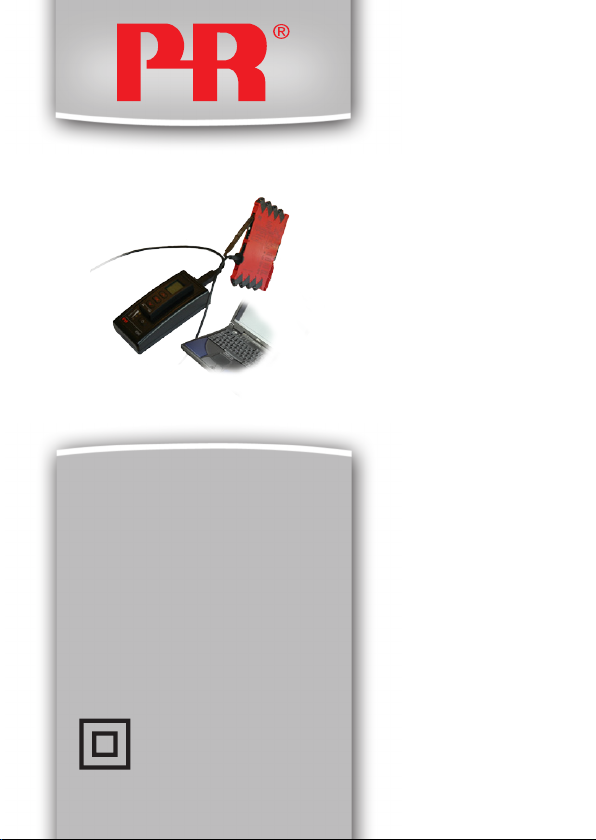
4 5 9 0
C o n f i g M a t e
U S B C o m m u n i c a t i o n s
I n t e r f a c e
N o . 4 5 9 0 V 1 0 0 - I N
F r o m s e r . n o . 1 1 0 4 0 4 0 0 1
S I G N A L S T H E B E S T
Page 2

DK
PR electronics A/S tilbyder et bredt program af analoge og digitale
signalbehandlingsmoduler til industriel automation. Programmet
består af Isolatorer, Displays, Ex-barrierer, Temperaturtransmittere,
Universaltransmittere mfl. Vi har modulerne, du kan stole på i selv
barske miljøer med elektrisk støj, vibrationer og temperaturudsving, og alle produkter opfylder de strengeste internationale standarder. Vores motto »Signals the Best« er indbegrebet af denne
filosofi – og din garanti for kvalitet.
UK
PR electronics A/S offers a wide range of analogue and digital
signal conditioning devices for industrial automation. The product
range includes Isolators, Displays, Ex Interfaces, Temperature
Transmitters, and Universal Devices. You can trust our products
in the most extreme environments with electrical noise, vibrations
and temperature fluctuations, and all products comply with the
most exacting international standards. »Signals the Best« is the
epitome of our philosophy – and your guarantee for quality.
FR
PR electronics A/S offre une large gamme de produits pour le
traite ment des signaux analogiques et numériques dans tous
les domaines industriels. La gamme de produits s’étend des
transmetteurs de température aux afficheurs, des isolateurs aux
interfaces SI, jusqu’aux modules universels. Vous pouvez compter
sur nos produits même dans les conditions d’utilisation sévères,
p.ex. bruit électrique, vibrations et fluctuations de température.
Tous nos produits sont conformes aux normes internationales les
plus strictes. Notre devise »SIGNALS the BEST« c’est notre ligne
de conduite - et pour vous l’assurance de la meilleure qualité.
DE
PR electronics A/S verfügt über ein breites Produktprogramm
an analogen und digitalen Signalverarbeitungsmodule für die industrielle Automatisierung. Dieses Programm umfasst Displays,
Temperaturtransmitter, Ex- und galvanische Signaltrenner, und
Universalgeräte. Sie können unsere Geräte auch unter extremen
Einsatzbedingungen wie elektrisches Rauschen, Erschütterungen
und Temperaturschwingungen vertrauen, und alle Produkte von
PR electronics werden in Überein stimmung mit den strengsten
internationalen Normen produziert. »Signals the Best« ist Ihre
Garantie für Qualität!
11 20
Page 3

USB COMMUNICATIONS INTERFACE
CONFIGMATE 4590
CONTENTS
Warning .............................................................................. 2
Safety instructions .............................................................. 4
Application ......................................................................... 6
Docking Mode ................................................................ 6
Adaptor Mode ................................................................ 8
USB and PReset installation (Docking Mode Only) ........... 9
Technical characteristics ................................................ 9
System requirements ..................................................... 9
Installation of USB driver for Windows® XP ................. 10
Installation of USB driver for Windows® Vista .............. 13
Installation of USB driver for Windows® 7 .................... 16
Installation of PReset ..................................................... 18
459 0 V 100- I N 1
Page 4
GENERAL
CONTENTS
EXPLO-
SION
ELECTRICAL
SHOCK
This device is designed for connection to hazardous electric
WARNING
voltages. Ignoring this warning can result in severe personal
injury or mechanical damage.
To avoid the risk of electric shock and fire, the safety instructions
and warnings of this guide must be observed and the guidelines
followed. The specifications must not be exceeded, and the
device must only be applied as described in the following.
Prior to the commissioning of the device, this guide must be
examined carefully.
Only qualified personnel (technicians) should operate this device.
If the equipment is used in a manner not specified by the
manufacturer, the protection provided by the equipment may be
impaired.
Repair of the device must be done by PR electronics A/S only.
Should there be any doubt as to the correct handling of the
device, please contact your local distributor or, alternatively, PR
electronics A/S.
WARNING RISK OF EXPLOSION HAZARD
To avoid risk of explosion and injury:
• Do not use this equipment when a flammable or
combustible atmosphere is present
• Do not replace batteries unless area is known to be safe.
• Use 3 x 1.5V TYPE AAA Batteries only and insert correct
as stipulated in battery compartment.
WARNING RISK OF ELECTRICAL SHOCK
To avoid risk of electrical shock and injury:
• Do not disconnect the cable from ConfigMate 4590 while
cable is connected to a SYSTEM 3000 device.
• Do not remove 4501 while the cable is connected to a
SYSTEM 3000 device.
• Do not replace batteries while the cable is connected to a
SYSTEM 3000 device.
2 4590V10 0 - IN
Page 5
SYMBOL IDENTIFICATION
CONTENTS
Triangle with an exclamation mark: Warning/demand. Potentially lethal
situations.
The CE mark proves the compliance of the device with the
requirements of the EU directives.
The double insulation symbol shows that the device is protected by
double or reinforced insulation.
459 0 V 100- I N 3
Page 6

SAFETY INSTRUCTIONS
CONTENTS
DEFINITIONS
Hazardous voltages have been defined as the ranges: 75...1500 Volt DC, and
50...1000 Volt AC.
Technicians are qualified persons educated or trained to mount, operate, and
also trouble-shoot technically correct and in accordance with safety regulations.
Operators, being familiar with the contents of this manual, adjust and operate
the knobs or potentiometers during normal operation.
RECEIPT AND UNPACKING
Unpack the device without damaging it. Check on delivery of the device
whether the type corresponds to the one ordered.
ENVIRONMENT
Avoid direct sunlight, dust, high temperatures, mechanical vibrations and shock,
as well as rain and heavy moisture.
NORMAL OPERATION
Only technicians who are familiar with the technical terms, warnings, and
instructions in the manual and who are able to follow these should connect the
device.
Should there be any doubt as to the correct handling of the device, please
contact your local distributor or, alternatively,
CLEANING
When disconnected, the device may be cleaned with a cloth moistened with
distilled water.
LIABILITY
To the extent that the instructions in this manual are not strictly observed, the
customer cannot advance a demand against PR electronics A/S that would
otherwise exist according to the concluded sales agreement.
BATTERY REPLACEMENT
Replace batteries with 3 x 1.5V TYPE AAA (Not included)
PR electronics A/S
www.prelectronics.com
4 4590V10 0 - IN
Page 7

EC DECLARATION OF CONFORMITY
CONTENTS
As manufacturer
PR electronics A/S
Lerbakken 10
DK-8410 Rønde
hereby declares that the following product:
Type: 4590
Name: ConfigMate
is in conformity with the following directives and standards:
The EMC Directive 2004/108//EC and later amendments
EN 61326-1 : 2006
For specification of the acceptable EMC performance level, refer to the
electrical specifications for the device.
The Low Voltage Directive 2006/95/EC and later amendments
EN 61010-1 : 2001
Rønde, 18 May 2011 Kim Rasmussen
Manufacturer’s signature
459 0 V 100- I N 5
Page 8
Application
CONTENTS
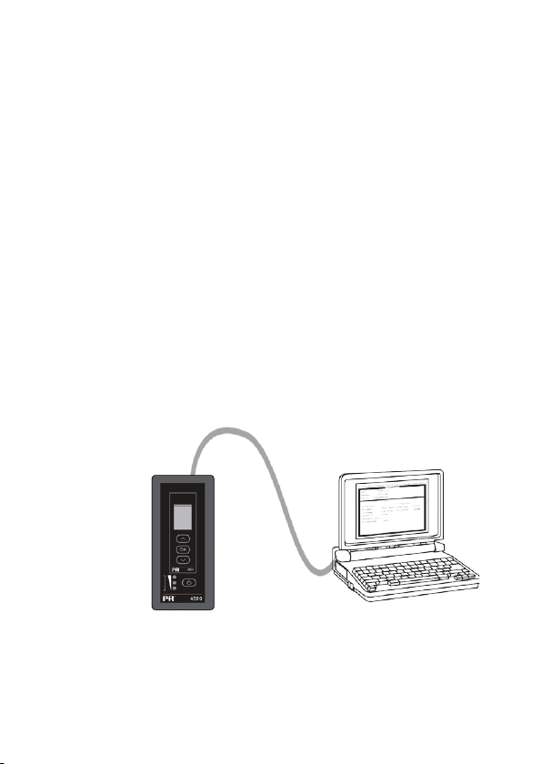
The ConfigMate 4590 is a USB communications interface which is used along
with the 4501 Programmable Display to configure or document and backup/
restore configurations of selected PR electronics’ programmable devices, either
standalone in Adaptor Mode or with a PC in Docking Mode.
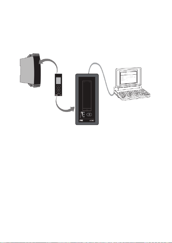
Docking Mode
o The 4590 can operate as a docking station for the 4501 allowing the
4501 to be connected to a PC through a USB interface. The PReset
software can be used to upload and download the configuration
parameters from a 4501 for backup/restore and documentation
purposes, on selected 3000, 4000 and 9000 series devices.
o Note for connection to a PC the USB-B to USB-A cable must be used
o In docking station mode the 4590 will be powered from the PC’s USB
power source; no batteries are required.
o The 4501 display will indicate USB line/communication with a very short
blink when uploading or downloading configurations from/to the 4501.
Connection of ConfigMate 4590 to a PC in Docking Mode
6 4590V10 0 - IN
Page 9
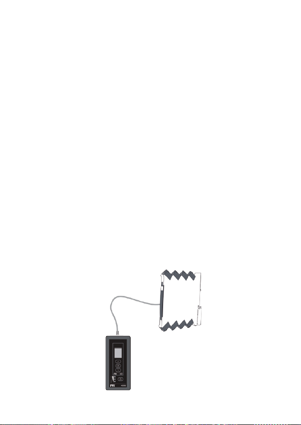
Connection of ConfigMate 4590 to a PR 4000/9000 Device
CONTENTS
Note:
By default, the Programming Display 4501 will display the desired Process
Value when connected to a device, either directly or via ConfigMate 4590.
o To upload a configuration from a 3000/4000/9000 device to the
Programming Display 4501, you must manually go into the Memory
Menu of the 4501 and SAVE from the target device into the 4501.
o To download a configuration to a 3000/4000/9000 device from the
Programming Display 4501, you must manually go into the Memory
Menu of the 4501 and LOAD to the target device from the 4501.
For further details, please refer to the relevant manual for the target device.
459 0 V 100- I N 7
Page 10
Adaptor Mode
CONTENTS
o The 4590 is a handheld device that can operate as an adapter between
the 4501 programming front and a selected modules in the 3000 series.
This allows for configuration and monitoring of process parameters of
the installed modules.
o Note for connection to a 3000 series product, the PR USB-B to a 2.5
mm jack cable must be used.
o By pressing the power button, the 4590 will power on, and show the
status of the attached 3000 module on the 4501.
o If the 3000 device is powered, the 4501 display will indicate the
Process Variable or can be manually set to go into program mode.
o If the 3000 device is not powered the 4501 display will be in
program mode only.
o Indication of battery level is displayed via the LEDs. This can be
activated by using the Power/Wake-up button. If while pressing the
Power/Wake-up button the LEDs are off, or only one LED is lit, the
batteries should be exchanged. To extend battery life the 4590 will
automatically detect if it is not in use, and will consequently shut itself
down to conserve battery power.
o Battery life in Adaptor Mode is approximately 1 year of daily use,
depending upon battery type.
Connection of ConfigMate 4590 to a PR 3000 Device
8 4590V10 0 - IN
Page 11

USB and PReset installation (Docking Mode Only)
CONTENTS
The USB communication is supported by Windows® 2000, XP, Vista and
Windows® 7. PR devices that can either be programmed or have their
configurations saved, backedup/restored via ConfigMate 4590 are available in
the configuration program PReset ver. 6.0 or higher.
Technical characteristics
The PC program PReset ver. 6.0 or higher supports ConfigMate 4590. To
conserve power on a laptop, the USB connector of the 4590 can be connected
to an externally supplied hub. The communications connector on the PR device
is galvanically isolated from the USB connection on the PC.
System requirements
Access to internet is needed for installation of USB drivers
Installation rights
Windows® 2000, XP, Vista and Windows® 7 with the following
recommendations:
Hard disk space: 25 MB
USB: Version 2.0 or higher
459 0 V 100- I N 9
Page 12
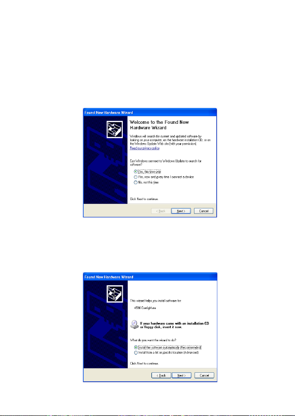
Installation of USB driver for Windows® XP
CONTENTS
To install the USB driver:
1. Connect ConfigMate 4590 to the USB port of the PC.
2. After a short while, the ”Found New hardware wizard” will appear.
Allow Windows Update to search for software by selecting “Yes, this
time only” followed by “Next”
3. Allow the Hardware Wizard to automatically install the appropriate
software drivers by selecting “Install the software automatically
(Recommended)” followed by “Next”
10 4590V10 0 - IN
Page 13
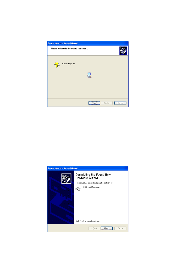
4. The Hardware Wizard will then search for the appropriate drivers
CONTENTS
5. Once the Hardware Wizard finds the USB driver it will be installed
automatically
6. After successful installation, the Hardware Wizard will indicate that
it has completed the installation with the following dialogue box.
459 0 V 100- I N 11
Page 14
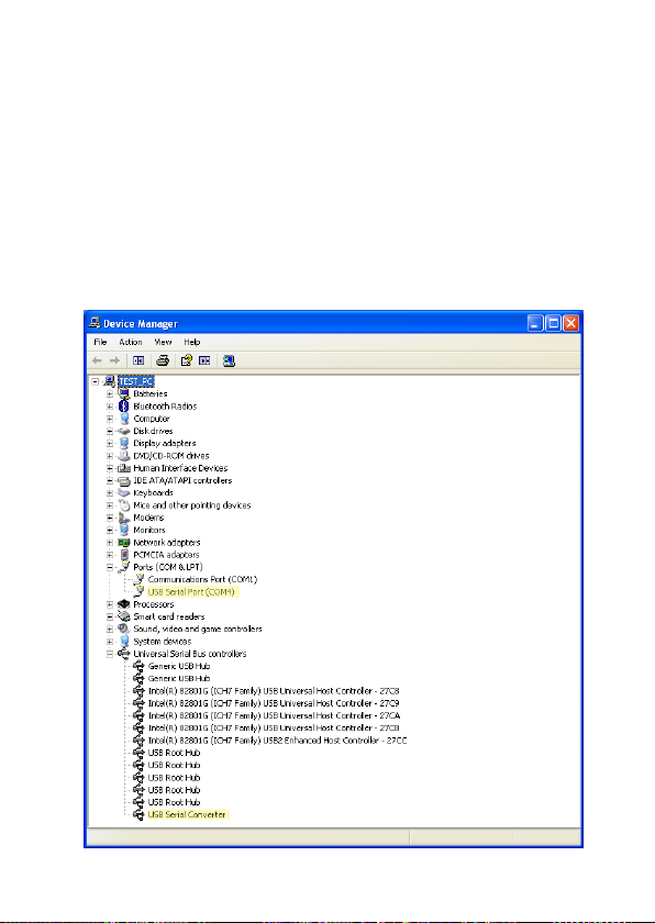
7. To check installation and allocation of the COM port, open up
CONTENTS
“Device Manager” and expand the “Ports” and “Universal Serial Bus
controller” sections. “USB Serial Port” and “USB Seial Converter”
should appear in the sections as highlighted below. The COM port
assigned is also highlighted in the “Ports” section. In the example
highlighted this was assigned COM4, however this may change
from installation to installation. Take a note of which COM port is
assigned as this is used later in the PReset software.
12 4590V10 0 - IN
Page 15
Installation of USB driver for Windows® Vista
CONTENTS
To install the USB driver:
1. Connect ConfigMate 4590 to the USB port of the PC.
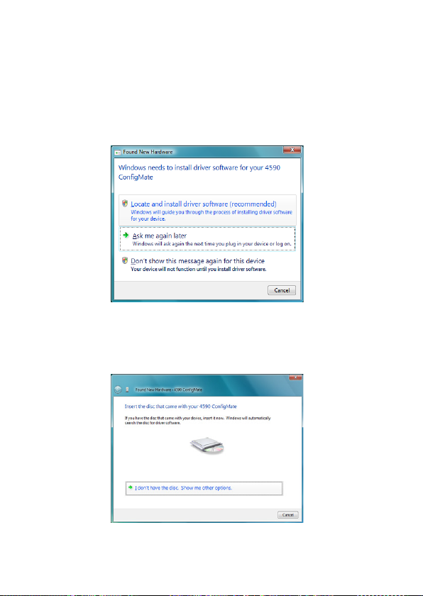
2. After a short while, the ”Found New Hardware” wizard will be
shown. Select “Locate and install driver software (recommended)”
3. The Found New Hardware dialogue box will appear. Select “I don’t
have a disc. Show me other options”
459 0 V 100- I N 13
Page 16
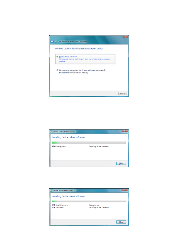
4. If Windows does not find a preconfigured driver select “Check for
CONTENTS
Solution”
5. Windows will then automatically search for, download and install the
appropriate driver
6. Windows will then install the USB Serial Convertor driver followed
by the USB Serial Port driver.
14 4590V10 0 - IN
Page 17
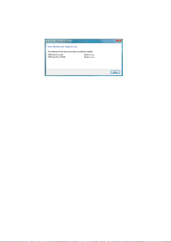
7. After successful installation, Windows will indicate that the device is
CONTENTS
“Ready to use”
8. Check installation and allocation of the COM port in the “Device
Manager” as described in the installation for XP
459 0 V 100- I N 15
Page 18
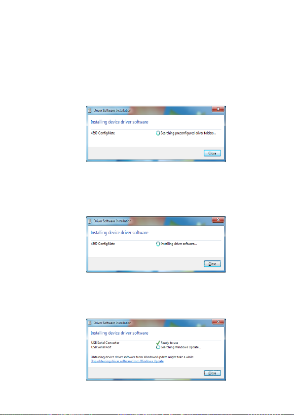
Installation of USB driver for Windows® 7
CONTENTS
To install the USB driver:
1. Connect ConfigMate 4590 to the USB port of the PC.
2. After a short while, the ”Driver Software Installation ” dialogue box
can be viewed. Windows will first automatically search the computer
for preconfigured drivers
3. Windows will then automatically search the internet for appropriate
drivers
4. Windows will then install the drivers for ConfigMate
5. Windows will then install the USB Serial Convertor followed by USB
Serial Port driver.
16 4590V10 0 - IN
Page 19
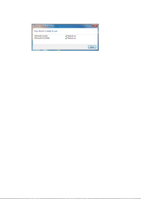
6. After successful installation, Windows will indicate that the device
CONTENTS
is” Ready to use”
7. Check installation and allocation of the COM port in “Device
Manager” as described in the installation for XP
459 0 V 100- I N 17
Page 20

Installation of PReset
CONTENTS
Before installing PReset, previous versions must first be uninstalled. During the
uninstall process there will be an option to save existing configuration files. If
this option is not accepted, then these files will be deleted during the uninstall
process.
PReset will be installed on your hard disk and the registry will be updated with
all necessary information on the program. A PReset icon will automatically be
placed on the desk top.
1. Download PReset version 6.0 or later from www.prelectronics.com.
Note that this is in the form of a zip file.
2. Unzip the file to the desired location.
3. To start the installation, double click the setup.exe file. When the
installation program has been started, on-screen guidelines will guide
you through the rest of the installation.
The following is an example of PReset installation on Windows® 7
Note: To install PReset on Windows 7 it is necessary to be a local administrator
on the PC.
18 4590V10 0 - IN
Page 21
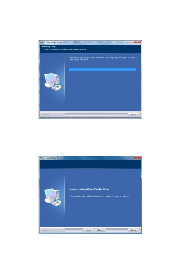
1. PReset Setup will prepare the Installation Wizard on double clicking
CONTENTS
setup.exe
2. Installation Wizard will appear, click “Next” to start the installation
3. InstallShield Wizard for PReset will appear, press “Next “ to continue
459 0 V 100- I N 19
Page 22
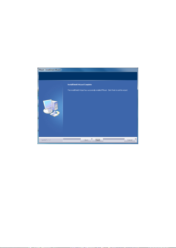
4. Read and accept the License Agreement and press “Next “ to continue
CONTENTS
5. Chose the destination for the installation and press “Next “ to continue
6. Installation will then be ready to proceed, select “Install” to continue.
7. The installation of PReset will then continue
8. When installation is complete click “Finish” to exit.
20 4590V10 0 - IN
Page 23
Displays
selection of inputs and outputs for display of temperature,
volume and weight, etc. Feature linearisation, scaling,
and difference measurement functions for programming
via PReset software.
Ex interfaces
signals as well as HART® signals between sensors / I/P
converters / frequency signals and control systems in Ex
zone 0, 1 & 2 and for some modules in zone 20, 21 & 22.
Programmable displays with a wide
Interfaces for analogue and digital
Isolation
digital signals as well as HART® signals. A wide product
range with both loop-powered and universal isolators
featuring linearisation, inversion, and scaling of output
signals.
Temperature
form B mounting and DIN rail modules with analogue
and digital bus communication ranging from applicationspecific to universal transmitters.
Universal
universal options for input, output and supply. This range
offers a number of advanced features such as process
calibration, linearisation and auto-diagnosis.
Galvanic isolators for analogue and
A wide selection of transmitters for DIN
PC or front programmable modules with
Page 24
www.prelectronics.fr
[email protected]
www.prelectronics.de
[email protected]
www.prelectronics.es
[email protected]
www.prelectronics.it
[email protected]
www.prelectronics.se
[email protected]
www.prelectronics.co.uk
[email protected]
www.prelectronics.com
[email protected]
www.prelectronics.org.cn
[email protected]
Head office
Denmark www.prelectronics.com
DK-8410 Rønde fax +45 86 37 30 85
 Loading...