


Operating Manual for
UMD 701
Short version 2.0
Contents
1
General Description 1
2
Operating the Meter 2
2.1 Safety requirements when using UMD 701
2.2 Installation of the instrument
2.2.1 Supply voltage
2.2.2 Measured voltage
2.2.3 Measured currents
2.2.4 Communication peripherals
2.2.5 Outputs and inputs
2.3 Downloading data to PC
2.4 Energy meter readings
..................................................................................................................................
.........................................................................................................................................
..................................................................................................................
..............................................................................................................................
...................................................................................................................................
..............................................................................................................
.....................................................................................................................
........................................................................................................................
...................................................................................................
2
3
3
3
4
4
5
6
6
3
Technical Specifications 7
3.1 Basic Parameters
3.2 Measured Quantities
4
Maintenance, Service, Warranty 11
..................................................................................................................................................
....................................................................................................................................
7
8

1
1 General Description
The UMD 701 is specially designed for monitoring of energy and power quality in advanced power systems and
smart grids. It is intended to be used mostly for DIN rail mounting. This display-less design with multiple
communication options is suitable for a wide spectrum of automation tasks in modern buildings, distributed
power generation, remote supervision of the infrastructure and also remote load management. Absence of local
panel controls (display and keyboard) limits possibilities for hostile user interaction. To protect the actual
setup and collected data each instrument can be locked by a custom pin. Inputs and outputs can be custum
programmed for basic local control applications. It uses standard RS-485 serial line for communication with
remote control systems. Optionally it can be equipped with other communication peripherals such as secondary
RS-485 or M-Bus communication line, or USB, WiFi and Ethernet interface.
It is equipped with one voltage input and two, four or eight current inputs. The instrument can be also
supplied with for current transformers with X/100 mA ratio, for special Hall probes (to measure DC or AC+DC
currents) with ➧4 V output, or Sxxx and Pxxx option for external through-hole or clamp-on current sensors for
direct measuring up to 2400 A nominal current according to the type of the current transformer.
Warning !
The X/100mA, Sxxx and Pxxx, X/➧4 V options are specially designed to be used only in
combination with provided external current sensors which are supported with the respective option.
The UMD 701 is available in several configurations according to the customer requirements1. See the ordering
scheme on figure 1.
1
Complete and most up to date list of optional and other accessories are available on request from the device vendor.

2
Instrument model
UMD = Universal Meassering Device
Measuring inputs
1 voltage + 8 current inputs
Auxiliary power supply
U = 75 V ÷ 275 VAC, 75 V ÷ 35O VDC
Current inputs
X/1OOmA = 1OOmA AC (indirect measurement
Optional digital output
pulse output
Optional peripheral
two digital inputs
Optional expanding module
E = Ethernet interface
UMD 701
Figure 1: Schematics of the UMD 701 ordering options and variants. It includes special codes for proper current
and voltage rating options.
2 Operating the Meter
2.1 Safety requirements when using UMD 701
Warning !:
protection of persons and property against injury and electric shock.
❼
The device must be operated by a person with all required qualifications for such work and this person
must know in detail the operation principles of the equipment listed in this description!
❼
When the device is being connected to the parts which are under dangerous voltage it is necessary to comply
When working with the instrument it is necessary to perform all necessary measures for the
with all the necessary measures to protect users and equipment against injury with electrical shock.
❼
Person, performing the installation or maintenance of the instrument must be equipped with and must use
personal protective clothing and tools.
❼
If the analyzer is used in a manner not specified by the manufacturer, the protection provided by the
analyzer may be impaired.
3
58
21.5 10
60.6
30.3
106
UMD
UMD 701
X/4V
001
03
2014
99.8
90
45
62
❼
If the analyzer or its accessories appear to be impaired or not functioning properly, do not use it and send
it in for repair.
2.2 Installation of the instrument
Natural air circulation should be provided inside the distribution board cabinet, and in the instrument’s neighborhood. Especially underneath the instrument, no other instrumentation that is source of heat should be installed
or the temperature value measured may be influenced. A connection
2
mm
in case of all screw terminals.
wire’s
maximum cross section area is 2.5
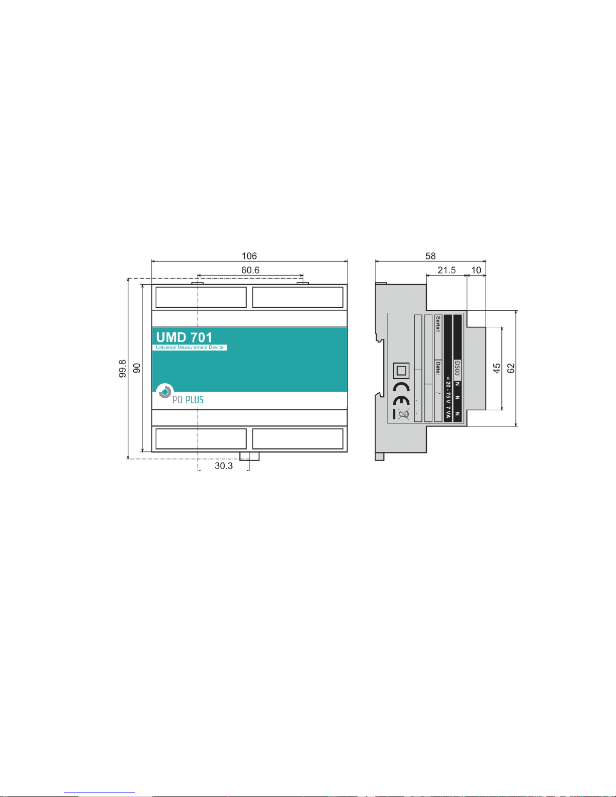
The UMD 701 is primarily intended for DIN-rail mounting. Dimensions of the instrument are on figure 2.
There are also positions marked with dash dot lines of holes for wall-mounting with three screws.
Figure 2: Dimensions of the UMD 701 analyzer.
2.2.1 Supply voltage
Power supply voltage (options in ch. 3) must be connected to the terminals X1 and X2 via a circuit breaking
device (power switch – see installation diagram on figure 3). It has to be located left to the instrument and
reachable by the operator. The circuit breaking device must be identified as the equipment power disconnection
switch. A circuit breaker of the nominal value 1 A is a convenient circuit breaking device. Its function and
position has to be clearly identified (symbols
galvanically isolated from internal circuits.
2.2.2 Measured voltage
The measured voltage is connected to the terminal L1. Connect the neutral wire to the terminal N. Voltage
measurement inputs are connected with internal circuits over high impedance.
It is suitable to protect the measured voltage lines for example with 1A fuses of the required rating. Measured
voltages can also be connected via instrument voltage transformers. A connection cable maximum cross section
area is 2.5
2
mm
for voltage terminals.
‘0’
and
‘I’
acc. to IEC EN 61010-1). Internal power supply is

4
L
N
X/4V
X/4V
X1 S X2
O- DO O+
R A1 A2 G B- A+ G2 B- A+
X1 L X2
O- DO O+
R A1 A2 G B- A+ G2 B- A+
X1 L X2 O- DO O+
R A1 A2 G B- A+ G2 B- A+
C I1 I2 I3 I4 I5 I6 I7 I8
+15 -15
C I1 I2
C I1 I2 I3 I4
N
L
JSxJSxxxHS
-xxxxxx
JSxJSxxxHS
-xxxxxx
JSxJSxxxHS
-xxxxxx
USB
Figure 3: An example of typical installation of UMD 701 instrument in a low voltage network — left to right:
with low voltage supply voltage (possible DC, AC including battery backed UPS setups); with supply from
measured network. Option E for Ethernet port remote communication, option U for local USB communication
port (all instruments provide RS485 serial line).
2.2.3 Measured currents
For proper current measuring the current sensors must be installed with correct orientation and polarity. Figure 3
illustrates such a connection of various current transformers in LV network. Intended direction of power flow
is from left (source) to right (load). It is highly recommended to verify correctness of wiring and polarity of
currents with phasor diagram in Actual Data window ot the EnVis.Daq application.
The current inputs are directly connected with internal circuits. Inputs I1,I2,..,I8 and C are connected through
shunt resistors (or divider in case of X/4V option). A connection cable maximum cross section area is 2.5
Warning !: Current inputs can not be used for dirrect current measurement. Connection of
unsupported type of current transformer such as the common type with 5A or 1A secondary to
an instrument is strictly forbidden! The instrument can be seriously damaged!
Warning !: Do not connect the current input signals with neither ground nor other potential!
Otherwise, measurement accuracy can be affected or the instrument can be damaged!
Always use only correctly rated measurement current transformers (such as ➧X mA or ➧4V) which were
originally supplied with the actual instrument.
2.2.4 Communication peripherals
All peripherals stated below are galvanically isolated from the rest of the instrument and from each other.
USB (optional)
intended for easy local configuration and fast download of archived data to the local PC. Use the supplied USB
communication port for USB slave is located on the front panel. This communication port is
2
mm
.

5
Figure 4: Typical wiring of the RS-485 communication line terminals in UMD 701 or optional M-Bus (right).
cable only (USB-A/mini). UMD 701 is a USB 2.0 slave device. For correct operation it needs a driver installed
in your operating system (see the EnVis user guide for more info).
Ethernet interface (optional)
on a top panel of the device. Ethernet interface can be used as substitution for the primary RS-485 for connection
of the device to LAN and for easy connection of remote control PC.
10Base-T Ethernet interface with RJ-45 connector described
RS-485 serial line
device configuration. Serial RS-485 line uses terminals A+,
4). The end point of the communication line must be properly terminated with ˜120n resistor.
serves usually as a remote communication for reading of actual data, archive downloading and
B-
Secondary RS-485 (optional)
display unit. Secondary RS-485 line uses terminals A+,
The final points of the communication line have to be fitted with terminating resistor approx. 120n.
communication line serves for connection of external I/O modules or remote
B-
with shielding at terminal
M-Bus interface (optional)
M-Bus implementation is described in a standalone
uses terminals
M1
and
M2
of
provides predefined measured values to the remote M-Bus control system. the
Communication Protocol Mbus
COM2
block on fig. 4 (right). Polarity of the connection is free to choose.
with shielding at terminal G of
G2
of
COM2
manual. Its physical interface
ETH
COM1
is situated
block (fig.
block (fig. 4).
2.2.5 Outputs and inputs
Digital Inputs
terminal,
input
right there is a sample schema for connection of two external switches in series with voltage source of 24 V
Digital Output
(24 V
comply with terminal poles (see fig. 5).
D1
D1
or
is recommended). In case of solid state based DO outputs an external voltage supply polarity must
DC
DI1 and DI2, sensitive to voltage, are using three terminals in
is first and
D2
is evaluated as inactive state, voltage greater than 10 V is evaluated as active state. On fig. 5
D2
connected through terminals
DI
block —
is second digital input. Voltage lower than 3 V applied between
O+
and O-. There must be an external voltage source in series
DI
is common
DI
and digital
DC
.

6
Relay Output
Digital Output
Digital Inputs
Figure 5: An example of wiring connection for inputs and outputs in UMD 701 .
2.3 Downloading data to PC
Connect the instrument to the PC and run EnVis.Daq application. Select the appropriate communication
option and connect to the instrument. In the next screen press
status of each supported archive.
Device Information
Time Frame for Other Archives
main archive. In the
the file. The check boxes in
The actual download will start by pressing the
finished the archive can be viewed in the EnVis application. User can open the downloaded file directly from
EnVis.Daq.
section contains editable description and name under which the actual record is stored.
Destination
tab allows you to limit the date ranges of all archives by the time interval of the
section the actual storage can be selected - either to the SQL database or to
Archives to Download
Download All
determines which specific archive(s) you want to download.
2.4 Energy meter readings
UMD 701 has an embedded four-quadrant energy meter with automatic meter reading functions and multiple
programmable tariffs (Time-of-Use, TOU). The instrument registers active energy (EP, EP+, EP-) and reactive
energy (EQL, EQC or EQC+, EQC-, EQL+, EQL-). According to the configuration of meter readings are
shuffled to the respective tariffs. It automatically provides summaries per phase. For star connections and single
phase measurements it can also register energy for each phase separately.
Meter data readings can be downloaded and analyzed in EnVis or via the standard ModBus protool in any
other system.
Refresh All
button. progress is displayed on screen. When
. This will load and display the actual

7
Other Specifications
operational temperature
- 20 to 60°C
storage temperature
- 40 to 80°C
operational and storage humidity
< 95 % - non-condensable environment
EMC – immunity
EN 61000 – 4 - 2 (4 kV / 8 kV)
EN 61000 – 4 - 3 (10 V/m up to 1 GHz)
EN 61000 – 4 - 4 (2 kV)
EN 61000 – 4 - 5 (2 kV)
EN 61000 – 4 - 6 (3 V)
EN 61000 – 4 - 11 (5 periods)
EMC – emissions
EN 55011, class A
EN 55022, class A (not for home use)
communication ports
RS-485 (1200 ÷ 921600 Bd), optional USB, Ethernet 10Base-T, M-bus
communication protocols
PQ PLUS, Modbus RTU and TCP, web server, DHCP
accuracy of RTC
± 2 seconds per day
capacity of RTC backup battery
> 5 years (without supply voltage applied)
protection class
front panel whole
instrument
IP 40
IP 20
dimensions
front panel
whole instrument
106 x 45 mm
106 x 90 x 58 mm
weight
max. 0.25 kg
Auxiliary Voltage
10.01.6004
10.01.8004
AC aux. voltage range, f: 40÷450 Hz
85 ÷ 275 VAC
20 ÷ 50 VAC
DC aux. voltage range
80 ÷ 350 VDC
20 ÷ 75 VDC
power supply
14 VA / 6 W
overvoltage category
III
pollution degree
2
connection
isolated, polarity free
3 Technical Specifications
3.1 Basic Parameters
AUX
Ostatni

8
Measured Quantities – Voltage
Frequency
f
NOM
– nominal frequency
50 / 60 Hz
measuring range
40 ÷ 70 Hz
uncertainty
± 10 mHz
Voltage
voltage input option
standard variant („230“)
U
NOM (UDIN
)– rated voltage
180 ÷ 250 VAC
measuring range line-to-neutral
8 ÷ 360 VAC
measuring range line-to-line
–
intrinsic uncertainty (tA=23 ± 2ºC)
± 0.05 % of rdg ± 0.02 % of rng
temperature drift
± 0.03 % of rdg ± 0.01 % of rng / 10 ºC
measurement category
300V CAT III
permanent overload
1500 VAC (UL–N)
peak overload, 1 second
2300 VAC (UL–N)
burden power ( impedance)
< 0.03 VA (Ri = 3.24 MΩ)
Voltrage Unbalance
measuring range
–
measuring uncertainty
–
THDU
measuring range
0 ÷ 20 %
measuring uncertainty
± 0.5
Harmonics (up to 50
th
order )
reference conditions
other harmonics up to 200 % of class 3 acc. to IEC 61000–2-4 ed.2
measuring range
10 ÷ 100 % of class 3 acc. to IEC 61000–2-4 ed.2
measuring uncertainty
twice the levels of class II acc. to IEC 61000–4-7 ed.2
3.2 Measured Quantities
Veliciny - U

9
Measured Quantities – Current, Temperature
Current
current input option
„X/100mA“
INOM (IB) – rated (basic) current
0.1 AAC
measuring range
0.00025 ÷ 0.12 AAC
intrinsic uncertainty (tA=23 ±2 ºC)
± 0.05 % of rdg ± 0.02 % of rng
temperature drift
± 0.03 % of rdg ± 0.01 % of rng / 10 ºC
measurement category
600V CAT III
permanent overload
0.2 AAC
peak overload
1 second, maximum repetition
frequency > 5 minutes
1 AAC
burden power (impedance)
< 0.005 VA (Ri < 0.5 Ω)
Current Unbalance
measuring range
0 ÷ 100 %
measuring uncertainty
± 1 % of rdg or ± 0.5
Harmonics & Interharmonics (up to 50
th
order )
reference conditions
other harmonics up to 1000 % of class 3 acc. to IEC 61000–2-4 ed.2
measuring range
500 % of class 3 acc. to IEC 61000–2-4 ed.2
measuring uncertainty
Ih <= 10 % INOM: ± 1 % INOM
Ih > 10 % INOM: ± 1 % of rdg
THDI
measuring range
0 ÷ 200 %
measuring uncertainty
THDI <= 100 %: ± 0.6
THDI > 100 %: ± 0.6 % of rdg
Temperature (internal sensor, measured value affected by the instrument power dissipation)
measuring range
- 40 ÷ 80°C
measuring uncertainty
± 2 ºC
Veliciny - I, T

10
Measured Quantities – Power, Power Factor, Energy
Active / Reactive Power, Power Factor (PF), cos φ (PNOM = UNOM x INOM)
reference conditions “A”:
ambient temperature (tA)
U, I
for active power, PF, cos φ
for reactive power
23 ± 2 ºC
U = 80 ÷ 120 % UNOM, I = 1 ÷ 120 % INOM
PF = 1.00
PF = 0.00
act. / react. power uncertainty
± 0.5 % of rdg ± 0.005 % PNOM
PF & cos φ uncertainty
± 0.005
“reference conditions ”B”:
ambient temperature (tA)
U, I
for active power, PF, cos φ
for reactive power
23 ± 2 ºC
U = 80 ÷ 120 % UNOM, I = 2 ÷ 120 % INOM
PF >= 0.5
PF <= 0.87
act. / react. power uncertainty
± 1 % of rdg ± 0.01 % PNOM
PF & cos φ uncertainty
± 0.005
temperature drift of powers
± 0.05 % od rdg ± 0.02 % PNOM / 10 ºC
Energy
measuring range
6 „quadrants“, corresponds to U & I measuring ranges
active energy uncertainty
class 1 acc. to EN 62053 – 21
reactive energy uncertainty
class 2 acc. to EN 62053 – 23
Veliciny - P,Q,PF,E

11
4 Maintenance, Service, Warranty
Maintenance:
reliable operation it is only necessary to meet the operating conditions specified and not expose the instrument
to violent handling and contact with water or chemicals which could cause mechanical damage.
The lithium cell built in the instrument can backup a real time circuit for more than 5 years without power
supply, at average temperature 20
is necessary to ship the instrument to the manufacturer for battery replacement.
the UMD 701 power analyzer does not require any maintenance during its operation. For
➦
C
and load current in the instrument less than 10 µA. If the cell is empty, it
Service:
PQ Plus GmbH
Kersbacherstraße 5
91094 Langensendelbach
Tel.: ( +4 9 ) 9 1 3 3 - 6 0 444 -25
E-mail: info@pq-plus.de
Web: www.PQ-Plus.de
The product must be in proper packaging to prevent damage during transit. A description of the problem
or its symptoms must be delivered together with the product.
If a warranty repair is claimed, the warranty certificate must be sent in. In case of an out-of-warranty repair
you have to enclose an order for the repair.
in the case of failure or a breakdown of the product, you should contact the supplier at their address:
Warranty certificate:
however, no longer than 30 months from the day of dispatch from the manufacturer. Problems in the warranty
period, provably because of faulty workmanship, design or inconvenient material, will be repaired free of charge
by the manufacturer or an authorized servicing organization.
The warranty ceases even within the warranty period if the user makes unauthorized modifications or changes
to the instrument, connects it to out-of-range quantities, if the instrument is damaged due to ineligible or
improper handling by the user, or when it is operated in contradiction with the technical specifications presented.
warranty period of 24 months from the date of purchase is provided for the instrument,
Type of product: UMD 701 . . . . . . . . . . . . . . . . . Serial number: . . . . . . . . . . . . . . . . . . . . . . . . . . .
Date of dispatch: . . . . . . . . . . . . . . . . . . . . . . . . . . . Final quality
Date of purchase: . . . . . . . . . . . . . . . . . . . . . . . . . . .
inspection:
Manufacturer’s seal:
Supplier’s seal:
. . . . . . . . . . . . . . . . . . . . . . . . . . .
. . . . . . . . . . . . . . . . . . . . . . . . . . .
. . . . . . . . . . . . . . . . . . . . . . . . . . .
 Loading...