

Page 1

WMA-5
CO
Gas Analy zer
2
Operation Manual
Version 1.01
2015 PP Systems. All Rights Reserved
rd
3
November 2016
PP Systems
110 Haverhill Road, Suite 301
Tel: +1 978-834-0505 Fax: +1 978-834-0545
Email: [email protected] URL: www.ppsystems.com
Amesbury, MA 01913 U.S.A.
Page 2

Contents
Welcome ....................................................................................................................................................... 6
User Registration .......................................................................................................................................... 6
Service & Warranty ....................................................................................................................................... 7
Contact Information ....................................................................................................................................... 7
Unpacking and Storage of Your Equipment.................................................................................................. 7
Unpacking .............................................................................................................................................. 7
Technical Specification ................................................................................................................................. 8
Summary of System Design .......................................................................................................................... 9
Overview and Theory ................................................................................................................................ 9
Optional Sensors for use with WMA-5 ........................................................................................................ 11
O2 Sensor ................................................................................................................................................ 11
H2O Sensor .............................................................................................................................................. 11
Mechanical Specifications & Mounting Instructions .................................................................................... 11
System Power ............................................................................................................................................. 11
Getting Familiar with the WMA-5 ................................................................................................................ 12
Touch Display .......................................................................................................................................... 12
Status Box ............................................................................................................................................ 12
Gas Ports ................................................................................................................................................. 13
Water Trap ............................................................................................................................................... 13
Terminal Block ......................................................................................................................................... 13
Recommended Cable Interface ........................................................................................................... 14
USB Memory Stick Port ........................................................................................................................... 15
Flow Adjustment ...................................................................................................................................... 15
Absorber Column and CO2 Scrubber ...................................................................................................... 15
Data Port.................................................................................................................................................. 15
Routine System Checks .............................................................................................................................. 16
Touch Display Overview ............................................................................................................................. 16
Splash Screen ............................................................................................................................................. 18
General Screen Info .................................................................................................................................... 18
Data Entry Screen ................................................................................................................................... 18
Measurement Mode .................................................................................................................................... 19
Measure Screen Info ............................................................................................................................... 19
Measure Screen ...................................................................................................................................... 20
Variables 1 Screen .................................................................................................................................. 21
Page 3

Variables 2 Screen .................................................................................................................................. 22
Graph Screen .......................................................................................................................................... 22
Main Menu................................................................................................................................................... 23
Settings ....................................................................................................................................................... 24
Settings 1 Menu ....................................................................................................................................... 24
Zero Settings ........................................................................................................................................ 24
Alarm Settings ...................................................................................................................................... 26
Reset Zero Absorber............................................................................................................................ 27
Flow Settings ....................................................................................................................................... 27
Alarm Sound Settings .......................................................................................................................... 28
CO2 Units Settings ............................................................................................................................... 28
Settings 2 Menu ....................................................................................................................................... 29
Analog Settings .................................................................................................................................... 29
Averaging Settings ............................................................................................................................... 30
WMA ID Settings .................................................................................................................................. 30
Graph Setting ....................................................................................................................................... 31
Settings 3 Menu ....................................................................................................................................... 31
Host Settings ........................................................................................................................................ 32
WiFi Settings ........................................................................................................................................ 33
Memory Settings .................................................................................................................................. 33
Host Port Settings ................................................................................................................................ 34
Reset WiFi Settings ............................................................................................................................. 34
Settings 4 Menu ....................................................................................................................................... 35
Set Clock Settings ................................................................................................................................ 35
Default Settings .................................................................................................................................... 36
Calibration ................................................................................................................................................... 36
CO2 Calibration ........................................................................................................................................ 37
O2 Calibration .......................................................................................................................................... 39
Connecting Reference Gas the WMA-5 .............................................................................................. 40
Touch Calibration .................................................................................................................................... 41
Diagnostics .................................................................................................................................................. 42
ADC Diagnostics ..................................................................................................................................... 42
Zeros Diagnostics .................................................................................................................................... 43
Hours Diagnostics ................................................................................................................................... 44
Voltage Diagnostics ................................................................................................................................. 44
Page 4

Information Menu ........................................................................................................................................ 45
About ....................................................................................................................................................... 45
Contact .................................................................................................................................................... 46
Connecting WMA-5 to External Devices ..................................................................................................... 47
Analog Voltage Output ............................................................................................................................ 47
4-20 mA Analog Current Output .............................................................................................................. 47
Alarm Relay Outputs ............................................................................................................................... 47
USB Memory Stick .................................................................................................................................. 47
Digital Connection Methods..................................................................................................................... 48
USB ...................................................................................................................................................... 48
RS232 .................................................................................................................................................. 48
Wireless ............................................................................................................................................... 48
Digital Communication Protocols and Software ...................................................................................... 49
WMA-5 Command Set ......................................................................................................................... 49
GAS (Gas Analysis Software) ................................................................................................................. 55
Communication Summ ary ....................................................................................................................... 58
Wireless Network Settings....................................................................................................................... 58
Connecting To WMA-5 Via Direct Wireless Connection ...................................................................... 59
Connecting to WMA-5 via a Local Area Network ................................................................................ 60
Measure Format Settings Table .................................................................................................................. 63
Error Messages for the WMA-5 Table ........................................................................................................ 66
Maintenance ................................................................................................................................................ 68
Absorber Column and CO2 Scrubber ...................................................................................................... 68
Soda Lime ............................................................................................................................................ 68
Gray Foam Filters ................................................................................................................................ 69
Absorber Filters .................................................................................................................................... 69
End Cap “O” Rings ............................................................................................................................... 69
Water Trap ............................................................................................................................................... 70
Hydrophobic Filter ................................................................................................................................... 70
Sampling Pump ....................................................................................................................................... 71
Infrared Source ........................................................................................................................................ 71
Appendix 1. WiFi Compliance .................................................................................................................... 72
Table C-1 Country Certifications .......................................................................................................... 72
Table C-2 Country Transmitter Ids ...................................................................................................... 73
Table C-3 Safety .................................................................................................................................. 73
Page 5

Federal Communication Commission Interference Statement ............................................................ 73
Radiation Exposure Statement ............................................................................................................ 74
Page 6

Welcome
Thank you very much for purchasing our WMA-5 CO2 Gas Analyzer. We greatly appreciate your
business and we look forward to working with you and your team for many years to come.
This manual and the information contained within are copyrighted to PP Systems. No part of the
manual may be copied, stored, transmitted or reproduced in any way or by any means including,
but not limited to, photocopying, photography, magnetic or other mechanical or electronic means,
without the prior written consent of PP Systems, Inc.
For applications where failure of this equipment to function correctly would lead to consequenti al damage,
the equipment must be checked for correct operation and calibration at intervals appropriate to the
circumstances. The PP Systems' equipment warranty is limited to replacement of defective components,
and does not cover injury to persons or property or other consequential damage.
This manual is provided to help you install and operate the equipment. Every effort has been made to
ensure that the information it contains is accurate and complete. PP Systems does not accept any
liability for losses or damages resulting from the use of this information.
It is the operator’s responsibility to review this information prior to installation and operation of the
equipment. Otherwise, damage may be caused which is not covered under our normal warranty policy.
User Registration
It is very important that ALL new customers register themselves with us to ensure that our user’s list is
kept up-to-date. If you are a PP Systems’ user, please go to www.ppsystems.com
Registration in the upper left hand corner.
Only REGISTERED users will be allowed access to the protected “Users” section of our web site. This
section will contain important product information including hardware/software updates, app lication notes,
newsletters, etc.
Thank you in advance for your cooperation.
and click on Customer
Page 7

Service & Warranty
PP Systems' equipment warranty is limited to replacement of defective components, and does not cover
injury to persons or property or other consequential damage.
The equipment is covered under warranty for one complete year, parts and labor included. This, of
course, is provided that the equipment is properly installed, operated and maintained in accordance with
written instructions (i.e. Operator's Guide).
The warranty excludes all defects in equipment caused by incorrect installa tion, o p eration or
maintenance, misuse, alteration, and/or accident.
If for some reason, a fault is covered under warranty, it is the responsibility of the customer to return the
goods to PP Systems or an authorized agent for repair or replacement of the defective part(s).
Prior to returning equipment to PP Systems for service, you must first get in contact with our Service
Manager ([email protected]
) to request a case number for reference and tracking purposes.
Contact Information
PP Systems, Inc.
110 Haverhill Rd, Suite 301
Amesbury, MA 01913 USA
Tel: 978-834-0505 Fax: 978-834-0545
Sales: [email protected]
Support: [email protected]
Service: [email protected]
URL: www.ppsystems.com
Unpacking and Storage of Your Equipment
Unpacking
It is extremely important that you check the contents of your equipment immediately upon receipt to
ensure that your order is complete and that it has arrived safely. Please refer to packing list to show all
items that are included with your order. DO NOT DISCARD ANY OF THE PACKAGING MATERIAL
UNTIL ALL OF THE ITEMS LISTED ARE ACCOUNTED FOR. WE RECOMMEND THAT YOU RETAIN
THE ORIGINAL PACKING FOR FUTURE USE. If you suspect that any of the items listed on the packing
list are not included or damaged, you must contact PP Systems or your authorized distributor
immediately.
Page 8
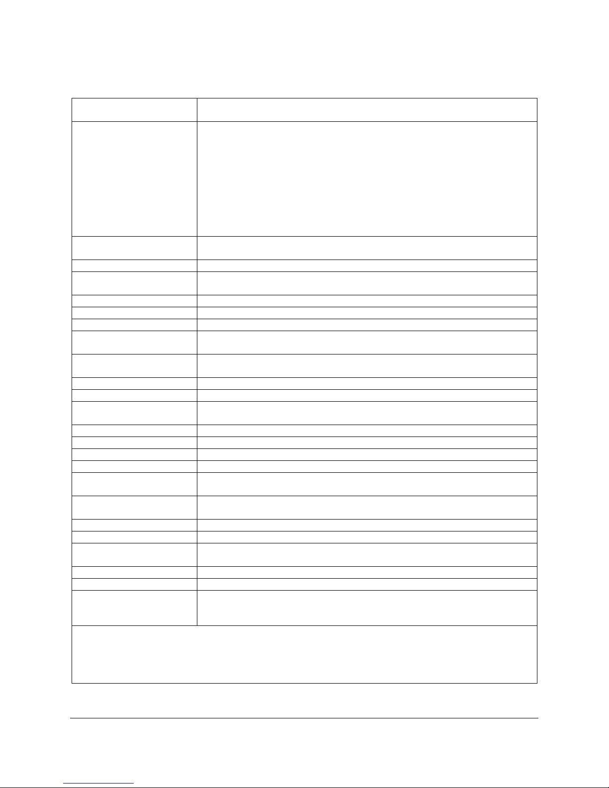
Technical Specifica tion
Analysis Method
Non-dispersive infrared, configured as an absolute absorptiometer with
microprocessor control of linearization
CO2 Measurement
0-1000 ppm (µmol mol-1)
Readings are automatically corrected for temperature and pressure.
Accuracy
< 1% of span concentration over the calibrated range but limited by the
accuracy of the calibration mixture.
Linearity
< 1% throughout the range
Stability
Auto-zero at regular intervals corrects for sample cell contamination,
source and detector ageing and changes in electronics.
Warm-up Time
Approximately 15 minutes
Sampling Rate
10 Hz. Sample data is averaged and output ever y 1.0 seconds.
Sampling Pump
Integral, long life 12V air sampling pump
Gas Flow Rate
200-500 cc/min (280-340 cc/min is optimal). An internal, electronic flow
sensor monitors flow rate.
Terminal Block
System power, analog, digital and current (4-20mA) outputs and sensor
inputs are available from the 22 pin terminal block
Analog Output
0-2.5V (CO2 range selectable) and 4-20mA
Digital Output
RS232 and USB
Air Filter & Water Trap
An external water trap and internal hydrophobic filter are used to protect
analyzer from water.
Alarm
Visual and audible alarm/war nings. 2 relay contacts (Alarm1 and Alarm2)
CO2 Control
High and low user set points
Data Storage (USB)
USB Flash Drive for data storage in multiple formats.
Display
2.7” electronic paper touch display with 264 x 176 pixel resolution
Power Requirements
12 VDC, 1.5A or
100-240 VAC, 50-60 Hz, 0.6A (AC Adapter included)
Power Consumption
Warm up: 12W (12V @ 1.0A)
Normal operation: 6W (12V @ 0.5A)
Enclosure
High impact, IP65 enclosure
Gas Connections
Two barbed fittings (inlet and exhaust) for use with 1/8” (.125”) ID tubing
Operating Temperature
0-50 oC, non-condensing. External filtration may be required in dirty
environments.
Dimensions
213 cm L x 185 cm H 114 cm W (Enclosure only)
Weight
1.5 kg
Optional Accessories
- H2O Sensor - Range: 0-Dewpoint (mb)
- WIFi
PP Systems is a registered trademark of PP Systems, Inc.
respective owners.
Ranges
0-2000 ppm (µmol mol-1)
0-5000 ppm (µmol mol
-1
0-10000 ppm (µmol mol
0-20000 ppm (µmol mol
0-30000 ppm (µmol mol
0-50000 ppm (µmol mol
0-100000 ppm (µmol mol
)
-1
)
-1
)
-1
)
-1
)
-1
)
- O2 Sensor – Range: 0-100%
PP Systems is continuously updating its products and reserves the right to amend product
specifications without notice. All brand names are trademarks or registered trademarks of their
Page 9
Summary of System Design
Overview and Theory
The WMA-5 is designed to function as a self-contained instrument for continuous measurement of CO2 in
air. Its open-path design allows for continuous, unattended air sampling, as the pump introduces fresh
sample gas to the essential component, the IRGA (infrared gas analyzer).
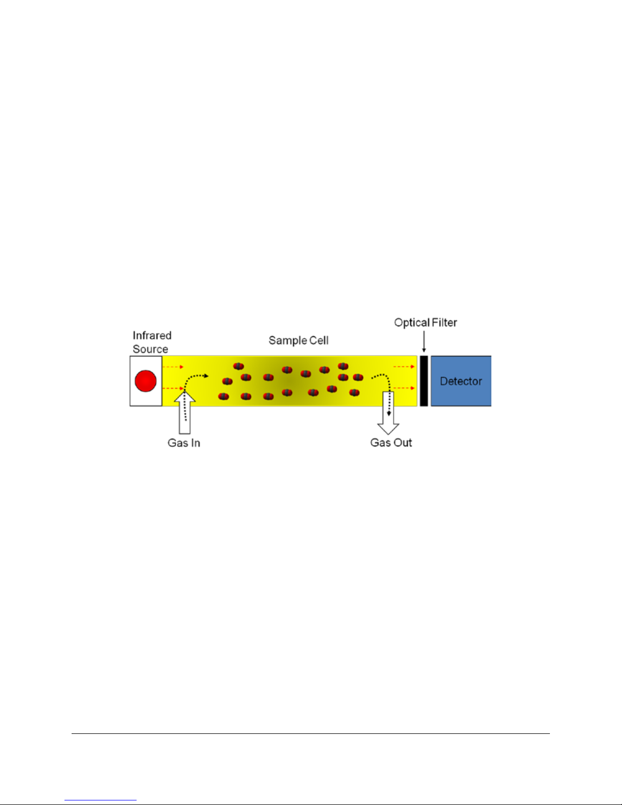
The IRGA forms the core of gas analysis systems that measure CO
refers to the transmission of a broad-band inf ra-red wavelength from the IRGA source lamps. A single
IRGA consists of four basic components:
. Non-dispersive infra-red (NDIR)
2
• Infra-red source
• Sample cell of known path length and volume
• Optical interference filter
• Infra-red detector
The theory itself is quite simple – light from mid-infra-red wavelengths is produced by the source and
pulsed through a gold plated cell. The interference filter narrows the bandwidth of the IR source received
by the detector to the signature wavelength absorbed by the target gas molecule, e.g. CO
employs a unique optical filter. As the sample gas fills the cell, the target gas molecule absorbs IR
energy at the particular wavelength, and the reduction in IR energy reaching the detector is measured.
The higher the target gas concentration, the lower the infra-red signal received at the detector, as defined
by the Lambert-Beer Law of Attenuation.
. The CO2 cell
2
CO
molecules have a discrete absorption band at 4.26 µm that has very little overlap with any other
2
molecule’s absorption band, so that wavelength provides good sensitivity and selectivity. The WMA-5
electronics could be considered another major component, which processes raw analog-to-digital (A/D)
information from the IRGA detector, accurately translating this information into gas concentrations.
Page 10

The WMA-5 detector is optimized
for this CO2 waveband (4.26 µm)
The gas sample is of course a mixture of gas molecules, and this can present problems in terms of
accurate detection of concentrations of a specific gas, such carbon dioxide. This effect, foreign gas
broadening (FGB), must be corrected to ensure accurate measurement of gas concentrations. With FGB,
the CO
This effect is about 0.1 µmol mol
in infra-red absorption, which is detected as an apparent increase in [CO
gas in the IRGA cell is somewhat diluted by the increased air volume induced by water vapor.
2
-1
CO2 mb-1 H2O. The presence of water vapor also causes an increase
]. This is of a similar magnitude,
2
but opposite to the dilution effect, and the WMA-5 automatically corrects these FGB effects.
The WMA-5 IRGAs are quite stable owing to their construction, calibration and thermal environment, but
various circumstances can cause apparent changes over time. Some changes may require recalibration,
although one of the strengths of the WMA-5 is that recalibration is not a routine (annual) maintenance
task as a result of our innovative “Auto-Zero” function. Our Auto-Zero function corrects for nearly all
changes that result in calibration drifts. It minimizes effects on span (gas sensitivity), of sample cell
contamination, lamp ageing, changes in detector sensitivity, amplifier gains and reference voltages.
Measurements are ratioed to the Zero reading before IR absorbance is determined. From the
relationship between absorbance and concentration determined in the factory for each instrument, and
the current calibration factor, the sample concentration is determined.
Page 11

Optional Sensors for use with WMA-5
O2 Sensor
An optional electrochemical O2 sensor can be used with the WMA-5 for measurement of oxygen in
addition to CO
.
2
• Range: 0-100%
• Response Time: ≤ 15 seconds at 23 ± 2
• Linearity: ± 1.0% of full scale
The O
to sample the incoming gas stream. Recalibration should not be necessary and based on our experience
with this sensor it should have a working life of approximately 4-5 years.
sensor is mounted into a manifold located inside the terminal block enclosure and is fitted in-line
2
o
C
H2O Sensor
An optional solid state H2O sensor can be used with the WMA-5 for measurement of H2O in addition to
CO
.
2
• Range: 0-Dewpoint (mb)
• Accuracy: < 2% RH
The humidity sensor is mounted into a manifold located inside the terminal block enclosure and is fitted
in-line to sample the incoming gas stream. Readings are displayed and recorded in absolute vapor
pressure (mb). Recalibration of this sensor is not necessary.
Mechanical Specifications & Mounting
Instructions
The WMA-5 is very easy to mount. The rear of the enclosure has convenient markings showing where to
place mounting screws. All dimensions are in centimeters (cm).
System Power
The WMA-5 is supplied with its own power supply to allow operation from local mains power. The
specification of the power supply is as follows:
Input: 12 VDC, 1.5A or 100-240 VAC, 50-60 Hz, 0.6A (AC adapter included)
The WMA-5 can be powered by 12V if required via direct connection to the terminal block. It requires a
12V DC input at 1.5A. Connect the positive to +12V and the negative to GND. The terminal block is
clearly marked for ease of connection.
Page 12
Getting Familiar with the WMA-5
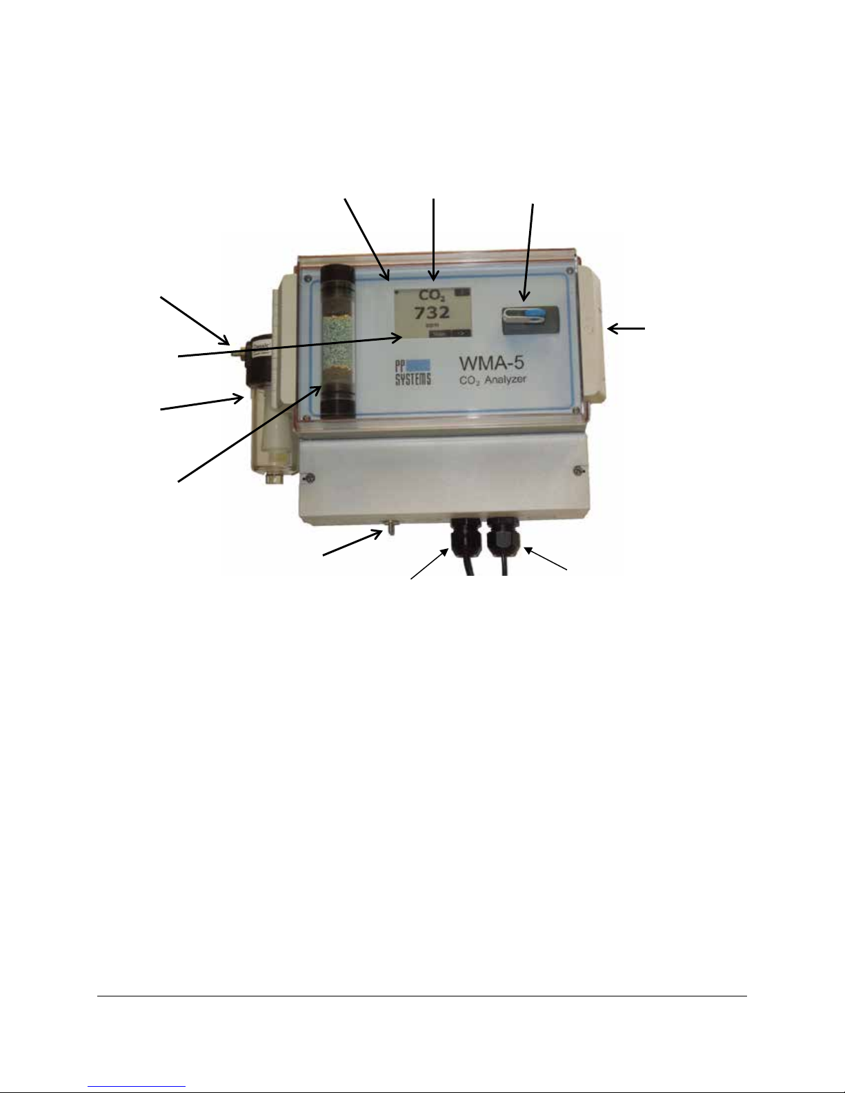
Gas Inlet
Latch to open
Terminal Block Enclosure
Power
Data Port
Gas Outlet
Status Box
Water Trap
Absorber
Column (CO
Scrubber)
Power Status (♥) Touch Display USB Flash Memory Port
clear cover to
access display,
absorber and
USB port.
2
Touch Display
The WMA-5 features a 2.7” a-Si, active matrix TFT, Electronic Paper Display (EPD) touch panel. The
panel has such high resolution (117 dpi) that it is able to easily display fine patterns. Due to its bi-stable
nature, the EPD panel requires very little po wer to update and nee ds no power to m aintain an im age.
Features
• a-Si TFT active matrix Electronic Paper Display(EPD)
• Resolution: 264 x 176 pixel
• Ultra low power consum ption
• Super Wide Viewing Angle - near 180°
• Extra thin & light
• SPI interfac e
• RoHS compliant
Status Box
All messages and warnings are displayed in the Status Box which is located in the bottom left hand
corner of the display. A flashing ♥ (Heart) symbol in the upper left hand corner of the display indicates that
the system is powered on.
Page 13

Gas Ports
There are two gas ports (barb fittings) on the WMA-5. The gas inlet is located on the water trap and the
gas outlet is located on the bottom of the WMA-5 enclosure. Each port is designed for use with 1/8”
(.125) ID tubing. The sampling line should be fitted to the gas inlet port using 1/8” tubing. The gas outlet
should be left open to atmosphere to allow the sample air to exhaust without restriction.
Water Trap
The water trap (also referred to as a “Float Valve Housing”) is an essential filtration tool when gas is being
drawn to the CO
How the Water Trap Works
As liquid is collected in the bowl the level starts to rise, gas becomes trapped in the open-end of the float
and it too starts to rise. The entire float assembly then begins to move upwards and eventually closes the
valve and shuts of the flow to the analyzer. This loss of flow is then detected by the WMA-5 mass flow
controller ensuring flow is cut-off to the analyzer. An error message is also displayed in the Status Box.
analyzer preventing the carry-over of water from getting into the system.
2
Terminal Block
A terminal block is located inside the small rectangular enclosure below the main enclosure for simple
and convenient connection to external devices (i.e. power, RS232, power, microprocessors, etc.). To
access the terminal block, remove the two screws on either side of the enclosure to remove the cover.
We recommend that the terminal block cover is always fitted and secured in place during operation.
Page 14
Recommended Cable Interface
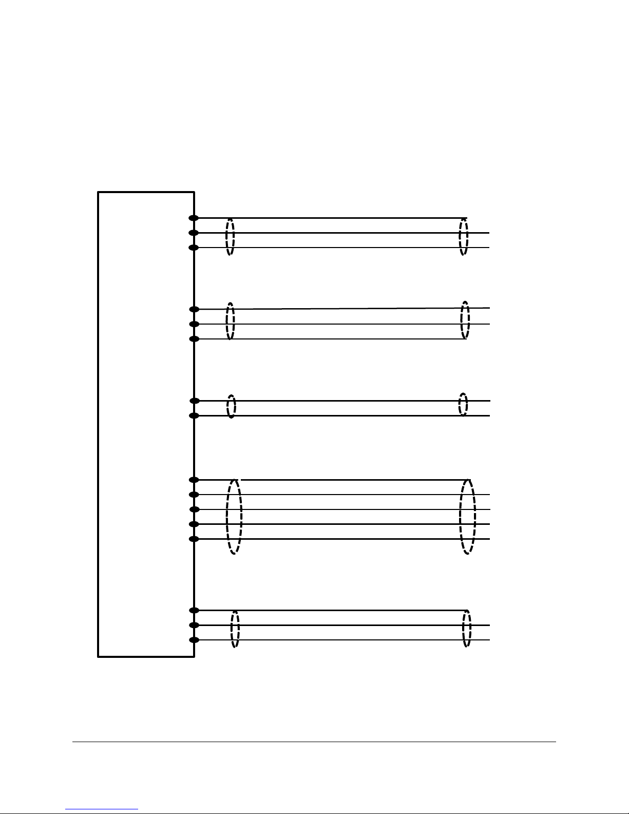
WMA-5 Terminal Block
Vout
GND
Shielded cable to external relays or Programmable Logic Controller
Typical cable Belden 9609 4C 24 Shielded. Length 10 Ft Maximum.
Shielded cable to Data Logger or Programmable Logic Controller
Typical cable Belden 8413 2C 24 Shielded. Length 5 Ft Maximum.
GND
Alarm 1
Alarm 1
Alarm 2
Alarm 2
GND
TX RS232
RX RS232
Supply 4-20
Iout 4-20
GND
GND
5V out
AUX1 in
Shielded cable to PC or Data Logger
Typical cable Belden 9609 4C 24 Shielded. Length 10 Ft Maximum
Shielded cable to Data Logger
Typical cable Belden 8413 2C 24 Shielded. Length 10 Ft Maximum.
Shielded cable to sensor of manual zero switch
Typical cable Belden 9609 4C 24 Shielded. Length 5 Ft Maximum.
When connecting up to external devices via the WMA-5 terminal block we recommend the following cable
type and lengths.
Page 15

USB Memory Stick Port
A USB Memory Stick Port is available on the front panel to allow users to save data directly to a USB
flash drive (also commonly referred to as a “thumb drive” or “memory stick”). When a USB flash drive is
inserted into the USB Memory Stick port, the LED indicator will first turn red in recognition of the flash
drive and then it will flash green indicating that it is available to save data to it.
Flow Adjustment
The WMA-5 features an internal electronic flow sensor for measuring the flow. It is factory calibrated by
the manufacturer and should remain within the accuracy tolerance for life. Flow rate is adjustable by
changing the Pump Power percent in the Flow settings in the touch display.
Flow Range: 200-500 cc/min
We recommend a flow rate of 280-340 cc/min for optimal performance.
Important Note
If the WMA-5 is reading low CO2, chances are that there is no flow through the analyzer. Check the water
trap to make sure that it is not filled with water.
Absorber Column and CO2 Scrubber
The absorber column contains a CO2 scrubbing desiccant commonly referred to as Soda Lime. When air
passes through this column, it removes all of the CO
into the WMA-5 periodically switches the flow of gas from the analyzer through this column to check the
analyzer zero. This routine ensures long term stability and accuracy of the CO
corrects for such things as sample cell contamination, source aging, detector sensitivity and changes in
electronics.
from the air stream. The “Auto-Zero” facility built
2
analyzer. It automatically
2
Soda Lime (CO
Soda lime (Sodium Hydroxide) is used to remove CO
(white to violet) and non-indic at ing So da Lime can be can be used with the WMA-5. Refer to Soda Lime
on page 68 for maintenance and replacement information.
Scrubber)
2
from air entering the WMA-5. Both self-indicting
2
Data Port
The Data Port line can be connected to the COM port of a PC that is running a terminal emulation
program (i.e. Hyperterminal). Measure data is continuously sent through this port.
Page 16

Routine System Checks
The WMA-5 is designed to monitor CO2 24/7 and should require minimal maintenance. The routine
system checks are as follows:
Flashing Heart (♥) – Make sure that the heart symbol is flashing in the upper left hand corner.
Water Trap – Periodically inspect for water build-up and empty as required.
Status Box – Inspect periodically for error messages/warnings.
Absorber Column
• Make sure absorber column is seated properly in its manifold.
• Soda lime is fresh to ensure that the unit receives a good Zero to maintain calibration and
stability. If you have any doubt about the freshness of the soda lime you should replace it.
• All “O” rings are lubricated with silicone grease to ensure good seal and to avoid problems
associated with breaking or cracking.
• Inspect gray foam filters and replace if worn or reduced in size.
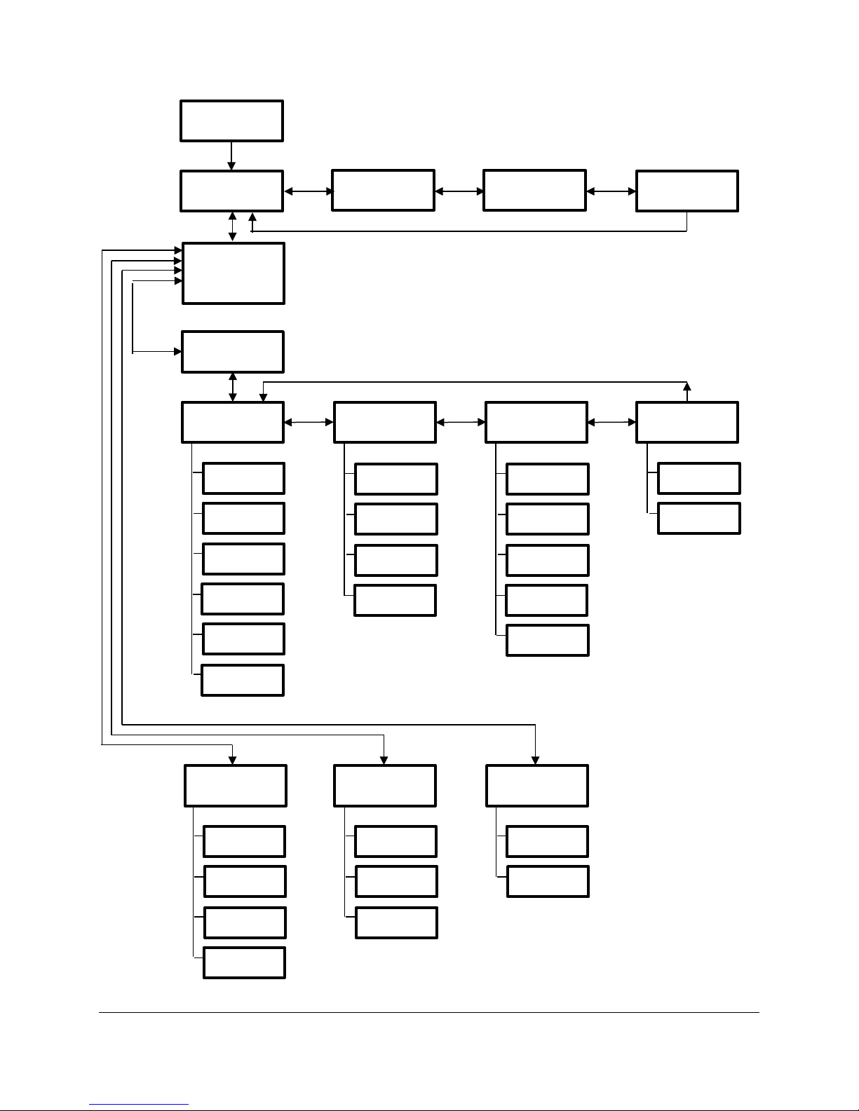
Touch Display Overview
The flowchart below describes an overview of the touch display for the WMA-5. When the instrument is
first powered up, there is a brief period where the Splash screen is shown. After this time, the instrument
goes into the warm-up period which is appr oximately 10-15 minutes and the Measure screen is displayed.
During and after the warm-up period, the user has the ability to navigate through the menus as shown in
the flowchart below. The following sections describe each screen and its functionality.
Page 17
Main Menu
Settings 1
Menu
Settings 2
Menu
Settings 3
Menu
Settings 4
Menu
Settings
Menu
Zero
Alarms
Reset Abs
Flow
Alarm Sound
CO2 Unit
Analog
Averaging
WMA ID
Graph
Host
WiFi
Memory
Host Port
Reset WiFi
Set Clock
Defaults
Info
Menu
Diagnostics
Menu
Calibration
Menu
ADC
Zeros
Hours
Voltages
About
Contact
CO2
O2
Touch Cal
Splash Screen
CO2
Screen
Variables 1
Screen
Variables 2
Screen
Graphic
Display Screen
Page 18
Splash Screen
6
1
3 4 5
2
When the instrument is first powered up, the Splash screen is displayed momentarily, and then the
Measure screen is displayed.
General Screen Info
New screens are displayed by the user selecting either the lower left or the lower right buttons. Generally
speaking, the left button brings you back to the previous screen and the right button to the next available
screen.
Data Entry Screen
The Data Entry Screen is used to enter new num eric al values. The sc reen is displ a yed whene ver a ne w
value is required.
1. The name of the parameter.
Page 19
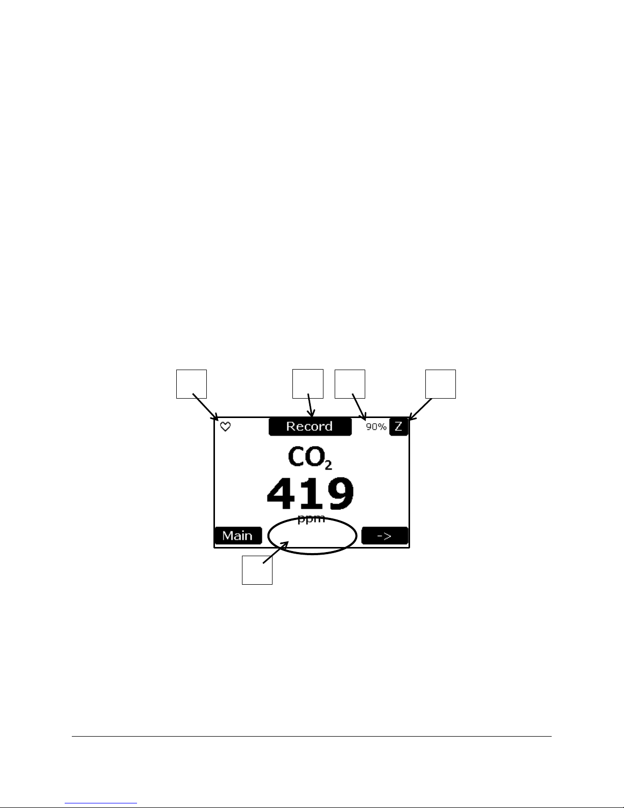
2. The units associated with the parameter.
1 3 4
5
2
3. The acceptable range of values.
4. The value being entered.
5. The OK button selects the entered value. If the entered value is out of range, it is set to the
minimum or maximum value. It then returns to the previous screen.
6. The Cancel button returns to previous screen without changing the initial value.
Measurement Mode
The Measurement Mode is comprised of four screens; Measure screen, Variables 1 screen, Variables 2
screen, and the Graphic Display screen. Each screen allows the user to view the WMA-5 data in various
ways. The screens can be rotated through by the user using the left and right arrow buttons. The initial
screen is the Measure screen which displays the value of CO
Second screen is the Variables 1 screen which displays the values of six variables in real time; CO
O
, Temperature, Flow Rate, and Pressure. The Third screen is the Variables 2 screen which displays
2
the values of four variables in real time; CO
screen which displays CO
, H2O or O2 concentration graphic all y over tim e.
2
, H2O, O2, and Aux. The forth screen is the Graphic Display
2
Measure Screen Info
concentration in a large bold font. The
2
, H2O,
2
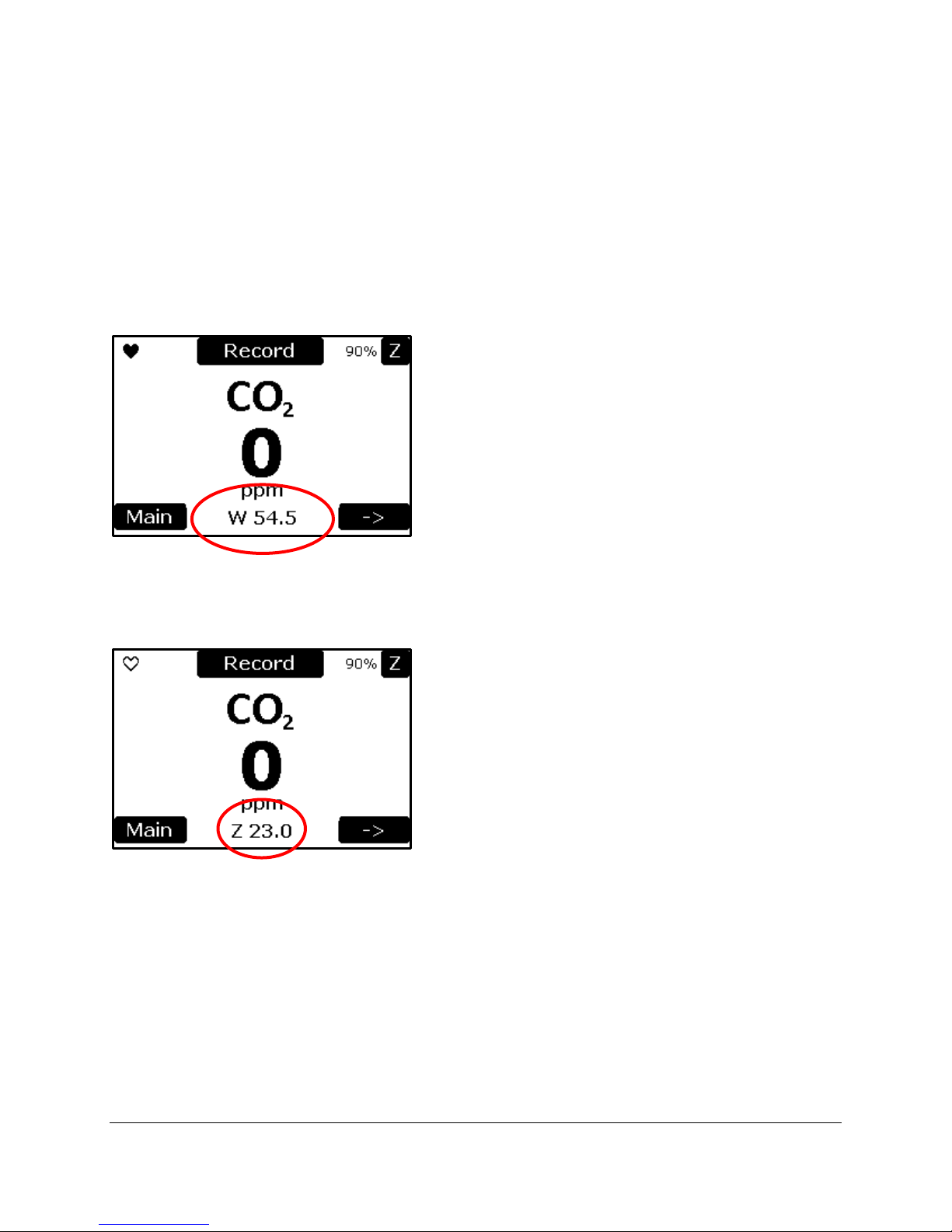
Each measurement screen contains these common features.
1. There is a pulsing
2. The Record button saves data as a marked record in the USB memory stick, and also sends the
record to the host and WiFi ports.
3. The percentage value in the top right corner is the estimated percentage of Auto-zero abs or ber
column capacity remaining based on the number of zeros performed since the last time the
counter was reset by the user (See Reset Zero Absorber on page xx).
♥ icon to confirm that the WMA-5 display is actively on.
4. The ‘Z’ button is used to initiate a manual zero.
5. A status or error message can be displayed in the Status Area.
Page 20
Measure Screen
The Measure screen is displayed after the Splash screen and when the WMA-5 is powered up. For the
first 10-15 minutes, the WMA-5 goes into a warm-up period until it achieves its stable temperature of
55°C and an Auto-Zero is performed. During this time, messages are displayed in the Status Box area
that indicates that the instrument is in the warm-up stage. At the completion of the warm-up period, the
proper CO
The Main and right arrow buttons are operational during and after the warm-up period.
Warming Up
value is displayed and the Status Box is blank.
2
The status of ‘W 54.1’ means the WMA-5 is warming and the CO
warm-up, the CO
value is displayed as 0.
2
IRGA temperature is 54.1°C. During
2
Performing a Zero
The status of ‘Z 23’ means the WMA-5 is performing a zero. The number is how many seconds it will take
to complete the sequence. A normal zero starts at 25 seconds. During a Zero, the CO
value is displayed
2
as 0 as the readings are not valid during the Zero sequence.
At the completion of the warm-up and the first Zero, valid readings are displayed.
Page 21
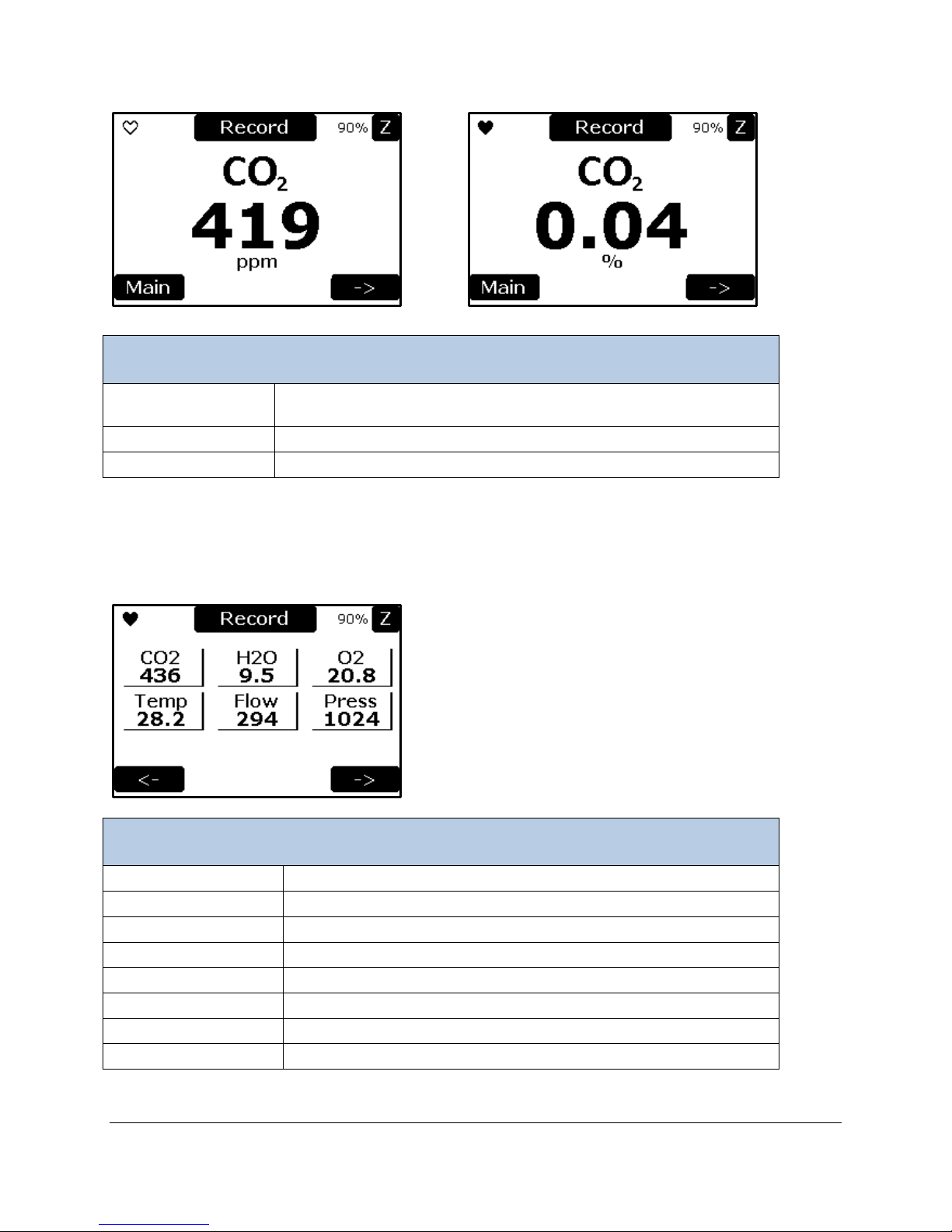
or
Measure Screen
CO2
CO2 Concentration (ppm or %). You can display CO2 in ppm or as a
percentage. See CO2 Units Settings on page 28.
Main Button
The Main Menu screen is displayed when this button is selected.
Right Arrow Button
Selects the next measurement screen (Variables 1 Screen).
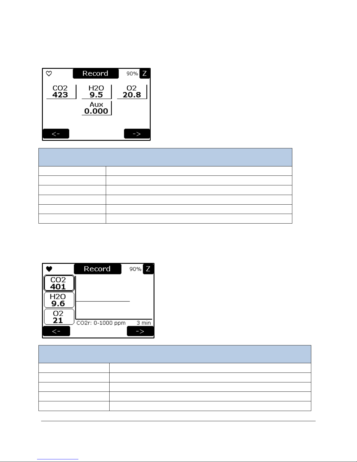
Variables 1 Screen
CO2
CO2 concentration reading (ppm).
H2O
H2O reading (mb), only if optional humidity sensor is installed.
O2
O2 reading (%), only if optional O2 sensor is installed.
Temp
Inlet air temperature (C), only if optional humidity sensor is installed.
Flow
Flow rate reading (cc/min).
Press
Absolute pressure in sample cell (mb).
Left Arrow Button
Displays the previous measurement screen, the Measure Screen.
Right Arrow Button
Displays the next measurement screen, the Variables 2 Screen.
Variables 1 Screen
The Variable 1 screen displays the values of six variables in real time; CO2, H2O, O2, Temperature, Flow
Rate, and Pressure.
Page 22
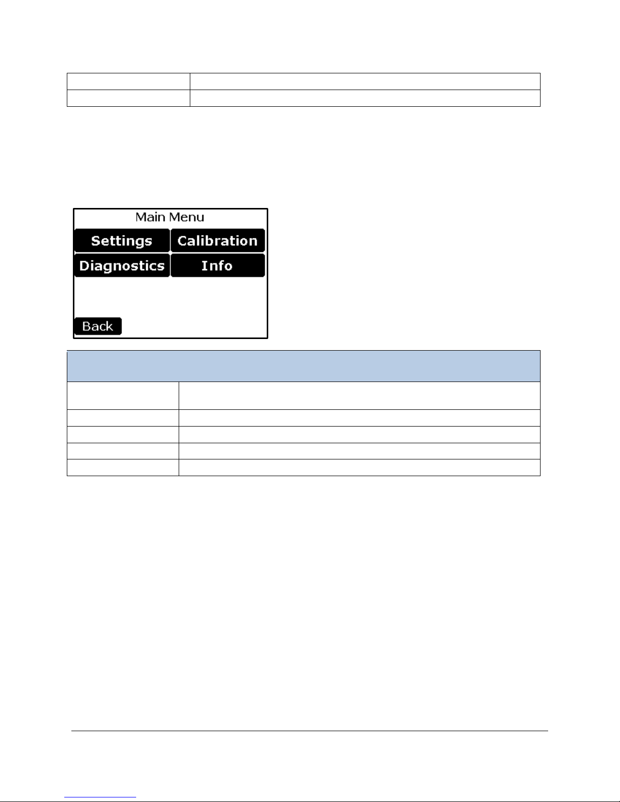
Variables 2 Screen
Variables 2 Screen
CO2
CO2 concentration reading (ppm).
H2O
H2O reading (mb), only if optional humidity sensor is installed.
O2
O2 reading (%), only if optional O2 sensor is installed.
AUX
AUX1 input voltage (volts)
Left Arrow Button
Displays the previous measurement screen, the Variables 1 Screen.
Right Arrow Button
Displays the next measurement screen, the Graph Screen.
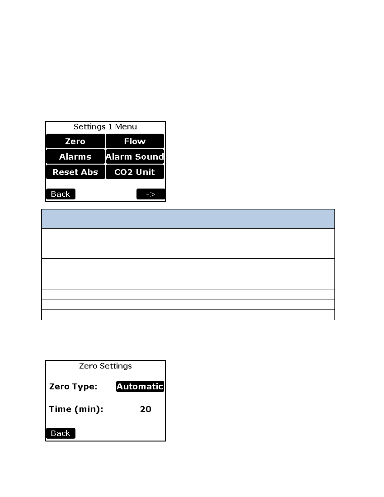
Graph Screen
CO2 Button
Selectable parameter to graph (0 – 100000 ppm)
H2O Button
Selectable parameter to graph (0 - 30 mb)
O2 Button
Selectable parameter to graph (0 – 100 %)
Y-axis
Range and units are located under the graph on left side
X-axis
X-axis time; fixed value of 3 minutes.
The Variable 2 screen displays the values of four variables in real time; CO2, H2O, O2, and Aux.
Graph Screen
The Graph screen shows a real-time display of the data.
Page 23
Left Arrow Button
Goes back the previous screen (Variables 2 Screen).
Right Arrow Button
Selects the next measurement screen (Meas ure Sc r ee n).
Main Menu
Settings Button
Controls major settings of the WMA-5. There are four sub menus under
Settings.
Diagnostics Button
Performs system diagnostics for troubleshooting purposes.
Calibration Button
Used to calibrate the CO2 gas analyzer, O2 Sensor, and the Touch Screen.
Info Button
To obtain version information and contact info
Back Button
Goes back to Measure screen
Main Menu
The Main Menu screen is displayed when the Main button is selected in the Measure screen. This menu
is the top level menu for all settings and user functionality of the system.
Page 24
Settings
Settings 1 Menu
Zero Button
Change/view the settings associated with the zero (zero type and time interval
for performing zeros).
Alarms Button
To set the CO2 limits low and high which will cause an alarm
Reset Abs Button
To indicate that absorber material has been replaced and reset.
Flow Button
To set sample flow
Alarm Sound Button
To enable or disable the alarm sounds
CO2 Unit Button
To Select the units for Measure Screen Display (ppm or %)
Back Button
Returns to the Main Menu.
Right Arrow
Continues to the Settings 2 Menu screen.
There are four settings menus; Settings 1-4. Generally, the settings have been grouped related to their
frequency of change and common functionality.
Settings 1 Menu
This menu contains the first tier and most common settings for the WMA-5 including the Zero, Alarms,
Reset Abs (Reset Absorber Column), Flow, Alarm Sound, and CO
Units.
2
Zero Settings
This function allows the user to change/view the zero parameters used by the WMA-5.
Page 25
Zero Settings
Zero Type Button
There are three types of zeros that can be performed; Automatic, Manual and
User Set. WE RECOMMEND AUTOMATIC.
Time Button
Zero time is the interval between zeros in minutes.
Time is always 20 minutes for Automatic. When Zero Type is set to User Set,
the time can be selected and set.
Back Button
Returns to the Settings 1 Menu.
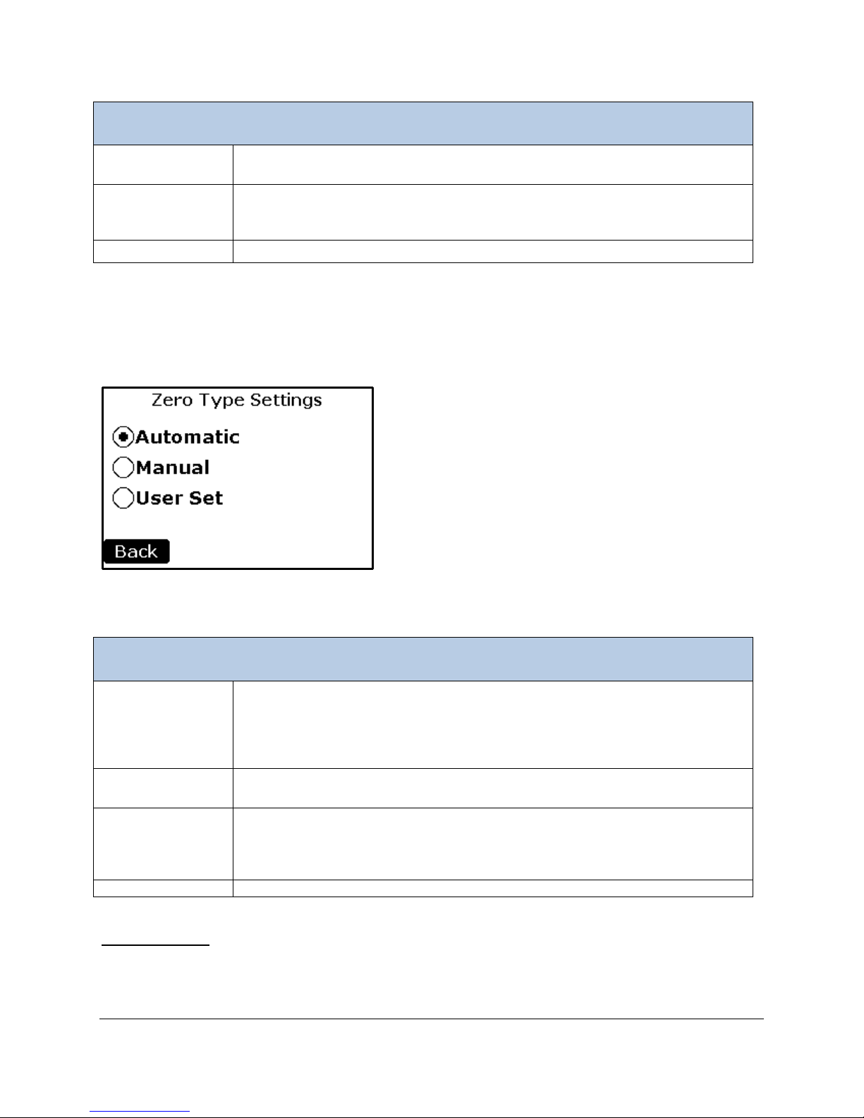
Zero Type Settings
Automatic Button
This is the default and recommended Zero Type. The WMA-5 performs a zero
minutes thereafter. The Zero Time interval is fixed at 20 minutes.
Manual Button
A zero can be initiated at any time and regardless of the Zero Type Setting by
pressing the Z button in the upper right hand corner of the display.
User Set Button
When selected, the WMA-5 performs a zero on start up, then again after 3
set from 1 to 40 minutes.
Back Button
Returns to the Zero Settings screen.
Zero Type Settings
Press the desired setting either directly on the radio button or on the text to the right of the radio button.
Then select the Back button to return to the Zero Settings screen. The Zero Settings screen will return
with the updated Zero Type value in the button box.
more frequently initially after achieving the IRGA warm-up temperature (55 oC).
At completion of warm-up it will perform an initial zero, then again after 3
minutes, then again after 6 more minutes, then after 12 minutes, then every 20
Important Notes
A Zero can be performed at any time either automatically or using the “Z" button in the Measure Screens.
In this case, the timer resets back to zero and will perform another zero when the Zero Time interval has
minutes, then again after 6 more minutes, then after 12 minutes, then finally
after 20 minutes. It then performs zeros at the user-specified interval. It can be
Page 26
Alarm Settings
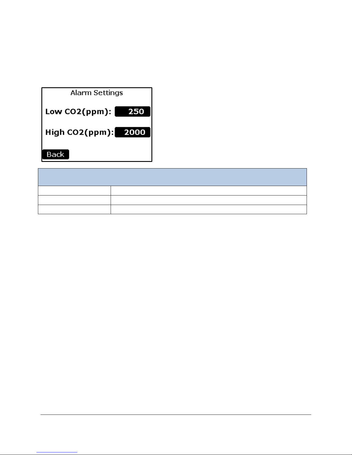
Alarm Settings
Low CO2 (ppm) Button
To set the low CO2 limit value at which an error is generated.
High CO2 (ppm) Button
To set the high CO2 limit value at which an error is generated.
Back Button
Returns to the Settings 1 Menu.
This function allows the user to change/view the low (ALARM1) and high (ALARM2) alarm facilities that
are built into the WMA-5. An alarm consists of an audio beep (if enabled in the Alarm Sound Setting
screen), an information message in the Status Box in the Measurement Mode screens and a relay switch
closure. There is a relay switch for each alarm: low (ALARM1) and high (ALARM2).
Low CO2 Alarm Setpoint
To change the Low CO2 Setpoint, select the button to the right of the “Low CO2 Setpoint (ppm):” text. The
numerical keypad will appear allowing a new number to be inputted. See numerical keypad description
under Zero Time section for details.
The WMA-5 is supplied with a factory default low alarm setting of 250 ppm. The reason for this is that a
typical low CO
value is the result of one of the following scenarios:
2
• Low or no air flow.
• Absorber column exhausted (soda lime).
• Zero valve failure.
The low alarm (ALARM1) terminal relay switch handles the output when CO
is below the low settings.
2
High CO2 Alarm Setpoint
To change the High CO2 Setpoint, select the button to the right of the “High CO2 Setpoint (ppm):” text.
The numerical keypad will appear allo win g a new num ber to be inputte d. See nu merical keypad
description under Zero Time section for details.
The default WMA-5 high alarm setpoint setting is 2000 ppm.
The high alarm (ALARM2) terminal relay switch handles the output when CO
Once the desired values are displayed, the Back button is selected to return to the Settings Menu.
exceeds the high settings.
2
Page 27
Reset Zero Absorber
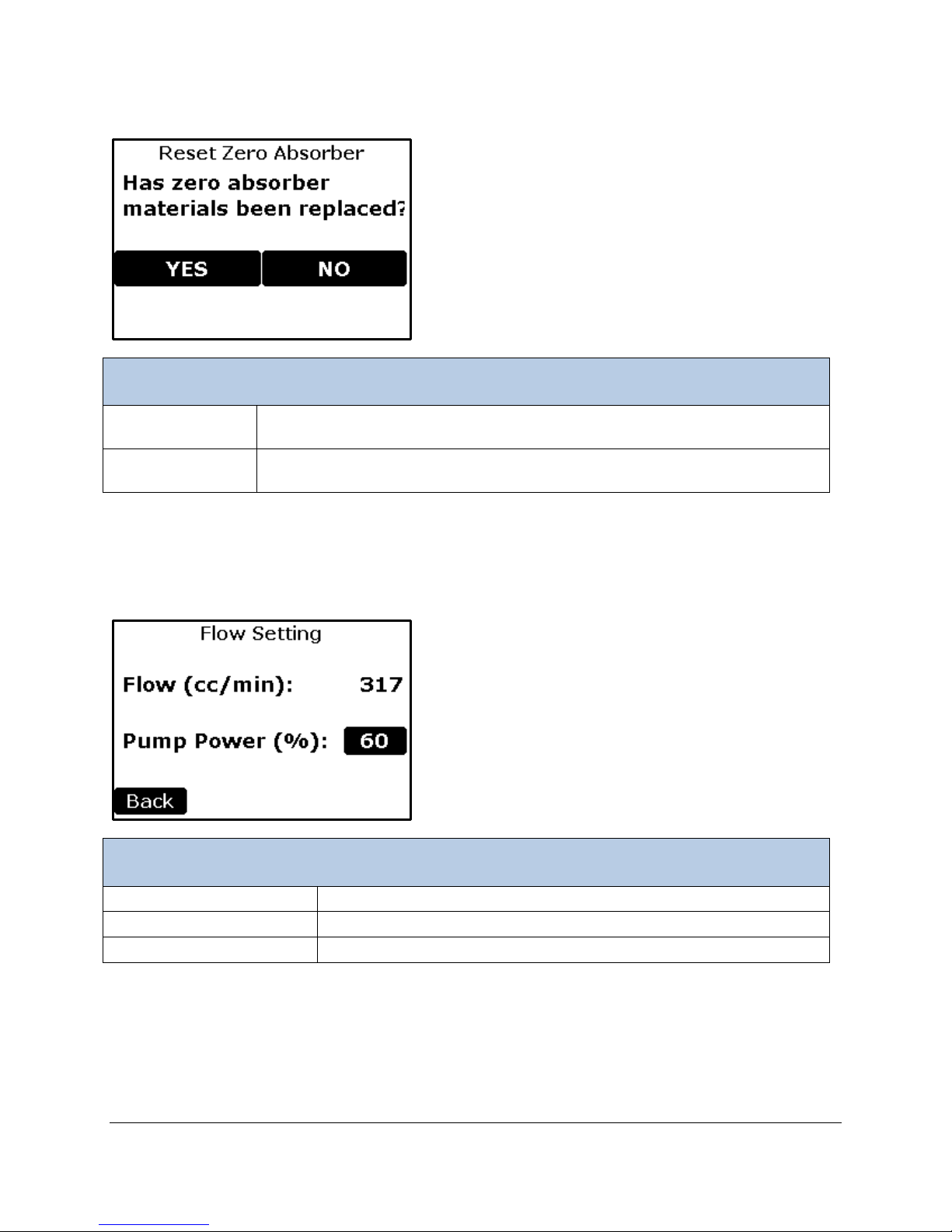
Reset Zero Absorber
Yes Button
Reset the Zero Absorber capacity gauge to 100%. This should be set every time
the soda lime is changed in the Auto-Zero column to ensure reporting accuracy.
No Button
Returns to the Settings 1 Menu without resetting the Zero Absorber capacity
gauge.
Flow Settings
Flow (cc/min)
The measured flow rate
Pump Power (%) Button
The Pump Power setting (0-100%)
Back Button
Returns to the Settings 1 Menu.
Flow Settings
This function allows the user to change/view the Flow rate of the WMA-5.
Page 28

Alarm Sound Settings
Zero Settings
Alarm Sound Button
To Select Yes or No ( enable or disable the Alarm Sound)
Back Button
Returns to the Settings 1 Menu.
CO2 Units Settings
PPM Button
Sets the units for CO2 in the Measure Screen Display to ppm.
% Button
Sets the units for CO2 in the Measure Screen Display to %.
Back Button
Returns to the Settings 1 Menu.
CO2 Units Settings
Page 29
Settings 2 Menu
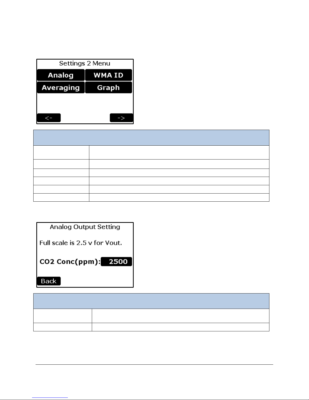
Analog Button
To set the CO2 concentration corresponding to the full scale analog output
value.
Averaging Button
Sets the CO2 averaging value range
WMA ID Button
To select an ID number of the WMA-5
Graph Button
To set the CO2 Y-axis range for the graph.
Back Button
Returns to the Settings 1 Menu screen.
Right Arrow Button
Continues to the Settings 3 Menu screen.
Analog Settings
CO2 Conc (ppm)
Button
To set the CO2 concentration corresponding to the full scale analog output
value.
Back Button
Returns to the Settings 2 Menu.
Settings 2 Menu
Analog Settings
Page 30
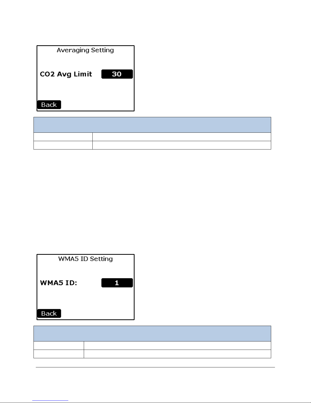
Averaging Settings
Averaging Settings
CO2 Avg Limit Button
To select the CO2 limit in which the CO2 is being averaged.
Back Button
Returns to the Settings 2 Menu.
WMA ID Settings
WMA ID Button
To Select device ID Range 0-9 (the Default is 1)
Back Button
Returns to the Settings 2 Menu.
Running Average: An exponential running average filter can be applied to smooth out small fluctuations
while remaining sensitive to larger differences by using an Average Limit value. Whenever a new reading
differs from the current running average by more than the CO
begins. Thus, when the CO
2 concentration is changing rapidly, averaging is suspended and the
instrument can track changes at the basic instrument data rate of 1 second. When the CO
set to 0, no running average is performed. The running average filter response time is 3.5 seconds to
reach 66% of a new value, and 16 seconds to reach 99%. In other words, if Avg Limit is set above 100
ppm and the inlet sample gas concentration instantaneously changed by 100 ppm, it would take 4
seconds for the CO
2 reading to change by 66 ppm; then after 16 seconds, the measured value would
change by 99 ppm.
2 Avg Limit value, a new running average
2 Avg Limit is
WMA ID Settings
Page 31
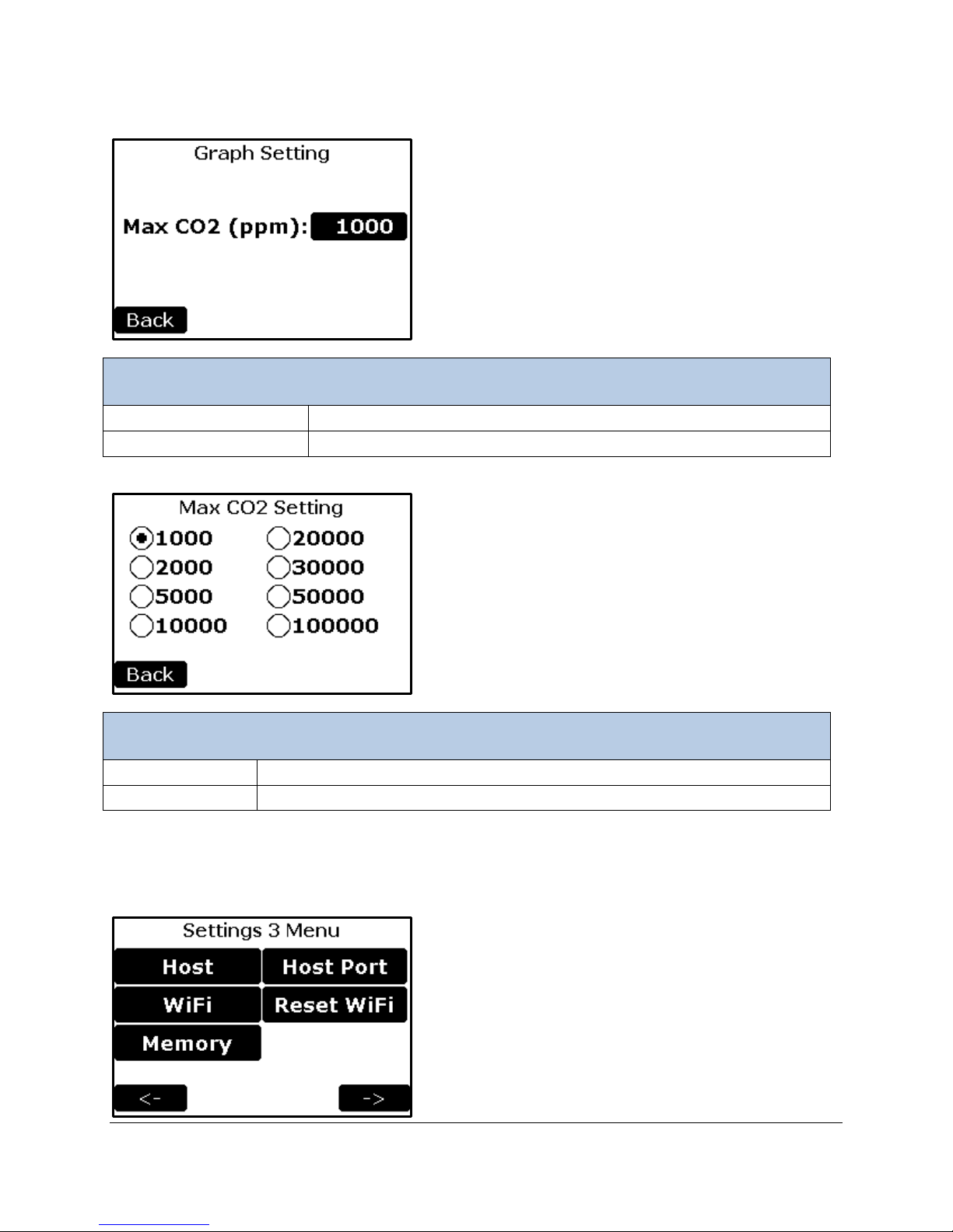
Graph Setting
Graph Settings
Max CO2 (ppm) Buttons
To select the CO2 Y-axis range for the Graph Screen
Back Button
Returns to the Settings 2 Menu.
Max CO2 Settings
Radio Buttons
Selects the CO2 Y-axis range for the Graph Screen
Back Button
Returns to the Graph Settings screen.
Settings 3 Menu
Page 32
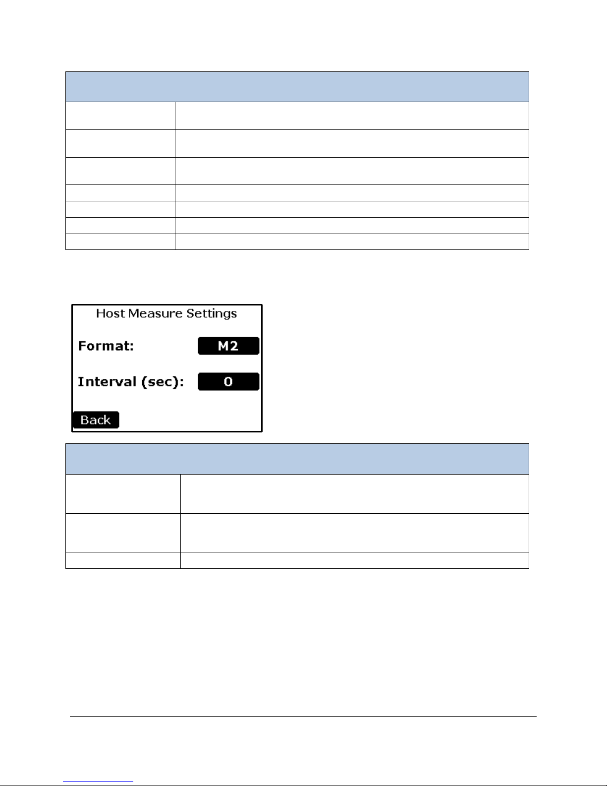
Settings 3 Menu
Host Button
Configures the data format and time interval that the measure data will sent to
a computer via a terminal emulation program (i.e. Hyperterminal).
WiFi Button
Configures the data format and time interval that the measure data will sent to
the internet.
Memory Button
Configures the data format and time interval that the measure data will sent to
a USB memory stick
Host Port Button
To select which Port to connect Host.
Reset WiFi Button
To reset Wi-Fi to Factory Settings (if installed)
Back Button
Returns to the Settings 2 Menu screen.
Right Arrow Button
Continues to the Settings 4 Menu screen.
Host Measure Setting s
Format Button
Determines the measure data format. All data formats are available (M1description of each format is below.
Interval (sec) Button
Determines the time interval in seconds in which the measure data will be
(1 hour). Default is 0.
Back Button
Returns to the Setti ngs3 M enu.
Host Settings
M6). The default is M2. See the Measure Format Settings table for a detailed
sent. A value of 0 stops sending data. The maximum value is 3600 seconds
Page 33
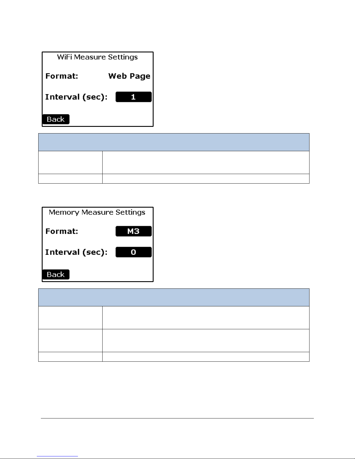
WiFi Settings
WiFi Measure Settings
Interval (sec) Button
Determines the time interval in seconds in which the measure data will be
(1 hour). Default is 1 second.
Back Button
Returns to the Settings3 Menu.
Memory Measure Settings
Format Button
Determines the measure data format. All data formats are available (M1-M6).
description of each format is below.
Interval (sec) Button
Determines the time interval in seconds in which the measure data will be
(1 hour). Default is 0.
Back Button
Returns to the Setti ngs3 M enu.
Memory Settings
sent. A value of 0 means no data sent. The maximum value is 3600 seconds
The default is M3. See the Measure Format Settings table for a detailed
sent. A value of 0 means no data sent. The maximum value is 3600 seconds
Page 34
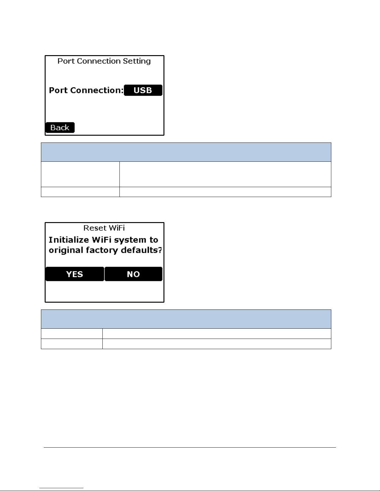
Host Port Settings
Host Port Settings
Port Connection Button
To select which Port to connect Host.
• Wi-Fi
Back Button
Returns to the Settings 3 Menu.
Reset WiFi Settings
Yes Button
Reset Wi-Fi to original Factory Settings then returns to Settings 3 Menu
No Button
Returns to the Settings 3 Menu without resetting Wi-Fi
Reset WiFi Settings
• USB
Page 35
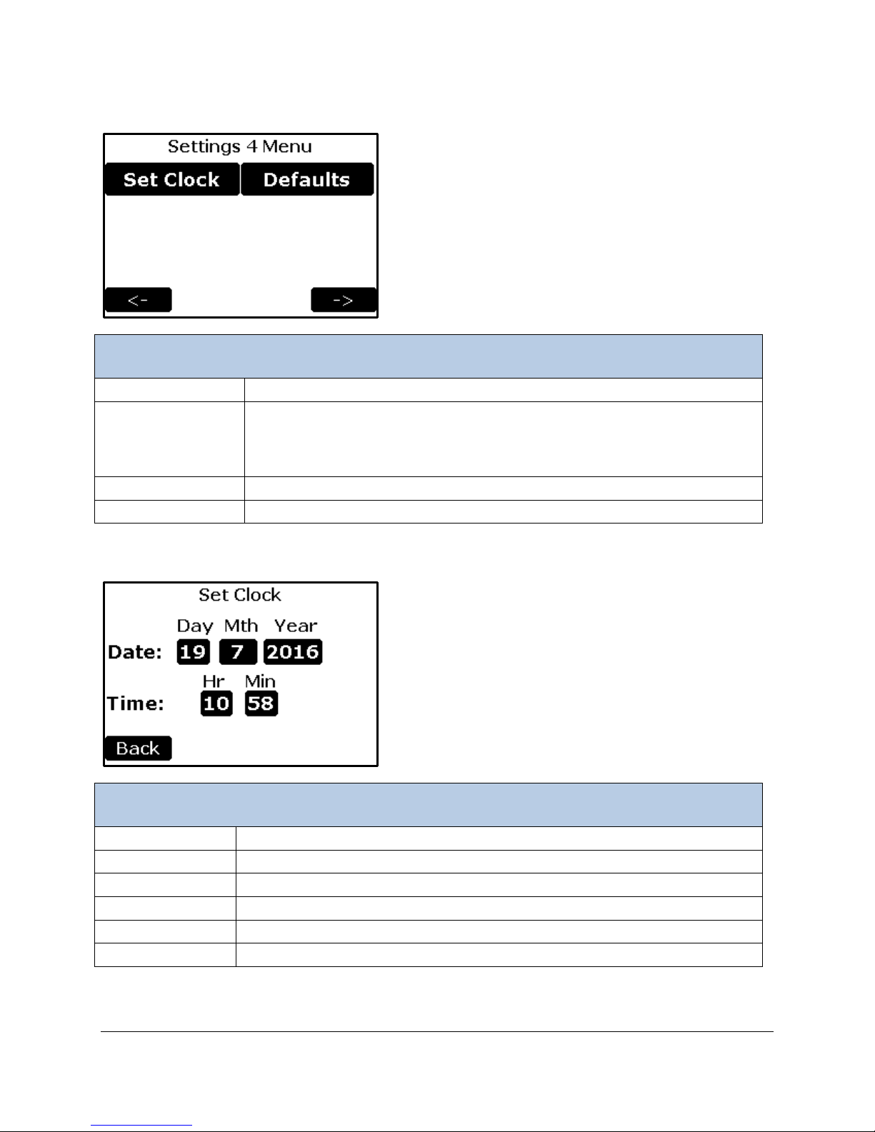
Settings 4 Menu
Settings 4 Menu
Set Clock Button
To set the time and date of the WMA-5
Defaults Button
To reset all parameters to factory defaults
Back Button
Returns to the Settings 3 Menu screen.
Right Arrow Button
Continues to the Settings 1 Menu screen.
Set Clock Settings
Day Button
To set the day (1 – 31)
Mth Button
To set the month (1 -12)
Year Button
To set the year (20XX)
Hr Button
To set the hour ( 0 – 23) (24 hour format)
Min Button
To set the minutes (0 – 59)
Back Button
Returns to the Settings 4 Menu.
This function allows the user to initialize the WMA-5 to its factory default
values. This feature may be needed to correct an erroneous calibration, or to
simply undo undesirable configuration changes.
Set Clock Settings
Page 36
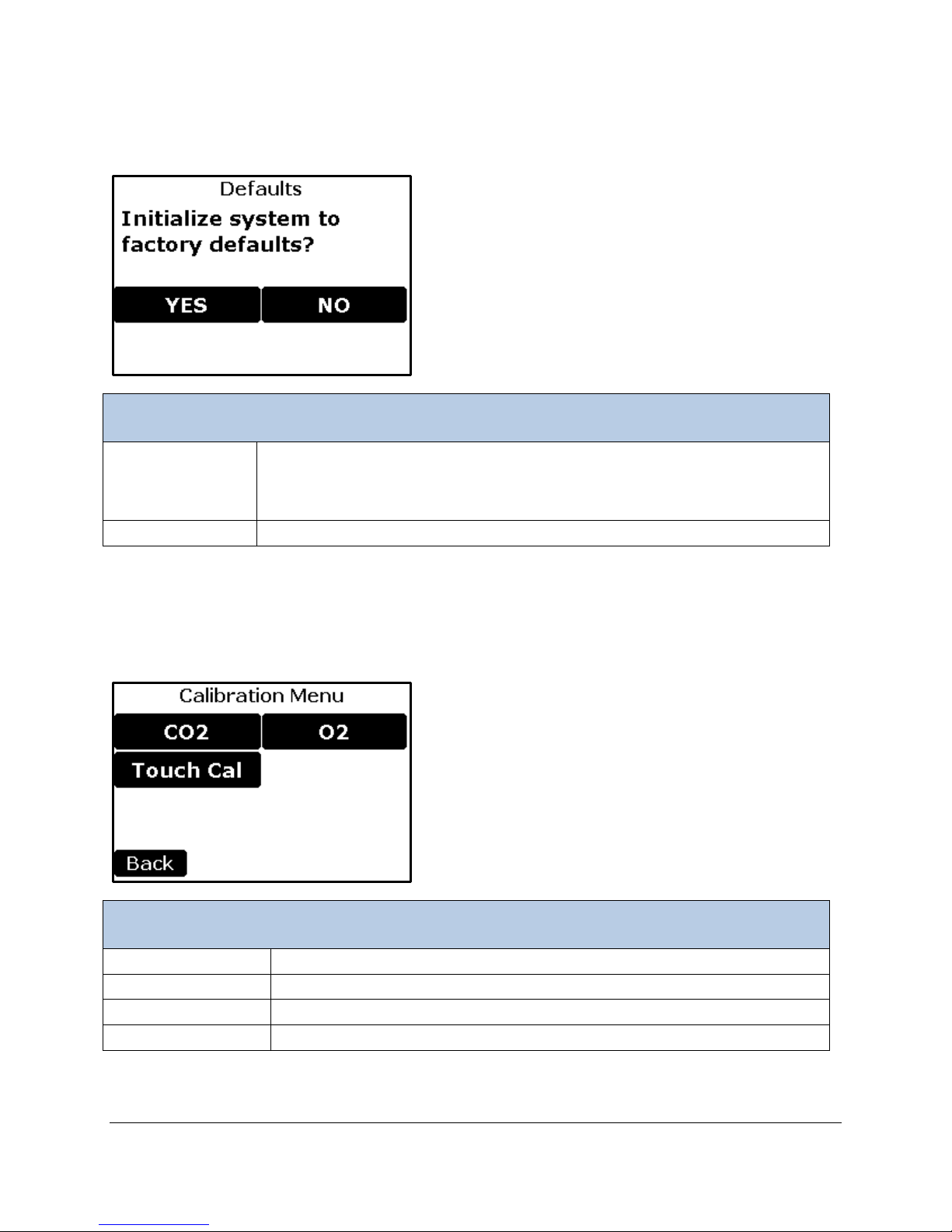
Default Settings
Yes Button
Resets WMA-5 to original factory settings then returns to Settings 4 Menu.
undo undesirable configuration changes.
No Button
Returns to the Settings 4 Menu with no changes.
Calibration Menu
CO2 Button
To perform CO2 calibration.
O2 Button
To perform O2 calibration.
Touch Cal Button
To perform Touch Screen calibration
Back Button
Returns to the Main Menu.
Default Settings
This function allows the user to initialize the WMA-5 to its factory default values.
This feature may be needed to correct an erroneous calibration, or to simply
Calibration
This WMA-5 allows calibration of the CO2 IRGA, the O2O Sensor, and the Touch Screen.
Page 37
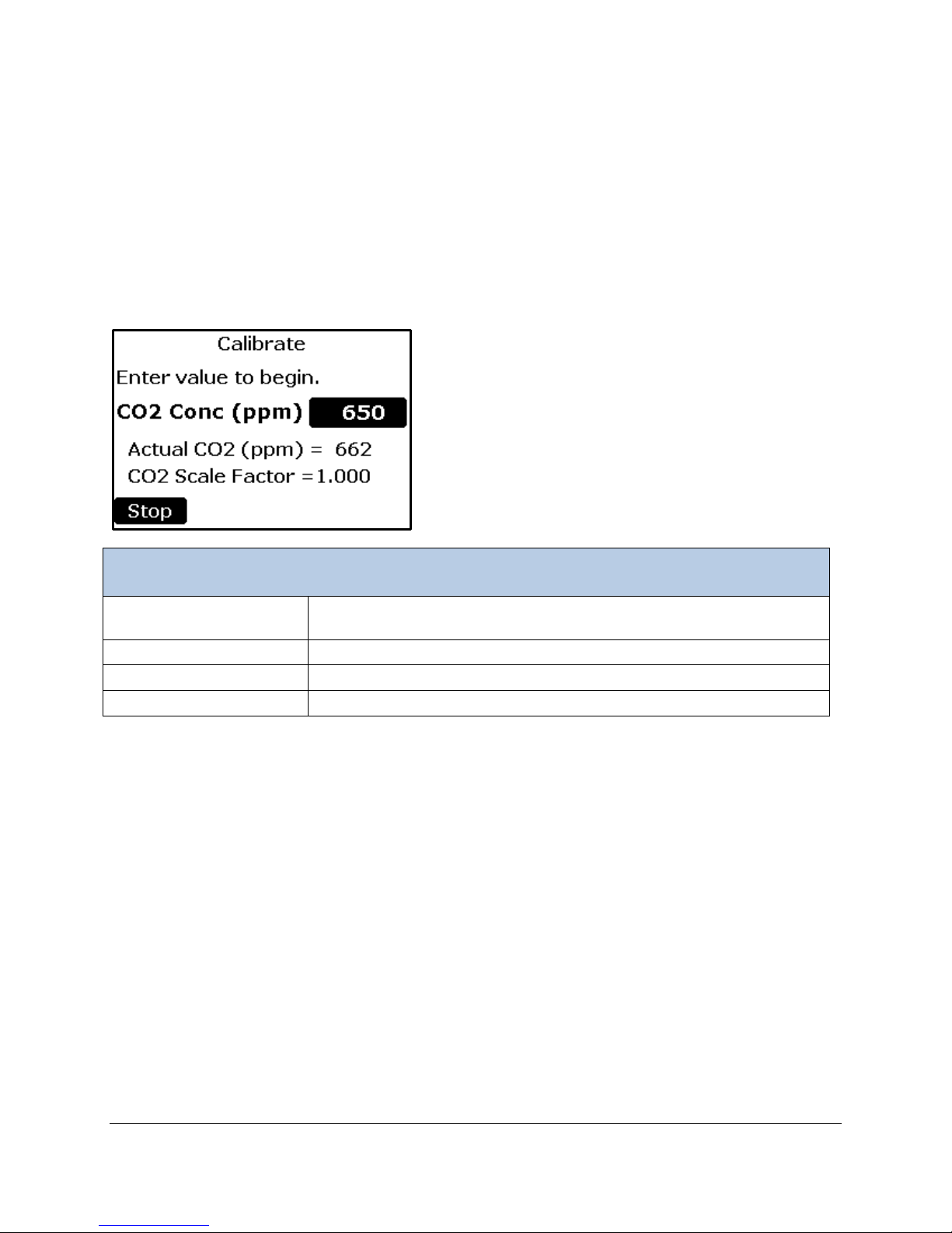
CO2 Calibration
Calibration
CO2 Conc (ppm) Button
CO2 concentration (ppm) of the calibration reference gas.
Entering a value will begin the calibra tion proc ess
Actual CO2
The current CO2 Reading based on the Scale Factor
CO2 Scale Factor
The current Scale Factor being used
Stop Button
Returns to the Calibration Menu.
This menu allows the user to recalibrate the CO2 gas analyzer.
Before calibrating, confirm that:
• The absorber column is properly seated in its manifold
• The soda lime is fresh in the Zero Column.
• The WMA-5 has been on for at least 30 minutes.
• The Gas Out port is unobstructed.
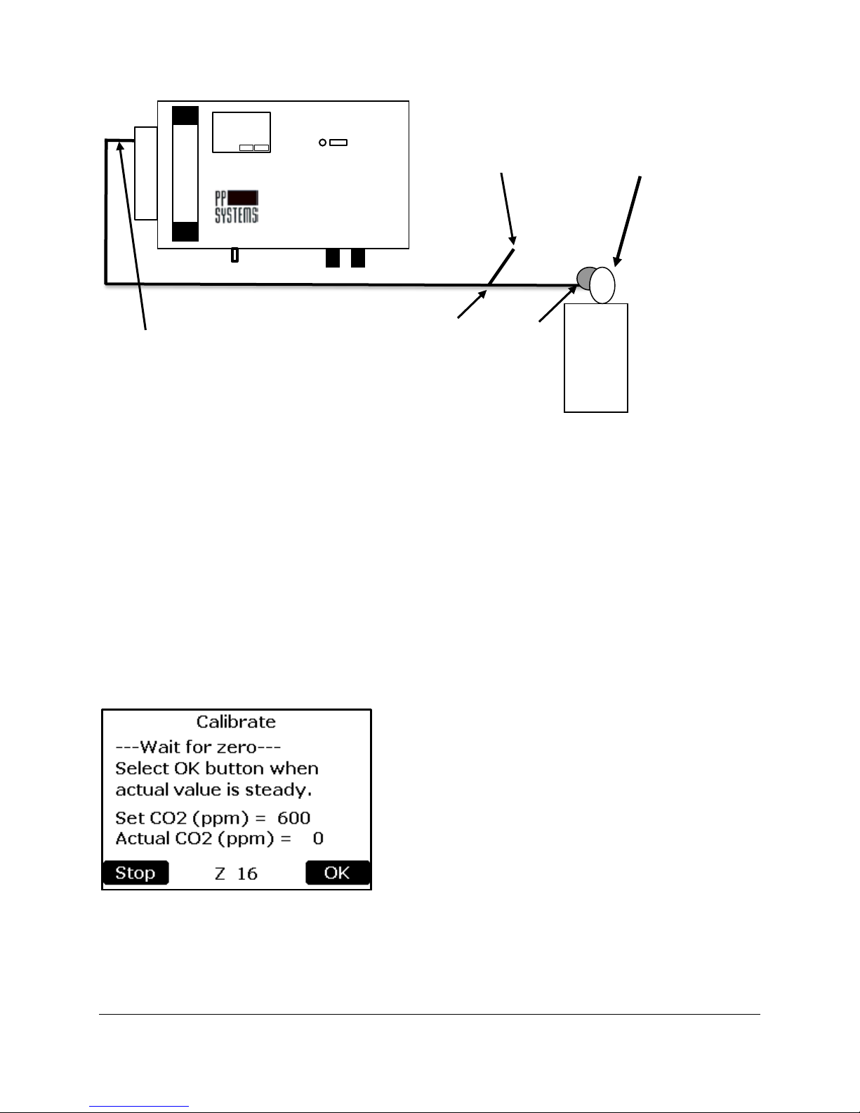
Connecting Calibration Gas to the WMA-5
During calibration, the signal from the CO2 detector is referenced against a gas of known CO2
concentration. The WMA-5 calibration procedure uses two reference points:
1. Zero CO
2. Span Gas (a user-defined CO
certified cylinder of CO
It is therefore vital that both of these references are accurate. For greater accuracy, cylinder mixtures
should be accurate to +/- 1% and traceable to NIST standards. The zero gas will only be accurate if the
soda lime in the absorber column is fresh.
Assuming that a calibration gas mixture is used to calibrate the WMA-5, follow these instructions:
1. To avoid excess pres sure in the sample c ell and pos sible dam age to the anal yzer, you m ust c onnect
the sample line with a “T” piece between the calibration gas m ixture and the gas inlet port on the
WMA-5 as follows:
(generated from air that has been scrubbed through soda lime).
2
composition).
2
concentration, normally a very accurate (+/- 1% accuracy),
2
Page 38
WMA-5
Pressure
In-line “T” piece
gas
Gas Inlet port
Shut-Off
Excess gas of
CO2
390
ppm
approx. 250 cc/min
Regulator
CO2 Analyzer
to vent excess
CO2
Gas
Valve
Cylinder
2. The pressure regulator should be s et to a ver y low press ure and there s hould be a slig ht flow exces s
gas venting from the open “T” Piece (approx. 250 ml/min).
3. Select the button to the right of the “CO
Conc (ppm):” text. The numerical keypad will appear
2
allowing a new num ber to be inputte d. See n um erical k eypad d escripti on under Zer o Tim e section f or
details.
4. Enter the CO
certified CO
concentration of the calibration gas that you are using. This value must match the
2
concentration of the calibration cylinder and be similar or higher than the anticipated
2
measurement range of the instrument (i.e. it is best to cal ibrate the instrument with a reference gas
containing 350 - 450 ppm CO
when measuring around 350 ppm CO2).
2
5. The WMA-5 will then perform a zero. At com pletion of successful zero, a similar message to the
following will be displayed.
Page 39
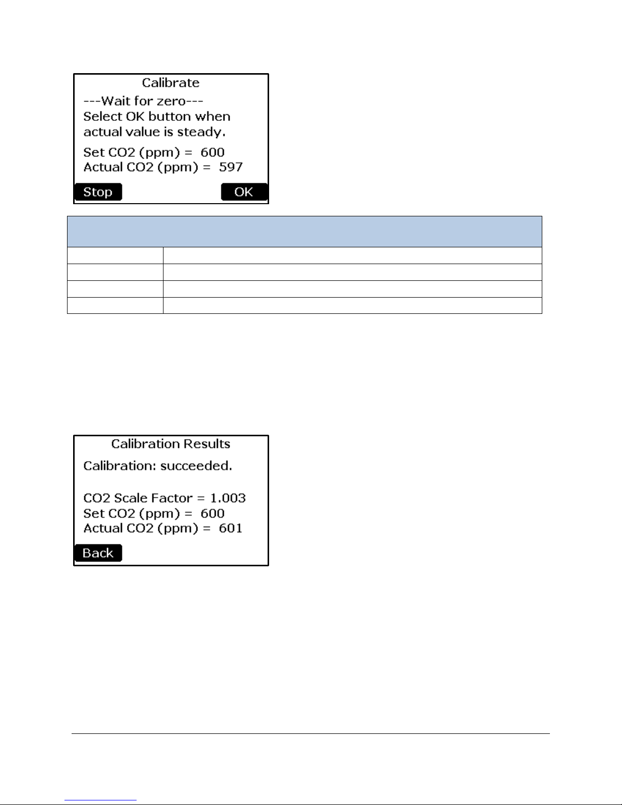
Calibration
Set CO2
The CO2 concentration value entered at the beginning of the Calibration Pr oces s .
Actual CO2
The current CO2 reading
Stop Button
Returns to the Calibration Menu with no changes.
OK Button
Calculates new Scale Factor and goes to next screen
Note, the Actual value may not be the value you entered in step 4 above. When the Actual CO2
value has stabilized ( i.e., not changing by m ore than 1 ppm after 30 seconds ), press the OK button. T o
cancel without performing a Calibration, press Stop.
If the process is successful, the screen below will be displayed and the new calibration constant will be
stored in non-volatile memory. If the process is unsuccessful, the message “Calibration: failed.” will be
displayed and no changes m ade.
The Back button returns the user back to the Main Menu.
O2 Calibration
This function allows the user to recalibrate the internal O2 Sensor used with the WMA-5.
Before calibrating, confirm that:
• The WMA-5 has been on for at least 30 minutes.
• The Gas Out port is unobstructed.
Page 40
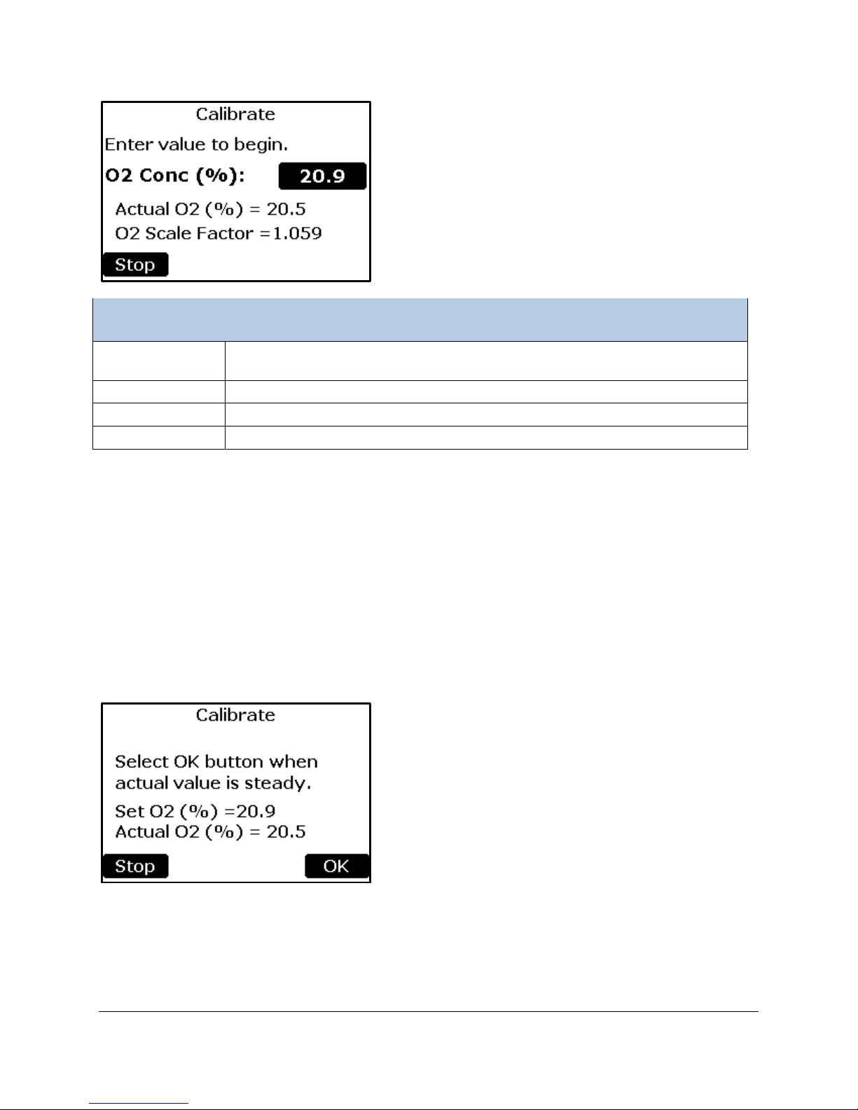
Calibration
O2 Conc Button
O2 concentration (%) of the calibration refer enc e gas.
Entering a value will begin the Calibrat ion Proc es s
Actual O2
The current O2 reading based on the Scale Factor
O2 Scale Factor
The current Scale Factor being used
Stop Button
Returns to the Calibration Menu.
Connecting Reference Gas the WMA-5
During calibration, the O2 Sensor readings are referenced against air of known O2 concentration.
Follow these instructions to calibrate the WMA-5 O
Sensor:
2
1. Connect the reference (sample) gas to the GAS IN port on the WMA-5
2. Select the button to the right of the “O
Conc (%):” text.
2
3. Enter the O
concentration of the reference gas.
2
Note, the Actual value may not be the value you entered in step 4 above. When the Actual O
has stabilized, press the OK button. To cancel without performing a Calibration, press Stop.
value
2
Page 41
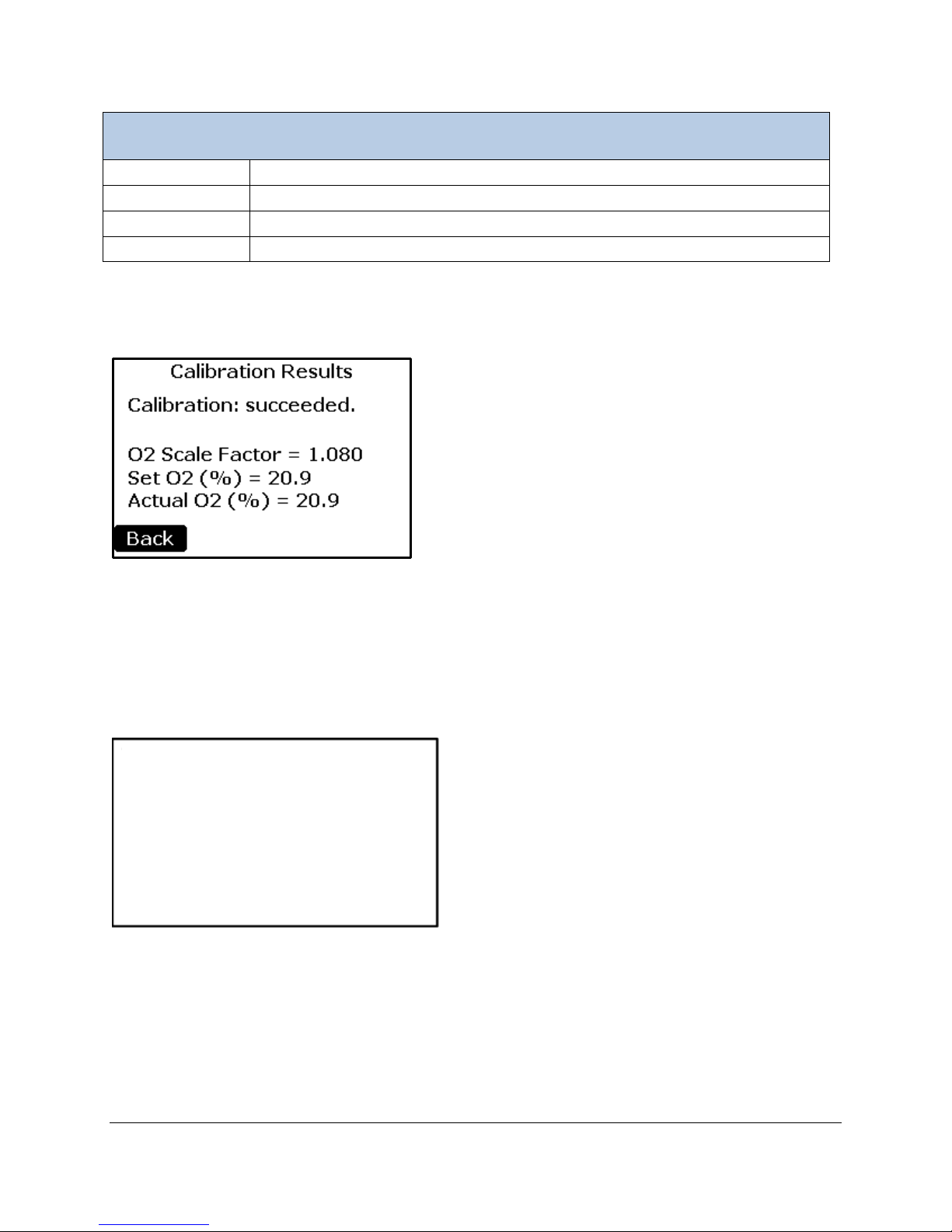
Calibration
Set O2
The O2 concentration Value entered at the beginning of the Calibration Process.
Actual O2
The current O2 Reading
Stop Button
Returns to the Calibration Menu with no changes.
OK Button
Calculates new Scale Factor and goes to next screen
Performing touch
Touch screen to
If the process is successful, the screen below will be displayed and the new calibration constant will be
stored in non-volatile memory. If the process is unsuccessful, the message “Calibration: failed.” will be
displayed and no changes m ade.
The Back button returns the user back to the Main Menu.
Touch Calibration
This function allows the user to calibrate the touch screen display. Follow the on-screen prompts to
complete the process.
screen calibration.
continue.
NOTE: This function can also be initiated by holding a finger on the screen while powering up the WMA-
5. If your touch screen is not reacting to your touch:
1. Turn the instrument off.
2. Place your finger anywhere on the touch display and turn system power on and wait for the next
screen to appear.
3. Proceed as directed with the touch screen calibration.
Page 42
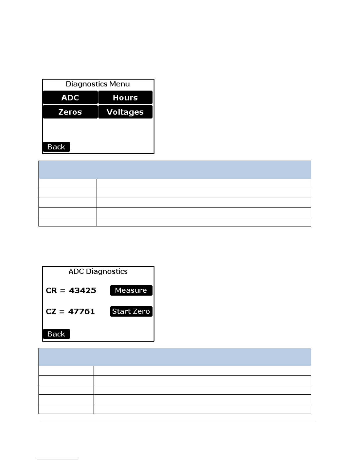
Diagnostics
Diagnostic Menu
ADC Button
To read the CO2 IRGA ADC values
Zero Button
To retrieve the last 7 zero ADC values
Hours Button
To Display the WMA-5 Hours
Voltages Button
To Display the various measured voltages
Back Button
Returns to the Main Menu.
ADC Diagnostics
CR
This is the reading from the 16 bit A/D converter for the CO2 detector.
Mode Button
To Modify the Diagnostic Modes setting. The Button displays the current mode
CZ
This is the reading from the last zero.
Start Zero Button
Initiates a zero.
Back Button
Returns the display back to the Diagnostic Menu.
This menu monitors and reports key system diagnostics associated with WMA-5 hardware. It is generally
used for troubleshooting and diagnosing potential problems associated with the instrument.
ADC Diagnostics
Page 43
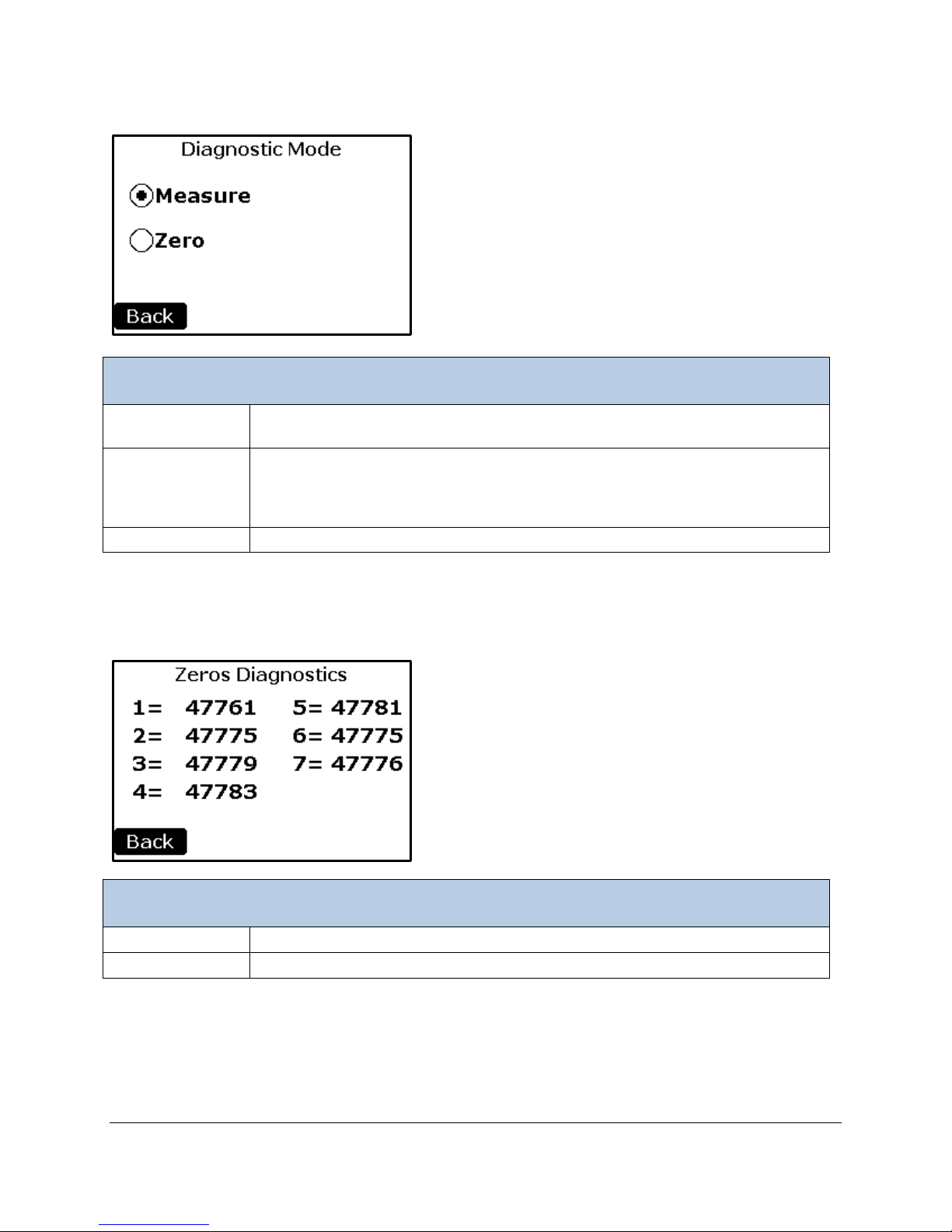
Diagnostic Mode
Diagnostics Mode
Measure Button
Puts the WMA-5 into “Measure” Mode. In “Measure” mode, the CR value should
read approximately 35000-45000 for CO2 concentration around 400 ppm.
Zero Button
Puts the WMA-5 into “Zero” mode. In “Zero” mode, the A/D value for CR should
value in “Measure” mode.
Back Button
Returns the display back to the Diagnostics display.
Zeros Diagnostics
# =
The zero ADC value of the last seven zeros
Back Button
Returns the display back to the Diagnostic Menu.
.
read approximately 40000-50000 if fresh soda lime is present in the absorber
column. The CR value in “Zero” mode should always be greater than the CR
Zeros Diagnostics
Page 44
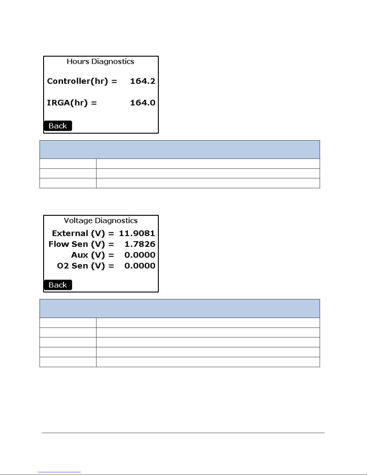
Hours Diagnostics
Hours Diagnostics
Controller (hr)
The number of Hours the WMA-5 has been Powered
IRGA (hr)
The number of Hours the CO2 IRGA has been Powered
Back Button
Returns the display back to the Diagnostic Menu.
Voltage Diagnostics
External (V)
The measured voltage powering the WMA-5
Flow Sen (V)
The voltage measured from the Flow sensor
Aux (V)
The voltage applied to the Aux input (range 0 - 1.000)
O2 Sen (V)
The voltage measured from the O2 sensor
Back Button
Returns the display back to the Diagnostic Menu.
Voltage Diagnostics
Page 45
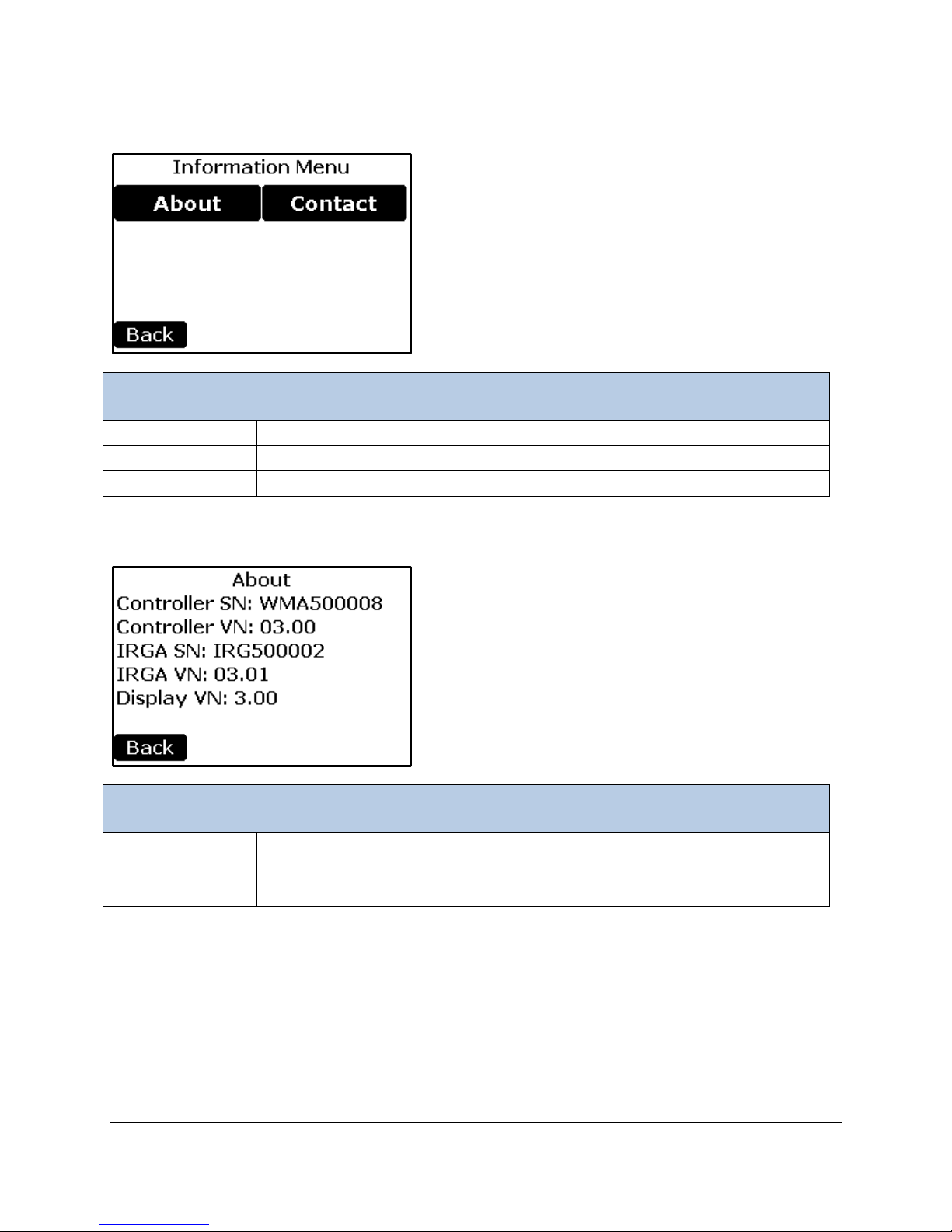
Information Menu
Information Menu
About Button
Provides information about serial numbers and the firmware versions
Contact Button
Information to contact PP Systems
Back Button
Returns to the Main Menu.
About
About
Provides important information related to the instrument hardware including
Back Button
Returns to the Information Menu.
About
serial number of the WMA-5 console.
Page 46
Contact
Contact
Contact
Contact information for PP Systems.
Back Button
Returns to the Information Menu.
Page 47

Connecting WMA-5 to External Devices
The WMA-5 has many features and options for communicating with external devices including analog,
digital, and if the WiFi option is installed, wireless.
Analog Voltage Output
One analog voltage output is available for the current CO2 reading. The full scale output is 2.5V and the
CO2 concentration corresponding to full scale can be user set in the Main > Settings > Analog Output
screen. 0 Volts always corresponds to 0 ppm CO2. The analog voltage output is located on the terminal
block at the pins labeled Vout (positive) and GND (negative).
4-20 mA Analog Current Output
One analog current output is available for the CO2 reading. The full scale output is 20 mA and the CO2
concentration corresponding to full scale can be user set in the Main > Settings > Analog Output screen.
4 mA always corresponds to 0 ppm CO2. The user must supply a fixed loop voltage of 12 to 30 VDC to
the terminal labeled Supply 4-20 mA. This supply voltage can come from an external voltage source, or
from the 12V out terminal if an external source is not desired (using a small jumper wire). An external
voltage source should be grounded to the WMA-5 ground at one of the GND terminals. The current
output is then produced between the terminal labeled Iout 4-20mA (positive) and the terminal labeled
GND (negative). A shunt resistor, often 250 Ohm, is normally used at a data logger to convert the current
output into a voltage. With a 12V supply voltage, the 4-20 mA can operate with a combined loop
resistance (shunt resistance plus cable resistance) of approximately 500 Ohm or less. With a 30V supply
voltage, the combined loop resistance can be 1200 Ohm or less.
Alarm Relay Outputs
There are two normally open relay contacts that are activated (closed) when the Low CO2 Alarm (Alarm
1) or High CO2 Alarm (Alarm 2) condition occurs. The Alarm limits are set in Main > Settings > Alarms.
The relays are rated for 30 VDC 1A or 125 VAC 0.3 A. One of the 5V out or 12V out terminals could be
jumpered to one side of these relays to get a 0 to 5V or 12V output signal to trigger an external device
such as a computer, solenoid value or, warning light.
USB Memory Stick
The USB Type A jack on the front panel is designed specifically for a USB Flash Memory Stick. Any
memory stick can be used, however the low profile memory stick provided with the WMA-5 will also allow
the enclosure cover to be closed with the memory stick installed.
It is recommend to format the memory stick to a 512 sector with 32 bit FAT for best performance.
Data collection begins when a Memory Stick is inserted into the USB port on the WMA-5. Data collection
ends when the Memory Stick is removed from the USB port. The data format used is what has been
defined for the Measure Memory Format in the Memory Measure Settings screen. The time interval used
is what has been defined for the Memory Measure Interval in the Memory Measure Settings screen.
When the memory stick is inserted the first time, a directory called “WMA5“ is created. A filename is
created within the director y using the follow in g format:
YYMMDDWI.txt
Page 48
Where,
USB cable wire color
WMA-5 Terminal block label
Black
GND
Yellow
RX 3.3V
Orange
TX 3.3V
Terminal Block Label
Data Direction
Standard PC 9 pin D connector pin
RX RS232
WMA-5 to External host
Pin 2
TX RS232
External Host to WMA-5
Pin 3
GND
-
Pin 5
YY is the last 2 digits of the clock year.
MM is the 2 digit month.
DD is the 2 digit day.
W is the WMA Id (0-9).
I is the increment of the file if there is more than one file created for a day.
Each time the memory stick is removed and then reinserted or the instrument is powered off then on, a
new file is created and the increment ‘I’ is increased.
Refer to the Error Messages for the WMA-5 table below for disk errors.
Digital Connection Methods
There are three ways to connect to the WMA-5 for viewing digital data: the USB port, the RS232 port and
the WiFi Option (if installed).
USB
A USB cable is factory installed in the WMA-5 that allows the WMA-5 to be connected to any USB host
device such as a PC, laptop or tablet. USB communication is appropriate when the connecting device is
within 2 meters of the WMA-5. This cable is connected inside the WMA-4 into the terminal block. If the
cable is removed for any reason, then reconnect the three wires as follows:
The COM port settings for the USB module to communicate with the WMA-4 controller are: 19200 baud, 8
bit, 1 stop, no parity. By default the WMA-5 is set to utilize the USB port for serial communication. If
needed, the selection of the USB port can be changed or reset in Main > Miscellaneous > More > Port.
RS232
For longer distance direct communication, a standard RS232 output is available which allows
communication with a computer or data logger up to approximately 60 meters away. The physical
connection is to the terminals labeled GND, TX RS232, and RX RS232. The port settings are 19200
baud, 8 bit, 1 stop, no parity, and no hardware or software flow control. The RS232 port is selected as
active in Main > Settings > Host Port > RS232. The USB cable must be left unconnected to a PC (or
disconnected from the WMA-5 completely) when using the RS232 interface.
Wireless
When the WiFi option is installed in the WMA-5, there are two additional connection methods available:
First, a direct wireless connection (up to 15m) between any wireless device (phone, tablet, laptop) and
the WMA-5 can be made without any additional hardware or routers. Second, the WMA-5 can be
connected to the customer’s wireless router which joins the WMA-5 into the customer’s Local Area
Network (LAN). Once the WMA-5 is connected to a LAN, any computer or device on that LAN can
access it, and potentially additional connections to any device on the Internet at large can be made if the
user’s LAN firewall and security protocols permit.
Page 49

Digital Communication Protocols and Software
Once a connection is made to the WMA-5 as described in the previous section, communication software
is needed to read, display and record data. This section describes three software programs and
protocols for utilizing WMA-5 data: WMA-5 Command Set for direct communication using WMA-5 ASCII
character strings, GAS Software for a Windows based graphical user interface with graphing and logging,
and Web Pages which are available only with the WiFi Option.
WMA-5 Command Set
When a computer is connected to the WMA-5 using either the USB cable or the RS232 port, a
communication protocol and command set comprised of ASCII characters and strings allows receipt of
WMA-5 data and setting of WMA-5 parameters. A terminal emulation program (i.e. Hyperterminal,
TeraTerm or PuTTY) is generally used for this, but other custom user software can be made to observe
and interact with the WMA-5 through these commands also.
Measured data is continuous l y output b y the WMA -5 through the currently active port (USB or RS232).
The time interval can be modified using the Host Measure Interval setting (default is every 1 second). The
data format is dependent on the Host Measure Format setting selected. See Host Measure Settings
section to modify these parameters.
Sending a command
To initiate a command, the Host (i.e. Hyperterminal) sends an ASCII string in CSV format to the WMA-5.
The command can be sent with or witho ut a CRC-8. If a CRC-8 is sent, a ‘C’ follows the CRC-8 val ue.
For example,
Host sends command without CRC-8: S,1,25<CR>
Host sends command with CRC-8: S,1,25,080C<CR>
The CRC calculation includes everything but the CRC itself and the ‘C’ character. In the example above,
the CRC was calculated from the string “S,1,25,”.
The command sent is processed by the WMA-5 after the command string terminator <CR> is received.
The command is successful if the string is under 90 characters. If a CRC-8 is present, the CRC-8 also
needs to be correct for the string to be successful.
On successfully receiving the command string, WMA-5 sends an acknowledgement by sending to the
Host a ‘+’ followed by a <CR>.
On a failure, a ‘-‘ is sent back to the Host with a <CR>.
A failure can be caused by a string longer than 90 characters or an incorrect CRC.
Receiving a response
Depending on the value of the CRC parameter (See Get/Set Parameter Values Table below), a CRC
will/will not be appended to the command received from the WMA-5. If the CRC parameter value is ‘0’
(CRC Off), no CRCs will be appended to any of the commands received from the WMA-5. If the CRC
parameter value is ‘1’ (CRC On), CRCs will be appended (including the ‘C’) to all commands received
from the WMA-5. See Get/Set Parameter Values Table for more details on turning off/on the CRC.
Page 50

For example,
WMA-5 Command Set
Command
Type
Description
*
Auto
Indicates that the device has been powered up.
Axy
Standard
This command is the diagnostic toggle for the alarm relay.
(ASCII 13).
C,d,a,c
Standard
This command calibrates the WMA-5.
e = Status Code / Error Code
With CRC=0 (CRC Off):
Received from WMA-5: G,1,25<CR>
With CRC=1 (CRC On):
Received from WMA-5: G,1,25,043C<CR>
The following table describes the WMA-5 Command Set that can be used from the Host (i.e.
Hyperterminal) to communicate with the WMA-5. Note, the examples shown below are with CRC=0 (CRC
Off). There are two types of commands; Auto and Standard. Auto commands are commands that the
WMA-5 will send out without being prompted by the user. For example, the ‘W’ (Warm Up) command is
only sent by the WMA-5 when it is warming up. Standard commands are commands that are sent by the
user. <CR> represents a carriage return (ASCII 13).
WMA-5 Command Set Table
x=’1’ for ALARM1
x=’2’ for ALARM2
y=’0’ for Alarm Off
y=’1’ for Alarm On
Example:
Sent from Host: A11<CR>
Received from WMA-5:
+<CR>
A11
In this example, ALARM1 would be set to on. <CR> represents a carriage return
d = device
1 = CO
2 = O
Irga
2
sensor
2
a = Action
0 = Calibrate
1 = Reset to 1.0
2 = read Current Factor
c = Calibration Value
Returned String:
C,d,a,c,f,e<CR>
f = New Calibration Factor
Page 51

0 = Success
10 = Bad Format
E,xxx
Auto
This command transmits any errors. See Error Messages for the WMA-5 Table below
In this example, 11 is the Low Alarm error.
Fx
Standard
This command sets the Zero Valve.
In this example, Zero Valve would be set to on.
G,x
Standard
This command gets a parameter stored in EEPROM (non-volatile memory). The value
In this example, the value of Zero Type is 1 (Automatic).
Mx
Standard
This command performs a “one shot” output. Each time the ‘Mx’ is called one set of
value of x determines where the data will be sent:
11 = Device parameter incorrect
12 = Action parameter incorrect
13 = Calibration value (CO
14 = Calibration factor (CO
) out of range
2
) out of range
2
15 = Calibration failed
16 = Calibration value (O
17 = Calibration factor (O
) out of range
2
) out of range
2
Example:
1. Calibrate to CO
to 2000ppm
2
Example:
Sent from Host: C,1,0,2000<CR>
Received from WMA-5:
+<CR>
C,1,0,2000,1.091,0<CR>
In the example, the CO
reading is 2000 and the calibration factor is 1.091.
2
for more details.
Example,
Received from WMA-5:
+<CR>
E,11<CR>
x=’0’ Off
x=’1’ On
Example:
Sent from Host: F1<CR>
Received from WMA-5:
+<CR>
F1
x is the number associated with a particular parameter (See Get/Set Parameter Values
Table below). When Gx is sent from the Host, the value associated with that particular
parameter is returned.
Example:
Sent from Host: G,1<CR> (Get Zero Type)
Received from WMA-5:
+<CR>
G,1,1.000<CR>
data is displayed in the format that was selected previously (i.e., M1, M2, etc.). The
Page 52

H=Host
had been set to 3. See Get/Set Parameter Values Table below for more details.
N
Standard
This command returns five system voltage measurements in volts. External Voltage,
AUX1 Voltage=0.0000 and O2 Sensor Voltage=0.0000.
S,x,v
Standard
This command sets a parameter in EEPROM (non-volatile memory). The value of x is
In this example, Zero Type is set to 1 (Automatic).
T
Standard
This command gets and sets the time in the 24 hour format. The command can be
M=Memory Stick
W=Wireless
A=All three
Example:
Sent from Host: MH<CR>
Received from WMA-5:
+<CR>
M3,1,0003,17,12,15,27,1095,0.0,20.41,327,0.0000,55.0, 1002.9,0x0000<CR>
In this example, the data is sent to the Host only. The Host Measure Format setting
System Voltage, Flow Sensor Voltage, AUX1 Voltage and O2 Sensor Voltage are sent
in order in CSV format.
Example:
Sent from Host: N<CR>
Received from WMA-5:
+<CR>
N,12.1324, 6.6143, 0.4765, 0.0000, 0.0000<CR>
In this example,
External Voltage=12.1324, System Voltage=6.6143, Flow Sensor Voltage=0.4765,
the number associated with a particular setting and v is the desired value of the
particular setting. The value of v is saved in the EEProm. A ‘G’ command is returned to
confirm the change requested. See Get/Set Parameter Values Table below.
Example:
Sent from Host: S,1,1<CR>
Received from WMA-5:
+<CR>
G,1,1.00<CR>
implemented in three different ways.
1. Get values: The ‘T’ command is used to get the complete set of day/time values.
Example:
Sent from Host: T<CR>
Received from WMA-5:
+<CR>
T,04,42,15,05,01,15<CR>
In this example, seconds=04, minutes=42, hour=15, day=05, month=01 and
year=(20)15.
2. A Full Set: The ‘T’ command can also be used to set the complete set of day/time
values.
Page 53

Example:
Current time: T,04,42,15,05,01,15<CR>
same.
V
Standard
This command returns the serial numbers and software versions of the WMA-5
IRGA version number=01.02
W
Auto
During warm up of the WMA-5, the W command is transmitted every second until the
Where in this example, 55.0 is the IRGA temperature (°C).
X
Standard
This command retrieves last seven zeros performed.
The last seven zeros are displayed.
Z
Z,xxx
Auto &
Standard
This command initiates a zero. During a zero operation, the WMA-5 transmits every 1
seconds the Z command until the end of the zero operation. (No “M” strings are sent
Sent from Host: T,04,42,10,05,02,15<CR>
Received from WMA-5:
+<CR>
T,04,42,10,05,02,15<CR>
In this example, hour is changed from 15 to 10 and month is changed from 1 to 2.
If any one of the attributes is different from the current the value, it will be updated.
3. A Partial Set: The ‘T’ command can be used to set particular attributes of the
day/time values using 1-6, where 1=seconds, 2=minutes, 3=hour, 4=day, 5=month
and 6=last 2 digits of year.
Example:
Current time: T,4,42,10,05,02,15<CR>
Sent from Host: T,3,11<CR>
Received from WMA-5:
+<CR>
T,4,42,11,05,02,15<CR>
In this example, the hour was changed from 10 to 11. All other values stayed the
controller, the IRGA and the Display.
Example:
Sent from Host: V<CR>
Received from WMA-5:
+<CR>
V,WMA500007,01.02,IRGA00001,01.02<CR>
Where, in this example,
WMA-5 serial number= WMA500007
WMA-5 version number=01.02
IRGA serial number=IRGA00001
operating temperature is reached. (No “M” strings are sent during this time)
Example:
Received from WMA-5:
W,55.0<CR>
Example:
Sent from Host: X<CR>
Received from WMA-5:
+<CR>
X, 44200, 44223, 49971, 49972, 49976, 49981, 49973<CR>
Page 54
during this time). This command can be initiated by the user or by the WMA-5 itself.
counts down of the number of cycles remaining.
Get/Set Parameter Values
Number
(X)
Parameter
Name
Description
Valid
Values
Default Value
1
Zero Type
See Zero Settings section. The
Set, 3=Manual
1-3
1 (Automatic)
2
Zero Time (min)
See Zero Settings section.
1-40
20
3
Average Limit
(ppm)
See Averaging Settings section.
0-100
30
4
Alarm Low (ppm)
See Alarm Settings section.
0-1000
250
5
Alarm High (ppm)
See Alarm Settings section.
100-20000
2000
6
Alarm Sound
See Alarm Sound section.
0=Off;
1=On
0 (Off)
7
CO2
(ppm)
See Analog Output Settings
100-
2000
8
WMA ID
See WMA ID section.
0-9
1
9
Pump Power (%)
Percentage of the pump power (i.e.,
air flow).
0-100
60%
10
Host Measure
Format
See Host Measure Settings section.
1-6
3 (Full format)
11
Host Measure
See Host Measure Settings section.
broadcast.
0-3600
1 second
12
Memory Measure
Format
See Memory Format Settings
section.
1-6
3 (Full format)
13
Memory Measure
Interval (seconds)
See Memory Measure Settings
section.
0-3600
1 second
14
WIFI Measure
Format
See WIFI Measure Settings section
1-6
2 (No header
format)
15
WIFI Measure
Interval (seconds)
See WIFI Measure Settings section.
0-3600
0 seconds (Manual)
16
Not Used
17
CRC
Determines whether a CRC-8 will
works for the Host only.
0=Off;
0 (Off)
18
Web Monitor
Adds counter and terminator to
for web pages
0=Off;
1 (On)
Example:
Sent from Host: Z<CR>
Received from WMA-5:
+<CR>
Z, 025<CR>
Z, 024<CR>
…
A zero has been initiated by the user. In this example, xxx is 025 then 024 which
Get/Set Parameter Values Table
values are: 1=Automatic, 2=User
Concentration
Interval (seconds)
section.
Use ‘0’ for manual mode to stop
be appended to each command
received from the WMA-5. This
strings sent to the WiFi Port to use
100000
1=On
1=On
Page 55
19
Host Serial Port
Selects the Host serial port.
’0’ USB (TTL serial 3.3v)
voltage levels)
0=USB
0 USB
GAS
GAS
’1’ RS232 (compliant RS232
1=RS232
GAS (Gas Analysis Software)
PP Systems Windows® based GAS (Gas Analysis Software) software is available for displaying and
logging data from the WMA-5. No programming or command-line knowledge is required to utilize the GAS
software. Connection between the WMA-5 and computer is via the USB interface. GAS will run on
Windows XP and above.
The GAS software is included on the flash drive that comes with each new instrument (Part No. xxxxx),
under the “PC Utilities\GAS_v[x]” directory, where [x] is the version number. GAS is also available for
download directly from our website (for registered users only). To install GAS, double click on “setup.exe”.
A number of standard installation windows will be shown to guide you through the installation process.
Once GAS is installed, the following icon will appear on the desktop:
Double click this icon to start GAS.
Click Choose Device and choose WMA-5.
A new WMA-5 tab window will appear. Next, click the Connect button.
Page 56
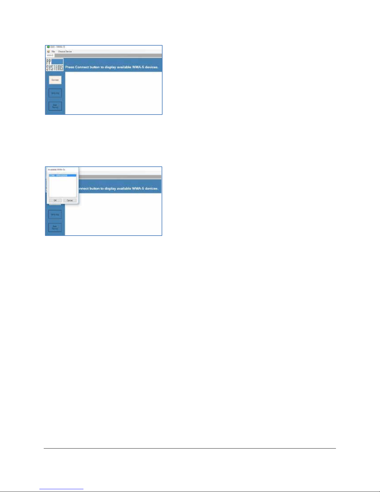
In the top left corner, a box will appear listing all available WMA-5 devices. Select one and click OK.
After clicking OK, the main measurement screen will be displayed.
Page 57
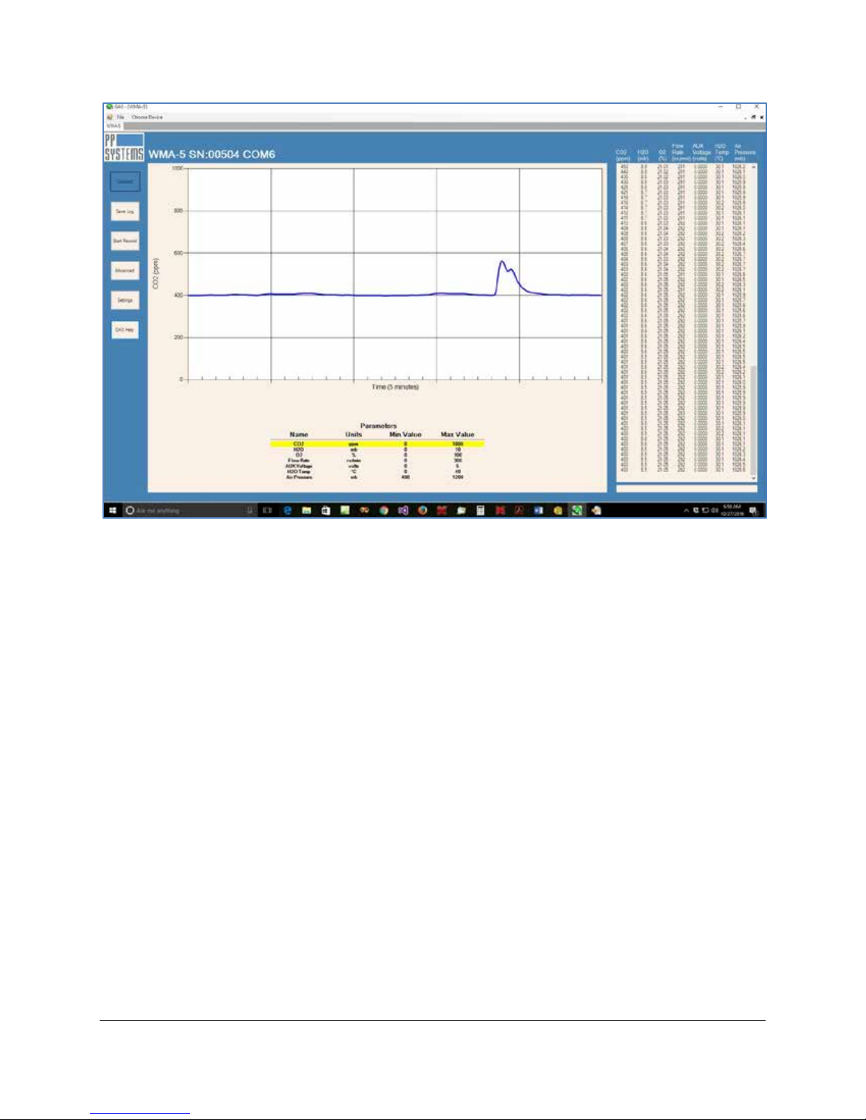
Note: In the top left area, the device name (e.g., TARGAS-1, EGM-5, SBA-5 or WMA-5), serial number,
and COM port are all displayed. Data is displayed both graphically and numerically. GAS gives the ability
to log past data activity in a current session (Save Log) or record data (Start Record) for a time segment.
Clicking the Advanced button will show a command-line window for sending commands directly to and
from the WMA-5. The Settings button allows the user to modify the parameters’ minimum and maximum
values. Data is saved in comma-delimited .txt files. A graphical representation of each parameter can be
seen by clicking the parameter name in the table below the graph. The highlighted parameter will be
displayed on the graph.
For more detailed information on the functionality of GAS, refer to “Gas Help” under the Help menu in the
software.
Page 58
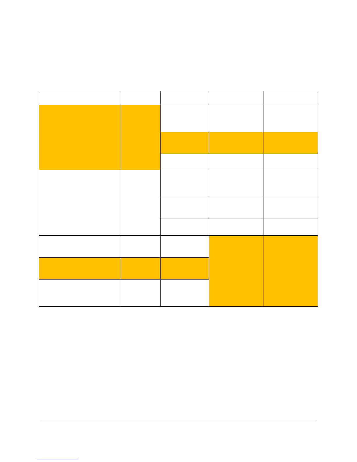
Communication Summary
Connection to WMA-5
Typical
Distance
Receiving
Device
Software
Result
Data strings displayed
command strings
Any Windows XP
USB host port
PP Systems GAS (Gas
Custom interface to
loggers
Data strings displayed
command strings
Any Windows XP
serial port
PP Systems GAS (Gas
Custom interface to
loggers
Any wireless device
Android)
Any device on the
Android)
Wireless (WiFi) – Client Mode
external access)
The following table summarizes the communication methods and protocols described in the preceding
sections. In addition, other capabilities exist within the WiFi option that may be useful to some users
attempting to write custom code on a wireless connection – please contact PP Systems for more
information.
USB 0-2 meter
RS232 0-60 meter
Wireless (WiFi) – Soft Access Point
(no router required)
Wireless (WiFi) – Client Mode
(WMA-5 connected to LAN via
existing router)
(WMA-5 connected to LAN via
existing router, AND the router
firewall is configured to allow
0-15 meter
LAN extent
Worldwide
Any USB host
device (PC, laptop,
iPad)
and above
computer with a
Any USB host
device
Any device with a
serial port
and above
computer with a
Any serial device Custom user code
with a browser (PC,
iPad, iPhone,
LAN with a browser
(PC, iPad, iPhone,
Any device in the
world with a
browser
Any terminal emulation
program such as
HyperTerminal,
TeraTerm, PuTTY
Analysis Software)
Custom user code
Any terminal emulation
program such as
HyperTerminal,
TeraTerm, PuTTY
Analysis Software)
Any browser (Internet
Explorer, Firefox,
Chrome, Safari)
in real time,
Able to change WMA-5
settings with simple
Graphical display of
data, and data logging
user equipment or data
in real time,
Able to change WMA-5
settings with simple
Graphical display of
data, and data logging
user equipment or data
View WMA-5 web
pages with live data
and trend. Able to
change wireless
settings, but not WMA5 settings.
Notes:
• USB and RS232 can not be used simultaneously.
• Highlighted blocks are the expected use methods for most customers.
Wireless Network Settings
The WMA-5 Wi-Fi embedded device server contains two network interfaces. The Software enabled
Access Point interface (SoftAP) is also called ap0, and the wireless local area network interface (WLAN)
is called wlan0.
A maximum of four clients can be connected to the SoftAP interface if the WLAN interface is disabled. If
the WLAN interface is enabled a maximum of three clients may be connected.
Page 59

The wireless network settings show the status of the Software-enabled Access Point (SoftAP) or WLAN
interface/link and let you configure the settings on the device. Interface settings are related to the
configuration of the IP and related protocols. Link settings are related to the physical link connection,
which carries the IP traffic.
Note: All network settings require a reboot to take effect. Wait a minimum of 20 seconds after rebooting
the unit before attempting to make any subsequent connections. (Reboot the WiFi hardware from
Wireless Settings > Device > Reboot menu item, or just power cycle the WMA-5.)
Connecting To WMA-5 Via Direct Wireless Connection
Here are the steps to make a wireless connection to the WMA-5 using the Soft Access Point (Soft AP)
mode that is the easiest and simplest WiFi connection for the WMA-5. The WMA-5 acts as an access
point for a wireless device, and no other equipment is required. This is also the default connection
method enabled after a factory reset, and users must use this connection mode to change the settings for
other modes.
1. By default the SoftAP mode is enabled with a default SSID of ‘WMA5’.
2. Use the Wi-Fi Connection Manager of your connecting device (phone, tablet, laptop, etc ) to scan for
available wireless networks, and above SSID should be presented as a choice. Select the SSID and
follow the device connection manager instructions to continue to connect. (Note: if more than one
WMA-5 is powered on within the wireless range of one another, and each WMA-5 defaults to the
SSID of ‘W MA5’, it will be dif f icult to determine which WMA-5 is connected to the wireless device.
When more than one WMA-5 is to be used, it is recommended to power on only one WMA-5 at a time
at first, then change the SSID as described in step 8 below to a unique name that eliminates the
duplicate SSIDs.)
3. The default security for WMA5 Wi-Fi SoftAP is WPA2 and the passphrase is ‘PPSYSTEMS’. These
defaults can be changed through the configuration web manager after the initial connection has been
established.
4. When prompted enter the passphrase to complete the Wi-Fi connection authentication process. With
a Wi-Fi client set to the above parameters, your device can connect directly to the WMA-5 Wi-Fi Soft
AP.
5. Open a standard browser (E.g. Internet Explorer®, Firefox®, Chrome™, Safari® etc.) and in the
address field of the browser enter ‘192.168.0.1’ as the IP address. Some browsers interpret that
address as a search term rather than a LAN IP address, so enter ‘http://192.168.0.1’ in the address
bar, if necessary.
6. When prompted, enter the username of ‘admin’ and password ‘PASSWORD’ to access the WMA-5
Web pages. At this point, the WMA-5 Splash Screen will be displayed in the browser window. Click
the Main button to advance to the 3 data screens of WMA-5 data continually updated with live data.
7. If it is desired to change any of the wireless network settings, go to web management page Main >
Settings > Yes
8. Select Network > ap0 > Link to get to the Status/Configuration page for the SSID, Securi t y Suite
Type and Security and passphrase. Modification to any of these parameters requires first pressing
the Configuration button, then a reset/power cycle of the module in order to take effect.
Page 60
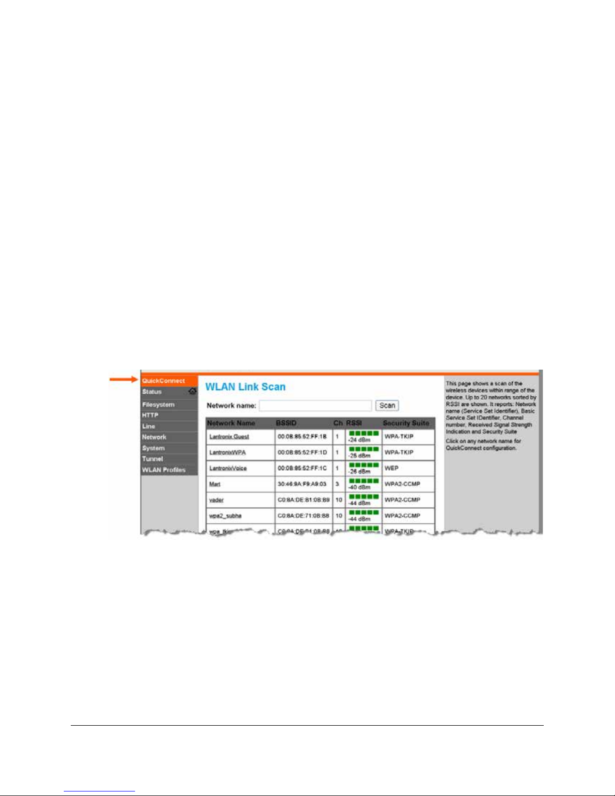
It is recommended that you record any changes you make.
SSID: ________________________________________
Security Suite: ________________________________
Encryption: ___________________________________
Passphrase: __________________________________
Connecting to WMA-5 via a Local Area Network
Here are the steps to make a wireless connection to the WMA-5 using the Client Mode method in which
the WMA-5 is connected to a user’s existing Local Area Network via a user’s existing wireless access
point or wireless router. Once the WMA-5 is joined to the LAN, any computer or wireless device that is
also joined to the LAN can view the WMA-5 web pages.
1. First, connect to the WMA-5 using the SoftAP method described above from any wireless device.
Then navigate to the Wireless Network Settings (Main > Settings > Yes).
2. WLAN QuickConnect: QuickConnect offers the ability to configure the STA (WLAN Client)
interface on WMA-5 WiFi to establish connection to an active Access Point. QuickConnect learns
most of the connection properties from the available Access Points and prompts the user only for
the security parameters and saves the settings under a corresponding new/existing WLAN profile
for future autonomous operation of the WLAN Client interface.
3. Upon selection of the QuickConnect option, the WMA-5 Wi-Fi scans and displays up to 20
wireless devices in order of strongest signal strength at the top. Click on a network name to view
the connection to that desired Access Point.
Page 61
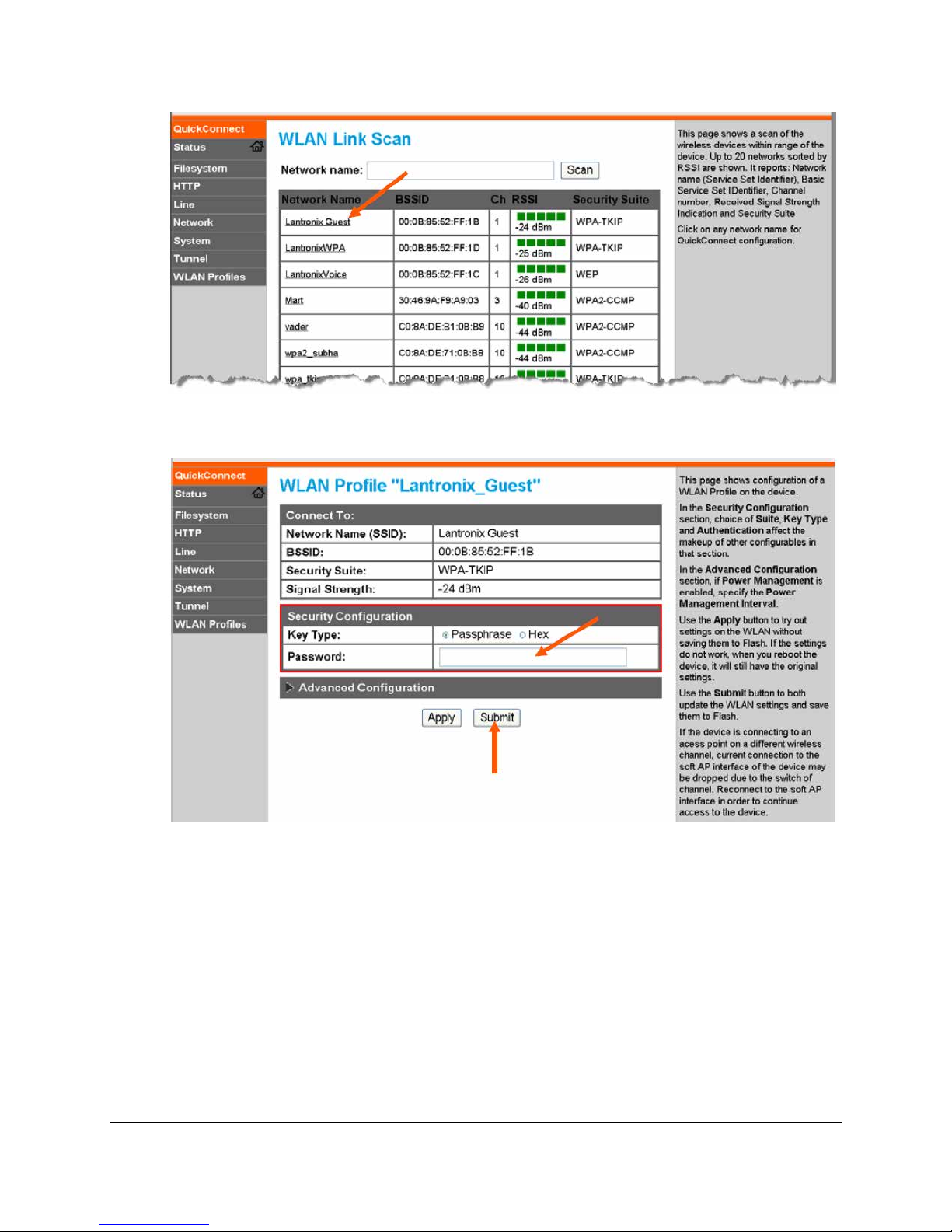
4. When the selected Access Point profile displays, enter the password and click Submit to directly
connect to the Access Point and to add the profile and conf igur at ion det ai ls to the WLAN profiles.
5. Once added, the Quick Connect profile is connected and is accessible and configurable through
WLAN Profiles.
6. Then, once the WMA-5 is successfully connected a LAN, view the Status page under the
Interface wlan0 section to see the particular IP address that was assigned to the WMA-5. In the
example below, the LAN IP address 10.0.0.150 was assigned to the WMA-5 (and the softAP
Interface ap0 address is still available for direct connection at 192.168.0.1). The LAN-assigned
IP address can be changed from time-to-time by the LAN router, but the ap0 address will always
be 192.168.0.1.
Page 62
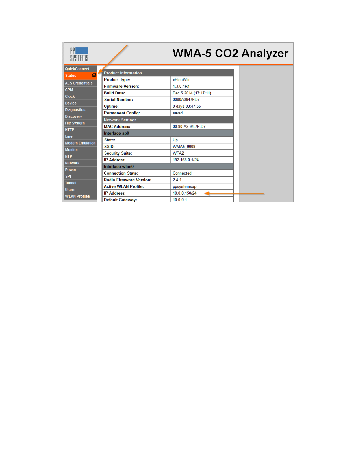
7. Now, any computer on the LAN can open a standard b r owser ( E.g. Intern et Expl orer ®, Firef ox ®,
Chrome™, Safari® etc.) and in the address field of the browser enter IP address assigned to the
WMA-5, such as ‘10.0.0.150’ for the example shown. Some browsers interpret that address as a
search term rather than a LAN IP address, so enter ‘http://10.0.0.150’ in the address bar, if
necessary. Then, follow the steps 6, 7 and 8 from the SoftAP section above to enter the user
name and password and navigate through the WMA-5 web pages.
Page 63

Measure Format Settings Table
Measure Format Setting
Setting
Description
M1
M1 is the legacy data format used in the WMA-4 (previous model to the WMA-5).
below for details. (position 51,52)
M2
M2 is the No Header format contains everything but the header and is comma
WMA-5 table below for details.
M3
M3 is the full format that has the complete data set and is comma delimited.
This table describes the six different Measure Formats. Note: In the examples, there CRC parameter is
turned off and there are no CRCs concatenated to the end of a message. <CR> represents a carriage
return (ASCII 13).
Note: this format is NOT comma delimited.
An example is:
M1100012801131900968115025000000000000000000000099700<CR>
The format is as follows:
M1: Determines what data format is being displayed. In this case, M1 is WMA-4
format. (position 0,1)
WMA ID: 0-9. (Identifier for WMA-5 when multiple units are used). (position 2)
Record #: 1-9999. (position 3-6)
Day: 1-31. (position 7,8)
Month: 1-12 (January - December). (position 9,10)
Hour: 1-24 (based on 24 hour clock). (pos ition 11, 12)
Minutes: 0-59. (position 13,14)
CO2 Ref: CO
mb Ref: H
AnT: Temperature ( °C) of the gas sample. (position 23-26)
Input 1: millivolts (mV) signal from sensor connected to AUX1. (position 27-30)
Input 2: millivolts (mV) signal from sensor connected to AUX2. (position 31-34)
Input 3: not used. Value is 0000. (position 35-38)
Input 4: not used. Value is 0000. (position 39-42)
Input 5: not used. Value is 0000. (position 43-46)
ATMP: Atmospheric pressure in millibars (mb). (position 47-50)
ECode: Displays error code message. See Error Messages for the WMA-5 table
reading in parts per million (ppm = µmol m2 s-1). (position 15-19)
2
O reading in millibars (mb). (position 20-22)
2
delimited.
An example is:
M2, 1094, 0.0, 20.41, 327, 0.0000, 55.0, 1004.2,0x0000<CR>
The format is as follows:
M2: Determines what data format is being displayed. In this case M2 is No Header
format.
(ppm): CO2 reading in parts per million (ppm = µmol m2 s-1)
CO
2
0 (mb): H2O reading
H
2
(%): O2 reading
O
2
Flow Rate (cc/min): Rate of flow.
Aux Voltage (volts): AUX1.
0 Sensor Temperature (°C): Temperature of the gas sample.
H
2
Air Pressure (mb): Atmospheric pressure
System Error (hex): Displays error code message. See Error Messages for the
Page 64

An example is:
M3,1,0003,17,12,15,27,1095,0.0,20.41,327,0.0000,55.0, 1002.9,0x0000<CR>
WMA-5 table below for details.
M4
M4 is the short format is an abbreviated version of the data and is comma
WMA-5 table below for details.
M5
M5 is the fast format (every 0.1 seconds), is a minimized version of the data and is
WMA-5 table below for details.
M6
M6 is the raw format contains raw data (A/D values) from the IRGA. It is comma
M6: Determines what data format is being displayed. In this case M6 is Raw
The format is as follows:
M3: Determines what data format is being displayed. In this case M3 is Full format.
WMA-id: 0-9 (Identifier for WMA-5 when multiple units are used).
Record #: 1-9999
Day: 1-31
Month: 1-12 (January - December).
Hour: 1-24 (based on 24 hour clock).
Minute: 0-59
(ppm): CO2 reading in parts per million (ppm = µmol m2 s-1)
CO
2
0 (mb): H2O reading
H
2
(%): O2 reading
O
2
Flow Rate (cc/min): Rate of flow.
Aux Voltage (volts): AUX1
0 Sensor Temperature (°C): Temperature of the gas sample.
H
2
Air Pressure (mb): Atmospheric pressure
System Error (hex): Displays error code message. See Error Messages for the
delimited.
An example is:
M4,1096,327,55.0,1002.9,0x0000<CR>
The format is as follows:
M4: Determines what data format is being displayed. In this case M4 is Short
format.
(ppm): CO2 reading in parts per million (ppm = µmol m2 s-1)
CO
2
Flow Rate (cc/min): Rate of flow.
0 Sensor Temperature (C): Temperature of the IRGA.
H
2
Air Pressure (mb): Atmospheric pressure
System Error (hex): Displays error code message. See Error Messages for the
comma delimited.
An example is:
M5,1094.07,0x0000<CR>
The format is as follows:
M5: Determines what data format is being displayed. In this case M5 is Fast format
which is 0.1 seconds.
(ppm): CO2 reading in parts per million (ppm = µmol m2 s-1)
CO
2
System Error (hex): Displays error code message. See Error Messages for the
delimited.
An example is:
M6, 44572, 50675, 17603, 17600, 37340, 50292,0x0040<CR>
Where <CR> represents a carriage return (ASCII 13)
The format is as follows:
Page 65
format.
CO2: Relates to the CO2 reading.
Displays IRGA error code message as a hexadecimal number.
Air Pressure: Relates to the atmospheric pressure reading.
Temperature Sensor1: Relates to temperature sensor 1.
Temperature Sensor2: Relates to temperature sensor 2.
Lamp: Relates to lamp current.
Last Zero CO
: Reports last zero value.
2
Page 66
Error Messages for the WMA-5 Table
Error Messages
Error
Code
Status Box
Message
Description
10
Low Zero Error
Zero read to low (<2500).
11
Low Alarm Error
CO2 less than 250 ppm (default).
12
High Alarm Error
CO2 greater than 2000 ppm (default).
13
Under Temp Error
Analyzer temperature < 50 oC.
14
Over Temp Error
Analyzer temperature > 60 oC.
15
Low Flow Error
The flow is less than 50.
16
IRGA EEProm Write
Fail
IRGA unable to perform a write. If error persists, call PP Systems
technical support.
17
IRGA EEProm CRC
Fail
IRGA read/write EEProm CRC incorrect. If error persists, call PP
Systems technical support.
18
IRGA Out of Range
IRGA setting error. Value is out of range. If error persists, call PP
Systems technical support.
30
Unknown Command
Host only. First character is not recognized as a command.
Example is just sending a <CR>.
31
Invalid Format
Host only. First character is a recognized command but the next
character is invalid. Example: S1,1<CR>.
32
Invalid Parameter
Host only. Command is correct but parameter is not. Example:
S,20,5. The value of 20 is an invalid parameter.
33
Low Range Limit
Host Only. Value entered is below the valid range of values for that
parameter.
34
High Range Limit
Host Only. Value entered is above the valid range of valu es for that
parameter.
50
Disk ND
Disk related error. No disk has been detected.
51
Disk CF
Disk related error. Command failed – Filename or directory name not
found.
52
Disk BC
Disk related error. Bad command – Command not recognized.
53
Disk DF
Disk related error. Disk full – No free space on disk.
54
Disk FI
Disk related error. Invalid – Attempt to open a directory for reading or
writing. Attempt to change currently selected directory to a file.
55
Disk RO
Disk related error. Read only – Attempt to open a read only file for
writing.
56
Disk FO
Disk related error. File open – A file is currently open for writing and
must be closed before this command can be executed.
57
Disk NE
Disk related error. Directory not empty – Attempt to delete a directory
which is not empty.
58
Disk FN
Disk related error. Filename invalid – Firmware invalid or contains
disallowed characters.
60
Disk NU
Disk related message. No upgrade – Firmware upgrade file not found
on disk. This message is seen each time a disk is inserted into the
Error and status messages are displayed in the Status Box during operation.
The following table highlights the most common messages that you may see from time to time:
Page 67

drive.
61
Disk DD
Disk related message. Disk detected - This message is seen each
time a disk is inserted into the drive.
62
Disk DR
Disk related message. Disk removed - This message is seen each
time a disk is removed from the drive.
Page 68
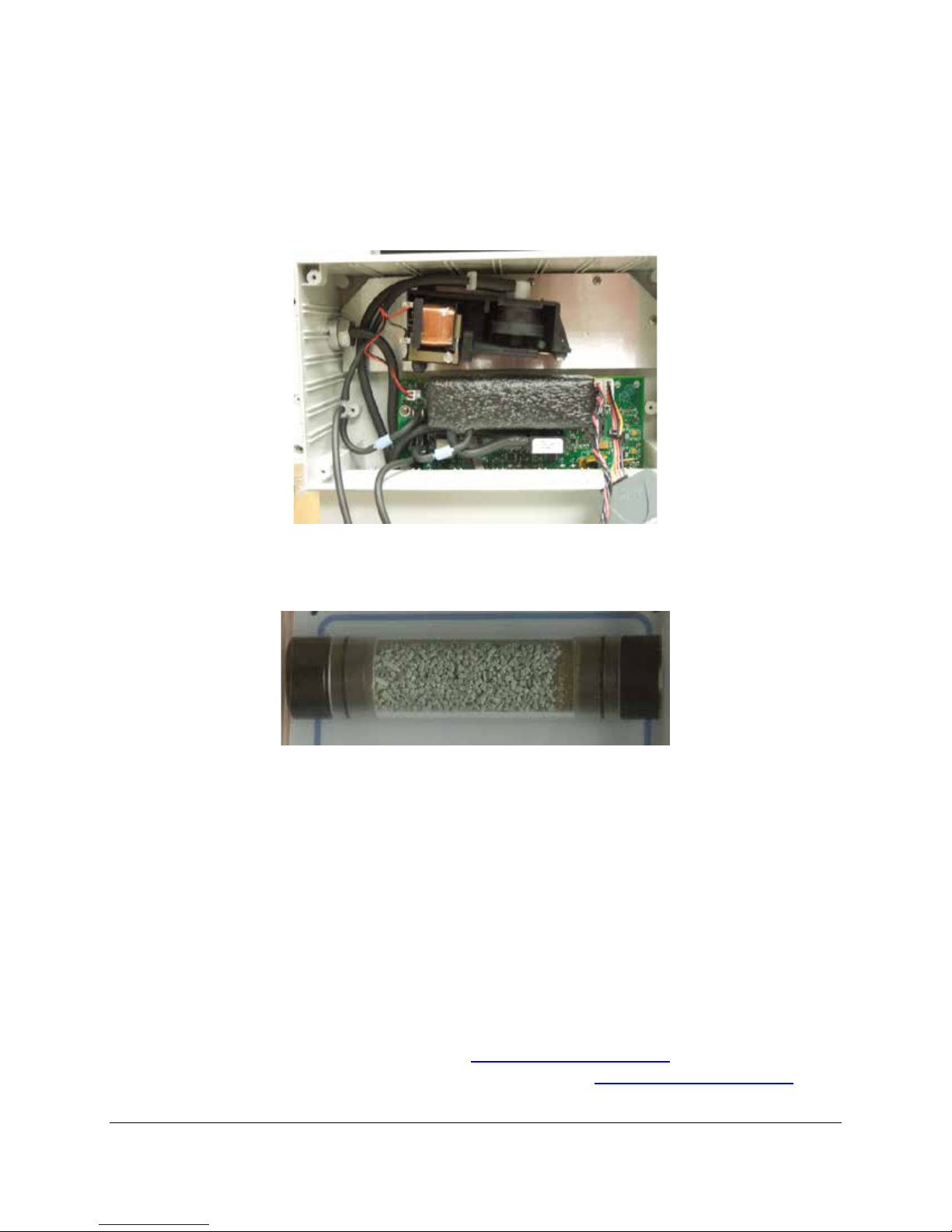
Maintenance
The WMA-5 requires minimal maintenance and access to internal components should not be required
with the exception of the internal hydrophobic filter which does require periodic replacement (See
Hydrophobic Filter on page 70). To access internal IRGA components, remove the 4 screws in each
corner of the main front panel and gently pull off.
Absorber Column and CO2 Scrubber
Periodically inspect the condition of the following items:
Soda Lime
• The soda lime should last for 2-3 months from the time it is replaced. PP Systems used to supply
a “green to brown” indicating soda lime but this type is no longer available and has since been
replaced by the “white to violet” indicating soda lime. For most applications running at low CO2
concentrations (i.e. less than 2000 ppm) the indicator is not very strong and you may not see any
obvious change in color. So the rule of thumb should be to pay attention to the CO
reset (see Reset Zero Absorber on page 27) function or simply change out the soda lime once
every month if you have any questions about its freshness.
Soda Lime cannot be regenerated and should be discarded after exhaustion.
• Type: Sofnolime, 1.0-2.5 mm, self-indicating (white to violet), 1 kg
• Manufacturer: Molecular Products. (www.molecularproducts.com
• For the latest Material Safe t y Data Sheet, ple as e visit www.molecularproducts.com and
request the latest MSDS or contact PP S ystems.
)
absorber
2
Page 69
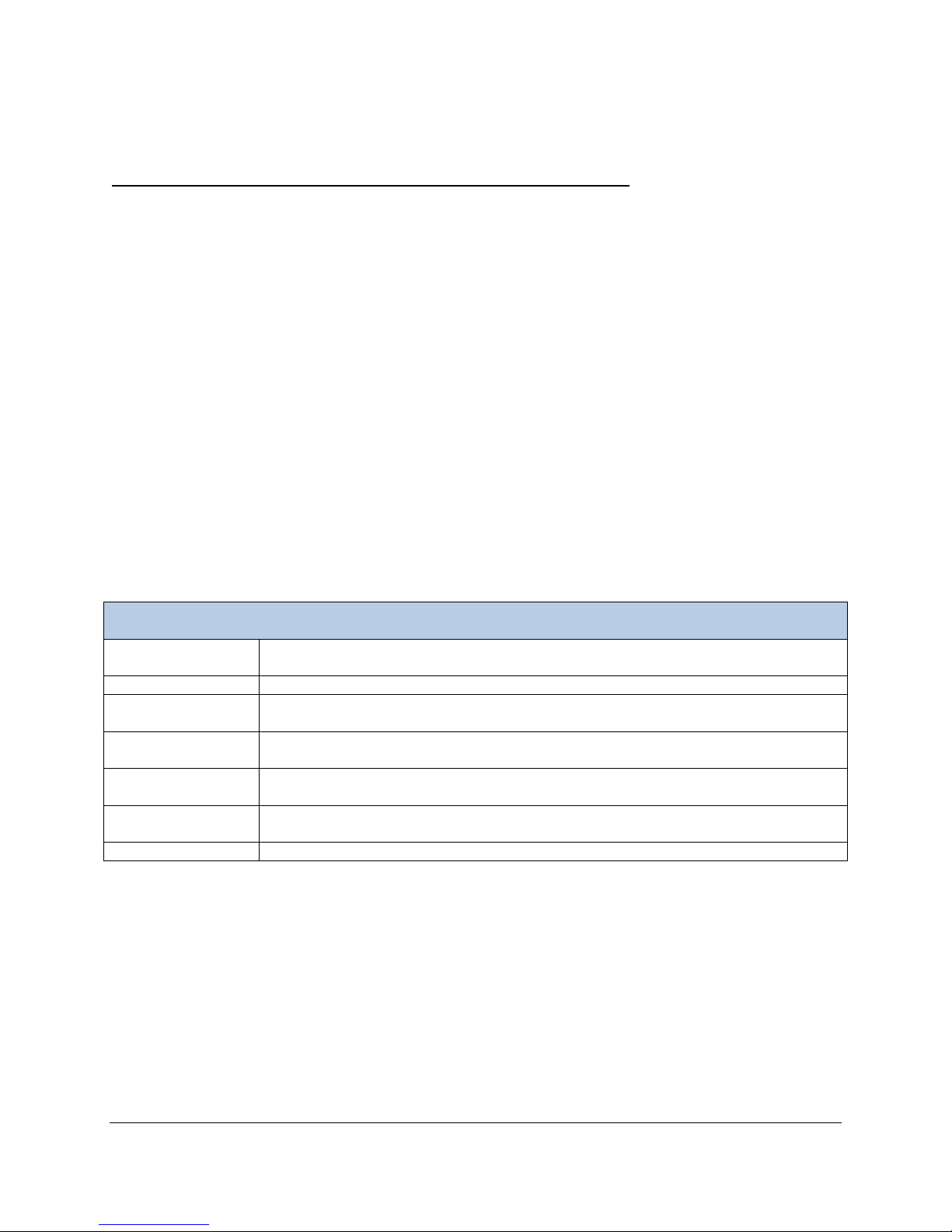
For the latest MSDS on alternative types of soda lime, please contact the manufacturer directly or contact
Re-Order Information
Part Number
Description
10164-1
WMA-5 Absorber Column (Complete)
20041-2
Absorber Column (clear plastic only)
41508-1
Gray Filter Foam
30013-1
O-ring 4.47 x 1.78
30013-17
O-ring 17.6 x 2.4
STD007W
Sofnolime (white to violet), 1 kg
PP Systems
Take caution to wash your hands comple tely after handling soda lime.
Gray Foam Filters
• The gray foam filters used inside the absorber column (top and bottom) will wear over time and
should be inspected regularly and replaced when torn or reduced in size. The foam must be of an
open celled type, such as packing foam. The foam filters at the bottom of each column will likely
require more frequent changes versus the upper foam filters.
Absorber Filters
• Each absorber end cap contains a white pl as tic filter disk. Generally these do not need to be
replaced but should be checked periodically. However, they must be present to prevent any of the
column contents being drawn with the gas stream causing damage to the instrument.
End Cap “O” Rings
• Each end cap has two “O” rings, one that seals inside the plastic column and another that seals
at the manifold. All “O” Rings on the absorber column should periodically (every couple of weeks)
receive a slight smear of silicone grease to aid ease of fitting, improve the seal and extend the life
of the “O” rings and to keep them from cracking or breaking. Once sealed, end fittings should be
checked to ensure that the O-rings are seated correctly in their groove and that they are not
trapped or pinched resulting in system leaks.
Page 70
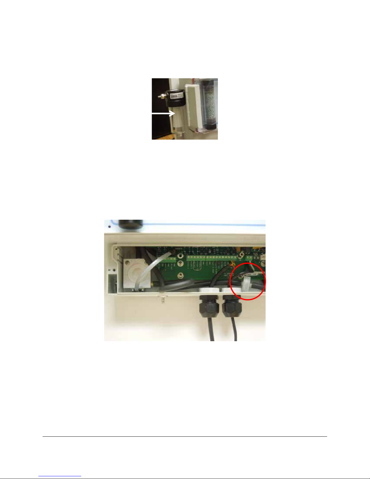
Water Trap
Grip glass section with
required
The water trap (also referred to as a “Float Valve Housing”) is an essential filtration tool when gas is being
drawn to the CO
analyzer preventing the carry-over of water from getting into the system.
2
your hand and turn
counter-clockwise to
empty water as
Periodically inspect the water trap for water and empty as required. To empty, turn the glass counterclockwise to remove from the black section at the top and empty. Inspect the “O” ring on the glass piece
periodically and make sure it has a slight smear of silicone grease to aid ease of fitting, improve the seal
and extend the life of the “O” ring and to keep it from cracking or breaking.
Hydrophobic Filter
An internal hydrophobic filter (Part No. 10045-1) is located inside the smaller terminal block enclosure. It
is secured in place by the black viton tubing.
This should be replaced periodically based on environmental conditions. If sampling in dry environments,
we recommend replacing the filter once every 3 months. If sampling in high humidity environments we
recommend that you change it more frequently (once per month). To change, gently pull one end of the
filter assembly from the gas tubing and then repeat on the other side. Connect new filter assembly to the
tubing and reassemble.
Page 71

Sampling Pump
The sampling pump used in the WMA-5 is a vibrating diaphragm type pump. It operates from 12 VAC
that is generated onboard from the WMA-5 12V DC power supply. It is capable of delivering flow rates up
to 500 cc/min flow. History has shown that this style pump is extremely rugged and durable and should
last for many years. If replacement is necessary, please contact PP Systems.
Infrared Source
The infrared source should last for many years and not require replacement. The obvious sign of failure
is that it is not flashing when the system is powered. It is preferable to return the instrument to PP
Systems for full factory recalibration after changing a failed source lamp. However, if that is not possible,
a few checks can be made to insure that the analyzer is working properly after changing a source lamp in
the field. Please contact PP Systems for more information.
Page 72
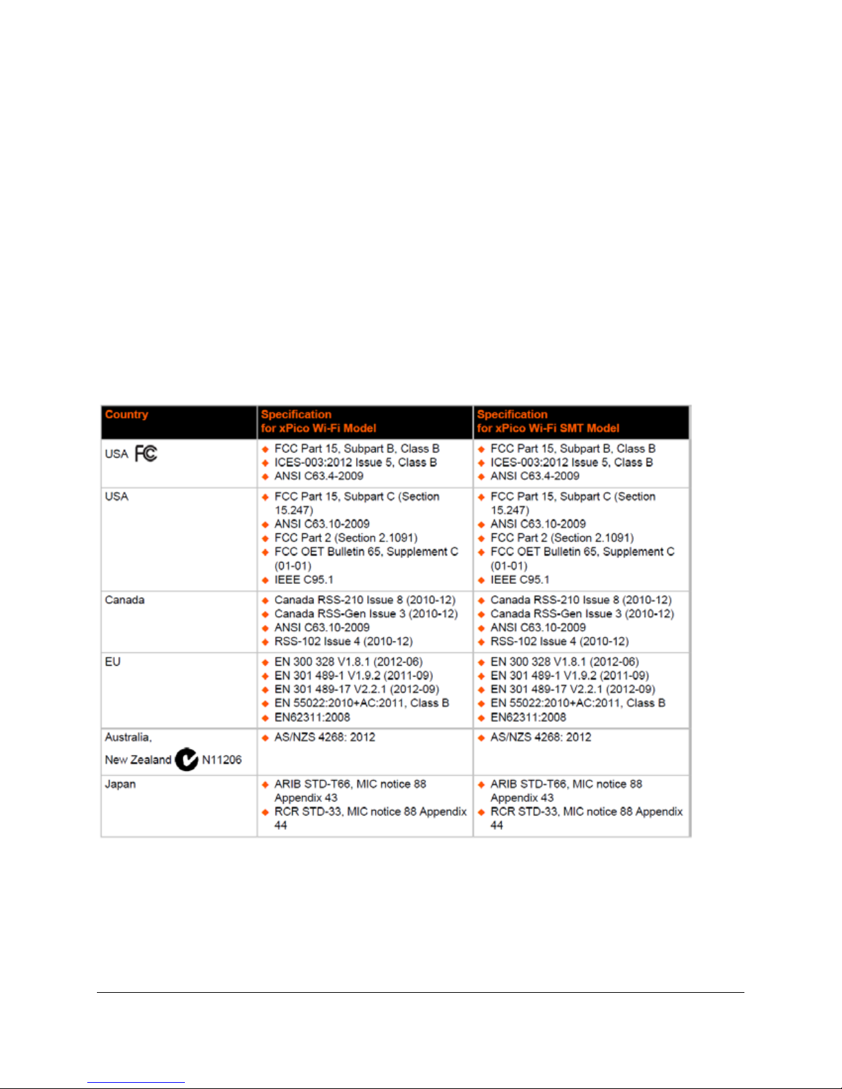
Appendix 1. WiFi Compliance
The Wireless device used in the WMA-5 is a product from Lantronix and is their xPico® Wi-Fi®
Embedded Device Server
(According to ISO/IEC Guide and EN 45014)
Manufacturer's Name & Address:
Lantronix, Inc.
167 Technology Drive, Irvine, CA 92618 USA
Declares that the following product:
Product Name Models:
xPico® Wi-Fi® Embedded Device Server, xPico Wi-Fi SMT Embedded Device Server Conforms to the
following standards or other normative documents:
Table C-1 Country Certifications
Page 73
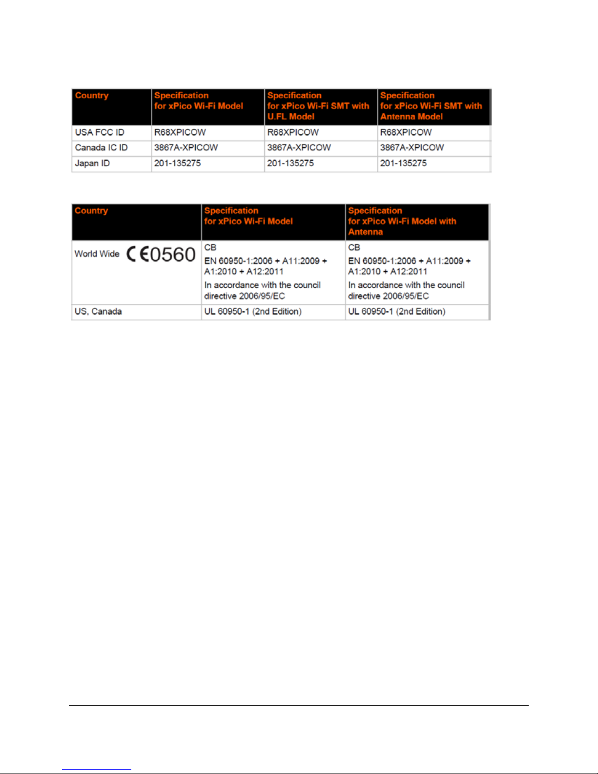
Table C-2 Country Transmitter Ids
Table C-3 Safety
Hereby, Lantronix, declares that this xPico Wi-Fi and xPico Wi-Fi SMT embedded device server is in
compliance with the essential requirements and other relevant provisions of Directive 1999/5/ EC.
Federal Communication Commission Interference Statement
This device complies with Part 15 of the FCC Rules. Operation is subject to the following two conditions:
(1) This device may not cause harmful interference, and (2) this device must accept any interference
received, including interference that may cause undesired operation. This equipment has been tested and
found to comply with the limits for a Class B digital device, pursuant to Part 15 of the FCC Rules. These
limits are designed to provide reasonable protection against harmful interference in a residential
installation. This equipment generates, uses and can radiate radio frequency energy and, if not installed
and used in accordance with the instructions, may cause harmful interference to radio communications.
However, there is no guarantee that interference will not occur in a particular installation. If this equipment
does cause harmful interference to radio or television reception, which can be determined by turning the
equipment off and on, the user is encouraged to try to correct the interference by one of the following
measures:
• Reorient or relocate the receiving antenna.
• Increase the separation between the equipment and receiver.
• Connect the equipment into an outlet on a circuit different from that to which the receiver is
connected.
• Consult the dealer or an experienced radio/TV technician for help.
FCC Caution: Any changes or modifications not expressly approved by the party responsible for
compliance could void the user's authority to operate this equipment.
This transmitter must not be co-located or operati ng in conj unc tion w ith any other antenna or transmitter.
Page 74

Radiation Exposure Statement
This equipment complies with FCC radiation exposure limits set forth for an uncontrolled environment.
This equipment should be installed and operated with minimum distance 20cm between the radiator &
your body.
 Loading...