

PP Systems Inc.
110 Haverhill Road, Suite 301
Amesbury, MA 01913 U.S.A.
Tel: +1 978 834-0505
Fax: +1 978 834-0545
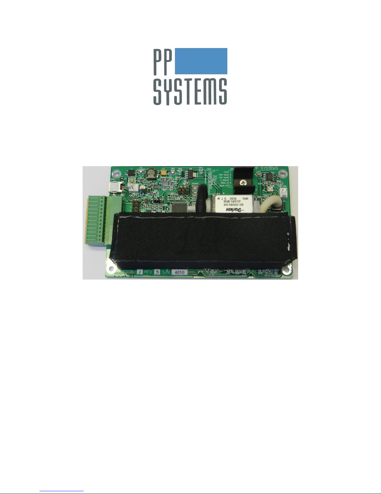
SBA-5 CO2 Analyzer
Version 1.06
© 2015 PP Systems. All Rights Reserved
04 November 2015
Email: support@ppsystems.com
Web Site: http://www.ppsystems.com


This page is left intentionally blank.

Table of Contents
Table of Contents
Table of Contents ................................................................................................ 4
Preface ................................................................................................................. 6
Notice ................................................................................................................. 6
Documentation Conventions .............................................................................. 6
User Registration ............................................................................................... 6
Service & Warranty ............................................................................................ 7
Contact Information ............................................................................................ 7
Unpacking Your Equipment ............................................................................... 7
Technical Specification ...................................................................................... 8
Introduction & Overview .................................................................................. 10
Measurement Principle .................................................................................... 10
Powering up the SBA-5 .................................................................................... 10
Operation ................................................................................................................................ 10
SBA-5 Warm-up ..................................................................................................................... 11
Power Input connector (CN2) ................................................................................................. 11
Input/Output and RS-232Terminal Block (CN3) ..................................................................... 11
Input/Output Header (CN4) .................................................................................................... 12
Indicating LEDs ...................................................................................................................... 12
Installation ........................................................................................................ 12
Mounting the SBA-5 ......................................................................................... 13
SBA-5 Gas Circuit ............................................................................................ 14
SBA-5 CO2 Gas Analyzer with Enclosure ....................................................... 15
Gas Connection ............................................................................................... 15
Terminal Block on Enclosure ........................................................................... 16
SBA-5 Recalibration ......................................................................................... 17
Recalibration Procedure .................................................................................. 17
SBA-5 Communication ..................................................................................... 18
RS-232 Connection and Setup ........................................................................ 18
Spare I/O Line .................................................................................................. 18
4-20 mA Output ................................................................................................ 19
USB Connection and Setup ............................................................................. 19
Command Summary ........................................................................................ 20
Measurement Commands ................................................................................ 20
Measurement Command Response ................................................................ 21
Measurement String Format Command: .......................................................... 21
Zero Valve Related Commands ....................................................................... 22
CO2 Related Commands ................................................................................. 23
Other Commands ............................................................................................. 24
Command Files ................................................................................................ 25
Upgrading SBA-5 Firmware ............................................................................. 26
SBA-5 CO2 Analyzer Operation Manual – Version 1.06
- 4 -

Preface
Maintenance ...................................................................................................... 27
Absorber Column ............................................................................................. 27
Absorber Column Foam Pads ................................................................................................ 27
Absorber Column Filters ......................................................................................................... 27
Absorber Column “O” Rings. .................................................................................................. 27
Soda Lime ........................................................................................................ 28
MATERIAL SAFETY DATA FOR SODA LIME ...................................................................... 28
Servicing The SBA-5 ......................................................................................... 30
Pump ............................................................................................................... 30
Removing a Pump .................................................................................................................. 30
Servicing a Rotary Vane Pump .............................................................................................. 30
Infrared Source ................................................................................................ 31
Zero Valve ....................................................................................................... 31
User Notes ......................................................................................................... 32
SBA-5 CO2 Analyzer Operation Manual – Version 1.06
- 5 -

Preface
Preface
Notice
This equipment must not be used in situations where its failure could result in injury or death.
For applications where failure of this equipment to function correctly would lead to consequential
damage, the equipment must be checked for correct operation and calibration at intervals
appropriate to the criticality of the situation.
PP Systems' equipment warranty is limited to replacement of defective components, and does
not cover injury to persons or property or other consequential damage.
This manual is provided to help you install and operate the equipment. Every effort has been
made to ensure that the information contained in this manual is accurate and complete. PP
Systems does not accept any liability for losses or damages resulting from the use of this
information.
It is extremely important that you take the time to review this Operator’s Manual prior to
installation and operation of the equipment. Otherwise, damage may be caused which is not
covered under our normal warranty policy.
This manual, and the information contained in it, is copyright to PP Systems. No part of the
manual may be copied, stored, transmitted or reproduced in any way or by any means including,
but not limited to, photocopying, photography, magnetic or other mechanical or electrical means,
without the prior written consent of PP Systems.
All brand/product names are trademarks of their respective owners.
Documentation Conventions
If viewed electronically, text marked blue acts as Hyperlinks.
User Registration
It is very important that ALL new customers register themselves with us to ensure that our user’s
list is kept up to date. If you are a PP Systems’ user, please register yourself electronically on our
web site at:
http://www.ppsystems.com/user_registration2.htm
Only REGISTERED users will be allowed access to our protected “Users” section of our web site.
This section will contain important product information including hardware/software updates,
application notes, newsletters, etc.
Thank you in advance for your cooperation.
SBA-5 CO2 Analyzer Operation Manual – Version 1.06
- 6 -

Preface
Service & Warranty
PP Systems' equipment warranty is limited to replacement of defective components, and does
not cover injury to persons or property or other consequential damage.
The equipment is covered under warranty for one complete year, parts and labour included. This,
of course, is provided that the equipment is properly installed, operated and maintained in
accordance with written instructions (i.e. Operator's Manual).
The warranty excludes all defects in equipment caused by incorrect installation, operation
or maintenance, misuse, alterati on, and/ or accident.
If for some reason, a fault is covered under warranty, it is the responsibility of the customer to
return the goods to PP Systems or an authorised agent for repair or replacement of the defective
part(s).
Contact Information
PP Systems, Inc.
110 Haverhill Rd, Suite 301
Amesbury, MA 01913
USA
Tel: 978-834-0505
Fax: 978-834-0545
Sales: sales@ppsystems.com
Support: support@ppsystems.com
Service: service@ppsystems.com
Unpacking Your Equipment
It is extremely important that you check the contents of your equipment immediately upon receipt
to ensure that your order is complete and that it has arrived safely. Please refer to the checklist
supplied (if applicable) for a detailed list of spares and accessories that are included with your
order.
DO NOT DISCARD ANY OF THE PACKAGING MATERIAL UNTIL ALL OF THE ITEMS
LISTED ARE ACCOUNTED FOR.
WE RECOMMEND THAT YOU RETAIN THE ORIGINAL PACKING FOR FUTURE USE.
If you suspect that any of the items listed on the appropriate checklist are not included or
damaged, you must contact PP Systems or authorised distributor immediately.
SBA-5 CO2 Analyzer Operation Manual – Version 1.06
- 7 -

Technical Specification
Technical Specification
Analysis Method
Non-dispersive infrared, configured as an absolute absorptiometer with microprocessor control of
linearization.
CO2 Measurement Ranges
0-1,000 ppm (umol mol-1) / 0.1%
0-2,000 ppm (umol mol
0-5,000 ppm (umol mol
0-10,000 ppm (umol mol
0-20,000 ppm (umol mol
0-30,000 ppm (umol mol
0-50,000 ppm (umol mol
0-100,000 ppm (umol mol
Custom ranges up to 100,000 ppm upon request. Measurements are automatically corrected for
temperature and pressure.
Pressure Compensation Range
80-115 kPa
Accuracy
<1% of span concentration over the calibrated range but limited by the accuracy of the
calibration gas mixture.
Linearity
<1% throughout the range.
Stability
Automatic zero at regular intervals corrects for sample cell contamination, source and
detector aging and pre-amplifier gain changes.
Gas Flow Rate Through Analyzer
Range: 100-1,000 cc/min (Maximum)
We recommend 200-500 cc/min
Calibration
User programmable calibration (if required)
Analog Output
Dual 0-5V linear (CO
4-20 mA (CO
Digital Interface
RS-232 (Terminal block)
USB (Miniature 5 pin)
Humidity Sensor Input
Power Supply
6-18 VDC
-1
) / 0.2%
-1
) / 0.3%
-1
-1
-1
-1
only)
2
) / 1%
) / 2%
) / 3%
) / 5%
-1
) / 10%
and H2O)
2
SBA-5 CO2 Analyzer Operation Manual – Version 1.06
- 8 -

Technical Specification
Power Consumption
~9 W (warm-up)
~1-3 W (normal operation and depend ent on ambient temperature)
Gas Connections
Two barbed fittings (inlet and exhaust) for use with 1/8” (.125”) ID tubing
PCB Type
FR4
Operating Temperature Range
-20°C to +50°C
Relative Humidity Range
0-95% RH, non-condensing
Dimensions
7.5 cm W x 12 cm L x 3.5 cm H
(SBA-5 PCB only)
8 cm W x 13 cm L x 4.5 cm H
(SBA-5 with enclosure)
Weight
0.2 kg (SBA-5 PCB onl y)
0.4 kg (SBA-5 with enclosu r e)
Optional Accessories
Sampling pump (Part No. STD105)
Absorber column (Part No. STD509)
Humidity sensor (Part No. STD547)
Enclosure (Part No. AGA407 and AGA408)
- Includes the SBA-5
PP Systems is continuously updating its products and reserves the right to amend product
specifications without notice.
All brand/product names are trademarks of their respective owners.
SBA-5 CO2 Analyzer Operation Manual – Version 1.06
- 9 -

Introduction & Overview
Introduction & Overview
Measurement Principle
The SBA-5 OEM CO2 Analyzer is a non-dispersive, infrared gas analyzer that features an “AutoZero” facility. Using infrared gas analysis techniques, we can readily determine CO
Dioxide) concentrations to within a few ppm and instantaneous measurements are possible.
Gases with di-atomic molecules such as CO
, one region of strong absorption is 4.26 microns. A source (IR source) emitting strongly at
CO
2
strongly absorbs photons in the infrared range. For
2
this wavelength is a light bulb. If this is positioned at one end of a tube and at the other end is a
sensor that is sensitive to photons at 4.26 microns, we have a simple infrared gas analyzer. As
is passed down the sample cell, it absorbs some of the infrared and the sensor reading
CO
2
decreases. The “Auto-Zero” feature, which occurs at regular intervals, allows for fast warm-up,
adaptation to changing ambient conditions and excellent stability of the CO
signal. The action of
2
auto-zeroing minimizes the effects on span (gas sensitivity) of sample cell contamination, source
aging, changes in detector sensitivity and changes in pre-amplifier gain. By default and after
system warm-up, the SBA-5 will perform “Auto-Zeros” every 20 minutes. The “Auto-Zero” interval
can be changed by the user if required up to a maximum of 10,000 minutes. PP Systems highly
recommends that the SBA-5 performs frequent “Auto-Zeros” to ensure accuracy and
reliability of data.
The SBA-5 features automatic temperature and pressure compensation.
The SBA-5 is supplied as a calibrated CO
optical bench (to a specified range) fitted to an FR4
2
type printed circuit board (PCB). All components are located on the board.
(Carbon
2
Powering up the SBA-5
The SBA-5 requires a 6-18V DC input to power up the analyzer. Power can be applied to 3
different connectors on the SBA-5 board (CN2, CN3 or CN4). See sections below for appropriate
connections.
Operation
Once the SBA-5 is connected to a proper power supply and immediately after it is powered up,
there is a short pause and then the IR source lamp starts to flash. If the RS-232 or USB line is
connected to a PC running a terminal program (i.e. Hyperterminal on older PC’s and
HyperAccess on more recent PC’s), the following information is transmitted:
EEPROM OK
B, SBA5,nnnn, x.xx
Where: B= Begin
nnnn= serial number
x.xx= EPROM version number
The SBA-5 temperature is checked until it stabilizes near 55
W, nn
Where: W=Warm up delay
nn= Temperature
o
C with the following transmitted:
SBA-5 CO2 Analyzer Operation Manual – Version 1.06
- 10 -

Introduction & Overview
Pin Number
Name
DescriptionDescription
1
VIN
Power In 6-18 V
2
GND
Power and Signal Ground
Pin Number
Name
DescriptionDescription
1
VIN
Power In 6-18 V
2
GND
Power and Signal Ground
3
CO2VOUT
CO2 Analog Output Voltage
4
H2OVOUT
H2O Analog Output Voltage
5
4-20OUT
4-20 mA Current Output. See 4-20 mA
Output on page 19.
6
ZREQIN
Zero Request (momentarily ground to
force a zero sequence)
7
SPAREIO
See Spare I/O Line on page 18.
8
GND
Power and Signal Ground
9
GND
Power and Signal Ground
10
TX
RS-232 TX to PC Serial Port D9-2
11
RX
RS-232 RX from PC Serial Port D9-3
12
GND
RS-232 Ground to PC Serial Port D9-5
This is then followed by an analyzer ZERO with the following transmitted:
Z, nn of 12
Where: Z= Zero
nn= the count up to 12
At count number 7, a click will be heard as the valve switches to measure mode. The remaining
time is allowed for flushing out the sample cell until the instrument has reached its operating
temperature of 55
o
C and performed the first ZERO.
SBA-5 Warm-up
We recommend allowing the SBA-5 to warm up for at least 30 minutes to ensure best operation.
For the first 10-15 minutes, warm-up messages are output via digital lines (RS232 and USB).
After approximately 15 minutes, CO2 sensor data starts to get output via the digital lines. In
approximately 30 minutes and after the system achieves thermal stability and records several
good analyzer zeros, the SBA-5 should be stable and ready for use.
Power Input connector (CN2)
Connector on board is Molex 22-11-2022.
Input/Output and RS-232Terminal Block (CN3)
The terminal block connector is a Phoenix Contact 1881545 and the mating connector is a
Phoenix Contact 1881422 pluggable push-in wire terminal block.
SBA-5 CO2 Analyzer Operation Manual – Version 1.06
- 11 -

Introduction & Overview
Pin Number
Name
DescriptionDescription
1
VIN
Power In 6-18 V
2
GND
Power and Signal Ground
3
CO2VOUT
CO2 Analog Output Voltage
4
GND
Power and Signal Ground
5
H2OVOUT
H2O Analog Output Voltage
6
GND
Power and Signal Ground
7
4-20OUT
4-20 mA Current Output. See 4-20 mA
Output on page 19.
8
GND
Power and Signal Ground
9
ZREQIN
Zero Request (momentarily ground to
force a zero sequence)
10
GND
Power and Signal Ground
11
SPAREIO
See Spare I/O Line on page 18.
12
GND
Power and Signal Ground
LED1 HB
Represents the ‘heartbeat’ of the SBA-5. It
operating properly.
LED2 USB
Represents the Universal Serial Bus. It is
communication is established.
Input/Output Header (CN4)
Standard 0.1 inch 12 pin double row male header. (These signals duplicate the signal on the
terminal block).
Indicating LEDs
There are a couple of LEDs located on the SBA-5 board to assist with system troubleshooting:
flashes at 5 Hz indicating that the system is
illuminated when a USB cable is connected and
Refer to Mounting the SBA-5 on page 13 for location of the LEDs.
Installation
The SBA-5 is a high precision CO2 analyzer designed for users that want to incorporate it into
existing systems. For best results, we recommend building the SBA-5 into an enclosure to
ensure good thermal stability. It can be used for use in monitoring/controlling CO
greenhouses, environment control rooms, nurseries, IAQ, process control and industrial
applications. Long term stability and accuracy is ensured as a result of our unique “Auto-Zero”
technology.
A suitable sampling pump delivering 300-1,000 cc/min of sample air is also required for normal
operation. PP Systems can supply an optional sampling pump (Part No. STD105) if required.
The sampling pump is connected to CN8 and the pump speed can be adjusted manually by
potentiometer P1 (see next page for location) if required. If the sampling pump is supplied by PP
Systems, the flow rate is set at 300 cc/min.
in
2
SBA-5 CO2 Analyzer Operation Manual – Version 1.06
- 12 -

Introduction & Overview
0.0 [0.000]
5.5 [0.216]
69.5 [2.736]
75.0 [2.952]
0.0 [0.000]
4.0 [0.157]
116.0 [4.567]
120.0 [4.724]
0.0 [0.000]
30.6 [1.205]
Mini USB
Pluggable
Terminal Block
IRGA
Zero Valve
IRGA
IRGA
Zero
Valve
Optional
Pump
Optional
Pump
Power
13.4 [0.526]
LED1 HB
LED2 USB
Pump Speed
Adjustment Pot
4 Mounting Locations.
Ø3.5 mm plated thru holes electrically
connected to power ground.
Ø6.5 allowance for screw head on both sides.
-4.0 [-0.157]
JP1 4-20 mA
Mounting the SBA-5
The following engineering diagram illustrates location of USB connector, terminal block, solenoid
valve (for analyzer zero), LEDs, optional pump and mounting information.
SBA-5 CO2 Analyzer Operation Manual – Version 1.06
- 13 -

IRGA
Zero Valve
Sodalime CO2
Absorber Column
Sam ple Inlet
Sensor Exhaust
SBA-5 Plum bing
with Pu mp D ownstream
Optional
Pump
IRGA
Zero Valve
Sodalime CO2
Absorber Column
Sensor Exhaust
Sam ple Inlet
SBA-5 Plum bing
with Pu mp Upstream
Optional
Pump
Tee Fi tting
Introduction & Overview
SBA-5 Gas Circuit
The following diagram illustrates the gas circuit used by the SBA-5.
SBA-5 CO2 Analyzer Operation Manual – Version 1.06
- 14 -

SBA-5 CO2 Gas Analyzer with Enclosure
Zero In
Absorber
lime
SBA-5 CO2 Gas Analyzer with Enclosure
The SBA-5 can be supplied complete with enclosure if required.
Gas Connection
The sample gas connection is made to the “Gas In” port. After the gas passes through the CO2
gas analyzer, it will exhaust from the “Gas Out” port. The “Zero In” gas port is used for the
instrument “Auto-Zero” where CO2 free gas is periodically flushed through the sample cell. (See
Measurement Principle on page 10. Normally this is done using a CO2 scrubber such as soda
lime. If required, PP Systems can supply an absorber column and soda lime for providing this
function. See below.
column filled
with selfindicating soda
SBA-5 CO2 Analyzer Operation Manual – Version 1.06
- 15 -

SBA-5 CO2 Gas Analyzer with Enclosure
Pin Number
Name
DescriptionDescription
1
VIN
Power In 6-18 V
2
GND
Power and Signal Ground
3
CO2VOUT
CO2 Analog Output Voltage
4
H2OVOUT
H2O Analog Output Voltage
5
4-20OUT
4-20 mA Current Output
6
ZREQIN
Zero Request (momentarily ground to
force a zero sequence)
7
SPAREIO
See Spare I/O Line on page 18.
8
GND
Power and Signal Ground
9
GND
Power and Signal Ground
10
TX
RS-232 TX to PC Serial Port D9-2
11
RX
RS-232 RX from PC Serial Port D9-3
12
GND
RS-232 Ground to PC Serial Port D9-5
Terminal Block on Enclosure
All electrical connections are made at the terminal block. It is clearly labeled on the front panel.
SBA-5 CO2 Analyzer Operation Manual – Version 1.06
- 16 -

SBA-5 Recalibration
SBA-5 Recalibration
If required, the SBA-5 can easily be recalibrated without having to return the instrument to PP
Systems. You can perform a 1 point calibration using an accurate gas mixture. For greater
accuracy, cylinder mixtures should be accurate to +/- 1% and traceable to NIST standards.
Calibration accuracy is dependent on the accuracy of your gas mixture and accurate Zero (CO2
free air). Therefore, it is critical that:
• Your calibration gas mixture is accurate
• The soda lime is fresh to ensure good Zero.
• The SBA-5 has been on for at least 30 minutes.
• The gas outlet port is unobstructed.
During calibration, the signal from the CO
concentration. The SBA-5 calibration procedure uses tw o reference points:
• Zero CO
(generated from air that has been scrubbed through soda lime).
2
• Span Gas (a one point, user-defined CO
composition). The rule of thumb is that you should use a gas concentration that is
approximately the sam e concentration as your desired range. For instance, if you want to
recalibrate to 5000 ppm then your gas mixture should be 5000 ppm (+/- 10%).
detector is referenced against a gas of known CO2
2
concentration, norm ally a cylinder of certified CO2
2
It is vital that both of these references are accurate.
Recalibration Procedure
1. Power up the SBA-5 and connect it to your computer and execute the GAS software and
allow the SBA-5 to warm-up for approximately 30 minutes.
2. To avoid excess pressure in the SBA-5 sample cell and possible damage to the analyzer, you
must connect the sam ple line with a “T” piece between the calibration gas m ixture and the
“Gas In” port on the SBA-5.
3. Start the flow of gas from your gas c ylinder. The pressure regulator should be s et to a very
low pressure and ther e should be a slight flow ex cess gas venting from the open “T” Piece
(approx. 250 ml/min). We recommend using a flow rate from the gas cylinder of
approximately 200-400 ml/min.
4. In the GAS software, initiate a Zero by sending the” Z” command. Do this b y selecting the
Advanced button in the GA S sof t ware to o pe n the A dvanc ed Com mand window. Then, in the
Send Command text box, enter "Z", then select the Send button.
5. At completion of the Z ero, monitor the CO2 concentrat ion that is being displayed and wait
until it stabilizes. If it is reading the proper CO2 concentration then ther e is no need to do
anything. However, if the reading has stabilized and you are not near the concentration of
your gas mixture you need to update the User Scale Factor by sending the appropriat e “U”
command. The new USF = (calibration gas concentration in ppm / reported gas
concentration in ppm ). For ex ample, if t he SBA-5 was r eading 4950 p pm with the cali bration
gas of 5000 ppm, the USF = 5000/4950 = 1.010.
6. In the Send Comm and text box, enter the "U" comm and with the new USF. For exam ple,
enter "U1.010" in the text box and select the Send button. The CO2 readings should
immediately change t o match the calibratio n gas concentration. (If desired, you can ent er a
"?" in the text box and se lect Send, then in th e third row of the ret urned data, you c an verify
that the USF was changed to value you entered).
SBA-5 CO2 Analyzer Operation Manual – Version 1.06
- 17 -

SBA-5 Communication
Bits per second
19200
Data bits
8
Parity
N
Stop bits
1
Flow Control
None
SBA-5 Communication
Important note for Win 7 and Vista users. The SBA-5 is sold as an “OEM” unit designed to be
built into users existing systems. If you are looking to use the SBA-5 with your laptop or PC, you
need to purchase a separate serial communications program (i.e. HyperAccess) to receive
sensor data from the SBA-5. The serial communication program must be compatible with your
laptop or PC operating system and generally are very low cost.
In older XP computers, the serial communications program provided by Microsoft was called
“HyperTerminal”. As of Vista, Microsoft stopped supplying this software with their operating
system. You may also be able to find other serial communication programs available on the
Internet. If you have any questions, please feel free to get in touch with PP Systems.
Users may communicate with the SBA-5 via its RS-232 or USB port. By default, a sequence of
output strings is generated by the SBA-5 on both the RS-232 port and the USB port which can be
monitored by data loggers or a PC terminal emulation application such as HyperTerminal. No
additional commands are needed to utilize this default operating mode.
Additional functionality and optional configurations can be achieved by using two-way
communication protocol bet ween the S BA-5 and a PC. The PC can use a terminal emulation
program such as HyperTerminal or custom software written by the user.
RS-232 Connection and Setup
If you are using the RS-232 port on the SBA-5 CO2 gas analyzer, there is no additional software
requiring installation. Use a standard D sub-miniature 9 pin female connector to connect to a PC
serial port with three flying leads to the SBA-5 CN3-10, 11, and 12. The mating connector to the
SBA-5 CN3 is provided. The serial communications program (such as HyperTerminal) should be
set with the following parameters:
Spare I/O Line
The spare I/O pin on the terminal block CN3 and the I/O header CN4 can be set to different
modes of operation. On power up or if a “J0” command is sent to the SBA-5, the spare I/O pin is
a digital 0-5V output representing data valid. The line is 5V whenever the SBA-5 is measuring
CO2 with no error conditions. It is 0V when the SBA-5 is warming up, zeroing or there is an error
condition set. The pin can source only 3 mA of current at 5V.
If a “J1” command is sent to the SBA-5, the spare I/O pin is a 0-1.2V analog input. In this mode,
the output of the “M” measurement data line is modified to include the analog voltage of the spare
I/O pin in millivolts just before the error status field.
SBA-5 CO2 Analyzer Operation Manual – Version 1.06
- 18 -

SBA-5 Communication
4-20 mA Output
The SBA-5 includes a circuit that generates 4-20mA output. The 4-20 mA output is available on
the terminal block CN3 at position 5 and also at the 0.1" header CN4 at pin 7. The 4-20 mA
circuit is powered by the SBA-5 main voltage input (CN2-1, CN3-1 or CN4-1). A separate power
source is not required and is not allowed. The 4-20 mA output is always a current source, and
must be measured relative to SBA-5 ground at CN2-2, CN3-2, CN4-2 (or one of the other
grounds).
4-20 mA current can be directly measured with a mA current meter - connect CN3-5 to positive,
and CN3-2 to negative. Many data loggers will require a shunt resistor to convert the 4-20 mA
into a voltage (refer to your data logger technical manual for more information if required).
The 4-20 mA output is enabled or disabled using the 3 pin jumper JP1 on the SBA-5
board. Refer to the picture under Mounting the SBA-5 on page 13. If the jumper is in the leftmost
position connecting pins 1 and 2, then the 4-20 mA circuit is enabled. If the jumper is in the
rightmost position connecting pins 2 and 3, then the 4-20 mA circuit is disabled (to save
power). If there is no current output on the 4-20 mA pins, check that the jumper is in the
correct position.
In addition to the jumper JP1 being in the correct position, firmware commands need to configure
the SBA-5 for 4-20 mA output or else the 4-20 mA output will not be scaled correctly. The "I"
command toggles the SBA-5 between voltage output mode and current output mode. After
sending an "I" command, use the "?" command to display the output mode in effect. "Iout=0" in
the parameter display means voltage output, "Iout=1" means current output. After toggling to the
correct mode, use the "X" command to save that configuration in non-volatile memory so that the
SBA-5 will power-up in the desired mode.
The SBA-5 main voltage input can be any voltage between about 6.5 V and 18 V. If only 6.5 V is
supplied, then the 4-20 mA output will only be able to provide 20 mA output when the the total
resistance of the wire leads and the data logger shunt is 300 Ohms or less. For an 18 V supply,
the output can drive up to about 900 Ohms at 20 mA.
USB Connection and Setup
The SBA-5 CO2 gas analyzer data is also available on the USB port. In this mode, the SBA-5 is
seen as a USB Communication Device Class device (CDC) and a special windows USB driver is
required. The appropriate INF file can be found in the folder (SBA5_USB_Drivers on the included
CD_ROM). Please follow these steps:
1. Power up SBA-5.
2. Connect the USB cable provided by PP Systems to a desktop (laptop) computer
running 32 bit or 64 bit Windows XP/Vista/7.
3. Direct the New Hardware Wizard to search folder "SBA5_USB_Drivers" on the
CD_ROM.
4. The SBA-5 USB will be seen as a COM port between COM1 and COM99 depending
on the installed hardware. Some versions of Windows will show the COM port used.
It is not recommended to use the USB port and RS-232 port at the same time.
SBA-5 CO2 Analyzer Operation Manual – Version 1.06
- 19 -

Command Summary
A<value>CR
Time [minutes] between zero operations
B<value>CR
Averaging limit for CO2 running average.
C<value>CR
Number of digits to the right of the decimal point for ccc.ccc. range:
0-3 (integer)
D<value>CR
Determines if there is a zero operation at warmup
E<char>CR
Zero operation duration
H<min>,<max>CR
Analog output H2OVOUT hardware scaling
I<value>CR
Sets voltage or 4-20 mA output mode
J<value>CR
Sets the mode of the spare I/O pin. See Spare I/O Line on page 18.
L<value>CR
Low CO2 In [ppm] alarm.
M
Display a measurement.
O<min>,<max>CR
Analog output CO2VOUT hardware scaling
P<value>CR
Turns on-board pump on or off (if installed)
U<value>CR
Sets the user scale factor (for user calibrations)
W<value>CR
Defines the measurement and zero ports on the solenoid valve.
X
Saves the current configuration to non-volatile memory.
Z
Perform a zero operation.
!
Turns measurement display off.
@
Turns measurement display on.
?
Display the SBA-5 configuration currently in use.
]
Restore the factory default c onf igur at ion.
M
Display a measurement
!
Turns measurement display off.
@
Turns measurement display on.
SBA-5 Communication
Commands are sent from a terminal emulation application, such as HyperTerminal, running on a
personal computer (PC) via a RS-232 or USB port to the SBA-5. The SBA-5 parses commands
sent to it for valid format. If the command recei ved b y the SBA-5 is valid, then the command is
returned to the PC as a response. If a command received by the SBA-5 is not valid, then an error
message will be returned to the PC as a response. Commands that include a value or range
must be terminated with a Carriage Retur n (CR) i.e. E nter . Editing is not valid while typing a
command. Blank spaces are ignored in command strings. If a command is not completed with a
CR within 15 seconds, the entire command is ignored and a time out message is displayed.
Floating point numbers can be entered in decimal or exponential form i.e. 0.01 or 1.0E-02. Do
not use more than six digits to the right of the decimal point for floating point numbers. Do not
connect both the RS-232 and USB ports simultaneously. The following describes each command
grouped by functional type.
Measurement Commands
SBA-5 CO2 Analyzer Operation Manual – Version 1.06
- 20 -

SBA-5 Communication
aaaaa
Zero A/D [counts], from last autozero sequence
bbbbb
Current A/D [counts]
ccc.ccc
Measured CO2 [ppm],
dd.d
Average IRGA temperature [°C],
ee.eeee
Humidity [mbar], if humidity sensor is installed
ff.ffff
Humidity sensor temperature [°C], if humidity sensor is installed,
gggg
Atmospheric pressure in IRGA [mbar],
hh.h
IRGA detector temperature [°C],
ii.i
IRGA source temperature [°C],
j
Status/Error code. Continuously displayed measurements do not display
6 Board voltage less than 4V
F<value>CR
Enables or disables individual measurement fields in the output
Measurement Command Response
Measurement format: M aaaaa bbbbb ccc.ccc dd.d ee.eeee ff.ffff gggg hh.h ii.i j
the j but instead display a text message .
0 No errors
1 aaaaa less than 25000 counts
2 dd.d less than 5 °C from user specified temperature
3 dd.d greater than 5 °C from user specified temperature
4 ccc.ccc less than range from L command
5 ee.eeee greater than 90 mbar
Measurement String Format Command:
measurement string. Range: 0-255 (integer). For each field desired
in the output string, sum values from following list:
aaaaa and bbbbb enab le d with va lue =128 ,
dd.d enabled with value =64,
ee.eeee and ff.ffff enab led with va lu e=32,
gggg enabled with value=16,
hh.h and ii.i enabled with value=08,
j enabled with bit value=04.
ccc.ccc is always present in output string.
For example, when value is 212 (=128+64+16+4) the output string
will be “M aaaaa bbbbb ccc.ccc dd.d gggg j”
SBA-5 CO2 Analyzer Operation Manual – Version 1.06
- 21 -

SBA-5 Communication
Z
Perform a zero operation.
D<value>CR
Determines whether a zero operation is performed on completion of
it was changed to require a single argument 0 or 1.
E<char>CR
Zero operation duration. char: “S” = 13 cycles ,
measurement gas from the cell prior to recording a zero reading.
A<value>CR
Time [minutes] between zero operations. range: 0-10000 (integer,
zeros on power-up was introduced in V2.04.
Zero Valve Related Commands
initial warmup or not. If not, then CO2 readings are computed with
a previously stored zero reading that may produce inaccurate
results. Recommended practice (and the default) is to perform a
zero on power-up.
Sending “D1” enables the power-up zero, and the string “Zpup=1” is
shown in the configuration status (in response to a ? command).
Sending “D0” disables the power-up zero, and the string “Zpup=0” is
shown.
Note: In firmware V2.04 and earlier, the “D” command was a single
character toggle-type command that changed the state from on to
off, or off to on depending on what the current state was. In V2.05,
“M” = 25 cycles,
“L” = 73 cycles.
Default is Short in which the autozero sequence is approximately 20
sec long. Longer duration zero cycles can be useful if the flow rate
through the SBA-5 is lower than 100 ml/min or the measured gas
concentration is above 10,000 ppm to insure fully purging
but can be negative). Recommended maximum setting is 20
minutes. Longer time between zero cycles can reduce instrument
accuracy.
Sending the A command with any non-zero value will cause an
immediate zero operation, followed by subsequent zero operations
every value minutes. Norm all y, the SBA-5 performs a series of zero
operations at power-up while the temperature is stabilizing. The
time between these initial zero operations is a geometric
progression starting at 2 minutes, then 4 minutes, then 8 minutes,
etc. up to the maximum time between zeros as specified in the A
command.
It is possible, but not recommended, to disable these progressive
zero operations during startup by setting the value in the A
command to a negative number. For example, “A-10” will disable
the progressive zeros if the configuration is saved with the X
command, so that on the next power-up, the first timed zero occurs
after 10 minutes (there still can be a power-up zero immediately
after warm-up is complete, depending on the setting of the D
command and Zpup).
A0 disables all timed zeros and all progres s ive zeros . See D
command to also disable the power-up zero. This is not a
recommended setting.
Note: The ability to set a negative time to eliminate progressive
SBA-5 CO2 Analyzer Operation Manual – Version 1.06
- 22 -

W<value>CR
Defines which port of the zero valve has the zero CO2 gas, and
which has the sample gas to be measured. W0 (Zdir=0) is default
to require a single argument 0 or 1.
C<value>CR
Number of digits to the right of the decimal point for ccc.ccc. range:
0-3 (integer).
U<value>CR
User Scale Factor. range: 0.1-10.0 (floating point). Default is
about upgrading an SBA-5 from V2.03 and earlier to V2.04 or later.
L<value>CR
Low CO2 In [ppm] alarm. range: 0-100000 (floating point). In
completely by setting the value to 0.
B<value>CR
Averaging limit for CO2 running average. 0 – no averaging.
analog output signals.
I<value>CR
Defines whether the analog output is in voltage outp ut mode or
output is scaled between CO2 limits defined in the “O” command,
and means the zero gas is plumbed to the white plasti c port on the
zero solenoid valve, and the measurement port is the metal port.
W1 (Zdir=1) means the zero gas is plumbed to the metal port, and
the measurement gas is the plastic port. Valve definitions change
immediately upon sending the command.
Note: In firmware V2.03 and earlier, the “W” command was a single
character toggle-type command that changed the port state
depending on what the current state was. In V2.04, it was changed
CO2 Related Commands
1.000. Scale factor applied to all reported CO2 values to allow user
calibrations. There is no calibration ‘routine’, The user must
calculate their desired scale factor from measurements and
compute the USF = desired CO2 ppm / reported CO2 ppm. For
example, if the SBA-5 reported 1995 ppm, when calibration gas of
known 2000 ppm was sampled, then USF = 2000/1995 = 1.0025,
and the command “U1.0025” would make the SBA-5 read 2000
ppm. User should set USF to 1.00 prior to performing recalibration
measurements.
Note: U command was added in V2.04. See additional note at end
SBA-5 Communication
typical environmental applications, a CO2 reading in measurement
mode of less than 350 ppm indicates a problem with the autozero
operation, such as the zero gas is not connected, the CO2 absorber
is exhausted, or the zero valve is not operating. The Low CO2 Error
helps identify those common problems before the abnormal
readings can affect subsequent data. This value can be adjusted to
suit a particular operating environment or can be eliminated
Normally, an exponential running average algorithm is implemented
with a time response to a step change of 5.6 seconds to 66% of
final value and 26.4 seconds to 99% of final value. If a new
instrument reading differs from the current running average by more
than the Averaging Limit value, a new running average is begun.
Thus when the CO
is eliminated and the instrument can track changes at the basic
instrument data rate of 1.6 seconds. When the Averaging Limit
value is set to 0, no running average is performed. The default
Averaging Limit value is 0.3% of full scale or 6 ppm for a 2000 ppm
instrument) The running averaging is applied to displayed data and
current output mode. In current output mode, the 4-20 mA current
concentration is changing rapidly, the averaging
2
SBA-5 CO2 Analyzer Operation Manual – Version 1.06
- 23 -

SBA-5 Communication
and the voltage signal at CO2VOUT pin is not defined.
it was changed to require a single argument 0 or 1.
O<min>,<max>CR
Analog output CO2VOUT hardware scaling
max is CO2 ppm represented by 5 volts, range: 0-100000 (integer).
H<min>,<max>CR
Analog output H2OVOUT hardware scaling
max is H2O mbar represented by 5 volts, range: 0-40 (integer).
P<value>CR
Turns the onboard pump from on or off, if one is installed.
it was changed to require a single argument 0 or 1.
?
Display the SBA-5 configuration currently in use (the volatile
memory working area).
J<value>CR
“J0” sets the spare I/O to digital output representing data valid
I/O was used only for a data valid indication.
X
Saves the current configuration to non-volatile memory. Use this
SBA-5.
]
Restore the factory default configuration and calibration to the
volatile memory working area.
Sending “I0” enables the voltage output mode (default), and the
string “Iout=0” is shown in the configuration status (in response to
a ? command). Sending “I1” enables current output mode, and the
string “Iout=1” is shown.
Note: In firmware V2.04 and earlier, the “I” command was a single
character toggle-type command that changed the state from on to
off, or off to on depending on what the current state was. In V2.05,
min is CO2 ppm represented by 0 volts, range: 0-100000 (integer),
min is H2O mbar represented by 0 volts, range: 0-40 (integer),
Other Commands
Sending “P0” turns pump off. Sending “P1” turns pump on.
Note: In firmware V2.04 and earlier, the “P” command was a single
character toggle-type command that changed the state from on to
off, or off to on depending on what the current state was. In V2.05,
(default).
“J1” sets the spare I/O to be a 0-1.2V analog input. In this mode the
output of the “M” line is modified to include the analog input voltage
in millivolts with no decimal digits just before the error status field.
In firmware V2.02 and earlier, there was no J command, and spare
command to save configuration changes before powering off the
At SBA-5 power on, the non-volatile memory working area is copied to the volatile memory
working area.
SBA-5 CO2 Analyzer Operation Manual – Version 1.06
- 24 -

SBA-5 Communication
Command Files
Any of the commands can be included in a text file created by a program such as Microsoft
Notepad. This file can be downloaded to the SBA-5 by using the HyperTerminal menu item
Transfer>Send Text File…. Command a zero operation before transferring the command file to
ensure the maximum time until the next zero operation. Ensure that all lines including the last
end with a carriage return and line feed (LF). Command files may include comments in the
following format: ;commentCRLF.
The following additional serial communication setup parameters should be set in ASCII
Setup>ASCII Sending when sending command files to the SBA-5:
Do not send line ends with line feeds
Do not echo typed characters locally
Character delay: 10 milliseconds
SBA-5 CO2 Analyzer Operation Manual – Version 1.06
- 25 -

Upgrading SBA-5 Firmware
Upgrading SBA-5 Firmware
From time to time, PP Systems will provide new features and functions to the SBA-5 operating
characteristics. Firmware residing in non-volatile memory within the SBA-5 electronics can be
upgraded in the field using a PC running custom PP Systems Application Loader software and a
USB connection to the SBA-5. Note that the Windows USB driver required for the SBA5
Application Loader software is different than the Windows USB driver that is needed for normal
data communication with the SBA-5, so a second USB driver must be loaded onto the Windows
PC as part of the upgrade process.
Please follow the following steps to upgrade the SBA-5 firmware:
1. Run Setup.exe in the folder "SBA5_App_Loader" on the CD_ROM. This will install
the App Loader program.
2. Move switch SW1-1 to the BTLD position. This step puts the SBA-5 into a different
operating mode on power-up so that the Application Loader software can function.
SW1 is located on the SBA-5 PCB between the microprocessor and the IRGA. (The
IRGA does not need to be present during the upgrade procedure).
3. Power up the SBA-5.
4. Connect the USB cable provided by PP Systems to a desktop computer running 32
bit or 64 bit Windows XP/Vista/7.
5. Direct the New hardware Wizard to search folder "SBA5_USB_Drivers" on the
CD_ROM.
6. Select "SBA5 App Loader" from either desktop icon or Start Menu item. The status
field should show "SBA5 in boot mode detected". Use button "Read App File" and
select the HEX file to be used to upgrade the SBA-5 (the factory installed file
SBA5_V105.hex is included in the installed folder so the user can restore the SBA-5
to factory condition). Use button "Write App to SBA" to reprogram the flash memory
in the SBA-5 with the HEX file. User settings in the SBA-5 will not be overwritten.
On normal completion, results should show "Write Complete".
7. Exit App Loader. Disconnect USB cable. Power down SBA-5.
8. Move switch SW1-1 to the RUN position.
Special Note when upgrading from firmware version 2.03 or below to
version 2.04 and above. The User Scale Factor was added in version 2.04. After
upgrading from 2.03 and below, the CO2 will read 0 until the User Scale Factor is set to 1.00.
After upgrading the firmware, send the command “U1.00” to the SBA-5 to set the USF to 1.00,
then send the command “X” to save the USF to non-volatile memory.
SBA-5 CO2 Analyzer Operation Manual – Version 1.06
- 26 -

Maintenance
Maintenance
The SBA-5 is virtually maintenance free. If proper care is taken, the SBA-5 should last for many
years. The user should make sure that the sample air is adequately filtered to protect the
analyzer from dirt, dust, moisture, toxic gases, etc. In some PP Systems products, PTFE
hydrophobic membranes with 3 micron pore size (Millipore FSLW-14200) are mounted into 12.5
mm diameter in-line holders (Millipore SX00-001300). But any air filter with pore size of 25
micron or less would be adequate. The part number of the filter supplied by PP Systems is Part
No. 10045-1.
If PP Systems supplies a “Zero” absorber column, please read below. Chances are that you may
already have a “Zero” column similar to that supplied by PP Systems. Therefore, the following
information may be helpful.
Absorber Column
We recommend monthly inspections of the absorber column foam pads, filter disks and “O” rings.
Also check for cracks on the clear plastic column itself. The absorber column is fitted with 2
black end caps containing 2 white plastic disks, 2 “O” rings and 2 foam pads at each end. The
black end fitting(s) can then be removed and the contents emptied when required. Columns are
fitted with foam pads at each end to stop the contents spilling out if the ends are inadvertently
pulled off during removal. When replacing the contents, the columns should be tapped to ensure
tight packing and the foam replaced as found. The "O" rings on the end fittings should be
occasionally lightly smeared with silicone grease to aid ease of fitting.
Take care when replacing the end fitti n g s as the "O" rings can roll up and out of the
groove. This will give rise to leaks and the SBA-5 will not work properly.
There can be a very tight fit between the tubes and end fittings. Pushing the end fittings
on without proper care can cause the absorber column to crack. Again this will allow air
to leak in and out of the column.
It is sensible to examine the absorber column each time the contents are replaced as any
leakage of ambient air into the gas circuit generally causes errors during “Autozero” operation or
fluctuating reference CO
There are three items that should be checked after re-filling a column:
Absorber Column Foam Pads
The foam pads become worn over time and should be inspected regularly and replaced when
torn or reduced in size. The foam must be open cell type, such as packing foam.
Absorber Column Filters
Each absorber column black end cap contains a white plastic filter disk. Generally these do not
need to be replaced. However, they must be present to prevent any of the column contents being
drawn with the gas stream into the instrument.
Absorber Column “O” Rings.
The “O” Rings on the end caps of the columns should be very lightly smeared with silicone
grease to aid ease of fitting and improve the seal. Once sealed, end fittings should be checked to
ensure that the O-rings are seated correctly in their groove and that they are not trapped or
pinched.
concentration during measurement.
2
SBA-5 CO2 Analyzer Operation Manual – Version 1.06
- 27 -

Maintenance
CHEMICAL COMPOSITION
Components
% W/W
Calcium Hydroxide
(Ca(OH)2) > 75.5%
Sodium Hydroxide
(NaOH) < 3.5%
Water
< 21.0%
Indicator (Inorganic Salt)
< 0.2%
PHYSICO-CHEMICAL DATA
Form
Granules
Color
Green (Exhausted : Brown)
Odor
None
Bulk Density
0.9 g/cm3
Solubility in Water
None
pH in Water
12-14
Incompatible Substances
Acids, Chloroform, Trichlorethylene
Hazardous Decomposition
Products
None
PROTECTIVE MEASURES,
Storage Conditions
Clean dry environment
Preferred temperature range
0 - 35 ˚C. Store away from direct heat/sun.
Protective Measures
Avoid inhaling dust. Wash hands after handling.
Industrial Hygiene
Keep containers closed. Keep contents dry.
There is also a small “O” ring on each of the absorber end cap fittings. These should be in good
condition. Replacement “O” ring and filter sets can be ordered from PP Systems if required. See
figure below for location of “O” rings and foam pads. The white plastic filter disks are located on
the black end caps inside the absorber column.
Soda Lime
Soda Lime is supplied as self-indicating granules (1-2.5mm) that turn from green to brown as it
becomes exhausted. This desiccant should be replaced when it is two-thirds exhausted (brown).
Soda Lime cannot be regenerated and should be discarded when exhausted. Frequent
replacement should not be required under normal circumstances. The amount of change is
highly dependent on the “Auto-Zero” frequency and flow rate. Under normal operating conditions,
this desiccant is changed approximately 1 time per month.
For accurate measurements and calibration, it is absolutely critical that the SBA-5 absorber
column is not exhausted. If the soda lime is becoming exhausted, it will cause the ZERO to be
performed on non-ZERO air causing an error in the calibration.
! CAUTION !
WASH YOUR HANDS AFTER HANDLING SO DA LIME
MATERIAL SAFETY DATA FOR SODA LIME
STORAGE AND HANDLING
SBA-5 CO2 Analyzer Operation Manual – Version 1.06
- 28 -

Maintenance
MEASURES IN CASE OF
ACCIDENTS AND FIRES
Spillage
Contain material.
Wash down spillage with water.
Suit. Extinguishing Media
Water, CO2, Powder, Foam, Halon.
FIRST AID
Inhalation
Remove from exposure.
Obtain medical attention if discomfort persists.
Skin Contact
Drench with clean water.
Obtain medical attention if skin becomes inflamed.
Eye Contact
Irrigate thoroughly with clean water.
Obtain medical attention.
Ingestion
Wash out mouth thoroughly.
Obtain medical attention.
HAZARD LABELLING
Transport Codes
None required.
Hazard Classification
None.
Sweep or vacuum up.
Transfer solids to metal or plastic container for disposal.
Drink water.
SBA-5 CO2 Analyzer Operation Manual – Version 1.06
- 29 -

Servicing The SBA-5
1.
Noise – a worn pump usually sounds rough or vibrates.
2.
Temperature – the outer casing (near the pump serial number) feels warm compared to other
pumps.
Servicing The SBA-5
Refer to Mounting the SBA-5 on page 13 for location of the pump (if applicable), infrared source
and zero valve.
Pump
The sampling pump provided by PP Systems is a “rotary vane” style pump and components wear
with prolonged use and material from the vanes may build up within the pumps. The risk of this
situation occurring can be minimized by regular pump servicing.
Typically, the following symptoms are attributed to a worn pump:
Removing a Pump
It is very easy to remove a pump for servicing. First, trace the electrical connection to the pump
and disconnect the 2-pin connector from the SBA-5 board (CN8 – PMP). Please note the
orientation of the red and black wire for correct re-fitting of the pump.
The pump itself is secured to the board by a pump mounting bracket. Use caution when
removing the pump from the bracket.
Servicing a Rotary Vane Pump
During prolonged operation, the vanes inside the pump will wear and deposit material inside the
pump. Therefore, it is highly recommended that you clean the pump by flushing it through with
isopropyl alcohol. The following procedure can be adopted:
1. Connect the pump to a 6-18V DC power source and fit a 30mm tube to the pump inlet.
(the SBA-5 can be used to supply power via the pump electrical connector).
It is, however, essential that the flushing is performed with the pump to the side of the
SBA-5 to avoid spillage onto the board.
2. Hold the pump above a beaker of isopropyl alcohol and dip the tube into the alcohol (see
below). Run the pump to draw alcohol through it. A small roll of cotton wool in the inlet pipe
can act as a filter for the re-circulating alcohol.
If the pump is seized, it may be freed by tapping it on the bench or by reversing the voltage to
run it backwards. If this does not work, pump replacement is required.
SBA-5 CO2 Analyzer Operation Manual – Version 1.06
- 30 -

Servicing The SBA-5
3. Run alcohol through the pump for a minute or two to ensure that any material is removed.
When finished, run the pump in air for at least 15 minutes to allow any residual alcohol to
evaporate. Ideally, let the pump dry overnight before plumbing back up to the SBA-5. If the
pump is reconnected prematurely, the soda lime in the absorber column will exhaust quicker
than usual.
Infrared Source
The infrared source should last for many years and not require replacement. The obvious sign of
failure is that it is not flashing when the system is powered. It is preferable to return the
instrument to PP Systems (Contact Inform ation on pag e 7) for full factory recalibration after
changing a failed source lamp.
Zero Valve
If the Zero Valve requires replacement, please contact PP Systems (Contact Information on page
7). This part is soldered directly onto the circuit board. Proper care and instructions are required
to avoid any accidental damage to the circuit board itself and to other components on the board.
SBA-5 CO2 Analyzer Operation Manual – Version 1.06
- 31 -

User Notes
User Notes
SBA-5 CO2 Analyzer Operation Manual – Version 1.06
- 32 -
 Loading...