


HumiTherm Ultra User Manual
HumiTherm Ultra
Temperature + Humidity (%RH)
Control & Recording System
with 8 / 16 Mapping Inputs
Touch Operation Panel
PPI
HumiTherm Ultra
User Manual

HumiTherm Ultra User Manual
CONTENTS
1. MOUNTING & ELECTRICAL CONNECTIONS : HMI (TOUCH PANEL) 1
2. MOUNTING & ELECTRICAL CONNECTIONS : microPLC 4
3. MOUNTING, ELECTRICAL CONNECTIONS & JUMPER SETTINGS : MAPPING 7
4. BASIC OPERATION & PARAMETERS ORGANIZATION 11
5. OPERATOR LEVEL PARAMETERS 20
6. SUPERVISORY LEVEL PARAMETERS 22
7. FACTORY LEVEL PARAMETERS 26
APPENDIX-A : DC LINEAR SIGNAL INTERFACE 47
APPENDIX-B : COMPRESSOR SETTING PARAMETERS 50
APPENDIX-C : STANDBY SENSORS 53
APPENDIX-D : STANDBY CONTROL GADGET 55
APPENDIX-E : DOOR LOCK 58
APPENDIX-F : DIGITAL INPUT & OUTPUT 59

HumiTherm Ultra User Manual
Section 1
MOUNTING & ELECTRICAL CONNECTIONS : HMI (TOUCH PANEL)
4.3” Mounting
Table 1.1
Dimensions
Overall
Panel Cutout
128(W) X 102(H) X 55(D), mm
121(W) X 95(H), mm
Figure 1.1
102 mm
95 mm
(Panel Cut)
4.3” Electrical Connections
128 mm
5 mm
55 mm
Figure 1.2
121 mm
(Panel Cut)
3
12
1

HumiTherm Ultra User Manual
7” Mounting
Table 1.2
Dimensions
Overall
Panel Cutout
206(W) X 136(H) X 44(D), mm
199(W) X 129(H), mm
Figure 1.3
136 mm
129 mm
(Panel Cut)
206 mm
199 mm
(Panel Cut)
6.5 mm
44 mm
2

HumiTherm Ultra User Manual
7” Electrical Connections
24VDC FG
-
+
Figure 1.4
PULL
COM2 ETHERNET
RESET
SD-CARD
USB
HOST
COM1
Battery Cover
3
1
2
3
15 Pin
1 2
Table 1.3
3-Pin Male / Female Connector (5.08 mm pitch)
Supply Voltage : 20 to 28 VDC (24 V Nominal)
9 (4.3” HMI) / 15 (7” HMI) Pin D Type Connector
RS485 Serial Communication with microPLC &
Mapping Unit
9 Pin
6 Pin PS/2 Connector
RS232 Serial Communication with PC
3
HumiTherm Ultra User Manual
Section 2
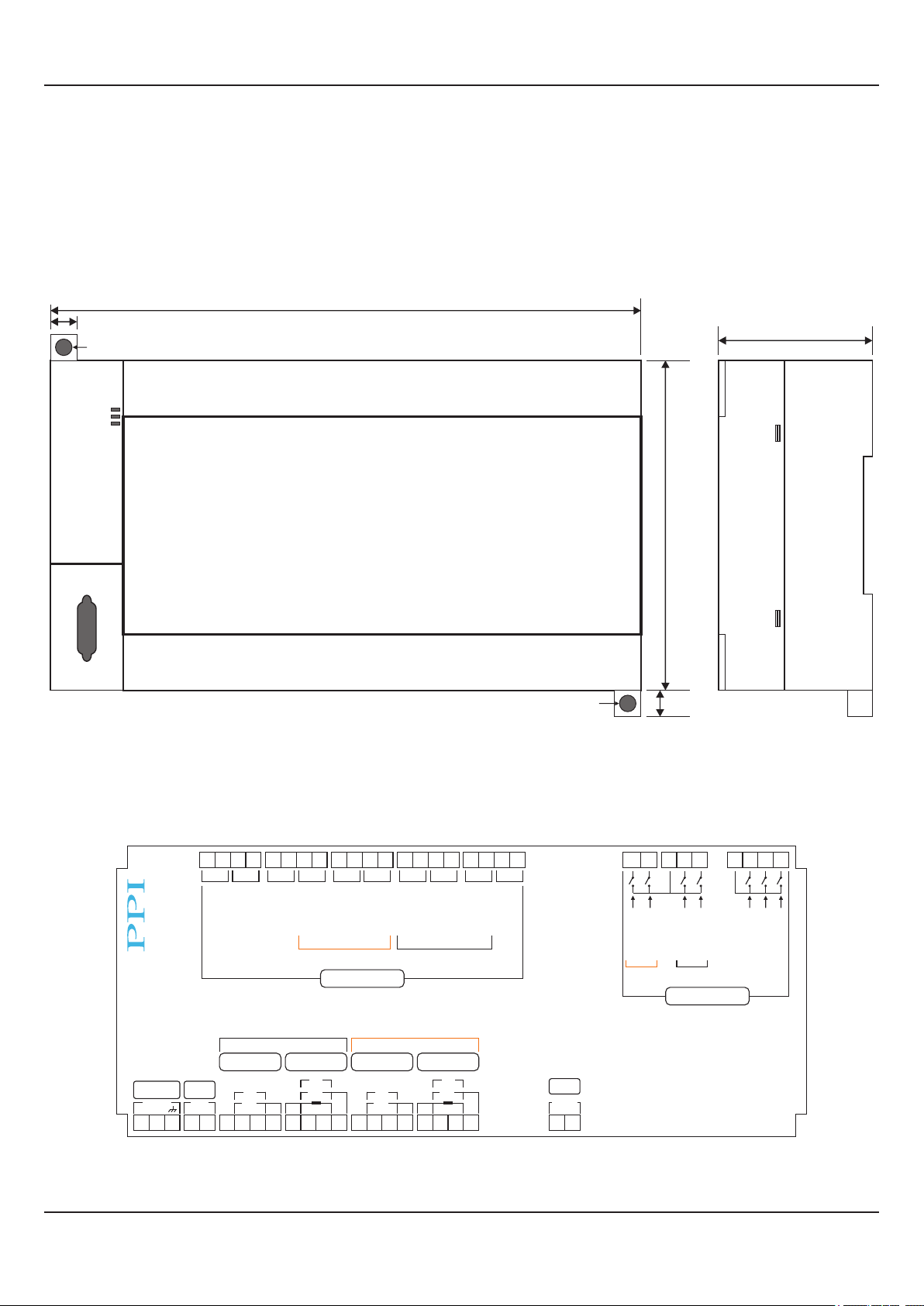
MOUNTING & ELECTRICAL CONNECTIONS : microPLC
Mounting (Base / Wall Mounting)
179mm
8mm
ø5mm Mounting Hole
Figure 2.1
77mm
100mm
microPLC Electrical Connections
27262524
+-+
Main Set Select
Main
Temperature
+
+
-
-
-
mA
Pt100
+-+
-
Door Lock
Stby Set Select
Humidity
Supply
-
5VDC
Exc
+
-
V
mA
-
-
18~32VDC
+
1 2 3 4 5 6 7 8 9 10 11 12 13 22 2314 15 16 17 18 19 20 21
-
Humidifier
Compressor
Standby
Digital Outputs
V
+
+
+
Humidity
-
Heater
-
V
mA
-
+
Standby
+
+
-
Compressor
Figure 2.2
-
+
-
+
Humidifier
Main
Temperature
V
+
-
+
-
mA
Pt100
ø5mm Mounting Hole
43424140393837363534333231302928
+
-
+
Alarm
Heater
HMI
RS485
-
+
Thermostat
Water Level
Stby
8mm
Thermostat
Water Level
Main
Digital Inputs
microPLC
Stability Control
Alarm ACK
525150494847464544
Power Fail
Door Open
4

HumiTherm Ultra User Manual
DESCRIPTIONS
The connections are described as under:
Main Humidity (%RH) Transmitter Input (Terminals : 7,8, 9)
The Controller accepts DC Current (mA) / DC Voltage (V) as Humidity input. The connections are
described below.
Humidity Transmitter with DC Voltage (V) Output
Figure 2.3 (a)
0/1~5V, 0~10V
7 8 9
V
The Figures 2.3(a) depicts wiring connections for voltage output transmitter. The Excitation Voltage
can be obtained from an external source or from the controller (5 VDC).
Humidity Transmitter with DC Current (mA) Output
The Figures 2.3(b) depict wiring connections for current output transmitter. Note that terminals 8 & 9
Figure 2.3 (b)
0/4~20mA
7
8 9
should be shorted. The Excitation Voltage can be obtained from an external source or from the
controller (5 VDC).
mA
Main Temperature (°C) Sensor / Transmitter Input (Terminals : 10, 11, 12, 13 )
The Controller accepts RTD Pt100 (3-wire / 2-wire) or DC Current (mA) / DC Voltage (V) as Temperature input. The
connections are described.
Figure 2.4 (a) Figure 2.4 (b) Figure 2.4 (c)
RTD Pt100
0/1~5V, 0~10V
0/4~20mA
10 11 12 13
10 11 12 13
V
10 11 12 13
mA
RTD Pt100, 3-wire
Connect single leaded end of RTD bulb to terminal 10 and the double leaded ends to terminals 11 & 12 as shown in Figure
2.4(a). Use copper conductor leads of very low resistance ensuring that all 3 leads are of the same gauge and length. Avoid
joints in the cable.
Temperature Transmitter with DC Voltage (V) Output
The Figures 2.4(b) depicts wiring connections for voltage output transmitter. The Excitation Voltage can be obtained from an
external source or from the controller (5 VDC).
Temperature Transmitter with DC Current (mA) Output
The Figures 2.4(c) depict wiring connections for current output transmitter. Note that terminals 12 & 13 should be shorted. The
Excitation Voltage can be obtained from an external source or from the controller (5 VDC).
5 VDC Excitation Voltage (Terminals : 4, 5)
The Controller is supplied with inbuilt 5VDC Excitation Voltage as standard. The Excitation Voltage can be used to power
external Temperature and/or RH Transmitters.
The ‘+’ and ‘-’ terminals are for voltage ‘Source’ and ‘Return’ paths, respectively.
5

HumiTherm Ultra User Manual
[Optional] Standby Humidity (%RH) Transmitter Input (Terminals : 14, 15, 16, 17)
[Optional] Standby Temperature (°C) Sensor / Transmitter Input (Terminals : 18, 19, 20, 21)
The Control Unit optionally supports Inputs for Standby (redundant) Humidity & Temperature sensor / transmitter. The
Connection detail are the same as for main sensor / transmitter described above.
[Optional] Door Output (terminals : 24, 25)
[Optional] Standby Set Select Output (terminals : 26, 27)
[Optional] Main Set Select Output (terminals : 28, 29)
[Optional] Standby Compressor Output (terminals : 30, 31)
[Optional] Standby Humidifier Output (terminals : 32, 33)
[Optional] Standby Heater Output (terminals : 34, 35)
Main Compressor Output (terminals : 36, 37)
Main Humidifier Output (terminals : 38, 39)
Main Heater Output (terminals : 40, 41)
Alarm Output (terminals : 42, 43)
All the above control & alarm outputs are Voltage pulses (12VDC @ 40mA) for driving external SSR or Relay. The ‘+’ and ‘-’
terminals are for voltage ‘Source’ and ‘Return’ paths, respectively.
The Optional Outputs are fitted only if Controller is ordered with Standby Control Outputs.
[Optional] Standby Thermostat Digital Input (Terminals 44, )46
[Optional] Standby Water Level Digital Input (Terminals 45, )46
Main Thermostat Digital Input (Terminals 47, )46
Main Water Level Digital Input (Terminals 48, )46
Alarm Acknowledge Digital Input (Terminals 50, )49
Power Fail Digital Input (Terminals 51, )49
Door Open Digital Input (Terminals 52, )49
(Terminals 46 & 49 are Common)
Potential-free contact closure input terminals are provided as digital inputs. An ‘Open’ or ‘Close’ switch position is detected as
input.
HMI (Terminals 22, 23) COMMUNICATION PORT
For reliable noise free communication, use a pair of twisted wires inside screened cable. The wire should have less than 100
ohms / km nominal DC resistance (Typically 24 AWG or thicker). Connect the terminating resistor (Typically 100 to 150 ohm)
at one end to improve noise immunity.
POWER SUPPLY 1(Terminals , 2, 3)
As standard, the is supplied with power connections suited Module
for to V C . The accuracy / p formance of the 18 32 D power source er
Module is not affected by the variations in the supply within sp cified e
limits of to 3 VDC. Use well-insulated copper conductor wire of 18 2
the size not smaller than 0.5mm² for power supply connections
ensuring proper polarity as shown in Figure . The is not 2.5 Module
provided with fuse and power switch. If necessary, mount them
DC Power
Source
+
-
Figure 2.5
Fuse
2 Pole
Isolating Switch
Mains
Earth
1
+
2
-
3
separately. Use a blow fuse rated for 0.5A current. slow
For safety and enhanced electrical noise immunity, it is highly recommended to connect Main Power Supply ‘Earth’
to terminal 3.
6

HumiTherm Ultra User Manual
Section 3
MOUNTING, ELECTRICAL CONNECTIONS & JUMPER SETTINGS : MAPPING
Mounting (Base / Wall Mounting)
Figure 3.1
210mm
205mm
ø5mm
Mounting Hole
5mm
8mm
ø5mm Mounting Hole
Mapping Electrical Connections
52 53
54
55
COMM PORT
B BB B
A1A2
28293031323334353637383940
B1B2
A3
°C
MAP 5
%RH
B3
A1A2
88mm
110mm
Figure 3.2
°C
A3
mA
mV / V
B1B2
MAP 8
B3
%RH
A1A2
B3
44
464748495051
45
%RH
4142
°C
RTD
A3
B1B2
43
MAP 7
mA
mV / V
%RH
B3
A1A2
B1B2
A3
°C
MAP 6
°C
PPI
MAP 1
°C
1 2
A1 A2 A3 B1 B2 B3
%RH
5
3
6 7 8 9 10
4
B1 B2 B3 A1 A2 A3 B1 B2 B3 A1 A2 A3 B1 B2 B3 A1 A2 A3
MAP 2
°C
A1 A2 A3
%RH
11 121314
MAP 3
°C
15 161718 19 20
%RH
%RH
B1 B2 B3
MAP 4
°C
21 222324
7
%RH
25
84 ~ 264
VAC
L
N
26 27
UniMap
SUPPLY
4 / 8 Points
Mapping Module
Sr. No.:

HumiTherm Ultra User Manual
Map Inputs
Each of the °C and %RH inputs are identical from wiring connection viewpoint. The descriptions below apply to all the inputs
with no deviations.
Make sure that proper jumper settings are made for each input for the selected input type as described later in this ection.s
Figure 3.3(b)Figure 3.3(a)
°C
RTD
A1 A2 A3
RTD Pt100, 3-wire
Connect single leaded end of bulb to and the double leaded ends to terminals and (interchangeable) as shown RTD A1 A2 A3
in Use copper conductor leads of very low resistance ensuring that all 3 leads are of the same gauge and length. Figure 3.3(a).
Avoid joints in the cable.
DC Linear Voltage (mV / V) & Current (mA)
Use a shielded twisted pair with the shield grounded at the signal source for connecting mA / mV / V source. Connect common
(-) to and the signal (+) to , as shown in A2 / B2 A1 / B1 Figure 3.3(a) & (b).
mV / V / mA
A1 A2
A3
%RH
mV / V / mA
B1 B2
B3
POWER SUPPLY
Figure 3.4
Fuse
2 Pole
Isolating Switch
Power Supply
Terminal
Line
26 (L)
Neutral
As standard, the controller is supplied with power connections suited for 8 to 264 VAC line supply. Use well-insulated copper 5
conductor wire of the size not smaller than 0.5mm² for power supply connections. Connect Line (Phase) supply line to terminal
26 and the Neutral (Return) supply line to terminal 27 as shown in Figure . . The controller is not provided with fuse and 3 4
power switch. If necessary, mount them separately. Use a time lag fuse rated 1A @ 240 VAC.
27 (N)
8

HumiTherm Ultra User Manual
SERIAL COMMUNICATION PORT
Figure 3.5
HMI
Port
RS485
Mapping
RS485 Port
IN
OUT
To microPLC
The wiring connections for interfacing the HMI with mapping unit is shown in the figure 3.5.
INPUT TYPE : JUMPER SETTINGS
The Mapping Unit (UniMap) is supplied with 8 ( ) or 16 ( T + 8RH) s. Each can be user configured for a 4T + 4RH 8 Map Input Input
variety of input types which requires appropriate parameters settings and jumper settings on . The figure shows UniMap 3.6
the locations of jumper setting arrangements for each . input
Figure 3.6
°C
MAP 1
1
2
4
3
°C
MAP 5
%RH
MAP 4
%RH
MAP 8
4
1
2
3
9

HumiTherm Ultra User Manual
The jumper setting arrangement comprises of as shown in the figure below. The figure also depicts Pins & Shorting-Link 3.7
how to mount the Shorting-Link for a particular jumper setting.
Figure 3.7
Pins
The figures below show the jumper settings for different input types.
Shorting
Link
Shorting Link
Placed
RTD Pt100 (3-wire)
3
2
1
Place Shorting
Link on Pins 1 & 2
4
0-50mV, 0-200mV, 0-1.25V,
0-5V, 1-5V, 0-10V
Shorting Link
Parked
0-20mA, 4-20mA
Place Shorting
Link on Pins 2 & 3
3
2
1
4
Park Shorting Link
10
3
2
1
4

HumiTherm Ultra User Manual
Section 4
BASIC OPERATION & PARAMETER ORGANIZATION
Upon Power up to the HMI, after a few initialization screens, the Main (Home) screen is displayed. This is the screen that shall
be used most often and is described below in details.
Battery Indicator
Comm Error Indicator
Calendar Date
Alarm Indicator
Clock Time
Temperature Value
Status View Button
Map View Button
Temperature Setpoint
(Optional Touch Button)
Tuning
Tune Status Indicator
%RH Value
%RH Setpoint
(Optional Touch Button)
Set-up Mode Button
Door Open Button
ALARM INDICATOR
This icon appears if one or more process alarms are active. The Alarm Relay gets activated whenever any alarm becomes
active. The user can acknowledge the alarm (de-activate the relay) by touching this icon.
BATTERY INDICATOR
This icon appears if the Mains power has failed and the controller is currently powered through an auxiliary power source like
Battery or Inverter.
COMM ERROR INDICATOR
This icon appears if the HMI communication link with the Control Unit, Mapping Unit or GSM Module is broken. Upon touching
this icon a message window pops up showing which communication link(s) is broken.
CALENDER DATE & CLOCK TIME
These two fields show the current date (DD/MM/YY) & time (HH:MM:SS, 24 Hours format), respectively.
TEMPERATURE VALUE & %RH VALUE
These two fields show the Temperature & %RH Process Values in 0.1 °C / %RH resolution. In case of errors the field shows
OPEN (Sensor Open), OVER (Process Value above Max Range), UNDR (Process Value below Min Range). The Process
Values are shown in Black color under normal condition. The Error Messages are shown in Red color.
TEMPERATURE SETPOINT & %RH SETPOINT
These two fields show the Temperature & %RH Set Values (SP) in 0.1 °C / %RH resolution. If enabled, these values can be
edited by touching the respective field. Upon touching a Numeric Keypad pops up for setting.
TUNE STATUS INDICATOR
This text appears if the controller is self tuning the temperature and / or %RH control loop.
STATUS VIEW BUTTON
This a touch button that enables navigation through various process status screens. The Screens are shown below.
11

HumiTherm Ultra User Manual
Process Status Screen
This screen shows various rocess Alarm status and the information regarding working / fa ure of p il various Main and Standby
Sensors (Temperature & %RH) & Control Gadgets (Air Heater, Boiler Heater & Compressor). The contents on this screen are
dependent on whether Standby Sensors and / or Standby Control Gadgets are installed or not. Accordingly the following four
variants of this screen exist:
1. Alarm Only
2. Alarm + Standby Sensor
3. Alarm + Standby Control
4. Alarm + Standby Sensor + Standby Control
Alarm Only
Touch Button to go to
Home (Main) Screen
Touch Button to go to
Next Screen
Touch Button to
Acknowledge Alarm
Alarm + Standby Control
Touch Button to go to
Previous Screen
Alarm + Standby Sensor
Alarm + Standby Sensor + Standby Control
12

HumiTherm Ultra User Manual
Output Status
This screen shows :
w Heating & Humidification % output power
w On-Off Status for Main & Standby (if installed) Air Heater, Boiler Heater (Humidifier) & Compressor
w Alarm Relay Status
Record Status
Th rage capacity, numbers of current stored records and available free space.is screen shows the total record sto
SMS Status
This screen shows the status related to GSM Module (if installed).
5000
1
4999
13

HumiTherm Ultra User Manual
MAP VIEW BUTTON
This is a touch button that opens up screen(s) to view process values for mapping s. The installed mapping s could input input
be 8 (4 Map Points : 4T + 4RH) or 16 (8 8T + 8RH) and accordingly 1 or 2 screens displayed. Note that this Map Points : are
touch button is not available if no mapping inputs are installed. The Screens are shown below.
Appears for both 8 & 16 Map Inputs
22.0
57.5
25.1
60.8
DOOR OPEN BUTTON
If the Humidity cabinet is equipped with Door Lock, this touch button opens a screen that allows password entry for unlocking
the cabinet door by authorised person. Also the authorised person’s identity is logged for audit purpose.
24.8
61.2
27.2
62.3
Appears for 16 Map Inputs only
25.0
59.6
25.2
60.8
24.7
60.2
25.3
60.1
SET-UP MODE BUTTON
This touch button opens a screen that allows access to Operator, Supervisory or Factory Level parameter settings through
appropriate password entry. 4 character
The Factory default passwords are as below :
Access Level
Operator
Supervisory
Factory
Default Password
0000
0001
0002
14

HumiTherm Ultra User Manual
Upon touching one of the levels, a keyboard for password entry pops-up as shown below.
The user must touch the text screen to make it
editable. Upon touch the text screen shows a blue
band as shown below.
Text Screen
****
Non Editable
Editable after touch
****
Password entry on
editable text Screen
While the screen is editable, type 4 character password & then press ENTER Key. If the password is correct, the parameter
setting screen opens up. Use ESC key (in case password is not known) to pop down the key pad.
Once an access level is entered, the user can change the password for that level as shown below as an example for operator
level.
25.0
2.0
2.0
60.0
2.0
2.0
0005
15

HumiTherm Ultra User Manual
Each access level may have sub levels for convenient parameter grouping. The Table . lists various parameters with levels 4 1
and sub levels.
Table 4.1
Level
Operator
Supervisory
Recording
Clock & Calendar
SMS
SMS Alert
Door Lock Access
Standby Switching
Sub-Level
Parameters
Temperature
Set Value
Low Deviation Alarm
High Deviation Alarm
%RH
Set Value
Low Deviation Alarm
High Deviation Alarm
SP Edit on Home Screen
Recording Interval
‘Delete Record’ Command
Calendar Date (DD/MM/YY)
Clock Time (HH:MM:SS)
GSM Machine ID
Reset GSM Module
Lock Position (On / Off)
Password Entry
‘Switch Main / Standby Outputs’
‘Switch to Standby Sensors’
Factory
Maintenance
Temperature
%RH
Input Settings
Alarm Settings
Control Settings
Input Settings
Alarm Settings
Control Settings
Repair Acknowledge ‘Control Gadget’
Repair Acknowledge ‘Input Sensor’
Input Type,
Signal Range Low, Signal Range High,
Display Range Low, Display Range High,
Zero Offset
Inhibit (Yes / No),
Low Alarm Deviation, High Alarm Deviation,
Hysteresis
Heat Zone PID Constants,
Cool Zone PID Constants,
Output Cycle Time (Sec.),
Control SP
Setpoint Low Limit, Setpoint High Limit
Self Tune
16

HumiTherm Ultra User Manual
Level
Factory
Compressor
Water Level
Door Open
Power Fail
Standby
Sub-Level
Sensor Inputs
Control Gadgets
Parameters
Mode (ON, OFF, PV Based, SP Based),
Boundary SP or Compressor SP,
Time Delay, Hysteresis
Zone Select (Single, Dual)
Float
Detection Enable (Yes / No),
Low Level Logic (Open / Close)
Thermostat
Detection Enable (Yes / No),
Low Level Logic (Open / Close)
Common Boiler (Yes / No)
Detection Enable (Yes / No),
Door Open Logic (Open / Close),
Alarm Delay (Sec.)
Detection Enable (Yes / No),
Power Fail Logic (Open / Close)
Sensor Fail Detection Limits
Fail Detect Time (Min)
Cyclic Time (Hrs.)
Inhibit Time (Hrs.)
Mapping
Configuration
Temperature
%RH
Alarm Settings
Input Settings
Alarm Settings
Input Settings
Select Mapping Inputs (4T + 4RH, 8T + 8RH)
Low Alarm (Common for all Inputs)
Set Value, Hysteresis, Inhibit
High Alarm (Common for all Inputs)
Set Value, Hysteresis, Inhibit
Input Type,
Range Low, Range High,
Zero Offset
Low Alarm (Common for all Inputs)
Set Value, Hysteresis, Inhibit
High Alarm (Common for all Inputs)
Set Value, Hysteresis, Inhibit
Input Type,
Range Low, Range High,
Zero Offset
17

HumiTherm Ultra User Manual
PARAMETER SETTINGS
There are 3 types of parameters; Numeric, String Option and Commands. The setting methods for different types are
described below.
Numeric Parameters
This type of parameter has 2 fields; & as shown in the figure. The value for this type of parameter is set Name Field Value Field
using a Numeric keypad that pops up upon touching the for the parameter. The value can be edited using numeric Value Field
keys & other functional keys as shown in the figure. Use ENT key for storing the new value or use ESC key to revert without
changes. Touching ENT or ESC key, the keypad automatically collapses.
Note that if the modified value falls outside the Minimum or Maximum limits specified for the
parameter value then the parameter retains the old value.
Name Field Value Field
String Option Parameters
This type of parameter has 2 or more fixed options to choose from. All the options are shown in rectangular boxes with
appropriate texts as shown in the figure. Only one of the several options can be selected. The selected option box is shown in
bright ( ) color, while all other unselected options are shown in dark ( ) color. For selecting the desired option. just touch
the box and wait for a while until the color changes from unselected to selected.
Selected Option
Unselected Options
18

HumiTherm Ultra User Manual
Command Parameters
This type of parameter is used to perform specific actions like Start / Abort tuning, Delete Records, etc. A touch Push Button
image is provided for issuance of command as shown in the figure. Usually an acknowledgment window with OK button pops
up to indicate the action performed. The window collapses upon touching the OK button.
ALARM MESSAGE WINDOWS
For the Alarms related to gadget or sensor failure, door open detection, low water level detection, etc.; message windows are
popped up on the Main (Home) Screen showing the cause of alarm and action taken by the controller. The figure below shows,
for example, the message screen that pops up when the controller detects Main Sensor Set Failure & changes over to the
Standby Set.
19

HumiTherm Ultra User Manual
Section 5
OPERATOR LEVEL PARAMETERS
Operator
25.0
2.0
2.0
Temperature Set Value
Range : Temperature Setpoint ow imit to Temperature Setpoint High LimitL L
Default : 25.0 °C
This is the Setpoint Value for temperature control loop. This value can also be set on home screen if enabled through the
parameter SP Edit on Home Screen.
Temperature Low Deviation Alarm
Range : 0.2 to 99.9 °C
Default : 2.0 °C
This Parameter sets a Negative Deviation (offset) limit with respect to the ‘ ’. The Alarm is activated if the Temperature Set Value
measured temperature value falls below this limit.
60.0
2.0
2.0
Temperature High Deviation Alarm
Range : 0.2 to 99.9 °C
Default : 2.0 °C
This Parameter sets a Positive Deviation (offset) limit with respect to the ‘ ’. The Alarm is activated if the Temperature Set Value
measured temperature value exceeds this limit.
%RH Set Value
Range : %RH Setpoint Low Limit to %RH Setpoint High Limit
Default : 60.0 %
This is the Setpoint Value for %RH control loop. This value can also be set on home screen if enabled through the parameter
SP Edit on Home Page.
%RH Low Deviation Alarm
Range : 0.2 to 99.9 %
Default : 2.0 %
This Parameter sets a Negative Deviation (offset) limit with respect to the ‘ ’. The Alarm is activated if the %RH Set Value
measured %RH value falls below this limit.
20

HumiTherm Ultra User Manual
%RH High Deviation Alarm
Range : 0.2 to 99.9 %
Default : 2.0 %
This Parameter sets a Positive Deviation (offset) limit with respect to the ‘ ’. The Alarm is activated if the %RH Set Value
measured %RH value exceeds this limit.
SP Edit on Home Screen
This parameter allows to Enable or Disable the set editing for both temperature & %RH on Home (Main) Screen. If value
Enabled, the temperature & %RH set values can be edited by touching the receptive indicated values on the ome creen.H S
21

HumiTherm Ultra User Manual
Section 6
SUPERVISORY LEVEL PARAMETERS
Supervisory Recording
Recording Interval
Range : 1 to 250 Minutes
Default : 5 Minutes
The Controller generates and stores periodic records at the interval set by this parameter.
‘Delete Record’ Command
This command is issued using the touch push button. All the stored records are deleted from the memory.
Supervisory
Clock & Calendar
16
12
2016
212112
Operate this touch button
to register new Date / Time
Calendar Date
Clock Time
The Calendar Date is set using 3 separate fields; Date (DD), Month (MM) & Year (YY).
The Clock Time is set in 24 Hours format using 3 separate fields; Hours (HH), Minutes (MM) & Seconds (SS).
It is a must to operate the ‘Apply’ touch button in order to register the modified values.
22

HumiTherm Ultra User Manual
Supervisory
SMS
SMS Alert
(Available only if the controller is supplied with GSM Module Version)
GSM Machine ID
Range : 1 to 128
Default : 1
This parameter can be used to assigned a unique ID to the machine (chamber) to identify the source of SMS alert.
‘Reset GSM Module’
Use this touch button if for any reason the GSM module fails to send SMS alerts.
Supervisory
Door Lock Access
USER1234
USER1234
ABCDEFGH
12345678
Valid Password entries
Unused IDs
Key for registering
New Password entry
Key for Deleting an
existing Password entry
23

HumiTherm Ultra User Manual
Lock Position
Options : Solenoid O , Solenoid ON FF
Default : Solenoid OFF
Set this parameter to ‘Solenoid ON’, if the chamber door is locked when the solenoid is turned ON (energized). Set this
parameter to ‘Solenoid OFF’, if the chamber door is locked when the solenoid is turned OFF (de-energized).
Password Entry
The Supervisor can Authorize up to 7 Persons by assigning them their respective . A 8 Character Alpha-Numeric Password
table with 2 columns (ID & PASSWORD) is provided for password entries. The ID numbers are fixed from 1 to 7 and
correspond to the made in the PC Software (HumiLog). The Password against each ID can be entered / edited / Name Entries
deleted by touching the table cell provided for the ID. Upon touching the cell, an alpha numeric keypad pops up. Use alpha
numeric keys to assign a new password (or edit the existing password) and then press ENTER key. To delete an exiting
password use CLR key and then press ENTER key. The passwords can be entered / deleted in any order of ID. The password
fields for unused Ids must be cleared (empty).
Supervisory
Standby Switchings
Switch Main / Standby Outputs
If the controller is installed with standby control gadget set, the user can manually switch between the Main and the Standby
set by using the touch push button. The switching is permitted / performed only if both sets are working.
Switch to Standby Sensors
If the controller is installed with Standby Sensor set, the user can manual switch to the Standby set if he detects failure of either
temperature or RH sensor from Main set. The switching is permitted / performed only if the Standby Sensor set is working.
24

HumiTherm Ultra User Manual
Supervisory
Maintenance
Repair Acknowledge
In case the control system is installed with standby set of sensors and / or control gadgets, the controller automatically
switches to the Standby set should any of the sensors / control gadgets of the Main set fail. After fixing the fault / failure, the
user must acknowledge the same to the controller for resuming the operation with the main set. The following touch buttons
are provided for the purpose depending on the standby installation.
25

HumiTherm Ultra User Manual
Section 7
FACTORY LEVEL PARAMETERS
Temperature
Input Type
Options RTD Pt100, 0 to 20 mA, 4 to 20 mA, 0 to 5 V, 0 to 10 V, 1 to 5 V :
Default : RTD Pt100
Select Input type in accordance with the type of Temperature sensor / transmitter connected for measurement.
Signal Range Low
(Available for DC Linear Volts & mA Inputs only)
Input SettingsFactory
Input Type
0 to 20 mA
4 to 20 mA
0 to 5 V
0 to 10 V
1 to 5 V
This parameter is the transmitter output signal value that corresponds to the Range Low process value. Refer Appendix-A :
DC Linear Signal Interface for details.
Signal Range High
(Available for DC Linear Volts & mA Inputs only)
Input Type
0 to 20 mA
4 to 20 mA
0 to 5 V
0 to 10 V
1 to 5 V
Settings
0.00 to Signal High
4.00 to Signal High
0.000 to Signal High
0.00 to Signal High
1.000 to Signal High
Settings
Signal Low to 20.00
Signal Low to 20.00
Signal Low to 5.000
Signal Low to 10.00
Signal Low to 5.000
Default
0.00
4.00
0.000
0.00
1.000
Default
20.00
20.00
5.000
10.00
5.000
This parameter is the transmitter output signal value that corresponds to the Range High process value. Refer Appendix-A :
DC Linear Signal Interface for details.
26

HumiTherm Ultra User Manual
Display Range Low
(Available for DC Linear Volts & mA Inputs only)
Range : -199.9 to Range High
Default : 0.0
This parameter is the rocess alue that correspond to the Signal Low value fromP V s the transmitter. Refer Appendix-A : DC
Linear Signal Interface for details.
Display Range High
(Available for DC Linear Volts & mA Inputs only)
Range : Range Low to 999.9
Default : 100.0
Th Process alue that correspond to the Signal High value from the transmitter. is parameter is the V s Refer Appendix-A : DC
Linear Signal Interface for details.
Zero offset
Range : -50.0 to 50.0 °C
Default : 0.0 °C
This value is algebraically added to the measured Temperature Value to derive the final Value that is displayed and compared
for alarm / control. Use this value to nullify any known constant error.
Final Value = Measured Value + Offset
Factory
Temperature
Alarm Settings
5.0
5.0
2.0
Inhibit
Options Enable, Disable :
Default : Enable
If this parameter is set to ‘ ’, the Alarm activation is suppressed until the Temperature value is within Alarm limits from the Enable
time the controller is switched ON. This allows suppressing the Alarm during the start-up Alarm conditions.
If this parameter is set to ‘Disable’, the Alarm is not suppressed during the start-up Alarm conditions.
27

HumiTherm Ultra User Manual
Low Alarm Deviation
Range : 0.2 to 99.9 °C
Default : 2.0 °C
This parameter sets the maximum permissible process value deviation the temperature setpoint. If the temperature below
exceeds this deviation, the alarm is activated.
High Alarm Deviation
Range : 0.2 to 99.9 °C
Default : 2.0 °C
This parameter sets the maximum permissible process value deviation the temperature setpoint. If the temperature above
exceeds this deviation, the alarm is activated.
Hysteresis
Range : 0.1 to 99.9
Default : 0.2
This parameter sets a differential (dead) band between the ON and OFF emperature Deviation Alarm status change. Keep it T
large enough to avoid frequent switching of the Alarm Status/Relay.
Factory
Temperature
50.0
Control Settings
50.0
25.0
100
100
0.0
16
16
100.0
10.0
The control settings for temperature comprises of two screens shown above. Also the first screen parameters change
depending on the selection for the parameter ‘Zone elect’ (Single or Dual) provided on the screen “Compressor SS ettings”.
The Cool Zone and Heat Appendix-B : Compressor Switching StrategiesZone are described in details in . The screen for
parameters for Dual Zone is shown above and that for Single Zone is shown below.
28
50.0
100
16
10.0

HumiTherm Ultra User Manual
The PID Constants are described below.Dual Zone
Heat Zone Proportional Band
Range : 0.1 to 999.9 °C
Default : 50.0 °C
Sets proportional gain for Heat Pre-dominant zone.
Heat Zone Integral Time
Range : 0 to 3600 Sec.
Default : 100 Sec.
Sets integral time constant in Seconds for Heat Pre-dominant zone. Setting the value to 0, cuts-off integral action.
Heat Zone Derivative Time
Range : 0 to 600 Sec.
Default : 16 Sec.
Sets derivative time constant in Seconds for Heat Pre-dominant zone. Setting the value to 0, cuts-off derivative action.
Cool Zone Proportional Band
Range : 0.1 to 999.9 °C
Default : 50.0 °C
Sets proportional gain for Cool Pre-dominant zone.
Cool Zone Integral Time
Range : 0 to 3600 Sec.
Default : 100 Sec.
Sets integral time constant in Seconds for Cool Pre-dominant zone. Setting the value to 0, cuts-off integral action.
Cool Zone Derivative Time
Range : 0 to 600 Sec.
Default : 16 Sec.
Sets derivative time constant in Seconds for Cool Pre-dominant zone. Setting the value to 0, cuts-off derivative action.
The PID Constants are described below.Single Zone
Proportional Band
Range : 0.1 to 999.9 °C
Default : 50.0 °C
Sets proportional gain.
Integral Time
Range : 0 to 3600 Sec.
Default : 100 Sec.
Sets integral time constant in Seconds. Setting the value to 0, cuts-off integral action.
29

HumiTherm Ultra User Manual
Derivative Time
Range : 0 to 600 Sec.
Default : 16 Sec.
Sets derivative time constant in Seconds. Setting the value to 0, cuts-off derivative action.
The parameters below are applicable to both & .Single Zone Dual Zone
Output Cycle Time (Sec.)
Range : 0.5 to 100.0 Sec.
Default : 10.0 Sec.
Sets the total ‘On + Off’ time in seconds for time proportional power output for Air Heater through Relay / SSR.
Set Value (Temperature Control Loop)
Range : Temperature Setpoint Low Limit to Temperature Setpoint High Limit
Default : 25.0
Sets Value for Temperature Control.
Low Limit (for Temperature Control Set Value)
Range : -199.9 to Temperature Setpoint High Limit
Default : 10.0
Minimum permissible setpoint value for Temperature control.
High Limit (for Temperature Control Set Value)
Range : For RTD : Temperature Setpoint Low Limit to 600.0
For mA/V : Temperature Setpoint Low Limit to 999.9
Default : 60.0
Maximum permissible setpoint value for Temperature control.
Self Tune
This parameter is a command to Start or Abort Self Tuning for automatic computation of PID constants. The command starts or
aborts self tuning for both temperature & %RH simultaneously. For Dual Zone setting, the controller needs to be tuned
separately for Heat prominent & Cool Prominent zones.
Pressing the touch push button initiates tuning if the controller is already not tuning. However, if the controller is tuning,
pressing the touch button causes the controller to abort tuning.
30

HumiTherm Ultra User Manual
%RH
Input Type
Options 0 to 20 mA, 4 to 20 mA, 0 to 5 V, 0 to 10 V, 1 to 5 V :
Default : 0 to 5 V
Select Input type in accordance with the type of sensor / transmitter connected for measurement.%RH
Signal Range Low
Input SettingsFactory
Input Type
0 to 20 mA
4 to 20 mA
0 to 5 V
0 to 10 V
1 to 5 V
This parameter is the transmitter output signal value that corresponds to the Range Low process value. Refer Appendix-A :
DC Linear Signal Interface for details.
Signal Range High
Input Type
0 to 20 mA
4 to 20 mA
0 to 5 V
0 to 10 V
1 to 5 V
This parameter is the transmitter output signal value that corresponds to the Range High process value. Refer Appendix-A :
DC Linear Signal Interface for details.
Settings
0.00 to Signal High
4.00 to Signal High
0.000 to Signal High
0.00 to Signal High
1.000 to Signal High
Settings
Signal Low to 20.00
Signal Low to 20.00
Signal Low to 5.000
Signal Low to 10.00
Signal Low to 5.000
Default
0.00
4.00
0.000
0.00
1.000
Default
20.00
20.00
5.000
10.00
5.000
31

HumiTherm Ultra User Manual
Display Range Low
Range : -199.9 to Range High
Default : 0.0
This parameter is the rocess alue that correspond to the Signal Low value fromP V s the transmitter. Refer Appendix-A : DC
Linear Signal Interface for details.
Display Range High
Range : Range Low to 999.9
Default : 100.0
Th Process alue that correspond to the Signal High value from the transmitter. is parameter is the V s Refer Appendix-A : DC
Linear Signal Interface for details.
Zero offset
Range : -50.0 to 50.0 %
Default : 0.0 %
This value is algebraically added to the measured Value to derive the final Value that is displayed and compared for %RH
alarm / control. Use this value to nullify any known constant error.
Final Value = Measured Value + Offset
Factory Alarm Settings
%RH
5.0
5.0
2.0
Inhibit
Options Enable, Disable :
Default : Enable
If this parameter is set to ‘ ’, the Alarm activation is suppressed until the value is within Alarm limits from the time Enable %RH
the controller is switched ON. This allows suppressing the Alarm during the start-up Alarm conditions.
If this parameter is set to ‘Disable’, the Alarm is not suppressed during the start-up Alarm conditions.
Low Alarm Deviation
Range : 0.2 to 99.9 %
Default : 2.0 %
This parameter sets the maximum permissible process value deviation the setpoint. If the exceeds this below %RH %RH
deviation, the alarm is activated.
32

HumiTherm Ultra User Manual
High Alarm Deviation
Range : 0.2 to 99.9 %
Default : 2.0 %
This parameter sets the maximum permissible process value deviation the setpoint. If the exceeds this above %RH %RH
deviation, the alarm is activated.
Hysteresis
Range : 0.1 to 99.9
Default : 0.2
This parameter sets a differential (dead) band between the ON and OFF Deviation Alarm status change. Keep it large %RH
enough to avoid frequent switching of the Alarm Status/Relay.
Factory Control Settings
%RH
50.0
50.0
25.0
100
100
0.0
16
16
100.0
10.0
The control settings for comprises of two screens shown above. Also the first screen parameters change depending on %RH
the selection for the parameter ‘Zone elect’ (Single or Dual) provided on the screen “Compressor SS ettings”. The Cool Zone
and Heat Appendix-B : Compressor Switching StrategiesZone are described in details in . The screen for parameters for
Dual Zone is shown above and that for Single Zone is shown below.
33
50.0
100
16
10.0

HumiTherm Ultra User Manual
The PID Constants are described below.Dual Zone
Heat Zone Proportional Band
Range : 0.1 to 999.9 %RH
Default : 50.0 %RH
Sets proportional gain for Heat Pre-dominant zone.
Heat Zone Integral Time
Range : 0 to 3600 Sec.
Default : 100 Sec.
Sets integral time constant in Seconds for Heat Pre-dominant zone. Setting the value to 0, cuts-off integral action.
Heat Zone Derivative Time
Range : 0 to 600 Sec.
Default : 16 Sec.
Sets derivative time constant in Seconds for Heat Pre-dominant zone. Setting the value to 0, cuts-off derivative action.
Cool Zone Proportional Band
Range : 0.1 to 999.9 %RH
Default : 50.0 %RH
Sets proportional gain for Cool Pre-dominant zone.
Cool Zone Integral Time
Range : 0 to 3600 Sec.
Default : 100 Sec.
Sets integral time constant in Seconds for Cool Pre-dominant zone. Setting the value to 0, cuts-off integral action.
Cool Zone Derivative Time
Range : 0 to 600 Sec.
Default : 16 Sec.
Sets derivative time constant in Seconds for Cool Pre-dominant zone. Setting the value to 0, cuts-off derivative action.
The PID Constants are described below.Single Zone
Proportional Band
Range : 0.1 to 999.9 %RH
Default : 50.0 %RH
Sets proportional gain.
Integral Time
Range : 0 to 3600 Sec.
Default : 100 Sec.
Sets integral time constant in Seconds. Setting the value to 0, cuts-off integral action.
34

HumiTherm Ultra User Manual
Derivative Time
Range : 0 to 600 Sec.
Default : 16 Sec.
Sets derivative time constant in Seconds. Setting the value to 0, cuts-off derivative action.
The parameters below are applicable to both & .Single Zone Dual Zone
Output Cycle Time (Sec.)
Range : 0.5 to 100.0 Sec.
Default : 10.0 Sec.
Sets the total ‘On + Off’ time in seconds for time proportional power output for Air Heater through Relay / SSR.
Set Value ( Control Loop)%RH
Range : Setpoint Low Limit to Setpoint High Limit%RH %RH
Default : 25.0
Sets Value for Control.%RH
Low Limit (for %RH Control Set Value)
Range : . to Setpoint High Limit0 0 %RH
Default : 0.0
Minimum permissible setpoint value for control.%RH
High Limit (for %RH Control Set Value)
Range : %RH Setpoint Low Limit to 100.0
Default : 0.010
Maximum permissible setpoint value for control.%RH
Self Tune
This parameter is a command to Start or Abort Self Tuning for automatic computation of PID constants. The command starts or
aborts self tuning for both %RH & temperature simultaneously. For Dual Zone setting, the controller needs to be tuned
separately for Heat prominent & Cool Prominent zones.
Pressing the touch push button initiates tuning if the controller is already not tuning. However, if the controller is tuning,
pressing the touch button causes the controller to abort tuning.
35

HumiTherm Ultra User Manual
Factory
Compressor
For detailed description and functioning of the parameters related to compressor operation, refer
Appendix-B : Compressor Switching Strategies.
Mode
Options FF N : Continuous O , Continuous O , SP Based ON-OFF, PV Based ON-OFF
Default : Continuous OFF
Compressor SP
Range : 0.0 to 100.0
Default : .045
Boundary SP
Range : 0.0 to 100.0
Default : .0 45
Time Delay
Range : 0 to 1000 Sec.
Default : 200 Sec.
Hysteresis
Range : 0.1 to 99.9 °C
Default : 2.0 °C
Zone Select
Options : Single, Dual
Default : Single
36

HumiTherm Ultra User Manual
Factory
Water Level
Float Detection Enable
Options No, Yes :
Default : No
Set to ‘Yes’ if Float Switch is mounted for detecting Low water level.
Float Low Level Logic
Options : Switch Open, Switch Close
Default : Switch Close
If set to ‘Switch Close’, the water level is considered Low if the switch is CLOSE. If set to ‘Switch Open’, the water level is
considered Low if the switch is OPEN.
Thermostat Detection Enable
Options No, Yes :
Default : No
Set to ‘Yes’ if Thermostat is mounted for detecting Low water level.
Thermostat Low Level Logic
Options : Switch Open, Switch Close
Default : Switch Close
If set to ‘Switch Close’, the water level is considered Low if the thermostat contacts are CLOSE. If set to ‘Switch Open’, the
water level is considered Low if the thermostat contacts are OPEN.
Common Boiler
Options : No, Yes
Default : No
This parameter is shown on the screen only if Standby Control Gadget option is enabled / installed. Set this parameter to ‘Yes’
if both, Main and Standby, heaters are mounted in a single steam generating boiler. In this case, only a single pair of Float
Switch & Thermostat is used and connected to Main Digital Inputs.
37

HumiTherm Ultra User Manual
Factory
Door Open
Detection Enable
Options No, Yes :
Default : No
Set to ‘Yes’ if Door Open detection switch is mounted.
Door Open Logic
Options : Switch Open, Switch Close
Default : Switch Close
If this parameter is set to ‘Switch Close’, the door is detected as if the switch is CLOSE. If this parameter is set to ‘Switch Open
Open’, the door is detected as if the switch is OPEN.Open
Alarm Delay (Sec.)
Range : 0 to 1000 Sec.
Default : 60 Sec.
This parameter sets a timer. From the time the door is opened, the timer begins counting down. If the door is not closed before
the timer reaches 0, the alarm is activated.Door Open
Factory
Power Fail
38

HumiTherm Ultra User Manual
Detection Enable
Options No, Yes :
Default : No
Set to ‘Yes’ if provision is made for running the controller on an auxiliary power sources like battery or inverter and a Switch is
mounted for detecting main power source failure.
Power Fail Logic
Options : Switch Open, Switch Close
Default : Switch Close
If set to ‘Switch Close’, the CLOSE witch position indicates that the Mains Power has failed and the Controller is operating on s
auxiliary power source. If set to ‘Switch Open’, the OPEN switch position indicates that the Mains Power has failed and the
Controller is operating on auxiliary power source.
Factory Standby
Sensor Inputs
These parameters are particularly useful when sensors with DC Volts / Current Outputs are used for measuring temperature
and / or %RH.
Temperature Low Limit for Sensor Fail Detection
Range : 0 to 25.0 °C
Default : 0 °C
This parameter should be set to a value below which the temperature is not likely to fail under normal conditions. In case of
sensor open / fail, the output signal will generally fall to minimum level corresponding to Low Process Value. This condition is
detected as sensor fail & the controller switches to alternate set of sensors.
%RH Low Limit for Sensor Fail Detection
Range : 0 to 60.0 %
Default : 0 %
Description is same as for “Temperature Low Limit for Sensor Fail Detection”.
39

HumiTherm Ultra User Manual
Factory
Standby Control Gadgets
Fail Detect Time (Min)
Range : 0 to 250 Min.
Default : 10 Min
This parameter sets a timer. If either temperature or %RH process value exceeds “High Alarm Deviation” limit, the timer starts
counting down. If the process value does not return below the “High Alarm Deviation” limit before the timer reaches 0, the
working control gadget set is detected as failed. The controller then switches to the alternate control gadget set.
Cyclic Time (Hrs.)
Range : 0 to 500 Hrs.
Default : 48 Hrs.
If both, Main & Standby, control gadget sets are in working condition, the controller keeps switching between these two sets
periodically with a time interval set by this parameter value.
Inhibit Time (Hrs.)
Range : 0 to 250 Hrs.
Default : 1 Hrs.
This parameter sets a time interval for which the controller stops monitoring the control gadget fail detection condition
(described under parameter “Fail Detect Time”). This time interval is usually applied under following conditions.
1. System is powered (Start Up)
2. Change-over from Auxiliary Power source (Battery / Inverter) to Mains Power
3. After recovery from Door Open Alarm
4. Change-over from Main to Standby Control gadget Set or vice-a-versa
This feature suppresses false detection of control gadget failure.
40

HumiTherm Ultra User Manual
Factory
Mapping Configuration
Select Mapping Inputs
Options : 4T + 4RH, 8T + 8RH
Default : 4T + 4RH
Select this parameter depending upon whether 8 input (4 Temperature + 4 %RH) or 16 input (8 Temperature + 8 %RH) unit is
installed for mapping.
Factory Mapping
Temperature
Alarm Settings
Low Alarm Set Value
Range : -199.9 to 600.0 °C
Default : 0 °C
This parameter sets a Temperature value limit which an alarm is generated. common below
Low Alarm Hysteresis
Range : 0.1 to 50.0 °C
Default : 2.0 °C
This parameter sets a differential (dead) band between the ON and OFF Low Temperature Alarm status change. Keep it large
enough to avoid frequent switching of the Alarm Status/Relay.
Low Alarm Inhibit
Options : Enable, Disable
Default : Disable
If this parameter is set to ‘Enable’, the Alarm activation is suppressed until the Temperature value is above the Low Alarm Set
Value from the time the controller is switched ON. This allows suppressing the Alarm during the start-up Alarm conditions.
41

HumiTherm Ultra User Manual
If this parameter is set to ‘Disable’, the Alarm is not suppressed during the start-up Alarm conditions.
High Alarm Set Value
Range : -199.9 to 600.0 °C
Default : 0 °C
This parameter sets a Temperature value limit which an alarm is generated. common above
High Alarm Hysteresis
Range : 0.1 to 50.0 °C
Default : 2.0 °C
This parameter sets a differential (dead) band between the ON and OFF High Temperature Alarm status change. Keep it large
enough to avoid frequent switching of the Alarm Status/Relay.
High Alarm Inhibit
Options : Enable, Disable
Default : Disable
If this parameter is set to ‘Enable’, the Alarm activation is suppressed until the Temperature value is below the High Alarm Set
Value from the time the controller is switched ON. This allows suppressing the Alarm during the start-up Alarm conditions.
If this parameter is set to ‘Disable’, the Alarm is not suppressed during the start-up Alarm conditions.
Factory Mapping
Temperature
0.0
100.0
Input Settings
All the arameter settings, except Zero Offset, on this screen are Common for all p
Temperature Inputs.
Input Type
Options RTD Pt100, 0 to 20 mA, 4 to 20 mA, 0 to 50 mV, 0 to 200 mV, 0 to 1.25 V, 0 to 5 V, : 1 to 5 V, 0 to 10 V
Default : RTD Pt100
Select Input type in accordance with the type of Temperature sensor / transmitter connected for measurement.
Signal Range Low
(Available for DC Linear Volts & mA Inputs only)
42

HumiTherm Ultra User Manual
Input Type
0 to 20 mA
4 to 20 mA
0 to 50 mV
0 to 200 mV
0 to 1.25 V
0 to 5 V
1 to 5 V
0 to 10 V
This parameter is the transmitter output signal value that corresponds to the Range Low process value. Refer Appendix-A :
DC Linear Signal Interface for details.
Signal Range High
(Available for DC Linear Volts & mA Inputs only)
Input Type
0 to 20 mA
4 to 20 mA
0 to 50 mV
0 to 200 mV
0 to 1.25 V
0 to 5 V
1 to 5 V
0 to 10 V
Settings
0.00 to Signal High
4.00 to Signal High
0.00 to Signal High
0.0 to Signal High
0.000 to Signal High
0.000 to Signal High
1.000 to Signal High
0.00 to Signal High
Settings
Signal Low to 20.00
Signal Low to 20.00
Signal Low to 50.00
Signal Low to 200.0
Signal Low to 1.250
Signal Low to 5.000
Signal Low to 5.000
Signal Low to 10.00
Default
0.00
4.00
0.00
0.0
0.000
0.000
1.000
0.00
Default
20.00
20.00
50.00
200.0
1.250
5.000
5.000
10.00
This parameter is the transmitter output signal value that corresponds to the Range High process value. Refer Appendix-A :
DC Linear Signal Interface for details.
Display Range Low
(Available for DC Linear Volts & mA Inputs only)
Range : -199.9 to Range High
Default : 0.0
This parameter is the Process Value that corresponds to the Signal Low value from the transmitter (0 mA or 0 mV or 0/1 V).
Display Range High
(Available for DC Linear Volts & mA Inputs only)
Range : Range Low to 999.9
Default : 100.0
This parameter is the Process Value that corresponds to the Signal High value from the transmitter (20 mA or 50/200 mV or
5/10V).
Zero Offset
Range : -50.0 to 50.0 °C
Default : 0.0 °C
This parameter value is individually set for each Temperature Input (4 8). This value is algebraically added to the measured or
Temperature Value to derive the final Value that is displayed and compared for alarm / control. Use this value to nullify any
known constant error.
Final Value = Measured Value + Offset
43

HumiTherm Ultra User Manual
Factory Mapping Alarm Settings
%RH
Low Alarm Set Value
Range : 0 to 100.0 %RH
Default : 0 %RH
This parameter sets a value limit which an alarm is generated. common %RH below
Low Alarm Hysteresis
Range : 0.1 to 50.0 %RH
Default : 2.0 %RH
This parameter sets a differential (dead) band between the ON and OFF Low Alarm status change. Keep it large enough %RH
to avoid frequent switching of the Alarm Status/Relay.
Low Alarm Inhibit
Options : Enable, Disable
Default : Disable
If this parameter is set to ‘Enable’, the Alarm activation is suppressed until the value is above the Low Alarm Set Value %RH
from the time the controller is switched ON. This allows suppressing the Alarm during the start-up Alarm conditions. If this
parameter is set to ‘Disable’, the Alarm is not suppressed during the start-up Alarm conditions.
High Alarm Set Value
Range : 0 to 100.0 %RH
Default : 0 %RH
This parameter sets a value limit which an alarm is generated. common %RH above
High Alarm Hysteresis
Range : 0.1 to 50.0 %RH
Default : 2.0 %RH
This parameter sets a differential (dead) band between the ON and OFF High Alarm status change. Keep it large enough %RH
to avoid frequent switching of the Alarm Status/Relay.
High Alarm Inhibit
Options : Enable, Disable
Default : Disable
If this parameter is set to ‘Enable’, the Alarm activation is suppressed until the value is below the High Alarm Set Value %RH
from the time the controller is switched ON. This allows suppressing the Alarm during the start-up Alarm conditions. If this
parameter is set to ‘Disable’, the Alarm is not suppressed during the start-up Alarm conditions.
44
HumiTherm Ultra User Manual
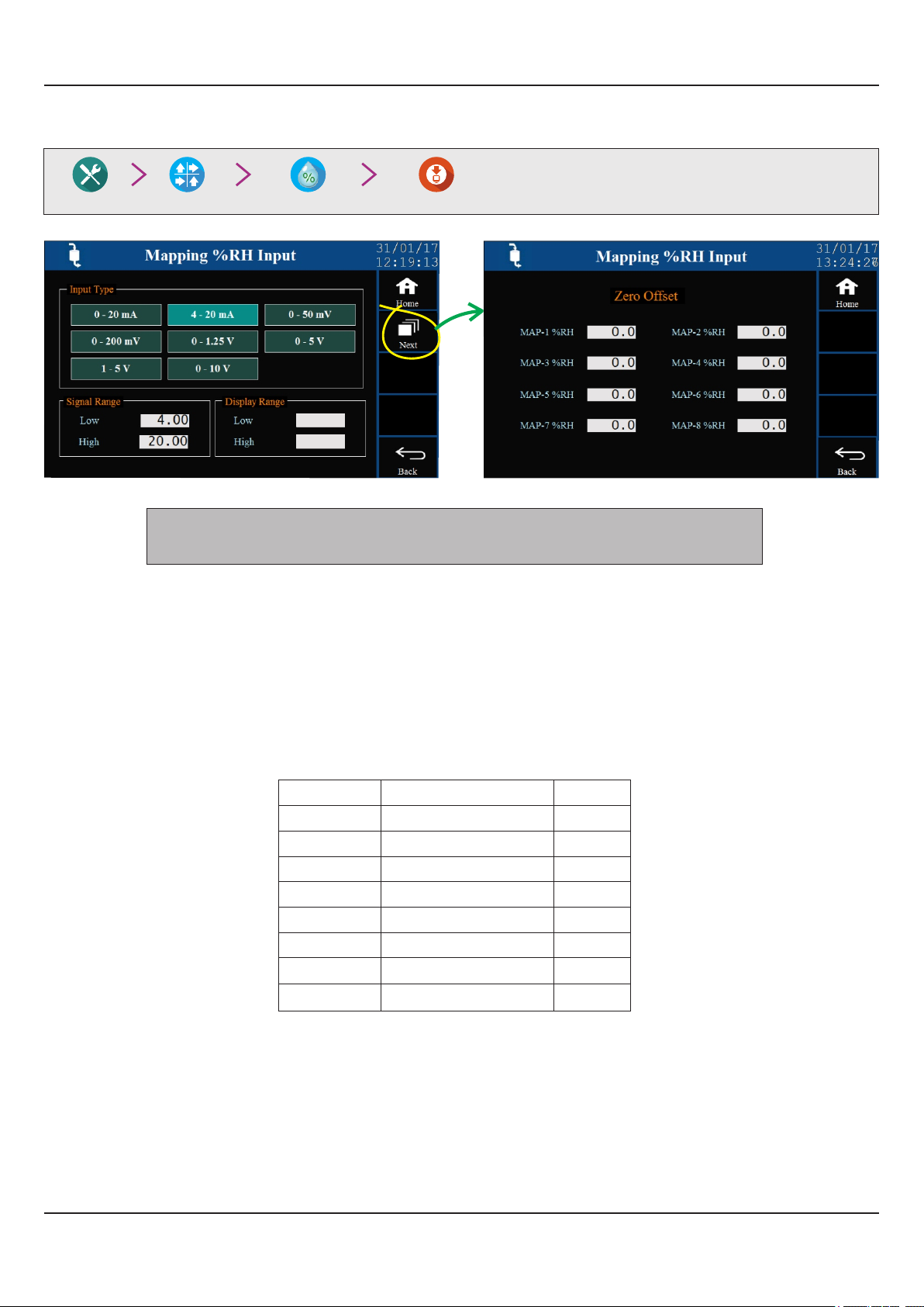
Factory Mapping Input Settings
%RH
0.0
100.0
All the arameter settings, except Zero Offset, on this screen are Common for all p
%RH Inputs.
Input Type
Options : 0 to 20 mA, 4 to 20 mA, 0 to 50 mV, 0 to 200 mV, 0 to 1.25 V, 0 to 5 V, 1 to 5 V, 0 to 10 V
Default : 0 to 5 V
Select Input type in accordance with the type of sensors / transmitters connected for measurement on all %RH Inputs.
Signal Range Low
(Available for DC Linear Volts & mA Inputs only)
Input Type
0 to 20 mA
4 to 20 mA
0 to 50 mV
0 to 200 mV
0 to 1.25 V
0 to 5 V
1 to 5 V
0 to 10 V
Settings
0.00 to Signal High
4.00 to Signal High
0.00 to Signal High
0.0 to Signal High
0.000 to Signal High
0.000 to Signal High
1.000 to Signal High
0.00 to Signal High
Default
0.00
4.00
0.00
0.0
0.000
0.000
1.000
0.00
This parameter is the transmitter output signal value that corresponds to the Range Low process value. Refer Appendix-A :
DC Linear Signal Interface for details.
Signal Range High
(Available for DC Linear Volts & mA Inputs only)
45

HumiTherm Ultra User Manual
Input Type
0 to 20 mA
4 to 20 mA
0 to 50 mV
0 to 200 mV
0 to 1.25 V
0 to 5 V
1 to 5 V
0 to 10 V
This parameter is the transmitter output signal value that corresponds to the Range High process value. Refer Appendix-A :
DC Linear Signal Interface for details.
Display Range Low
Range : .0 % to Range High0
Default : 0.0 %
This parameter is the Process Value that corresponds to the Signal Low value from the transmitter ( ).0 mA or 0 mV or 0/1 V
Display Range High
Range : Range Low to .100 0 %
Default : 100.0 %
This parameter is the Process Value that corresponds to the Signal High value from the transmitter (20 mA or 50/200 mV or
5/10V).
Settings
Signal Low to 20.00
Signal Low to 20.00
Signal Low to 50.00
Signal Low to 200.0
Signal Low to 1.250
Signal Low to 5.000
Signal Low to 5.000
Signal Low to 10.00
Default
20.00
20.00
50.00
200.0
1.250
5.000
5.000
10.00
Zero Offset
Range : -50.0 to 50.0 %
Default : 0.0 %
This parameter value is individually set for each Input (4 8). This value is algebraically added to the measured %RH or %RH
Value to derive the final Value that is displayed and compared for alarm / control. Use this value to nullify any known constant
error.
Final Value = Measured Value + Offset
46

HumiTherm Ultra User Manual
APPENDIX - A
DC LINEAR SIGNAL INTERFACE
This appendix describes the parameters required to interface process transmitters that produce Linear DC Voltage (mV/V) or
Current (mA) signals in proportion to the measured process values. A few examples of such transmitters are;
1. Pressure Transmitter producing for 4 to 20 mA 0 to 5 psi
2. Relative Humidity Transmitter producing for 1 to 4.5 V 5 to 95 %RH
3. Temperature Transmitter producing for 0 to 20 mA -50 to 250 °C
The instrument (indicator/controller/recorder) that accepts the linear signal from the transmitter computes the measured
process value by solving the mathematical equation for Straight-Line in the form:
Y
Y = mX + C
Where;
X : Signal Value from Transmitter
Y : Process Value Corresponding to Signal Value X
C : Process Value Corresponding to X = 0 (Y-intercept)
m : Change in Process Value per unit Change in Signal Value (Slope)
C
Process Value
Y = mX + C
m = / ΔY ΔX
Transmitter Signal
ΔY
ΔX
X
As is evident from the aforementioned transmitter examples, different transmitters produce signals varying both in Type
(m /V/mA) and . Most PPI instruments, thus, provide programmable Signal Type and Range to facilitate interface with V Range
a variety of transmitters. A few industry standard signal types and ranges offered by the PPI instruments are: 0-50mV, 0200mV, 0-5 V, 1-5 V, 0-10V, 0-20 mA, 4-20 mA, etc.
Also, the output signal range (e.g. 1 to 4.5 V) from different transmitters corresponds to different process value range (e.g. 5 to
95 %RH); the instruments thus also provide facility for programming the measured process value range with programmable
Resolution.
The linear transmitters usually specify two signal values (Signal Low and Signal High) and the corresponding Process Values
(Range Low and Range High). In the example Pressure Transmitter above; the Signal Low, Signal High, Range Low & Range
High values specified are: 4 mA, 20 mA, 0 psi & 5 psi, respectively.
In summary, the following 6 parameters are required for interfacing Linear Transmitters:
1. Input Type : Standard DC Signal Type in which the transmitter signal range fits (e.g. 4-20 mA)
2. Signal Low : Signal value corresponding to Range Low process value (e.g. 4 mA)
3. Signal High : Signal value corresponding to Range High process value (e.g. 20 mA)
4. PV Resolution : Resolution (least count) with which to compute process value (e.g. 0.01)
5. Range Low : Process value corresponding to Signal Low value (e.g. 0.00 psi)
6. Range High : Process value corresponding to Signal High value (e.g. 5.00 psi)
47

HumiTherm Ultra User Manual
The following examples illustrate appropriate parameter value selections.
Example 1: Pressure Transmitter producing for 4 to 20 mA 0 to 5 psi
Y (psi)
Presume the pressure is to be measured
Range High
5.00
with 0.01 Resolution, that is 0.00 to 5.00 psi.
Input Type : 4-20 mA
Signal Low : 4.00 mA
Signal High : 20.00 mA
PV Resolution : 0.01
Range Low
0.00
4.00 20.00
Signal Low Signal High
X (mA)
Range Low : 0.00
Range High : 5.00
Example 2: Relative Humidity Transmitter producing for 1 to 4.5 V 5 to 95 %RH
Y (% RH)
Presume the humidity is to be measured
with 0.1 Resolution, that is 0.0 to 100.0 %.
Range High
95.0
Input Type : 0-5 V
Signal Low : 1.000 V
Signal High : 4.500 V
Range Low
5.0
0
0 5
1.000 4.500
Signal Low Signal High
X (V)
PV Resolution : 0.1
Range Low : 5.0
Range High : 95.0
Example 3: Temperature Transmitter producing for 0 to 20 mA -50 to 250 °C
Y (°C)
Range High
250.0
Presume the Temperature is to be measured
with 0.1 Resolution, that is -50.0 to 250.0°C.
Input Type : 0-20 mA
Signal Low : 0.00 mA
Signal High : 20.00 mA
PV Resolution : 0.1
Range Low
-50.0
0
0.00
Signal Low
20.00
Signal High
X (mA)
Range Low : -50.0
Range High : 250.0
48

HumiTherm Ultra User Manual
The following table list various parameters related to DC linear signal input interface & their respective locations.
Parameter Name
Main & Standby
Temperature Control Sensors
Temperature Input Type
Temperature Signal Low
Temperature Signal High
Temperature Range Low
Temperature Range High
Main & Standby
%RH Control Sensors
%RH Input Type
%RH Signal Low
%RH Signal High
%RH Range Low
%RH Range High
Temperature Mapping Sensors
Temperature Input Type
Temperature Signal Low
Temperature Signal High
Temperature Range Low
Temperature Range High
Factory
Navigation
(Where to Locate)
Temperature
%RH
Mapping Input Settings
Input SettingsFactory
Input SettingsFactory
Temperature
%RH Mapping Sensors
%RH Input Type
%RH Signal Low
%RH Signal High
%RH Range Low
%RH Range High
Mapping Input SettingsFactory
%RH
49

HumiTherm Ultra User Manual
APPENDIX - B
COMPRESSOR SETTING PARAMETERS
Compressor Switching Strategies
The PPI “Temperature + Humidity” composite controllers offer different programmable strategies for compressor switching to
meet different design approaches by the manufacturers of Humidity Chambers. The various strategies and the
implementations are described here.
1. Compressor Off
The compressor is kept Off. This trategy is usually selected for emperature values significantly above the ambient s t
temperature.
2. Comp Onressor
The compressor is kept On regardless of the measured or set temperature value. This trategy is usually selected for s
t belowemperature values significantly the ambient temperature.
3. SP Based Strategy
In this strategy, the chamber temperature range is split in two zones by setting the parameter 'Boundary Set-point' (BSP).
Refer Figure below.
70°C
Temp. Control SP in
Compressor Status
45°C
30°C
0°C
ON
OFF
Heat Pre-dominant Zone
Temp. Control SP in
Cool Pre-dominant Zone
50°C
Boundary Set-point
The zone at and above the boundary SP ( ) is referred as Heat Pre-dominant zone and that below the boundary SP ) (
is referred as Cool Pre-dominant zone. The controller automatically switches between the two zones depending upon the
Temperature SP. If the Temperature SP is below boundary SP, Cool Pre-dominant zone is active and the compressor is kept
ON. If the Temperature SP is at or above boundary SP, Heat Pre-dominant zone is active and the compressor is kept OFF. This
strategy eliminates the need for the user to manually switch the compressor ON or OFF.
I Control Zones “Dual”; separate tuning can be performed in the Cool and Heat Pre-dominant zones for f the parameter is set to
accurate control in each zone. The controller maintains separate sets of Proportional Band, Integral Time & Derivative Time
constants for each zone that are automatically selected and used by the controller depending upon the active zone.
However, if the parameter Control Zones is set to “Single”; the controller uses a single set of Proportional Band, Integral Time
& Derivative Time constants for both zones.
50

HumiTherm Ultra User Manual
4. PV Based Strategy
In this strategy, the compressor is switched to cool down the chamber air temperature. The controller switches the
compressor ON or OFF based on the comparison between the chamber temperature value and the SP. Temperature
Refer Figure below.
Measured Temperature
Temperature SP
Compressor Switch-ON Level
Compressor Switch-OFF Level
Temperature SP = 20.0°C
Compressor Set-point = 1.0°C
Compressor Hysteresis = 1.2°C
Compressor Switch-ON Level = 20.0 + 1.0 = 21.0°C
Compressor Switch-OFF Level = 21.0 - 1.2 = 19.8°C
Compressor
Status
21.0
20.0
19.8
ON
OFF
°C
The compressor is turned ON if the chamber air temperature value is above the SP by an amount set by the Temperature
parameter 'Compressor Set-point'. That is;
Compressor Switch - ON Level = (Temperature SP) + (Compressor Set-point)
Once the air temperature falls below Compressor Switch-ON Level by an amount set by the parameter 'Compressor
Hysteresis', the compressor is turned OFF. That is;
Compressor Switch - OFF Level = (Compressor Switch-ON Level) – (Compressor Hysteresis)
The hysteresis inserts a dead band between the Compressor Switch-ON Level and Compressor Switch-OFF Level to avoid
frequent switching of the compressor.
Compressor Time Delay
Once the compressor is switched off, a time delay is desired before it is turned ON again. The time delay prevents the possible
damage due to short cycling. When the compressor switches off, it spins backward as pressure equalizes. If compressor is
energized while it is still spinning backward, it continues to run backward until it trips on internal overloads. This may cause
damage to the compressor.
The time delay cycle is executed every time the compressor is turned off. The compressor turning off may be a result of power
failure or the on-off control algorithm executed by the controller. The controller in “Auto Mode” monitors the Process Value (PV)
against the Set-Point (SP) and attempts to switch the compressor or depending upon whether the PV is or ON OFF above
below the SP.
The time delay starts counting down from the instance the compressor is switched off. The compressor is inhibited from
switching-on until the delay elapses regardless of the difference between the PV and SP. Once the time delay is elapsed, the
control algorithm switches the compressor ON as and when the PV is above SP.
51

HumiTherm Ultra User Manual
°C
PV (Temperature)
SP
Compressor Switch-ON Level
Compressor Switch-OFF Level
Temperature SP = 20.0°C
Compressor Set-point = 1.0°C
Compressor Hysteresis = 1.2°C
Compressor Switch-ON Level = 20.0 + 1.0 = 21.0°C
Compressor Switch-OFF Level = 21.0 - 1.2 = 19.8°C
Compressor
Status
21.0
20.0
19.8
ON
OFF
Case 2 Case 3Case 1
The figure above illustrates 3 cases. Case (1) illustrates power-up delay. In case (2); the time elapses before PV rises above
the SP. The compressor is thus switched ON as soon as the PV rises above the SP. In case (3); the PV rises above the SP while
the time delay is still in progress. The compressor is switched ON as soon as the delay time elapses.
The following table list various parameters related to Compressor Switching Mode / Operation & their respective locations.
Parameter Name
Navigation
(Where to Locate)
Mode
Boundary SP
Time Delay
Hysteresis
Factory
Compressor
Zone Select
52

HumiTherm Ultra User Manual
APPENDIX - C
STANDBY SENSORS
If the Controller is supplied with option, two additional analog inputs are provided for interfacing an additional Standby Sensors
set of temperature & %RH sensors as standby. That is, there are two sets of Sensors; Main & Standby.
Sensor / Transmitter Fail Detection
In case of RTD Pt100 sensor the controller can directly detect Sensor failure through Sensor Open, Over-range or Underrange condition.
For DC linear inputs (mA or Volts), the controller can not detect the transmitter open or short condition. Therefore, the
controller provides two programmable Setpoint Limits, one each for Temperature & %RH. If the measured process value falls
below the respective setpoint limit, the condition is treated as transmitter failure or mal-functioning.
Note the Setpoint Limit for temperature is applicable even if input sensor used for temperature is RTD Pt100.
Main Set Failure
The controller, by default, uses the Main set for measurement, control & alarm purpose. Should any one or both Main Sensors
/ Transmitters fail, the controller automatically switches to the Standby set and stores in its non-volatile memory the Main Set
Failure Main Set Failure condition. The controller continues to work with Standby Set until the condition is cleared from its
memory through Repair Acknowledge button (explained later).
Standby Set Failure
The controller uses the Standby Set only if Main Set Failure condition is stored in its memory. The Main Set Failure condition is
set upon Main Sensor failure detection by controller or manual change over by user from Main Set to Standby Set (explained
later). Should any one or both Standby Sensors / Transmitters fail, the controller switches off all the control outputs and stores
in its non-volatile memory the condition. That is, now both Main & Standby Failure conditions are stored in Standby Set Failure
memory. As long as this condition prevails, the controller behaves like an indicator by keeping all its outputs off. Replace /
repair sensors / transmitters and then use Repair Acknowledge button to bring controller to its normal operation mode.
Manual Switch-over to Standby Set
If the controller is working with the Main Set sensors, the user can switch to Standby Set by using touch push button provided
for this purpose. This feature facilitates the user to use Standby Set should he observe misbehavior in measurement readings
(like continuous fluctuations or intermittent spikes) through Main Set sensors. The manual change-over is treated same as
Main Set Failure condition and is thus stored in memory.
Repair Acknowledge
Once the Main Set and / or Standby Set Failure condition is stored in memory, the only way to clear the same is through Repair
Acknowledge touch button. This feature avoids continuous toggling between Main & Standby Sets should both fail.
Note that Repair Acknowledge button clears both Main & Standby Set Failure conditions from memory.
53

HumiTherm Ultra User Manual
The following table list various parameters related to Standby Sensors & their respective locations.
Parameter Name
Sensor Fail Detection Limit
Temperature Low
%RH Low
Switch to Standby Sensor
Input Sensor Repair
Acknowledge
Navigation
(Where to Locate)
Factory Standby
Supervisory Standby Switchings
Supervisory
Maintenance
Sensor Inputs
54

HumiTherm Ultra User Manual
APPENDIX - D
STANDBY CONTROL GADGETS
If the Controller is supplied with Standby Control Gadgets option, 5 additional digital outputs are provided for interfacing an
additional set of Control Gadgets as standby. That is, there are two sets of Control Gadgets; Main & Standby.
The additional 5 outputs (besides 3 standard outputs, viz., Main Compressor, Main Heater & Main Humidifier) are; Standby
Compressor, Standby Heater, Standby Humidifier, Main Set Select & Standby Set Select. The Main Set Select & the Standby
Set Select outputs are used to drive two external gadgets (usually electromechanical relays) that switch power to SSRs that
drive Main & Standby gadgets respectively. Refer generic electrical connection diagram below.
Line Neutral
+12 V Coil
NO
C
NC
Door Lock
Stby Set Select
Main Set Select
Compressor
Standby
Digital Outputs
Humidifier
Compressor
Main
Humidifier
Heater
Heater
Alarm
Contactor
SSR
Relay
-
+
-
+
-
+
-
+
-
+
-
+
-
+
-
+
-
+
-
+
+12 V Coil
NO
C
NC
+12 V Coil
NO
C
NC
4342414039383736353433323130292827262524
Control Gadget Fail Detection
The term control gadget failure applies to the complete set (Main or Standby) rather than an individual gadget. The failure may
arise due to reasons like heater-break, compressor tripping / failure, SSR output short circuiting, etc. The failure of any gadget
is treated as a set failure and the entire set is switched to the working set.
55

HumiTherm Ultra User Manual
The controller uses Measured Temperature & Low Water Level detection for detecting the control gadget failure.
Temperature Based Detection
For temperature based detection, the controller uses High Deviation Alarm & a Programmable Fail Detect Time (Minutes). If
the measured temperature value crosses the High Deviation Limit & remains there for the set programmed Fail Detect time
then the condition is treated as control gadget failure.
Water Level Based Detection
For water level based detection, the system must implement a float switch and a thermostat. Refer Figure below.
Water Tank Boiler
Water In
Float
Feed Pipe
Thermostat
Steam Out
Heater
The float switch detects water level in the water tank whereas the thermostat detects water level in the boiler. If the thermostat
detects a low water level in the boiler while the float switch indicates that there is sufficient water in the water tank, the condition
is treated as control gadget failure. This situation arises when there is water choking in the feed pipe and thus the steam
generating system needs maintenance.
Time Based Cyclic Switching
When both, Main & Standby, sets are in working condition, the controller periodically switches between the Main & Standby
sets. The periodic time is user settable in Hours.
Note that the working set the elapsed time stored in the memory upon power fail. esumption, the both, and are Upon power r
controller switches the set that was in operation at the time of power failure and ex cutes the balance time.e
Main Set Failure
Upon detecting the Main set failure, the controller automatically switches to the Standby set provided the Standby set is in
working condition. The controller stores in its non-volatile memory the Main Set Failure condition. The controller continues to
work with Standby Set until the Main Set Failure condition is cleared from its memory through Repair Acknowledge button
(explained later).
If the Main Set failure is detected while the Standby set is already failed, the controller switches off all outputs and acts as an
indicator.
Standby Set Failure
Upon detecting the Standby set failure, the controller automatically switches to the Main set provided the Main set is in working
condition. The controller stores in its non-volatile memory the Standby Set Failure condition. The controller continues to work
with Main Set until the Standby Set Failure condition is cleared from its memory through Repair Acknowledge button
(explained later).
If the Standby Set failure is detected while the Main set is already failed, the controller switches off all outputs and acts as an
indicator.
56

HumiTherm Ultra User Manual
Main & Standby Sets Failure
As long as this condition prevails, the controller behaves like an indicator by keeping all its outputs off. Replace / repair the
faulty control gadget(s) and then use Repair Acknowledge button to bring controller to its normal operation mode.
Manual Switch-over
If both, Main & Standby, sets are the user can switch from Main to Standby Set or vice-a-versa by using touch push button
provided for this purpose.
Repair Acknowledge
Once the Main Set and / or Standby Set Failure condition is stored in memory, the only way to clear the same is through Repair
Acknowledge touch button. This feature avoids continuous toggling between Main & Standby Sets should both fail.
Note that Repair Acknowledge button clears both Main & Standby Set Failure conditions from memory.
Inhibit Timer
The controller provides a programmable timer (in hours) for setting a time interval during which the controller ignores the
Control Gadget Fail Detection. This timer is activated upon the following conditions.
1. After recovery from Door Open Alarm
2. Switching over from Auxiliary Power Source (Battery / Inverter) to Mains Power Source
3. System Power-up
4. After automatic / manual changeover from Main control set to Standby control set or vice-a-versa
5. After Repair Acknowledgment
6. After completion of Auto Tuning
The following table list various parameters related to Standby Sensors & their respective locations.
Parameter Name
Navigation
(Where to Locate)
Switch Main / Standby
Output
Supervisory Standby Switchings
Control Gadgets Repair
Acknowledge
Supervisory
Maintenance
Water Level Settings
Float
Detection Enable / Disable
Low Level Logic (Open / Close)
Thermostat
Detection Enable / Disable
Factory
Water Level
Low Level Logic (Open / Close)
Common Boiler (Yes / No)
Standby Control Gadgets
Fail Detect Time (Min)
Cyclic Time (Hrs.)
Factory Standby Control Gadgets
Inhibit Time (Hrs.)
57

HumiTherm Ultra User Manual
APPENDIX - E
DOOR LOCK
If the Controller is supplied with Door Lock option, an additional digital output is provided for operating an electro-mechanical
(Solenoid driven) locking system through an external relay / contactor. For automatic operation of the lock by the controller, the
cabinet door must also be installed with Door Open detect switch that should be connected to the controller digital input
labeled 'Door Open'.
Door “Lock” Operation
Upon power up if the cabinet door is detected the controller locks the door. However if the door is detected upon closed, open
power up, the controller waits until the door is detected before applying the lock. closed
Similarly, when the cabinet door is closed after opening (through appropriate password entry by authorized person) the
controller immediately applies the lock.
Door “Unlock” Operation
The HMI provides independent password entry for up to 7 authorized persons. Each person is identified by a unique ID (1
to 7) and a corresponding 8 character alpha-numeric password as shown below.
ID
1
2
3
Password
ABCDEFGH
12345678
WXYZ9876
4
5
6
7
If less than 7 persons need to be authorized then the password field for the unused ID must be left blank. The figure above
shows only three persons authorized to open door.
The unique ID on the HMI side is mapped with a corresponding entry describing person's name / position on the PC software
(ProLog).
For unlocking the cabinet door the authorized person must enter his password on the HMI screen. Upon correct password
entry the door lock is opened and an Event Record is generated by the HMI containing the authorized person's ID. The Event
Record thus generated is used by the PC software to describe the door open action along with the name / position of the
responsible person in Audit Trail Report.
58

HumiTherm Ultra User Manual
APPENDIX - F
DIGITAL INPUTS & OUTPUTS
DIGITAL INPUTS
The microPLC Control Unit incorporates interfaces for potential-free digital inputs for various functions described below.
Power Fail
This Digital Input is used if provision is made for running the controller on an auxiliary power sources like battery or inverter and
a Switch is mounted for detecting main power source failure. This input detects whether the controller is being powered from
Main or Auxiliary power source.
Door Open
This Digital Input is used to warn if the ch mber door is left open for more than a user programmed time period by activating the a
Alarm. Also a record is generated each time the door is opened or closed.
Water Level
This Digital Input can be used to detect Low Water Level in the Steam generating boiler by mounting a Float / Water Level
Switch. pon det cting Low Water Level, the boiler supply is cut-off and Alarm is U e activated for safety.
Thermostat
This Digital Input can be connected to a thermostat to detect Low Water Level to change over from Main Control Gadget Set to
Standby Control Gadget Set and vice-a-versa. The Thermostat used is set to 110 °C and is immersed in boiler water. So long
as the water level is normal, the thermostat remains immersed and the temperature is below 100 °C. Under Low Water Level
condition, the thermostat gets exposed to air and the temperature eventually rises above 110 °C and the thermostat trips.
Alarm Acknowledge
This Digital Input can be used to mute the larm utput elay.A O R
DIGITAL OUTPUTS
The microPLC Control Unit provides several digital outputs for Alarm & Process Control. The outputs are voltage levels rated
12 VDC @ 40 mA each.
Heater
This Digital Output switches in accordance with the output power computed by PID loop controlling the Temperature. The
output drives the heating element through external Relay / SSR.
Humidifier
This Digital Output switches in accordance with the output power computed by PID loop controlling the %RH. The output
drives the boiler heater through external Relay / SSR.
Compressor
This Digital Output switches in accordance with the On-Off Strategy & Time-Delay set for the compressor operation for cooling
/ de-humidification. The output drives the power to compressor through external Relay / SSR.
59

HumiTherm Ultra User Manual
Main Set Select
Standby Set Select
These Digital Output are fitted and functional only if controller is supplied with Standby Output feature. The digital outputs
control external electrical switches (like contactors) that, in turn, control the power to the relay / SSR sets that drive control
gadgets (Heater, Humidifier & Compressor).
Door Lock
This Digital Output can be used to switch an electro-mechanical (magnetic) lock for cabinet door opening. The door usually
remains locked and is opened only upon correct password entry by the authorized person.
Alarm
This Digital output can be used to activate an audio / visual device under process alarm condition.
60

HumiTherm Ultra User Manual
Process Precision Instruments
101, Diamond Industrial Estate, Navghar, Vasai Road (E),
Dist. Palghar - 401 210.Maharashtra, India
0250 - 2391722/33/37/42 07498799226, 09321985369
support@ppiindia.net sales@ppiindia.net,
61
w w w . p p i i n d i a . n e t
May 2017
 Loading...