

Page 1
NT2-210018 Optical Spectrum
Analyzer User Guide
Optical Network
Solutions
A BELDEN BRAND
Page 2

NT2-210018 Optical Spectrum
Optical Network
Solutions
Analyzer User Guide
A BELDEN BRAND
Section 1 - Using This Manual
This manual contains information for the NT2-210018 Touch Screen Hand Held Optical Spectrum Analyzer. This
equipment is touchscreen capable and also has a hard keypad for operation. Note: there are a few operations only
accessible with touchscreen operation.
This user guide is written primarily using the touchscreen operation with occasional mention of the hard key
equivalents.
There are warnings, cautions and notes, as described below, displayed throughout this manual. Please follow all
warnings and cautions for your safety and the protection of the equipment.
Warning
• A warning alerts to situations that could cause personal injury.
Caution
• A caution alerts to situations that may cause damage to the equipment or produce poor testing
conditions, resulting in inaccurate test results.
Note
• A note is a special annotation that will assist the user with operational features.
Section 2 - Safety
Section 2 of this manual is a quick start guide. Prior to using the quick start guide or operating the equipment, it is
highly suggested the user reads all safety information rst.
This product has been designed and tested in accordance with the manufacturer’s safety standards and has been
supplied in a safe condition.
Below are warnings that must be followed by the user to ensure safe operation and to maintain the product is in a
safe condition. Failure to follow these safety warnings, can result in damage to the instrument or harm to the user.
Warning
Personnel should always be aware when working with ber optic test equipment that active bers may
be present and therefore infrared optical energy may be present.
Warning
Never look directly into the end of a connected ber optic cable or ber optic adapter of test equipment, to do
so could expose the user to laser radiation and could result in severe personal injury.
Warning
To Prevent Fire or Shock Hazard:
• Do not install battery types other than those specied by the manufacturer
• Do not use the charger without the batteries installed
• Do not expose the battery charger to rain or excessive moisture
• Do not use the AC adapter when there are signs of damage to the enclosure or cord
• Ensure you are using the correct charger for the local line voltage
• Do not use any other charger than the one provided with this instrument
• Failure to follow these cautions may damage the equipment and void the warranty
6176 E. Molloy Rd. East Syracuse, NY 13057 U.S.A. • [email protected] • 1-800-800-6652 • +1 315-431-7200 • www.ppc-online.com
2
Page 3
NT2-210018 Optical Spectrum
Optical Network
Solutions
Analyzer User Guide
Caution
Fiber optic connectors are easily contaminated or damaged. The connection to the NT2-210018 is a physical
contact type of connection and dirty or damaged connectors may impair the instrument's capabilities at
minimum, and at worst result in the need to return the NT2-210018 to the factory for expensive repairs. Prior
to making any connection to the unit, ensure all proper cleaning procedures have been followed.
Use UPC Finish Connectors Only!
Caution
The NT2-210018 has two ports: a low power and high power port. The low power port is designed for maximum power of -10dBm per channel and a maximum composite power of +22dBm. The high power port is
designed for a maximum of +10dBm per channel and a maximum composite power of +29dBm. If you are unsure of the power level, it is best to start in high power mode and use the designated high power port. Please
refer to Section 8.1 of this manual for instructions on setting the power level.
A BELDEN BRAND
Section 3 - Quick Start Guide
Press the POWER button to turn on the NT2-210018
Operation
The port/power setting dialog will be displayed. It indicates the current power setting and which port should be
used at that setting. Touch any button or the screen to close this dialog. There are two testing ports: low is for
testing up to -10dBM and high for testing up to +10dBm. For accurate readings, it is necessary to use the proper
port with the proper setting.
If the power is not set to the desired level, enter the menu and select power to change the power level, as required.
Icon Menu
To enter MENU, either press the button or use the stylus to pull the icon menu up from the bottom of
the screen.
Available icons:
Help – displays an on-board explanation of features, functions and operations
Bar graph – touching this icon returns the user to the bar graph
File icon – touching this icon will bring the user to the le management menu
Settings icon – touching this icon brings the user to the OSA and general settings menus
Scope icon – this will open the video scope feature
Table icon – this is used to open the table display of data
Note
Most features of the NT2-210018 are accessible with either the touchscreen or the hard buttons on the
keypad. This quick start will primarily focus on the touchscreen.
6176 E. Molloy Rd. East Syracuse, NY 13057 U.S.A. • [email protected] • 1-800-800-6652 • +1 315-431-7200 • www.ppc-online.com
3
Page 4

NT2-210018 Optical Spectrum
Optical Network
Solutions
Analyzer Users Guide
Note
On start-up, there is a short warm-up period before the OSA can scan. The scan indicator is in the bottom right
of the display. It shows yellow, red and green. Yellow is warming up; red is ready to scan; and green is scanning.
This indicator may be used with the stylus to start and end a scan.
Scan
Once the unit is ready to scan, touch the scan indicator or the scan button on the keypad to start the scan.
To stop a scan, touch the scan indicator or press the scan button again.
Cursor Movement/Selection:
To move the cursors, touch the screen and the active will snap to that location. Moving the stylus up or down on
the display will drag the cursor as desired.
Note
Touching the left hand channel number bar is a quick method to switch to the table display and touching the
left most channel number bar on the table display will revert back to the graph display. Therefore, it is necessary to stay clear of this area when manipulating the cursors with the touch screen.
To change the active cursor, touch the red or blue cursor points on the right side of the display. The one outlined in
black is the active cursor (A/B button on the keypad).
A BELDEN BRAND
Auto Test/Zoom: (Keypad only)
The Auto Test button automatically zooms to active channels. This is the rst channel starting at channel 1 that is
higher than -45dBm in low power mode (-25dBm in high power mode). It sets that as the rst channel in the visible
range then starts at the last channel and works backward to nd the last channel that meets the same criteria and
sets it as the last channel in the visible range. This button toggles this feature on and o.
Please review the remainder of this user guide for full instructions on using
the NT2-210018 Optical Spectrum Analyzer
6176 E. Molloy Rd. East Syracuse, NY 13057 U.S.A. • [email protected] • 1-800-800-6652 • +1 315-431-7200 • www.ppc-online.com
4
Page 5
NT2-210018 Optical Spectrum
Optical Network
Solutions
Analyzer User Guide
A BELDEN BRAND
Section 4 - Introduction
Terahertz Technologies NT2-210018 Handheld Optical Spectrum Analyzer oers full featured analysis of DWDM
systems in a truly handheld portable package. DWDM optical levels in the C-band (1530.4-1565.1 nm or 195.90 -
191.55 THz) may be measured with a resolution of 0.01nm, and measurement levels range from +10 to -50dBm.
Parameter settings to optimize the resolution, number of channels displayed, power levels displayed or set the rst
channel to match the system under test allows for easy and accurate analysis of DWDM scans. Channel spacing
may be set at 50 or 100 GHz with 88 Channels on the ITU Grid. This unit has fast acquisition time of two scans per
second. The information may be viewed in graph mode or table mode with a pass/fail feature on the 4-inch color
TFT Display. The NT2-210018 is designed with solid state optics and no fragile or moving parts to keep the unit eld
friendly. There is storage for up to 1,000 tests and the test may be viewed and printed with the included CertSoft
software for fast and easy reporting. These units are housed in a rugged enclosure with robust protective boot,
designed to withstand the rigors of eld use and are extremely user friendly.
Section 5 - Preparation For Use
5.1 Inspection
Before shipment, this instrument was inspected and found to be in perfect working order and free of defects.
The shipping carton contains the following:
1. Handheld Optical Spectrum Analyzer, with protective boot and 4-AA NiMH batteries installed
2. Universal AC/DC charger with interchangeable mains
3. USB cable
4. CD with CertSoft software and user manual
5. Set of interchangeable adapters: SC and FC, for each OSA port
5.2 Identication and Conguration
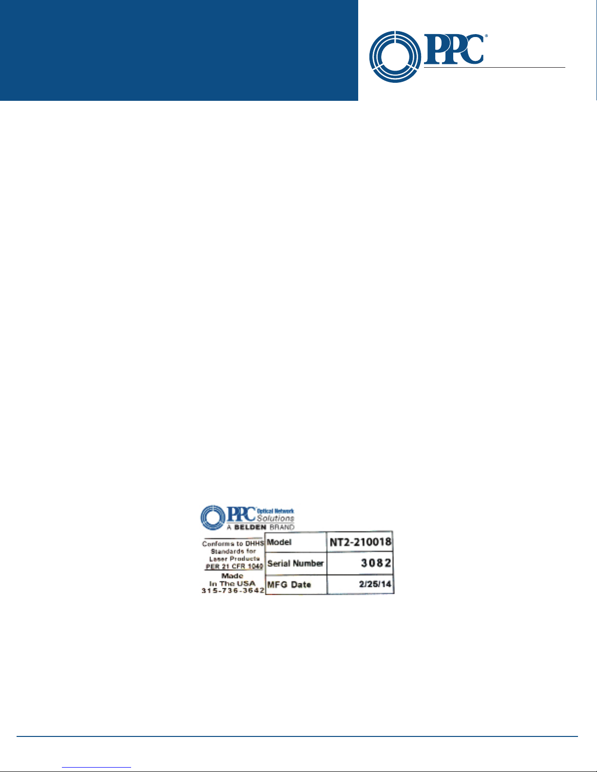
The instrument’s Model/Part Number, Serial Number and Date of Manufacture are indicated on a label located on
the back of the unit. The instrument’s history is led at the factory by Model/Part Number and Serial Number. The
unit's Serial Number is also located on the top plate just above the USB Port.
Fig 5.1
5.3 Power Requirements
The NT2-210018 is equipped with a 100-240V-0.4A input and 9V, 0.67A, center positive output universal AC/DC
battery charger. This charger is supplied with interchangeable mains for US, Great Britain, Europe and Australia.
The unit is shipped with 4-AA NiMH batteries (2500mA hours). Depending on usage, a fully charged battery pack
will typically enable approximately 4 hours of use. Fully discharged batteries require 6 - 8 hours of recharging.
To replace the batteries, remove the OTDR from the protective boot by pulling the bottom of the boot down and
back, allowing the bottom of the unit to be lifted out. The battery door is located on the back side of the unit.
6176 E. Molloy Rd. East Syracuse, NY 13057 U.S.A. • [email protected] • 1-800-800-6652 • +1 315-431-7200 • www.ppc-online.com
5
Page 6
NT2-210018 Optical Spectrum
Optical Network
Solutions
Analyzer User Guide
Replace the batteries with only high quality AA NiMH batteries. Spare battery packs are available with a charging
unit for extended battery operation. If you install NiMH batteries that are dead or less than 1 volt each, charge these
batteries for one hour before using the OTDR. For proper maintenance, batteries require a monthly recharge.
Warning
To Prevent Fire or Shock Hazard:
• Do not install battery types other than those specied by the manufacturer
• Do not use the charger without the batteries installed
• Do not expose the battery charger to rain or excessive moisture
• Do not use the AC adapter when there are signs of damage to the enclosure or cord
• Ensure you are using the correct charger for the local line voltage
• Do not use any other charger than the one provided with this instrument
• Failure to follow these caution statements may void the warranty of this equipment
A BELDEN BRAND
Section 6 - Physical Description
The Optical Spectrum Analyzer is packaged in a rugged aluminum housing which is further protected with
a rubberized boot. Although the front panel is weather resistant, care must be taken to avoid liquids and
contaminants around the fragile optical and electrical connectors, and the glass display. Use a mild cleaning agent
and damp soft cloth to clean the panels and the outside case. See the maintenance section for notes to clean the
optical connector. NEVER open the instrument for cleaning. Return to the factory for servicing if necessary.
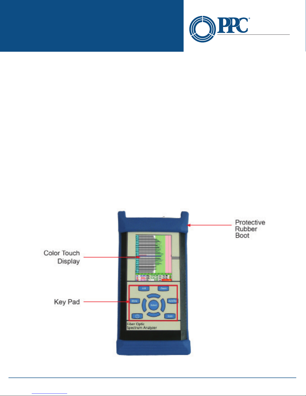
Front Panel
6176 E. Molloy Rd. East Syracuse, NY 13057 U.S.A. • [email protected] • 1-800-800-6652 • +1 315-431-7200 • www.ppc-online.com
Fig 6.1
6
Page 7
NT2-210018 Optical Spectrum
Optical Network
Solutions
Analyzer User Guide
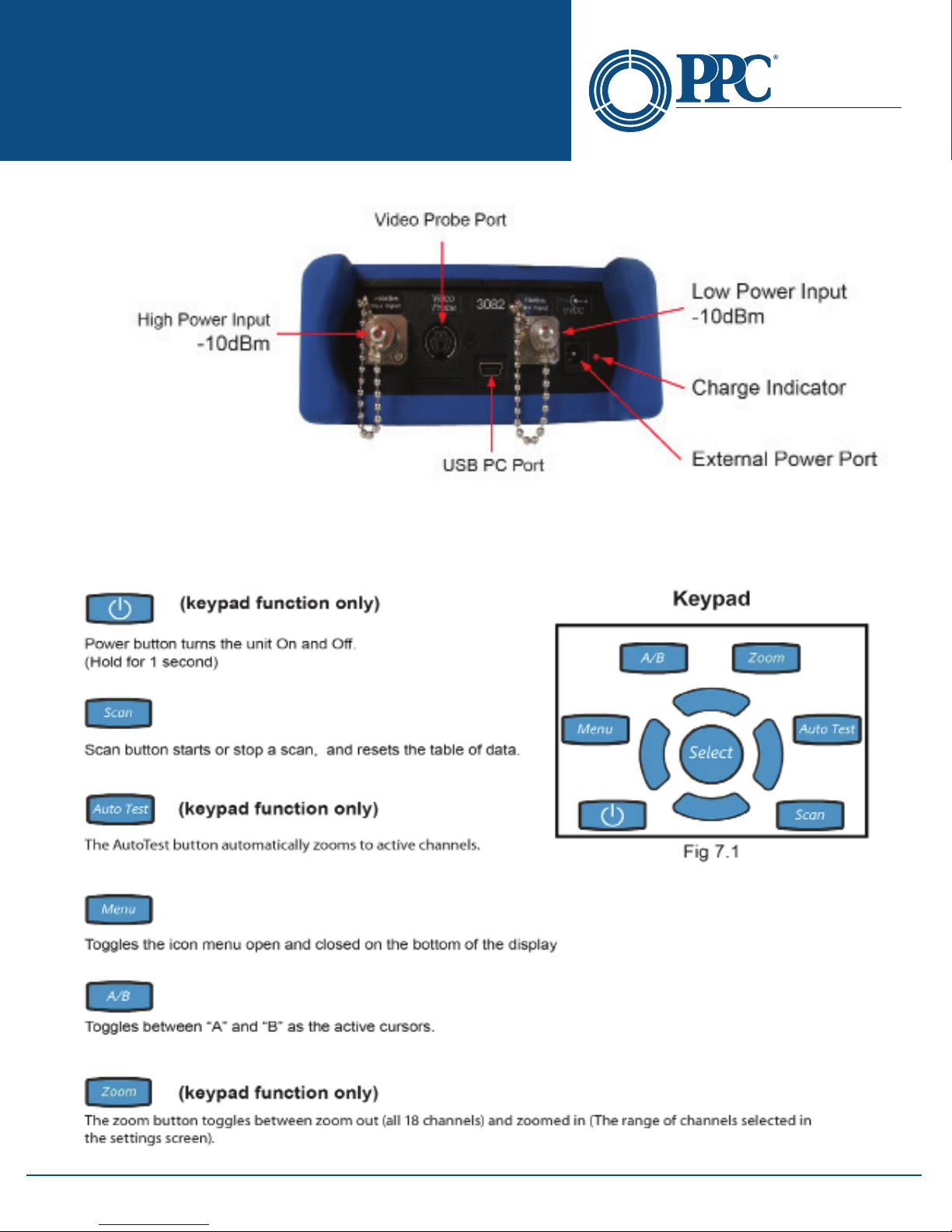
Top Plate
Section 7 - User Interface
7.1 Keypad
A BELDEN BRAND
Fig 6.2
6176 E. Molloy Rd. East Syracuse, NY 13057 U.S.A. • [email protected] • 1-800-800-6652 • +1 315-431-7200 • www.ppc-online.com
7
Page 8
NT2-210018 Optical Spectrum
Optical Network
Solutions
Analyzer User Guide
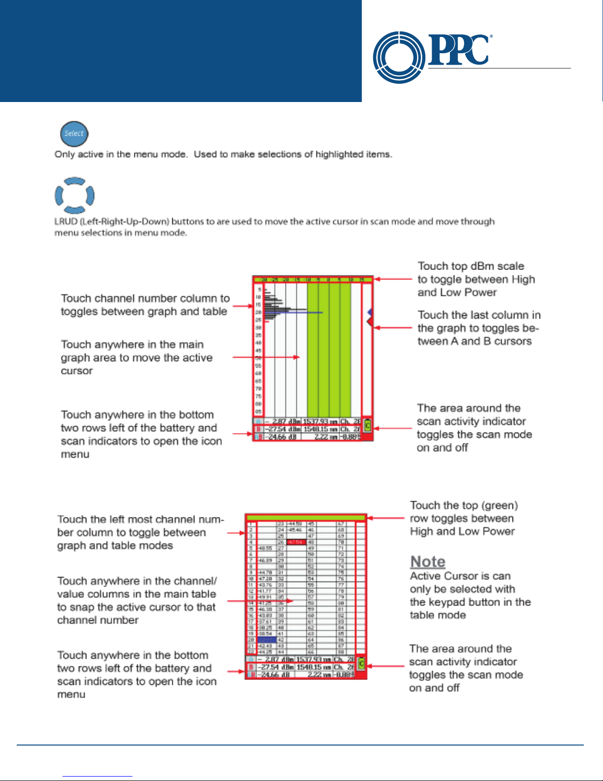
7.2 Touch Display
Graph Mode
A BELDEN BRAND
Fig 7.2
Table Mode
Fig 7.3
6176 E. Molloy Rd. East Syracuse, NY 13057 U.S.A. • [email protected] • 1-800-800-6652 • +1 315-431-7200 • www.ppc-online.com
8
Page 9
NT2-210018 Optical Spectrum
Optical Network
Solutions
Analyzer User Guide
Note
Touchscreen descriptions for Parameter, File Management and Scope screens will be covered in their individual sections.
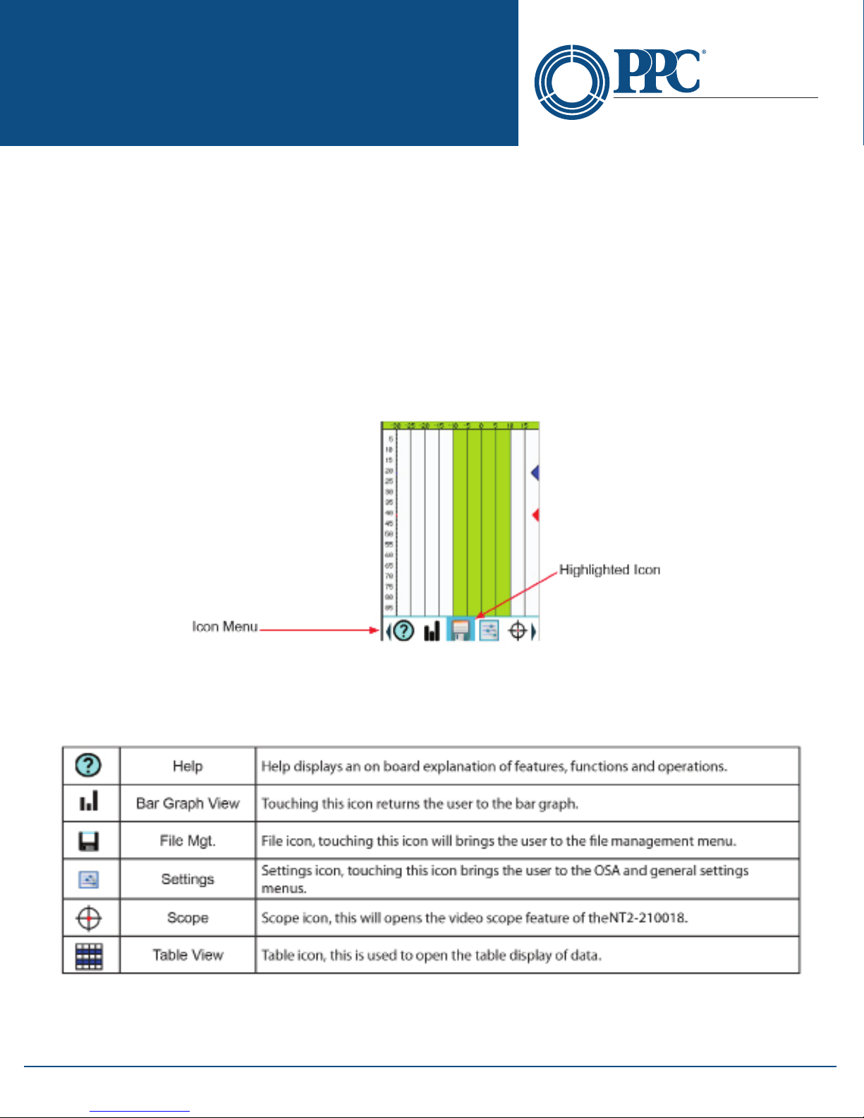
7.1 Icon Menu
Movement between screens and functions is accomplished through a set of icons located in a menu that is
accessed by touching the bottom of the display or pressing the Menu button. To remove the menu from the bottom
of the display, either select an icon, touch the display above the menu or press the Menu button.
To use the icon menu, touch to the left or right of the highlighted icon in the center to move the icons left or right.
The Left and Right buttons may also be used to move the icons. With the desired icon highlighted, touch it or press
the Select button.
Display with Icon Menu Open
A BELDEN BRAND
Icon Descriptions
Below is a list of the icons found in the Icon menu with a brief description of each. More detailed explanations will
be found in later in this user guide.
6176 E. Molloy Rd. East Syracuse, NY 13057 U.S.A. • [email protected] • 1-800-800-6652 • +1 315-431-7200 • www.ppc-online.com
9
Page 10
NT2-210018 Optical Spectrum
Optical Network
Solutions
Analyzer User Guide
A BELDEN BRAND
Section 8 - Settings Screens
To ensure the most accurate and usable information is derived from the OSA, it is necessary to set the testing and
equipment parameters prior to starting a scan.
Test parameters may be set at the time of use or they may be set and stored for later use. These test congurations
are stored in le management.
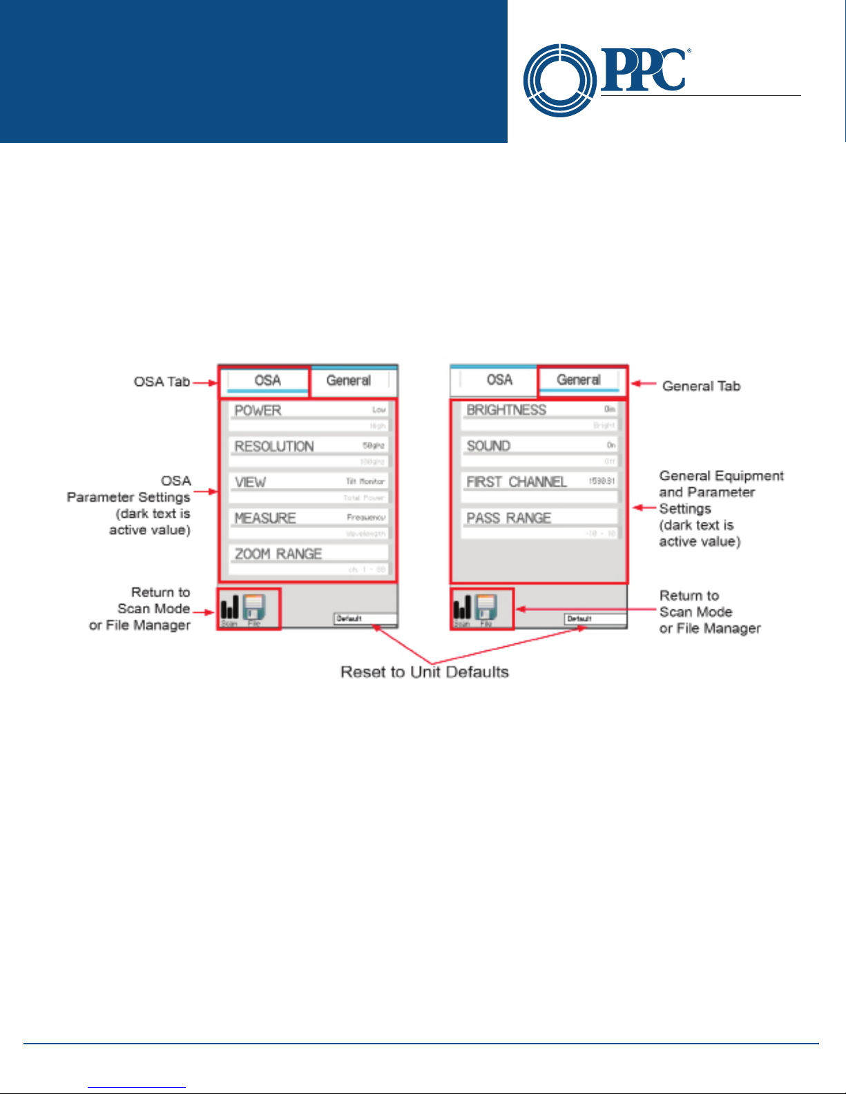
To set testing parameters and general equipment settings, use the Settings screen. To access the Settings screen,
open the Icon menu, highlight the Settings icons and touch it or press Select.
OSA and General Settings Pages
Note
The Directional buttons and the Select button are not operational in the Settings screen.
To select a parameter to be modied, touch it on the display and the Parameter Settings screen will be displayed.
Parameter Settings Screens
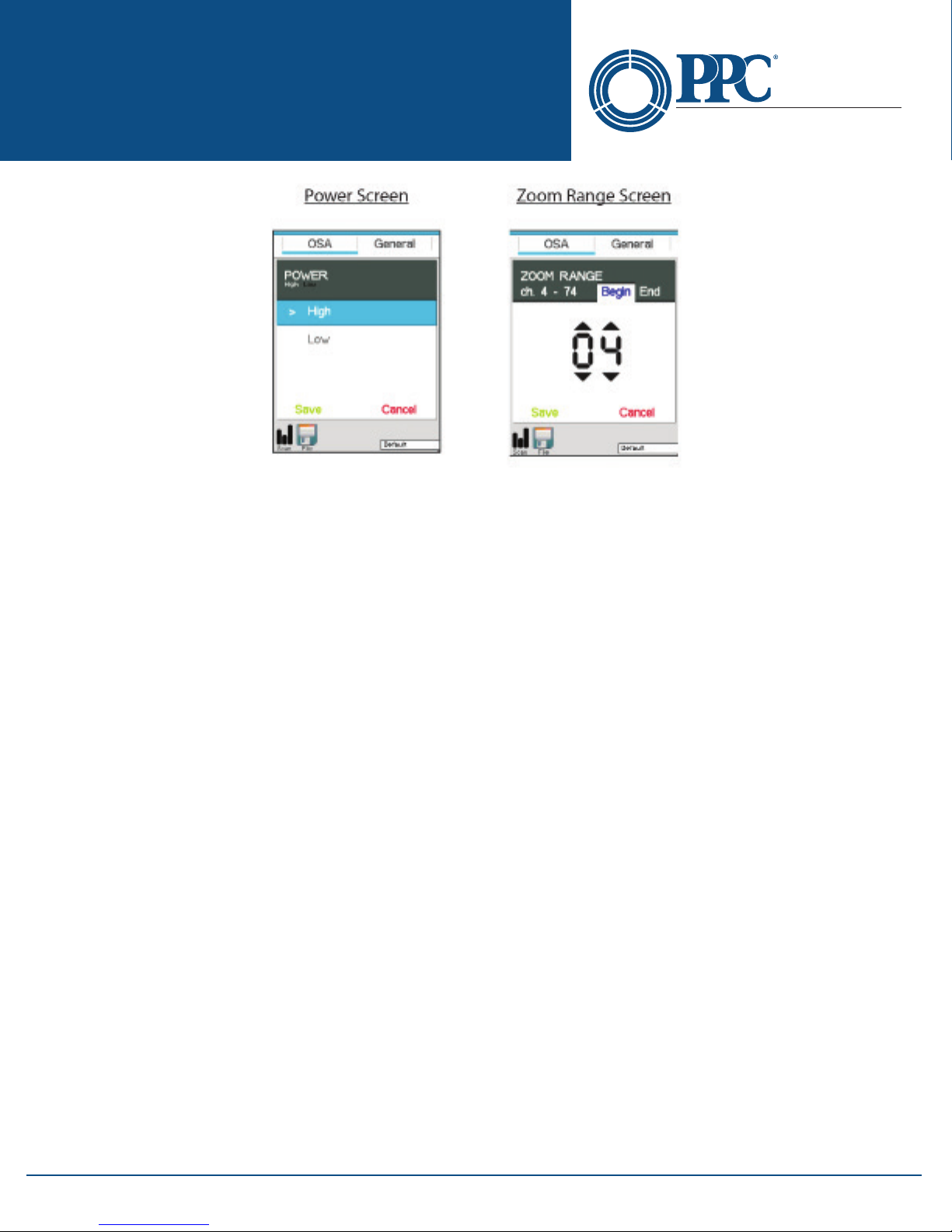
There are two types of parameter screens. The rst, as typied by the Power Setting screen on the next page, oers
a selection of two items. Select the desired value and touch Save. The second type is one where numeric values
are selected. These may have one or two values to be entered. If two values are needed (shown on the zoom range
display below), there will be two tabs, such as Begin and End tabs with this parameter. Use the up arrow above
the digit or the down arrow below the digit to set the value. If necessary, select the second tab and set the second
value. Touch Save to set the values and return to the settings display.
6176 E. Molloy Rd. East Syracuse, NY 13057 U.S.A. • [email protected] • 1-800-800-6652 • +1 315-431-7200 • www.ppc-online.com
Fig 8.1
10
Page 11
NT2-210018 Optical Spectrum
Optical Network
Solutions
Analyzer User Guide
Fig 8.2
8.1 OSA Parameter Tab
Power Level
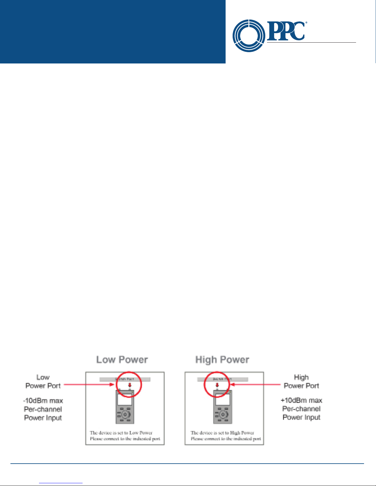
The NT2-210018 has two optical ports: a low power and high power port. The low power port is designed for
maximum power of -10dBm per channel and a maximum composite power of +22dBm. The high power port is
designed for a maximum of +10dBm per channel and a maximum composite power of +29dBm. Upon starting
the NT2-210018, the switch Port dialog will be displayed to indicate the power setting. If the desired power level is
indicated, connect the ber under Test to the port shown and touch the screen or press the Select button to clear
the dialog box. If the wrong power level is indicated, touch the screen to remove, then open the icon menu and
select the Settings icon. Touch the Power setting in the Power Parameter screen, select the desired power and touch
Save, then touch the Scan icon in the bottom left of the display to return to the Graph screen.
A BELDEN BRAND
Note
The power may also be changed quickly by touching the green dBm scale at the top of the display to toggle
between high and low power.
Resolution
The resolution may be set to 50 GHz (0.4 nm) or 100 GHz (0.8 nm) per channel, or High and Low resolution
respectively. At high or low (50 or 100GHz) resolution, the rst channel will be the rst channel as established by
the rst channel setting in the General tab of the Settings screen.
View Setting
The view setting sets the view of the scan to total power or tilt monitoring. Total power is the power being
introduced to the ber. Tilt monitoring is used for both power tilt and gain tilt as described below. In the tilt
monitoring setting, there will be a linear regression line on the display and the value associated with that regression
line is displayed in the bottom right cell.
To display the tilt monitor, enter the Settings screen by bringing up the Icon menu and touching the Settings icon.
Touch the View Setting and select Tilt Monitor. The tilt monitor is now turned on for power and gain tilt.
Power Tilt
Power Tilt, is displayed as a linear regression line overlaid on the graph and as a numeric indicator in the bottom
right of the display. This reading only factors in the channels that are greater than the minimum power level of the
scale. This can be used to assist with balancing the power of DWDM system. The atter (more level) the line, or the
closer to zero the power tilt number, the more balanced the power between channels.
6176 E. Molloy Rd. East Syracuse, NY 13057 U.S.A. • [email protected] • 1-800-800-6652 • +1 315-431-7200 • www.ppc-online.com
11
Page 12

NT2-210018 Optical Spectrum
Optical Network
Solutions
Analyzer User Guide
Gain Tilt
Gain Tilt, is displayed as a linear regression analysis of change in power between the overlapping channels overlaid
on the graph comparing two scans. This reading only factors in the channels that are greater than the minimum
power level of the scale. This is useful when balancing gain from EDFA systems.
A BELDEN BRAND
NOTE
Gain Tilt requires two scans be compared. See below for dual scan operation procedures.
NOTE
All the scan data on the display is the data associated with the primary trace.
There are two methods to display dual scans for a Gain Tilt comparison
With New Scan
Use a scan that has just been acquired using the Scan button. After a scan has been taken, bring up the Icon
menu and select the File Management icon. Make sure the OSA table is highlighted and touch above the blue
highlighted center point to move up through the le list and below to move down the list. With the desired
scan highlighted, touch the Compare icon and the saved OSA scan will be displayed on the screen with the
scan that was just acquired. Please refer to Section 10 for more information on using the le manager. Gain Tilt
only measures those channels that meet the minimum value of the displayed scale.
With Saved Scans
The second method is to use two scans that have already been stored. To do this, enter the le manager as
described and with the OSA tab highlighted, select the primary scan to be used. Touch the le name while it is
highlighted to open it or use the Select button on the keypad. Do not use the Select icon on the le management screen. Enter le management again and with OSA tab highlighted, move the le to be compared to the
highlighted bar and touch the Compare icon. The primary trace will be the rst one selected.
To exit the Gain Tilt mode, open a dierent scan le or start a new scan. To exit the Gain/Power Tilt modes and
return to the total power mode, enter the Icon menu, select the View Parameter, select Total Power and Save.
Measurement
Depending on the system, channels my be listed in wavelength or frequency. To accommodate this, the NT2-210018
may be set to display in nanometers (nm) for wavelength or terahertz (Tz) for frequency. To change these settings, pull
up the Icon menu and touch the Settings icon. Touch Measure Setting, choose frequency or wavelength then touch
Save.
Zoom
The Zoom button is used to zoom in on a specic set of contiguous channels. If the set of channels to be viewed
is channel 20 to 50 for instance, this feature allows the user to set this range, and by pressing the Zoom button on
the keypad, shows only those channels. To set the zoom span, pull up the Icon menu and select the Setting screen.
Touch the Zoom setting and with the Begin tab highlighted, use the up and down arrows on each digit to set the
rst channel to be viewed. To set the last channel, highlight the end tab and set this channel in the same manner as
the beginning channel. Touch Save and touch the Scan icon to return to the graph screen.
8.2 General Parameter Tab
Brightness
Depending on working conditions, a lower level of light may be best for optimal viewing of the OSA. Use this
Brightness setting to toggle between dim and bright settings. To set the brightness level, enter the Settings screen
by bringing up the Icon menu and touching the Settings icon. Touch the General tab and then touch the Brightness
6176 E. Molloy Rd. East Syracuse, NY 13057 U.S.A. • [email protected] • 1-800-800-6652 • +1 315-431-7200 • www.ppc-online.com
12
Page 13
NT2-210018 Optical Spectrum
Optical Network
Solutions
Analyzer User Guide
setting, select dim or bright as desire then touch Save.
Sound
The Sound setting toggles the keystroke speaker on and o. To set the sound on or o, enter the Settings screen
by bringing up the Icon menu and touching the Settings icon. Touch the General tab and then touch the Sound
setting, select on or o as desired and then touch Save.
First Channel
Operating systems my have dierent numbering schemes for their channels. By default, 195.9 THz (1530.3 nm) is
assigned to channel number 1, and depending on the resolution setting, the channel numbers increase in steps
from 50 GHz (0.4 nm) or 100 GHz (0.8 nm). To help sync the NT2-210018 with these systems, it is possible to set the
rst channel to match that of the system being tested. To set the wavelength or frequency of the rst channel, enter
the Settings screen by bringing up the Icon menu and touching the Settings icon. Touch the General tab and then
rst channel. Use the stylus to raise and lower the wavelength/frequency to match that of the system channels, save
and touch the Scan icon in the bottom left of the display to return to the graph screen.
NOTE
It’s important to note that this prevents reading channels below the established rst channel.
Pass Range
For a quick indication of passing channels, the pass range may be set to highlight the power level on the display
for a passing channel. Set this range so channels meeting the passing criteria fall into the green shaded area of the
dBm scale. To set the pass range, enter the Settings screen by bringing up the Icon menu and touching the Settings
icon. Touch the General tab and then Pass Range. Touch the Min tab and use the up and down arrows for each digit
to set the minimum acceptable power for a channel. Touch the Max tab and set the maximum acceptable power for
a channel in the same method. Touch Save to return to the General tab in the Settings screen and touch the Scan
icon in the bottom left of the display to return to the Graph screen.
A BELDEN BRAND
Section 9 - Operation
9.1 Start-up
Press and hold the Power button for one second to start the NT2-210018. Upon startup, the unit will display a notice
indicating the current power setting and direct the user to connect to the high or low power ports. If the incorrect
power is set, follow the instructions in this guide to change the power level. (Section 8.1)
Start-Up Power Level Indicator
Fig 9.1
6176 E. Molloy Rd. East Syracuse, NY 13057 U.S.A. • [email protected] • 1-800-800-6652 • +1 315-431-7200 • www.ppc-online.com
13
Page 14

NT2-210018 Optical Spectrum
Optical Network
Solutions
Analyzer User Guide
Touch anywhere on the display or press the Select button to remove the power level indicator from the display.
Warm-up
There is a warm-up stage for the NT2-210018. The yellow indicator in the bottom right corner of the display
indicates the unit is in warm-up mode. When the indicator turns red the unit is ready to scan and a green indicator
shows the unit is scanning.
A BELDEN BRAND
9.2 Connecting Fiber
It is suggested that a test cable be used between the ber under test and the NT2-210018. This reference ber
should be approximately one meter in length and have minimal loss. The reference cable should be only be
removed from the unit when necessary. Limiting removal and termination of connectors to the unit will extend the
lifespan of the connector, eliminating down time and costly repairs. Only UPC connectors should be used with the
NT2-210018.
Caution
The NT2-210018 has two ports: a low power and high power port. The low power port is designed for
maximum power of -10dBm per channel and a maximum composite power of +22dBm. The high power
port is designed for a maximum of +10dBm per channel and a maximum composite power of +29dBm.
If you are unsure of the power level, it is best to start in high power mode. For more information, please refer
to the Power Level paragraph in this section of the user guide.
Caution
Fiber optic connectors are easily contaminated or damaged. The connection to the NT2-210018 is a
physical contact type of connection and dirty or damaged connectors may impair the instrument's
capabilities at minimum and, at worst, result in the need to return the NT2-210018 to the factory for
expensive repairs. Prior to making any connection to the unit, ensure that all proper cleaning procedures
have been followed. Use UPC Finish Connectors Only!
9.3 Taking Scans
Scanning
There is a short warm-up period for the NT2-210018. This is indicated by the scan indicator in the bottom right of
the display. Yellow is warming up, red is ready to scan and green is scanning.
Once all the parameters have been set, the Scan button may be pressed or the scan indicator may be used on the
touchscreen to start a scan. Pressing the Scan button or touching the Scan Indicator a second time will stop
the scan.
AutoTest
The Auto Test button automatically zooms to active channels. This is the rst channel starting from channel 1 that
is higher than -45dBm in low power mode (-25dBm in high power mode) and setting that as the rst channel in
the visible range, then starting from the last channel and working backward to nd the last channel that meets the
same criteria and setting it as the last channel in the visible range. This button does not start a scan, but focuses
on the channels as described above on recalled scans or active scans. This button toggles this feature on and o,
and sets the span for any scan to follow, until it is pressed a second time. Stored scans will not take the Auto Test
settings from another stored scan, but the setting from a stored scan can be uses on new scans.
Using Stored Congurations
Test congurations are stored in the File Management screen. To use a stored congurations, pull up the Icon menu
and select the File Management icon. Touch the Cong tab; from the le list, highlight the desired conguration
and press select on the keypad or touch the conguration name while highlighted. Scans will now use the
established parameters from the active conguration.
6176 E. Molloy Rd. East Syracuse, NY 13057 U.S.A. • [email protected] • 1-800-800-6652 • +1 315-431-7200 • www.ppc-online.com
14
Page 15
NT2-210018 Optical Spectrum
Optical Network
Solutions
Analyzer User Guide
9.4 Viewing OSA Scans
Graph Display
A BELDEN BRAND
Fig 9.2
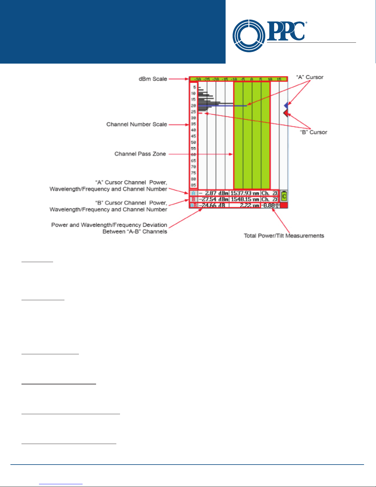
Graph Information
dBm Scale
The dBm scale at the top of the page indicates -50 to 0 dBm when in low power mode and -30 to +20 dBm in high
power mode. This scale allows for a quick estimate of a channel's power. For a highly accurate indication of power,
use the “A” and “B” cursors.
Channel Scale
The Channel Scale displays the channel numbers that may be viewed. The scale is normally 1-88, but may be
changed if the rst channel feature is used. The rst channel setting eliminates the number of channels bypassed
from the total number, and shifts the scale accordingly. This scale is also modied when Zoom is selected. It shifts
the number of channels as selected with the zoom feature. If zoom was set to see only channels 51-60, it would only
display those 10 channels.
Channel Pass Zone
This green highlighted area of the display assists with quick evaluation of channels for pass/fail state. Set this scale
with the pass range setting under the General tab of the Settings Screen.
Cursor Data Information
Channel power, wavelength/frequency and the channel numbers for selected channels are displayed in the data
section at the bottom of the display.
“A” to “B” Cursor Relational Data
The bottom row of the data section indicates the deviation of power and wavelength/frequency between the “A”
and “B” cursors.
Total Power/Tilt Measurements
The total power or tilt information is displayed in the bottom right most cell of the OSA’s measurement table and
graph screen.
6176 E. Molloy Rd. East Syracuse, NY 13057 U.S.A. • [email protected] • 1-800-800-6652 • +1 315-431-7200 • www.ppc-online.com
15
Page 16
NT2-210018 Optical Spectrum
Optical Network
Solutions
Analyzer User Guide
9.5 Cursor Movement
The “A” and “B” cursors may be moved with the touchscreen or the up and down buttons on the keypad.
Set Active Cursor
The cursor to be moved must be set as the active cursor. This is indicated with a black outline around the cursor
point on the right side of the display. To set the active cursor, touch the desired cursor point with the stylus or press
the A/B button on the keypad to toggle between the cursors.
Cursor Movement
To move a cursor, touch anywhere between the channel number column and the cursor point column and the
active cursor will snap to the channel selected. To slide the cursor up and down on the display, touch the display
and slide the stylus up and down to drag the cursor to the desired position/channel number. The up and down
buttons on the keypad will move the cursors as well.
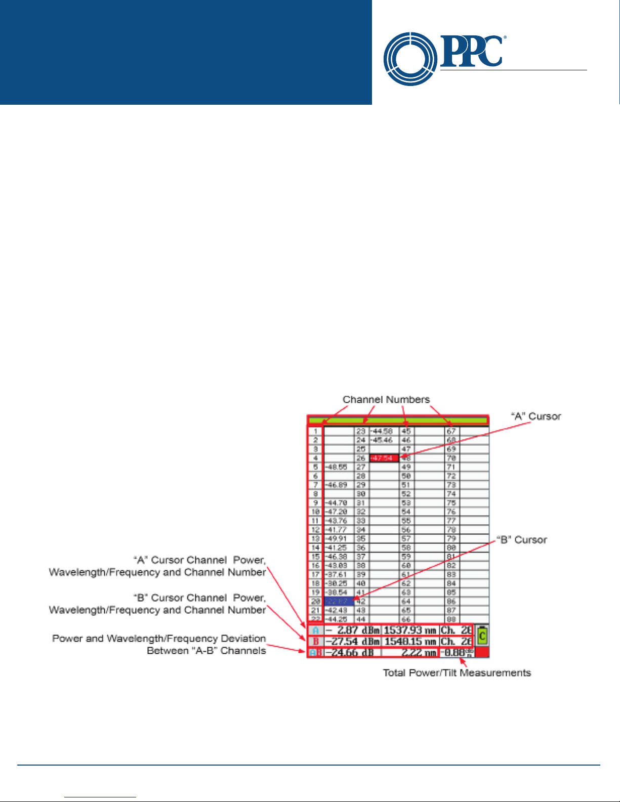
9.6 OSA Table View
The table display oers all the same information as the graph view in a tabular format. Touching any channel value
eld will snap the active cursor to that channel number, or the stylus may be moved up and down the columns to
drag the active cursor.
Note
To toggle between the graphical view and the table view, touch the left most channel number column.
A BELDEN BRAND
Note
Channels that pass based on the pass range setting will have dBm values displayed in green.
6176 E. Molloy Rd. East Syracuse, NY 13057 U.S.A. • [email protected] • 1-800-800-6652 • +1 315-431-7200 • www.ppc-online.com
Fig 9.3
16
Page 17
NT2-210018 Optical Spectrum
Optical Network
Solutions
Analyzer User Guide
A BELDEN BRAND
Section 10 - File Management
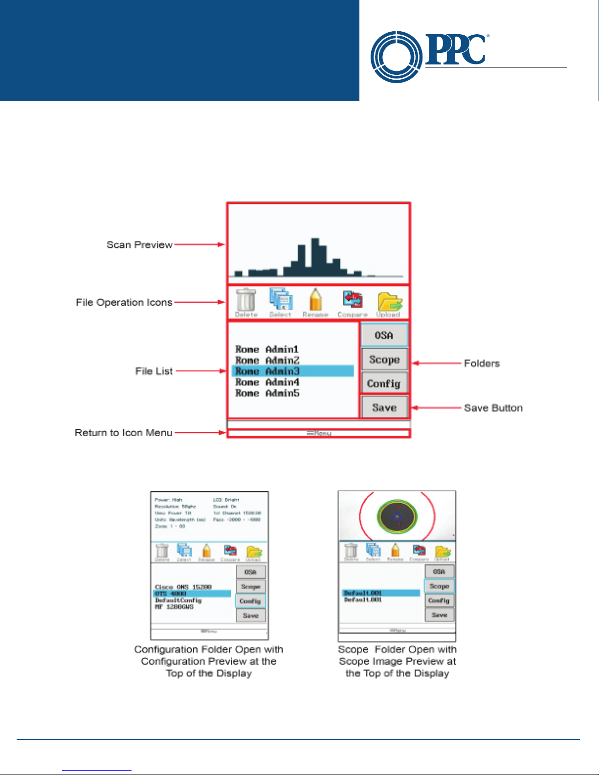
File Management is accessed through the Icon menu. To open the File Management screen, bring up the Icon
menu, highlight the File Management icon and press Select on the keypad or touch the File icon on the display.
10.1 File Management Display
Main File Management Screen (OSA Folder)
Fig 10.1
Conguration and Scope Folder Displays
Fig 10.2
6176 E. Molloy Rd. East Syracuse, NY 13057 U.S.A. • [email protected] • 1-800-800-6652 • +1 315-431-7200 • www.ppc-online.com
17
Page 18

NT2-210018 Optical Spectrum
Optical Network
Solutions
Analyzer User Guide
A BELDEN BRAND
10.2 Saving Files
Saving OSA Files
To save an OSA scan, open File Management, ensure the OSA tab is highlighted and touch Save. The File Naming
screen with the onboard key will be displayed. The name of the last le saved during a session will be the default
name and anytime the unit is powered on, the default name reverts to “default” . Use the onboard QWERTY
keyboard to name the le and touch Save.
Saving Scope Files
From within the File Management screen, ensure the Scope tab is highlighted and touch Save. When the onboard
QWERTY is displayed, enter the le name and touch Save.
Saving Congurations
At any time, the current parameters may be saved as a testing conguration. To create a set of parameters, use
the Settings screen and set all the testing parameters to the desired values. Open the File Management screen,
highlight the Cong tab and touch Save. Name the conguration as required and touch Save.
10.3 File Operations
Marking Files For Batch Operations
Multiple les may be uploaded (copied) to a computer, or deleted at a time. To mark the les for these operations,
highlight a le to be included in the operation and touch the Mark (select on some units) icon. The highlighted le
name will now be displayed in red and the next le will be in the highlighted position. Continue marking (selecting)
les by touching the Mark (select) icon. To skip les, simply move down the le list until the next le to be marked
is highlighted and touch Mark (select) again. The Mark (select) is a toggle and to unmark a le, place it in the
highlighted position and touch Mark (select) again and it will be unmarked. Once the les are marked (selected)
touch the icon for the Delete or Upload functions.
Note
If les have been marked for batch processing, only the marked les are processed, not the highlighted le as
in single le processing. The last le in a list may be marked when in the highlighted position.
Delete Files
To delete a single le, with the le name in the highlighted position, touch the Delete icon. To delete a group of
les, mark (select) the les as noted in batch processing and touch the Delete icon.
Note:
Once the Delete icon is selected, les are immediately deleted and they may not be recalled.
Rename Files
To rename a le, position the le to the highlighted position and touch the Rename icon. Use the QWERTY
keyboard to name the le as desired and touch Save.
Compare Files
The Compare Files feature is used as described in Gain Tilt function and to simply overlay one scan to another. The
primary scan is the rst scan on the graph. This scan will determine the parameters and the data listed will be that
of the primary scan. The primary scan is displayed in black and the secondary scan is displayed in pink.
New scans that have been acquired, but not saved may be used as the primary scan. Once the scan has been
acquired, open File Management, with OSA tab highlighted, highlight the le to be used as the secondary le and
touch the Compare icon. If the view is set to Total Power, the scans are in comparison mode with the primary scan
information. If the view parameter is in Tilt Monitor mode, the gain tilt regression line will be displayed.
6176 E. Molloy Rd. East Syracuse, NY 13057 U.S.A. • [email protected] • 1-800-800-6652 • +1 315-431-7200 • www.ppc-online.com
18
Page 19
NT2-210018 Optical Spectrum
Optical Network
Solutions
Analyzer User Guide
Upload Files
The Upload Files icon is used to send les to the computer for use with the CertSoft software suite. One or more
les may be uploaded at a time. Use the Mark (select) feature to select multiple les or have the le uploaded in
the highlighted position. With the OSA connected to the computer with the USB cable, and the CertSoft software
running, touch the Upload icon and the les will transfer to the selected folder on the computer.
Note
Cong les cannot be transferred to the CertSoft software.
A BELDEN BRAND
Section 11 - Video Scope Operation
To operate the video scope, bring up the Icon menu, highlight the Scope icon and touch it on the touchscreen or
press Select.
11.1 Video Scope Display
Note
Many functions on the video scope are operable by both the touchscreen and the keypad.
11.2 Video Scope File/Help Icon Menu
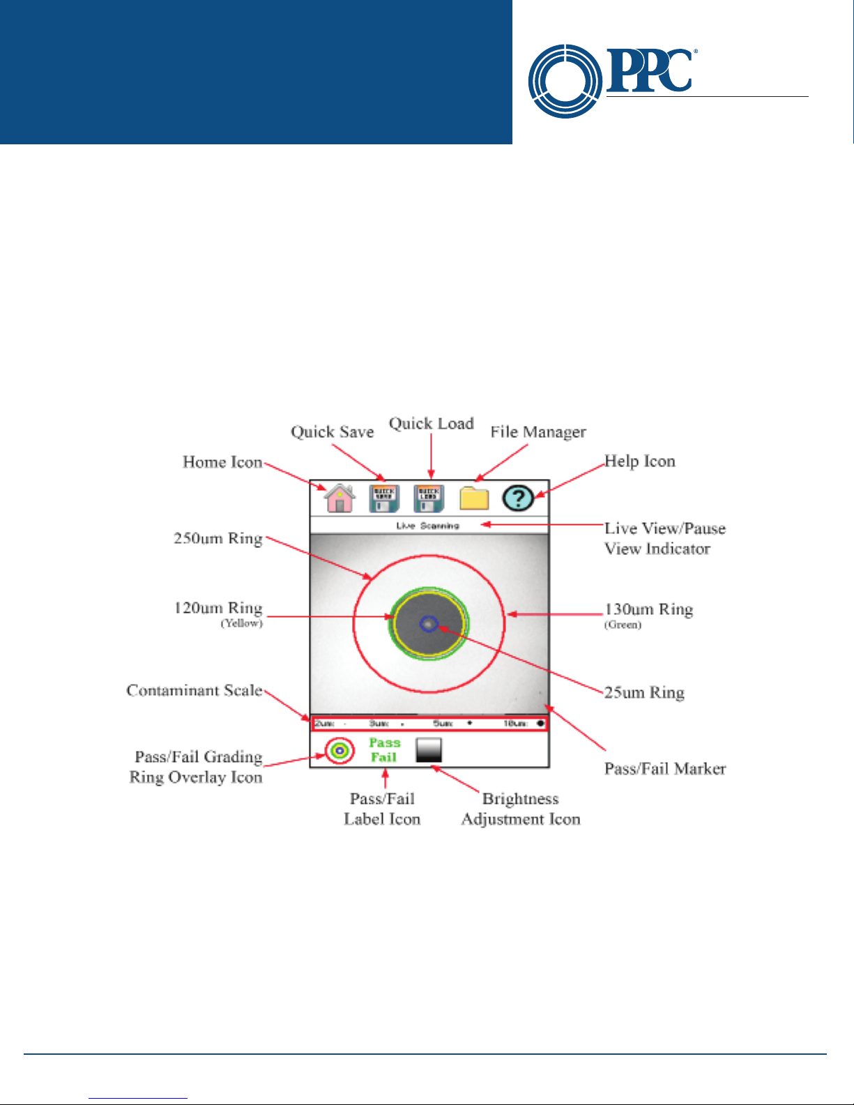
The icons at the top of the display are Home, Quick Save, Quick Load, File Management and Help.
Home
Press the Menu button, use the left and right buttons to highlight the Home icon and press Select or touch the
Home icon on the touchscreen to return to the Home screen.
6176 E. Molloy Rd. East Syracuse, NY 13057 U.S.A. • [email protected] • 1-800-800-6652 • +1 315-431-7200 • www.ppc-online.com
Fig 11.1
19
Page 20

NT2-210018 Optical Spectrum
Optical Network
Solutions
Analyzer User Guide
Quick Save
Press the Menu button, use the left or right buttons to highlight the Quick Save icon and press the Select button or
touch the Quick Save icon to store a le image of the scope screen to the next location.
Quick Load
Press the Menu button, use the left or right buttons to highlight the Quick Load icon and press the Select or touch
the Quick Load icon on the touchscreen to load the next stored scope image.
File Management
To open File Management, press the menu button, use the left or right buttons to highlight the File Management
(Folder) icon and press the Select button or touch the File Manager icon on the touchscreen. This will open the
Standard File Management screen as described in Section 10 of this user guide. Please refer to this section for
information on le processing.
Help
Press the Menu button, use the left and right buttons to highlight the Help icon and press Select or touch the Help
icon on the touchscreen to view the help information.
A BELDEN BRAND
11.3 Video Scope Operation Icon Menu
The following functions are only available for use when the video scope is in live scan mode. There are two modes
in the video scope: Menu mode and Live mode. The Menu button toggles between the two modes. Touching one of
the icons will also open the Menu mode. When in Menu mode, there will be a highlight around one of the icons on
the top or the bottom of the display.
Note
Touching icons on the video scope screen will put the unit into Menu mode and activate or toggle the
function. To exit Menu mode, it is necessary to use the Menu button on the keypad.
Grading Rings Icon
Used to turn on and o the rings that indicate the IEC61300-3-35 grading zones.
By entering the Menu mode with the Menu button, use the LRUD buttons to highlight the pass/fail grading rings
overlay icon and press the Select button or touch the icon. Exit the Menu mode and use the LRUD buttons to center
the image in the rings. Use the appropriate table from Section 11.5 to grade the connector end face. 2, 3, 5 and 10
micron contaminant examples are displayed just below the connect image on the Video Scope display.
Pass/Fail Label Icon
Used to cycle through pass, fail or no grading (o) of the pass/fail indicator. To set the pass/fail indicator, press the
Menu button, use the left or right buttons to highlight the pass/fail icon and press Select to cycle through the pass/
fail states, or touch the icon.
Brightness Icon
Press the Menu button, use the left and right buttons to highlight the Brightness icon, or touch the Brightness icon
to allow adjustment to the brightness level. Use the up and down buttons to adjust the brightness level of the
display or cycle through the brightness levels by pressing the Select button.
11.4 Video Scope Operation
To operate the video scope, bring up the Icon menu, highlight the Scope icon and press Select, or touch the Scope
icon on the touchscreen. If a probe is not connected already, connect the VIS300 Video Probe to the video probe
port on the top of the unit.
6176 E. Molloy Rd. East Syracuse, NY 13057 U.S.A. • [email protected] • 1-800-800-6652 • +1 315-431-7200 • www.ppc-online.com
20
Page 21
NT2-210018 Optical Spectrum
Optical Network
Solutions
Analyzer User Guide
Video Probe Tips
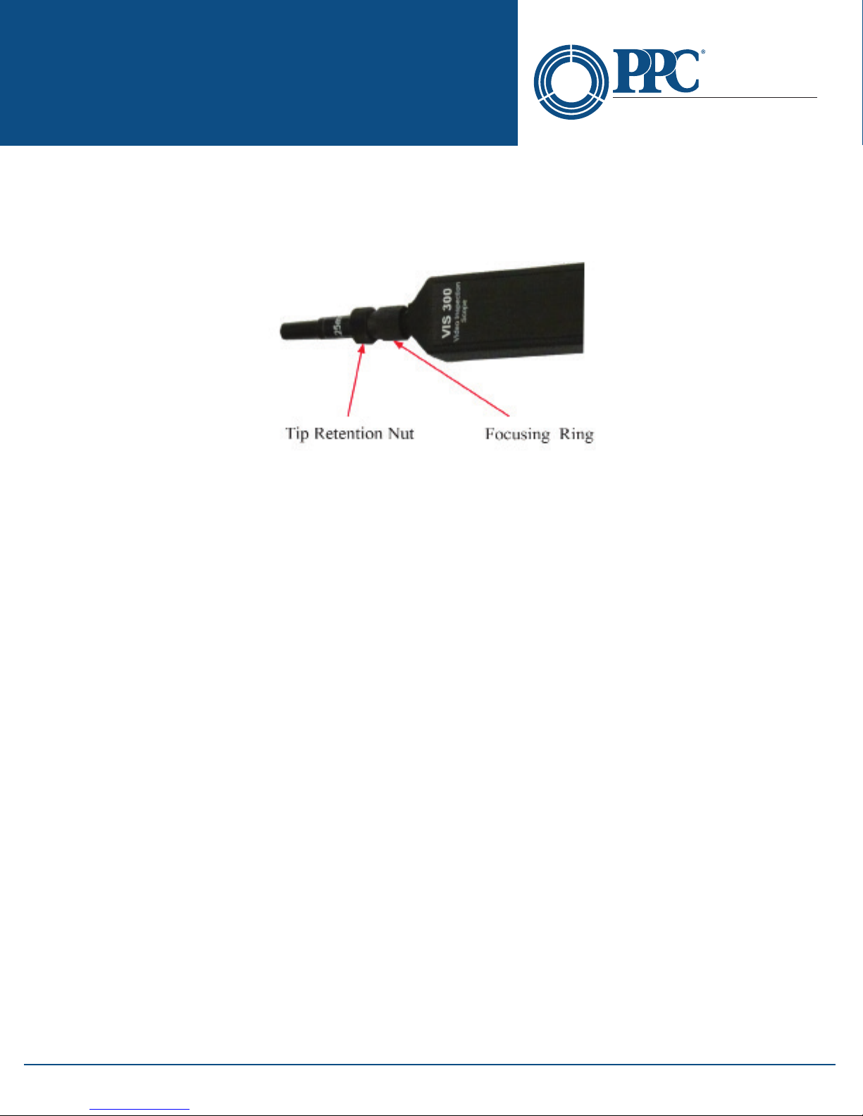
There are a number of Video Probe tips available. To remove a tip from the probe, grasp the focusing ring, back the tip
retention nut down and pull the tip straight up from the probe. To place a tip on the probe, ensure the lens is clean,
slide the tip on to the end of the probe and tighten the tip retention nut. Do not overtighten the retention nut.
Fig 11.2
Viewing/Focusing a Connector
With the video scope turned on and the video probe plugged into the unit, insert a connector into the universal tip
or insert the panel adapter tip into the appropriate port. Use the focus ring to get the connector image as sharp
as possible.
A BELDEN BRAND
Note
To make position adjustments with the LRUD buttons, the unit must NOT be in Menu mode. Menu mode is
evident when there is a light blue box positioned around one of the icons. When the touchscreen is used to
roughly center the connector image, the Menu mode is automatically turned o.
Centering a Connector Image
Once the image is stable and focused, use the stylus to touch the approximate center of the connector to snap the
image near the center of the display and the center of the grading rings. Use the LRUD buttons to ne tune the
image to the center of the display.
Pausing Image Scan
To freeze an image in position and focus level for inspection, press the Scan button. This will pause the image at the
current position and focus level. Simply press the Scan button again to set the operational mode back to live mode
for focus and position adjustments
Grading Rings
Turn on or o the grading rings by pressing Menu and using the left or right buttons to highlight the Grading Ring
icon and press Select or touch the icon on the touchscreen to toggle the rings on and o.
Pass/Fail
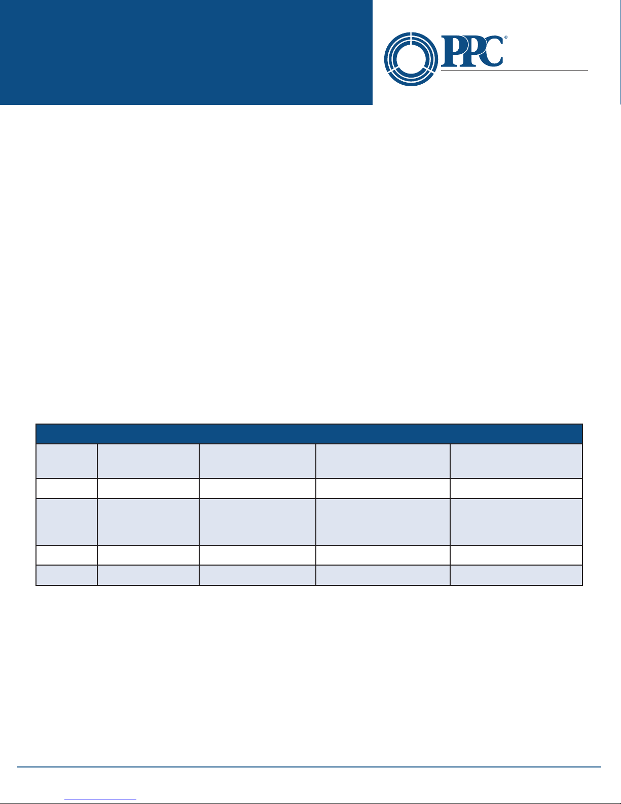
Using the pass/fail criteria tables on the next page, determine if the connector passes the IEC61300-3-35 standard.
There is a guide to contamination size located at the bottom of the image. To mark a connector as Pass or Fail, enter
the Menu mode, highlight the Pass/Fail Label icon and press Select to cycle through pass, fail, or no grading. The
touchscreen may also be used to cycle through these settings. Once the pass/fail status has be marked, the scan
may be paused with the Scan button and the points of contamination that caused a failure may be marked on the
image.
6176 E. Molloy Rd. East Syracuse, NY 13057 U.S.A. • [email protected] • 1-800-800-6652 • +1 315-431-7200 • www.ppc-online.com
21
Page 22
NT2-210018 Optical Spectrum
Optical Network
Solutions
Analyzer User Guide
Marking Points of Contamination
To mark the points of contamination, the unit must be in paused mode. Pick up the contamination marker by using
the stylus and touching the contamination sample size that is required. Touch the image to place the marker. The
marker may be ne tuned with the stylus to cover the contamination point on the image to be marked. Once the
marker is positioned properly, touch the area just below the image that states, "Place marker, touch here to apply"
to lock the marker in place. Repeat this as necessary to mark all the points that need to be indicated for the pass/fail
status. At this point, the image should be saved with the Quick Save icon to record the information.
Note
Marking the points of contamination should be done last, just before saving the image. Once the unit is returned to live mode, the markers are removed.
Exiting Video Scope Operation
Enter the Menu mode, use the left or right buttons to highlight the Home icon and press Select or touch the Home
icon directly on the touchscreen.
Note
The majority of functions and features in the Video Scope are operable with the touchscreen. It is not
necessary to enter the Menu mode when using the touchscreen. The Menu mode needs to be entered
when the focus of the LRUD buttons needs to be taken o the positioning feature and moved to the
icon cursor.
A BELDEN BRAND
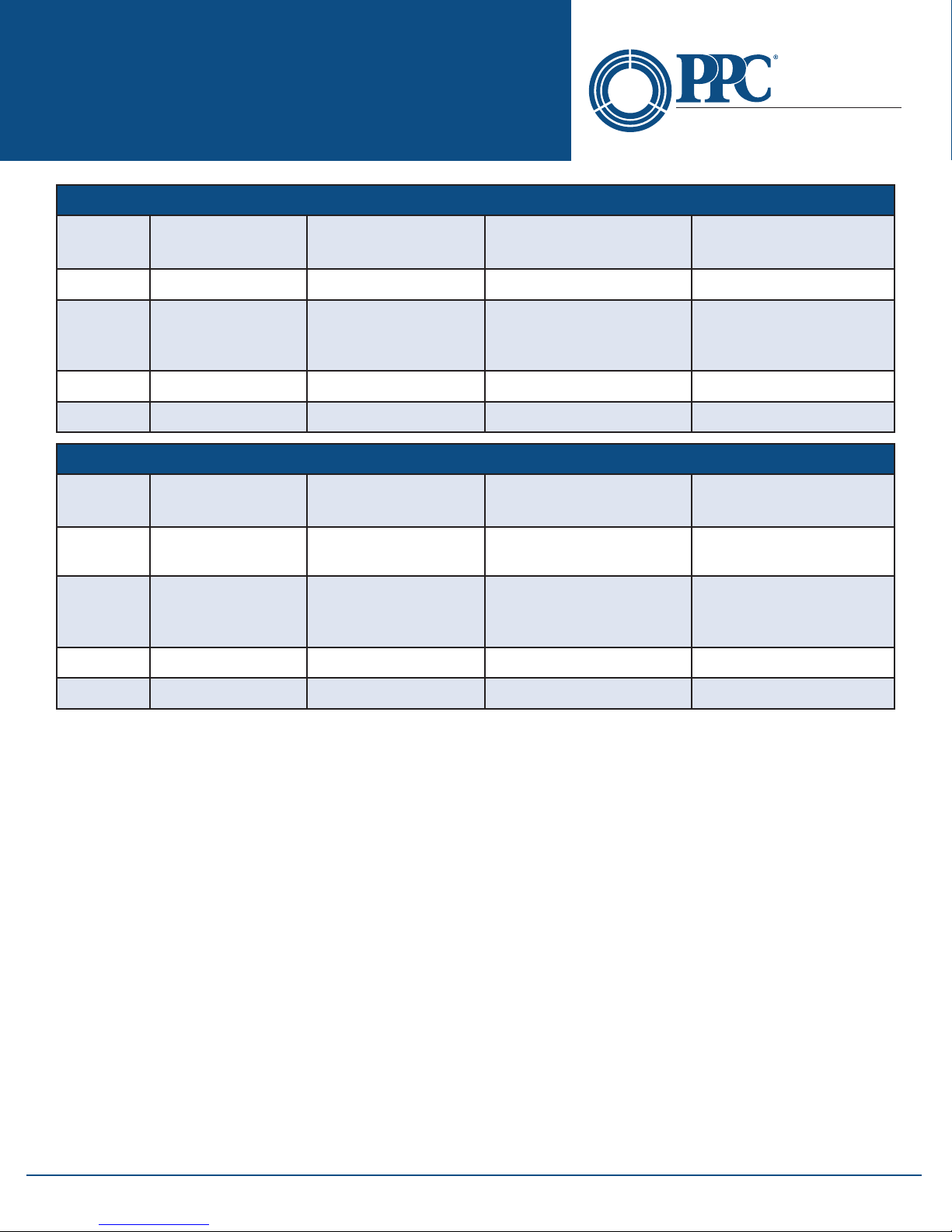
11.5 Pass/Fail Criteria Tables
Fiber End Face Criteria Table for Angled PC Polished Connectors
Zone Description Diameter
A Critical Zone 0μm to 25μm ≤ 4μm None
B Cladding Zone 25μm to 120μm No limit
C Adhesive Zone 120μm to 130μm No limit No limit
D Contact Zone 130μm to 250μm No limit None ≥ 10 μm
Allowable Scratches
(Width)
Allowable Defects
(Diameter)
No limit < 2μm
5 from 2μm to 5μm
None > 5μm
6176 E. Molloy Rd. East Syracuse, NY 13057 U.S.A. • [email protected] • 1-800-800-6652 • +1 315-431-7200 • www.ppc-online.com
22
Page 23
NT2-210018 Optical Spectrum
Optical Network
Solutions
Analyzer User Guide
Fiber End Face Criteria Table for Ultra PC Polished Connectors
Zone Description Diameter
A Critical Zone 0μm to 25μm None None
B Cladding Zone 25μm to 120μm
C Adhesive Zone 120μm to 130μm No limit No limit
D Contact Zone 130μm to 250μm No limit None ≥ 10 μm
Fiber End Face Criteria Table for SM PC Polished Conn. (Single Mode Fiber, RL≥ 26 dB)
Zone Description Diameter
A Critical Zone 0μm to 25μm
B Cladding Zone 25μm to 120μm
Allowable Scratches
(Width)
No limit ≤ 3μm
None > 3μm
Allowable Scratches
(Width)
2 ≤ 3μm
None > 3μm
No limit ≤ 3μm
None > 3μm
A BELDEN BRAND
Allowable Defects
(Diameter)
No limit < 2μm
5 from 2μm to 5μm
None > 5μm
Allowable Defects
(Diameter)
2 ≤ 3μm
None > 3μm
No limit < 2μm
5 from 2μm to 5μm
None > 5μm
C Adhesive Zone 120μm to 130μm No limit No limit
D Contact Zone 130μm to 250μm No limit None ≥ 10 μm
Section 12 - Maintenance
12.1 Battery Replacement
To replace the batteries, remove the OSA from the protective boot by pulling the bottom of the boot down and
back allowing the bottom of the unit to be lifted out. The battery door is located on the back side of the unit.
Replace the batteries with only high quality AA NiMH batteries. Spare battery packs are available with a charging
unit for extended battery operation. If you install NiMH batteries that are dead or less than 1 volt each, charge these
batteries for one hour before using the OSA. For proper maintenance, batteries require a monthly recharge.
Warning
To Prevent Fire or Shock Hazard:
• Do not install battery types other than those specied by the manufacturer
• Do not use the charger without the batteries installed
• Do not expose the battery charger to rain or excessive moisture
• Do not use the AC adapter when there are signs of damage to the enclosure or cord
• Ensure you are using the correct charger for the local line voltage
• Do not use any other charger than the one provided with this instrument
• Failure to follow these caution statements may void the warranty of this equipment
Note
For maintenance, batteries require a monthly recharge.
6176 E. Molloy Rd. East Syracuse, NY 13057 U.S.A. • [email protected] • 1-800-800-6652 • +1 315-431-7200 • www.ppc-online.com
23
Page 24
NT2-210018 Optical Spectrum
Optical Network
Solutions
Analyzer User Guide
12.2 Calibration and Verication
Periodic verication of the NT2-210018 is recommended to ensure your instrument remains within specication.
Although not imperative, we recommend a calibration and verication once a year to make certain the instrument
is functioning properly and performing to its rated specications. Consult the factory for service.
12.3 NT2-210018 Adapter Replacement
The NT2-210018 is supplied with two easily interchangeable adapters per port, SC/FC. To change an adapter,
remove the two screws that hold the adapter in place, pull the adapter straight up from ferrule. It is suggested you
clean the exposed ferrule with appropriate cleanser and a lint-free wipe any time you replace the ferrule.
Note
In order to maintain a low loss ber connection, care should be taken to adequately clean the ferrule of any
connector to be connected to the OSA. In the event that the port needs to be cleaned, the rst step is to be
certain the instrument is o. We suggest the use of isopropyl alcohol and foam swabs specically designed
for cleaning connectors accepting 2.5mm ferrules.
When replacing the adapter with one that does not have a chained protective cap, use the small screw in
place of the larger screw that retains the end of the chain to the adapter base.
A BELDEN BRAND
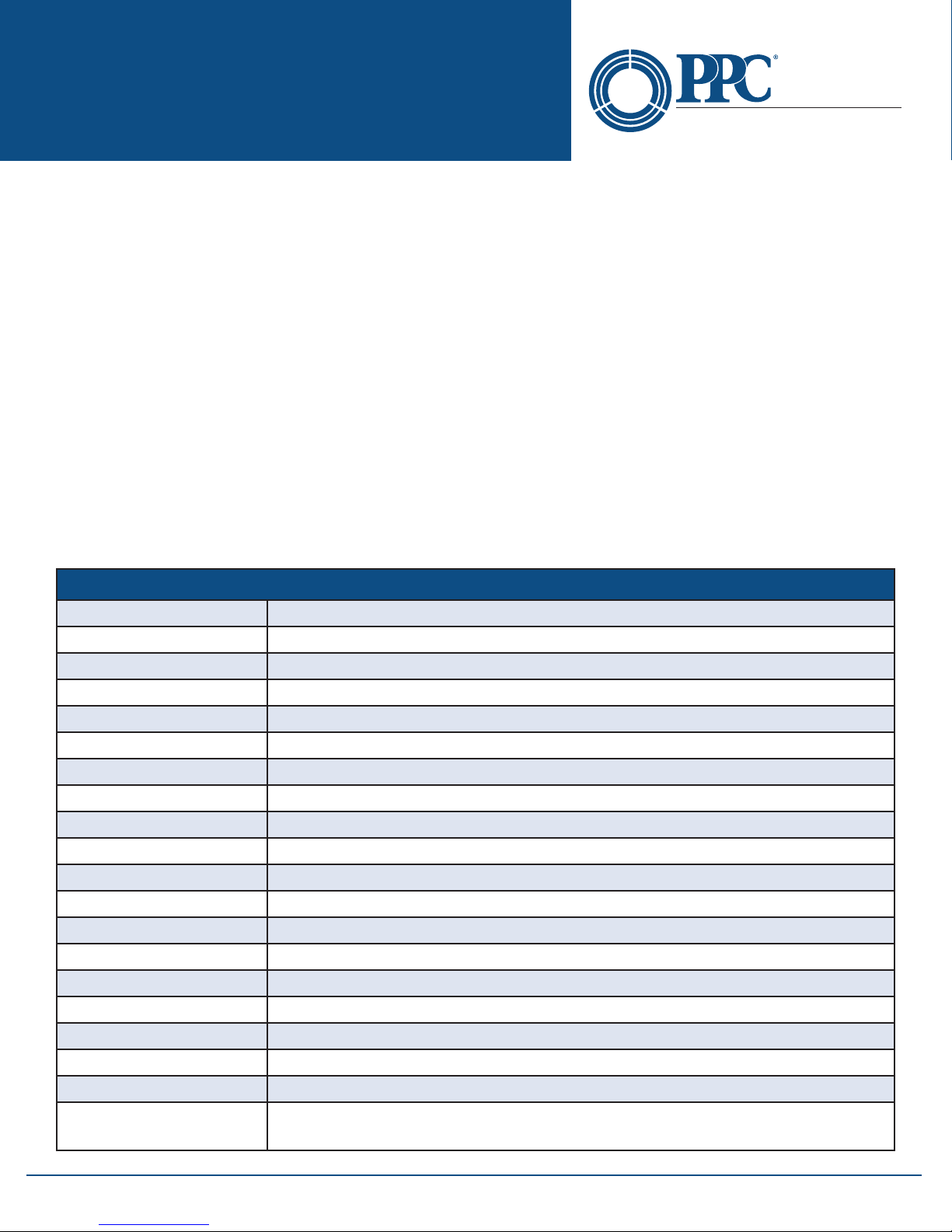
Section 13 - Specications
NT2-210018 Specications
Wavelength Range C-Band 1530 -1561nm (196.0 THz - 192.0THz)
Channel Spacing 50GHz, 100GHz
Wavelength Accuracy ±0.1nm
Channel Power Range +10dBm to -50dBm
Absolute Accuracy ±1 dB
Max Composite Power +28 dBm
PDL ±0.15dB
Optical Rejection Ratio 40dBc (@50GHz)
Measurement Time < 1/2 Second
Readout Resolution 0.01dB
Return Loss > 40dB
Optical Interface Universal UPC (FC/SC)
Graphical Display Bar graph and table view
Display 4 in. Touch color TFT
Dimensions 7.62” L x 3.88” W x 1.56” H (194mm L x 99mm W x 40mm H)
Weight 1.6 lbs
Battery Rechargeable NiMH - 4 hours operating time
Power 100-240 universal US, GB, EU, AU Mains
Environmental Operation -10°C to 50°C
Accessories Included
Specications are subject to change without notice
6176 E. Molloy Rd. East Syracuse, NY 13057 U.S.A. • [email protected] • 1-800-800-6652 • +1 315-431-7200 • www.ppc-online.com
Universal power supply with mains for US, UK, CE and AU. Interchangeable FC and
SC adapters, CertSoft Software Suite,USB cable, manual on CD and rubber boot
24
Page 25
NT2-210018 Optical Spectrum
Optical Network
Solutions
Analyzer User Guide
A BELDEN BRAND
Section 14 - Warranty and Repair
14.1 Warranty Information
This product, including all mechanical, electrical, and optical parts and assemblies, are unconditionally warranted
to be free of defects in workmanship and material for a period of one year from the date of delivery.
This warranty does not apply to expendable parts such as batteries or optical panel connectors, nor to any
instrument or component which has been subjected to misuse, alteration, or ber connector damage. It is the
customer’s responsibility to understand all the instructions and specications prior to operating this instrument.
This warranty does not extend to any loss or damage consequent to the failure of the warranted product.
14.2 Repair Information
If repair is required, simply call the factory for return instructions and a return authorization number (RMA).
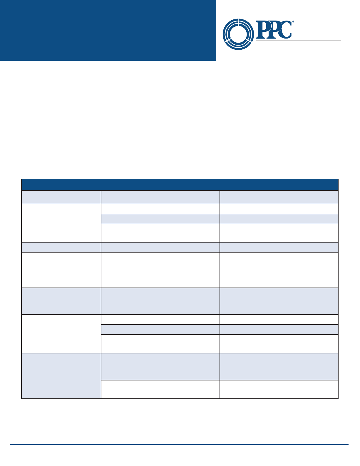
Section 15 - Trouble Shooting Guide
NT2-210018 Troubleshooting
Symptom Possible Cause Solution
Power not on Press ON/OFF key
LCD dark
LCD white Power cycled too quickly Turn o wait 10 seconds – turn on
Instrument locked Up Unexpected Operational Mode
Activity indicator does
not change to standby
or active mode
Low or no power being
displayed
USB hookup to PC not
functioning properly
Batteries require recharging Recharge batteries
Batteries are missing, in backwards
or need replacement
Power cycled too quickly Turn o wait 10 seconds – turn on
Defective cord or dirty connector Replace or clean cord
Fiber Output port requires cleaning Clean and inspect port
Angle polish mated with UPC polish
USB baud rate not set properly or too
quick for computer
PC drivers not set properly
Check polarity, replace batteries,
or contact factory for servicing
Turn o (hold ON/OFF button in for
1 second) wait 10 seconds – then
depress On/O again button to turn
the unit on
Examine connector ends for damage.
Use UPC Connectors ONLY!
Set port baud rate properly or
decrease Baud rate in instrument
and certication software
Un-install & re-install certication
software and drivers
6176 E. Molloy Rd. East Syracuse, NY 13057 U.S.A. • [email protected] • 1-800-800-6652 • +1 315-431-7200 • www.ppc-online.com
25
Page 26

NT2-210018 Optical Spectrum
Optical Network
Solutions
Analyzer User Guide
A BELDEN BRAND
Section 16 - Version Control
Through a program of continuous improvement, we upgrade the features and performance of the instrument in an
ongoing process. The instrument rmware version is accessible at “turn-on” on the bottom right-hand corner of the
display. The version changes and approximate release dates are as follows:
NT2-210018
V1.0.0.1 – 7/2014 - Original release - Requires version 1.0 software
6176 E. Molloy Rd. East Syracuse, NY 13057 U.S.A. • [email protected] • 1-800-800-6652 • +1 315-431-7200 • www.ppc-online.com
26
 Loading...