

PPA POTENZA PREDIAL SP, POTENZA PREDIAL JET FLEX, POTENZA PREDIAL Technical Manual
WARNING:
Do not operate the equipment without rst reading
the instruction manual.
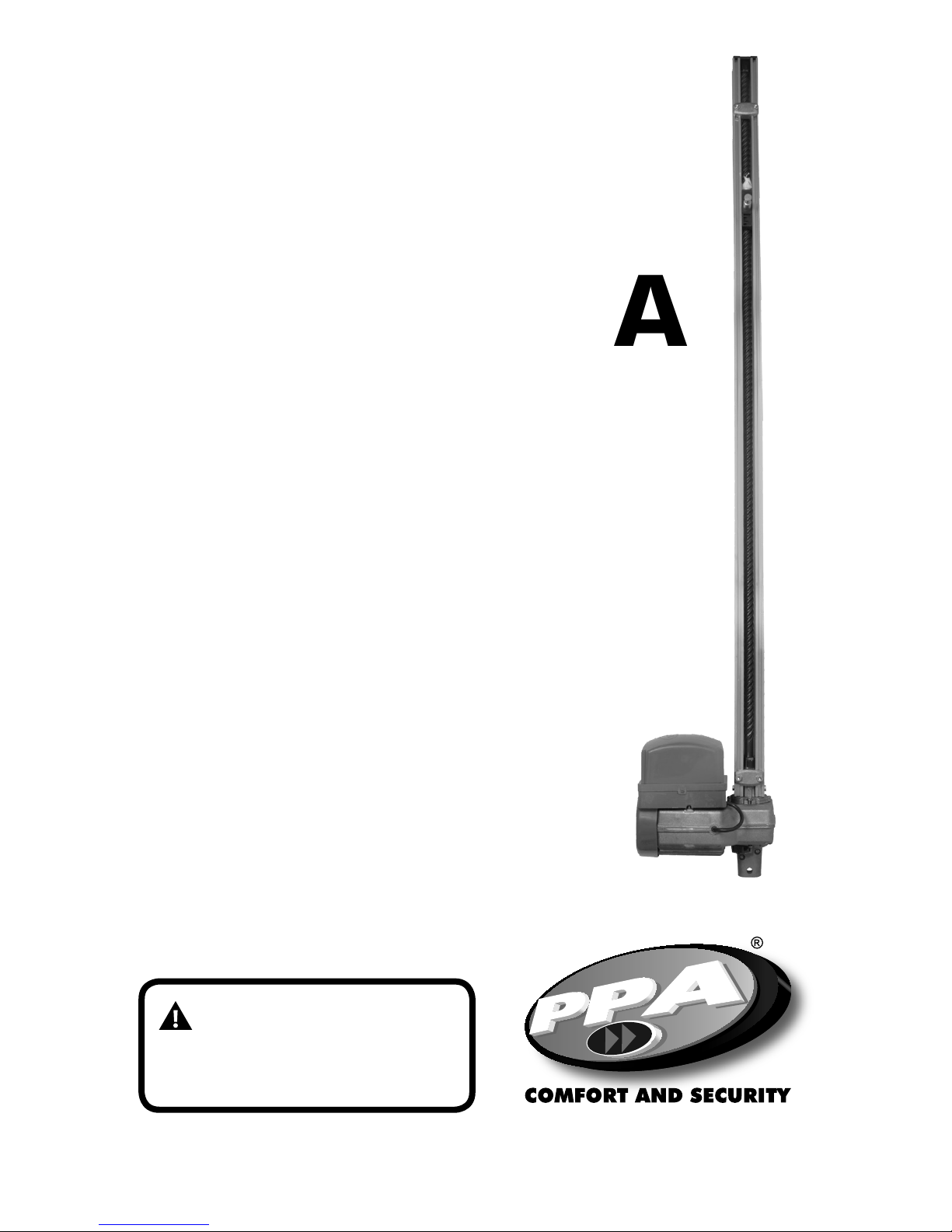
Technical Manual
POTENZA
PREDIAL
BV

2
INDEX
IMPORTANT SECURITY INSTRUCTIONS ................................................................................... 3
TECHNICAL CHARACTERISTICS .................................................................................................. 4
TOOLS REQUIRED FOR INSTALLATION ..................................................................................... 5
ELECTRICAL INSTALLATION ....................................................................................................... 5
PRECAUTIONS WITH THE GATE BEFORE INSTALLATION ................................................7
FIXATION AND INSTALLATION OF THE OPERATOR .............................................................. 7
ANALOGIC LIMIT SWITCH INSTALLATION .............................................................................11
MAINTENANCE ...............................................................................................................................13
3
IMPORTANT SECURITY INSTRUCTIONS
Recommendation:
For the installation of the equipment, it is
important that a PPA specialist installer
follow all instructions given in this technical
manual and in the user manual.
With the user’s manual, the installer must
present all the information, uses and safety
items of the equipment to the user.
Before using the automation, read and
follow all instructions contained in this manual carefully.
-Before installing the operator, make sure
that the local power supply is compatible
with that required on the equipment identication label;
- Do not connect the electrical grid until installation / maintenance is complete. Always
make electrical connections to the control
unit with the electrical grid switched o;
-After installation, make sure that the parts
of the gate do not extend through the roads and public walk;
-It is mandatory to use full shutdown devices in the automation system
4
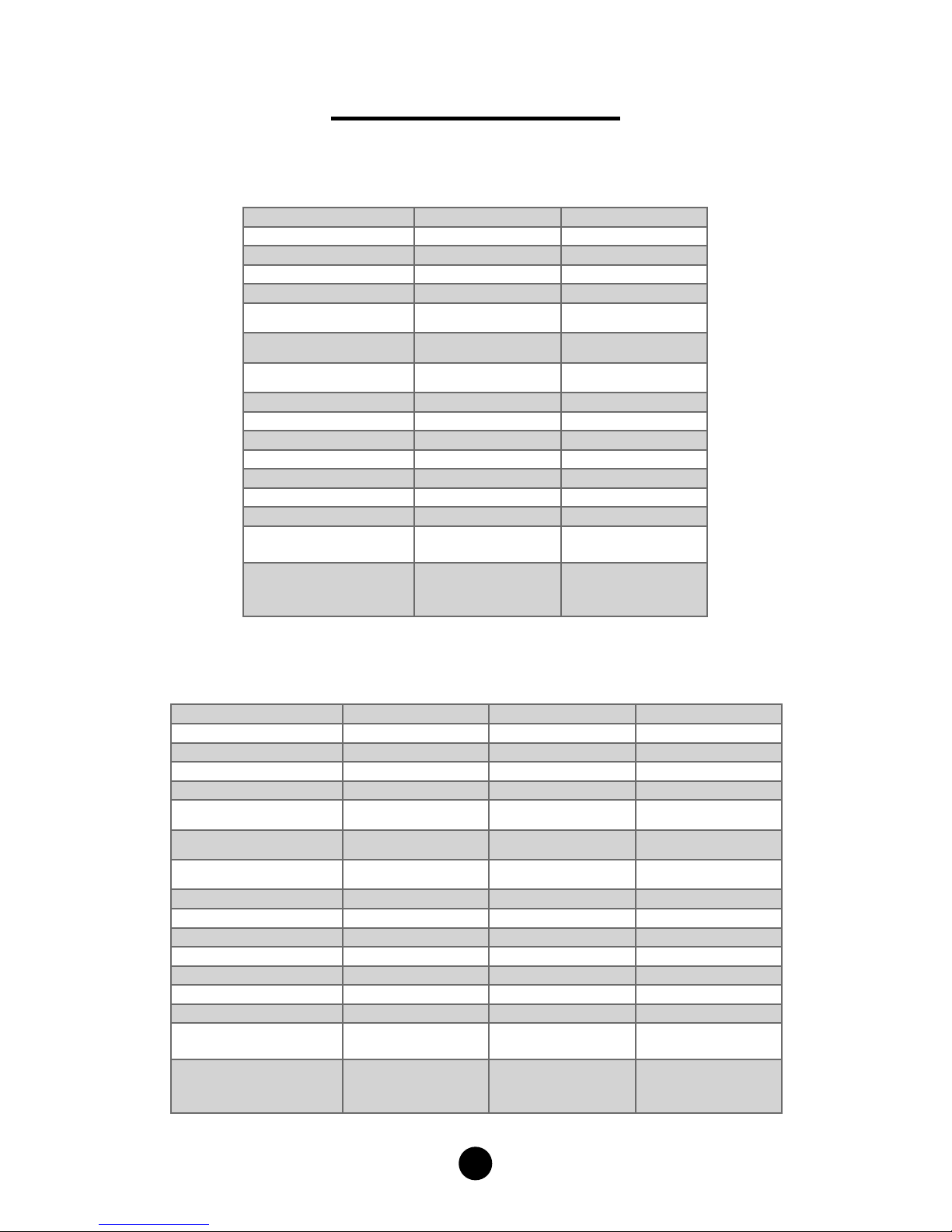
TECHNICAL CHARACTERISTICS
* Maximum height is calculated by the value obtained in the product description (value in meters) applied in the equation.
POTENZA PREDIAL
POTENZA PREDIAL SP / POTENZA PREDIAL JET FLEX
OPERATOR TYPE OVERHEAD OVERHEAD
MODEL Single Phase Single Phase
RATED VOLTAGE 220 V 127 V
NOMINAL FREQUENCY 60 Hz 60 Hz
NOMINAL POWER 540 W 390 W
RPM 1740 RPM 1740 RPM
NOMINAL CURRENT 2,5 A 3,7 A
REDUCTION 2:30 2:30
LINEAR SPEED 7 m/min 7 m/min
MANEUVER 50 cycles/h 50 cycles/h
PROTECTION LEVEL IPX4 IPX4
RAIL Aluminum Aluminum
TEMPERATURE RANGE -5° C / +50° C -5° C / +50° C
ISOLATION TYPE Class B, 130° C Class B, 130° C
LIMIT SWITCH Analogic / Digital Analogic / Digital
MAX. WEIGHT OF
GATE LEAF
400 Kg 400 Kg
MAX. DIMENSION OF
THE GATE
*HEIGHT = (Value
in meters -0,15) x 2
LENGTH = 4,0 m
*HEIGHT = (Value in
meters -0,15) x 2
LENGTH = 4,0 m
OPERATOR TYPE OVERHEAD OVERHEAD OVERHEAD
MODEL Single Phase Single Phase Jet Flex
RATED VOLTAGE 220 V 127 V 220 V / 127 V
NOMINAL FREQUENCY 60 Hz 60 Hz 60 Hz
NOMINAL POWER 540 W 390 W 300 W
RPM 1740 RPM 1740 RPM 4365 RPM
NOMINAL CURRENT 2,5 A 3,7 A 2,2 A / 3,1 A
REDUCTION 2:30 2:30 2:30
LINEAR SPEED 7 m/min 7 m/min 17,4 m/min
MANEUVER 50 cycles/h 50 cycles/h 60 cycles/h
PROTECTION LEVEL IPX4 IPX4 IPX4
RAIL Aluminum Aluminum Aluminum
TEMPERATURE RANGE -5° C / +50° C -5° C / +50° C -5° C / +50° C
ISOLATION TYPE Class B, 130° C Class B, 130° C Class B, 130° C
LIMIT SWITCH Hybrid Hybrid Hybrid
MAX. WEIGHT OF
GATE LEAF
320 Kg 320 Kg 400 Kg
MAX. DIMENSION OF
THE GATE
*HEIGHT = (Value
in meters - 0,15) x 2
LENGTH = 4,0 m
*HEIGHT = Value in
meters - 0,15) x 2
LENGTH = 4,0 m
*HEIGHT = (Value
in meters - 0,15) x 2
LENGTH = 4,0 m
5
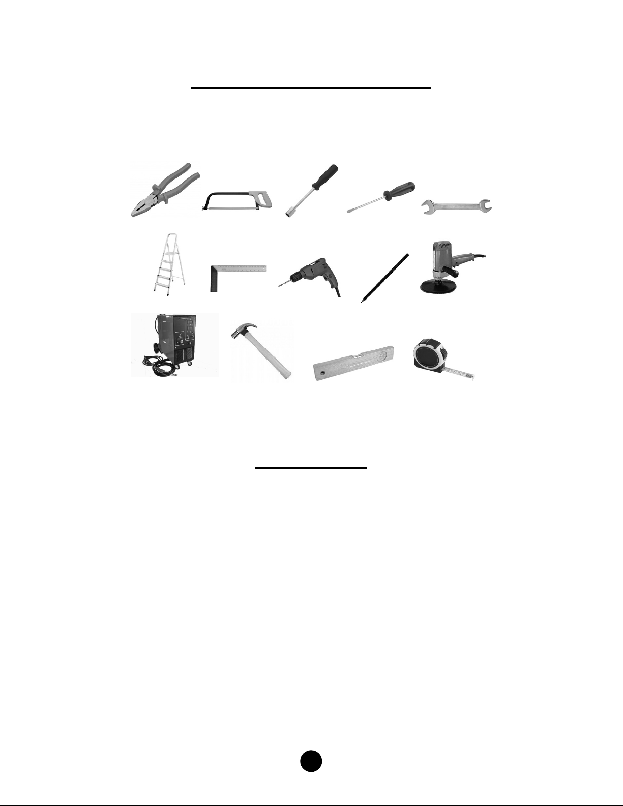
TOOLS REQUIRED FOR INSTALLATION
Here are some tools required to install the automation:
ELECTRICAL GRID
For electrical installation, the network shall contain the following characteristics:
- Electric network 127 V or 220 V;
- Have 5 A circuit breakers in the electrical distribution box;
- 3/4 “diameter conduit between the electrical distribution box and the total
disconnect device;
- 3/4 “diameter conduit between the total shut-o device and the automator’s
connection point;
- 1/2 “diameter conduits for external and optional push button;
- Theres of 1/2 “diameter for safety photocells (optional).
PLIERS HACKSAW NUT DRIVER SCREWDRIVER WRENCH
LADDER
WELDING MACHINE HAMMER LEVEL MEASURING TAPE
SQUARE DRILLER PENCIL SANDER
 Loading...