


2 3
IMPORTANT SAFETY INSTRUCTIONS
Recommendation:
For the installation of the equipment, it is important that the specialized installer follow all instructions given in this TECHNICAL MANUAL
and USER MANUAL.
With the USER MANUAL, the installer must provide all the information, and uses the user equipment safety items.
Before using the GIRO SOCIAL DOOR OPERATOR, read and follow
all instructions contained in this manual carefully.
- Before installing the operator system, make sure that the local electrical network is compatible with the one required on the equipment
identification label. Connect the power cord only into outlets connected to the ground network;
- Do not connect the mains until installation / maintenance is complete. Make the electrical connections of the board always turning off
the electrical network;
- After installation, make sure that the door parts do not extend
through the roads and public walkway;
- Under no circumstances, remove the grounding pin from the power
plug. Do not use adapters that eliminate this ground connection. It is
mandatory to use the ground pin.
INDEX
Important Safety Instructions ...............................................................................................3
Tools needed for installation .................................................................................................4
Electrical installation .............................................................................................................4
Care with electrical installation .............................................................................................5
Technical characteristics ......................................................................................................6
Installing and fixing the operator ..........................................................................................7
Arm fixing ..................................................................................................................7
Fixing the operator to the wall ...................................................................................7
Fixing the guide to the door ......................................................................................9
Radar ........................................................................................................................9
Photocell .................................................................................................................13
Closing the operator cover .....................................................................................14
Maintenance .......................................................................................................................15
Defects, Probable causes, and Corrections ...........................................................15
Inverter command to the board ..........................................................................................16
Board inverter installation .......................................................................................16
First drive of the inverter after being installed on the door
automatic (memorization) .......................................................................................16
From the second drive on .......................................................................................17
Quick guide for programming the frequency inverter.............................................17
Photocell incorporated ............................................................................................21
Encoder Test ...........................................................................................................21
STS Jumper .............................................................................................................22
Event and fault signaling .........................................................................................22
Decimal point functions of the inverter displays when the
Operator is operating ..............................................................................................22
Possible errors and defects ....................................................................................23
4 5
TOOLS NEEDED FOR INSTALLATION
Here are some tools needed to install the operator:
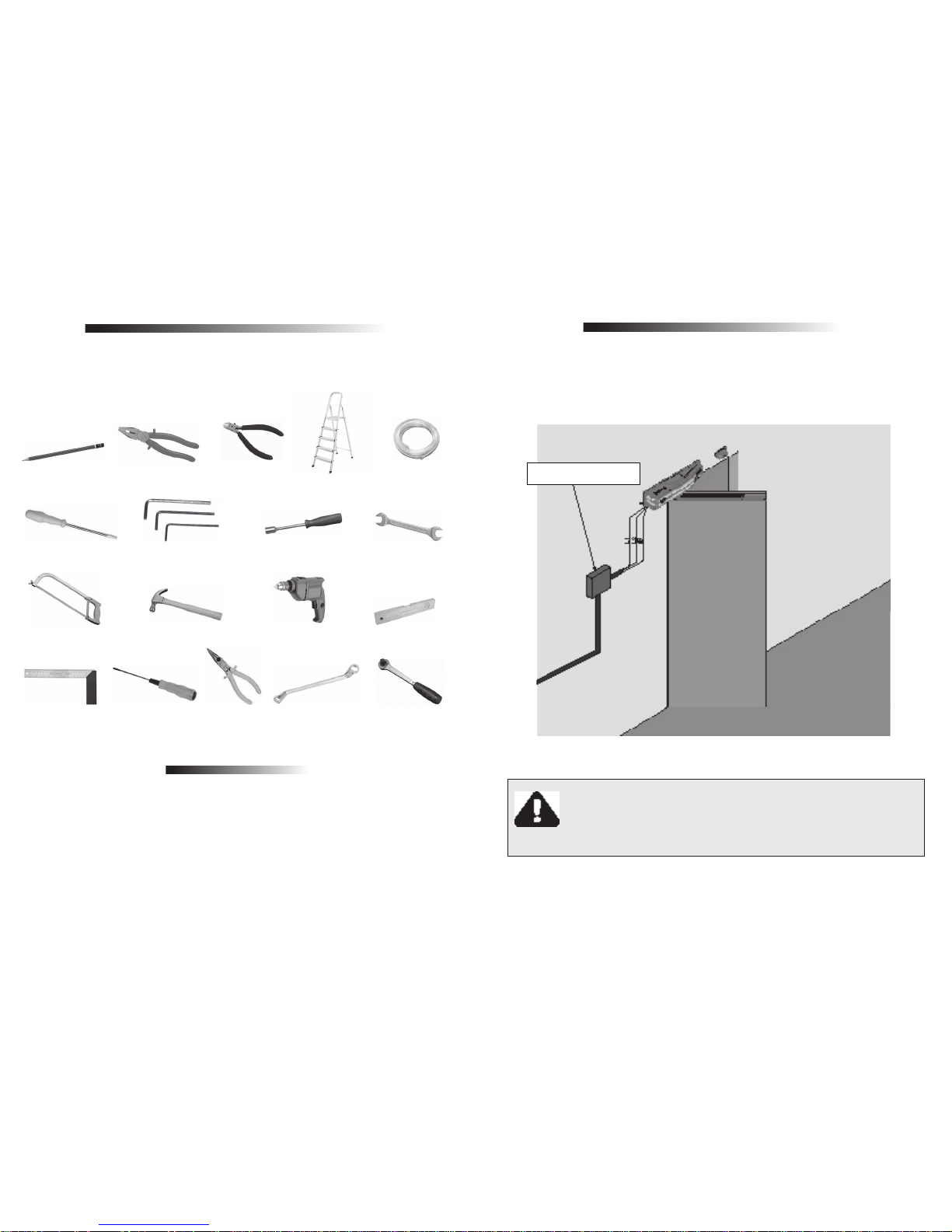
ELECTRICAL INSTALLATION
For electrical installation, the network shall contain the following characteristics:
- Electric network 127V or 220V;
- Have 5A circuit breakers in the electrical distribution box;
- 3/4 "diameter conduit between the electrical distribution box and the total disconnect device;
- 3/4 "diameter conduit between the total turn off device and the operator connection point;
- Conduits 1/2 "in diameter and optional external buttonhole;
- 1/2 "diameter conduit for safety photocells (required).
PENCIL
SCREWDRIVER
SAWING BOW
FRAME
UNIVERSAL
PLIERS
ALLEN KEY
3, 4 e 6mm
HAMMER
PHILIPS KEY
CUTTING
PLIERS
HAMMER
SOCKET WRENCH
10mm
DRILL
SCREWDRIVE STAR
NEEDLE-
NOSED PLIERS
NUT WRENCH 10,
13, 22 e 28mm
COMMON LEVEL
HOSE LEVEL
LADDER
RATCHET SCREWDRIVER
CARE WITH THE ELECTRICAL INSTALLATION
To avoid damage to the wiring, it is important that all conductors be properly fixed
to the operator. Wiring must be done through conduits, passing internally through
the base of the floor, ensuring that none of the wiring conductors are trapped and
damaged.
IMPORTANT
The device must be powered by a residual current (DR) device with a
rated residual current of more than 30 mA
.
TURN OFF MEANS
6 7
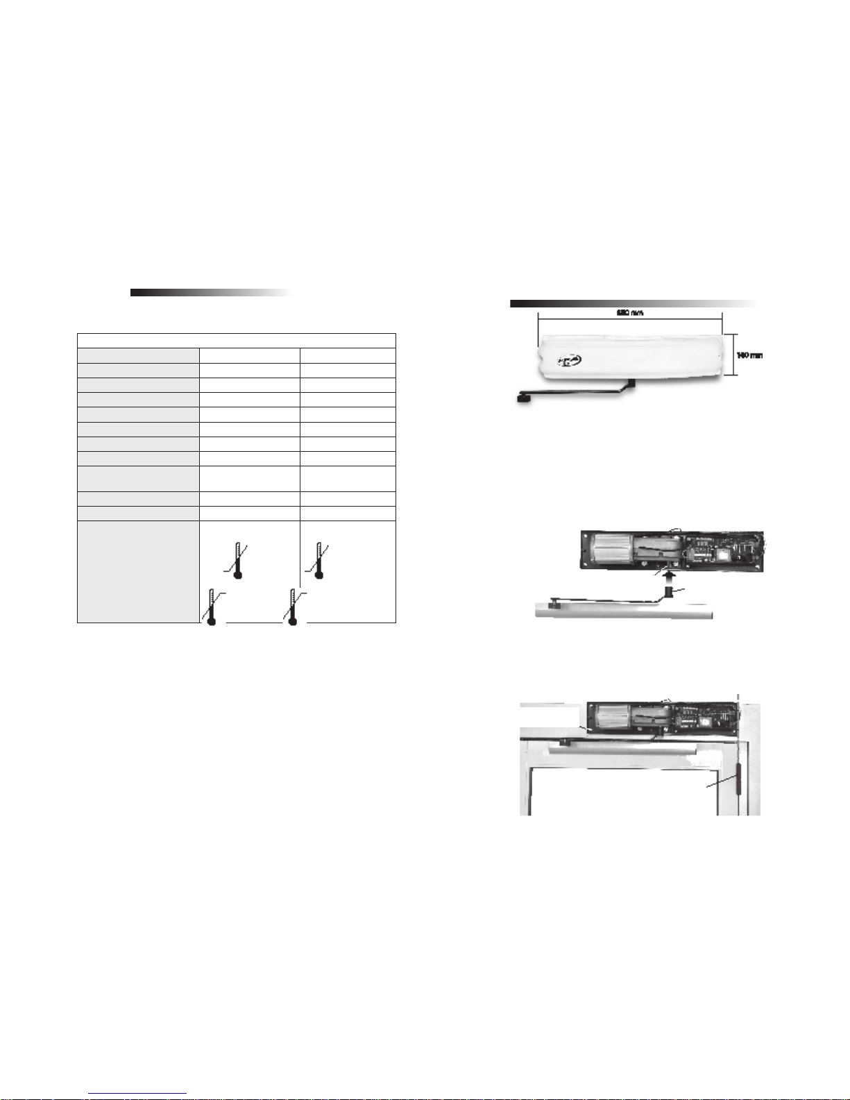
INSTALLING AND FIXING THE OPERATOR
ARM FIXING
Fixed the articulated arm to the gear motor shaft and, using an Allen wrench, secure with the screw that comes with the kit.
FIXING THE OPERATOR TO THE WALL
Secure the operator so that the steel base is aligned with the door hinge.
PARAMETER AND TECHNICAL CHARACTERISTICS
OPERATOR TYPE PIVOTING PIVOTING
RATED VOLTAGE 220 V 220 V
NOMINAL FREQUENCY 60 Hz 50 Hz
RATED POWER 150 W 150 W
MOTOR ROTATION 3492 rpm 2910 rpm
NOMINAL CHAIN 1,2 A 1,2 A
REDUCTION 1:111,5 1:111,5
LINEAR SPEED 1,2 m/minute 1,2 m/minute
OPERATIONS 240 Continuous cycles 240 Continuous
cycles
DEGREE OF PROTECTION IPX 0 IPX 0
RAIL Aluminum Aluminum
TEMPERATURE RANGE
-5°C
+50 °C
-5°C
+50 °C
GEARMOTOR SHAFT
TECHNICAL CHARACTERISTICS
ARTICULATED ARM
ALIGNED
FIXING SCREW
ARTICULATED ARM

8 9
If the door is an internal opening, secure the operator so that the drive arm is
slightly above the top of the door leaf.
If the door is an external opening, secure the operator so that the drive arm is
below the top of the door leaf.
FIXING THE GUIDE TO THE DOOR
After fixing the operator to the drive arm, secure the aluminum guide to the door so
that the drive arm does not extend beyond the limit and do not move off the guide
(fixe the aluminum guide in the center of the door).
NOTE: Check manually whether the door opens and closes properly without friction.
RADAR
Radar is a sensor that drives the automatic door when an object approaches its
detection radius.
Technical specifications
- Supply voltage: 12 to 24 VDC / 12 to 18 VAC
- Voltage and current in the relay contacts: 200 V / 0.5 A
- Frequency emitted: 24,125 GHz
- Maximum installation height: approximately 3.5 m
- Adjustment angles: 0 to 90º vertical and -45 to 45º horizontal
THE DRIVE ARM MUST BE
ABOVE THE TOP OF THE LEAF.
ALUMINUM GUIDE
THE DRIVE ARM MUST BE BELOW
THE TOP OF THE LEAF.

10 11
- Detection area: - long - narrow
Knowing the board
Installation mode
1. Fix the radar in the desired place and connect the power cord (red and brown
are power supply and yellow and orange are the contacts of the relay).
2. Adjust the sensitivity through the P1 trimpot.
3. Adjust the direction of the detection area through the mechanical positioning of
the antenna. For wide detection area, install the antenna upright (connector up).
For narrow detection area, install the antenna in the horizontal position (connector
to the right).
Connector up = long detection Connector to the right = narrow detectio
NOTE
To reverse the position of the antenna, push
the locks in opposite direction from each other,
remove the board and fit it back into the desired
position (figure on the side). Pay attention to the
correct position of the connector. The side with
the arrow should always be facing the outside of
the board (figure on the side).
Dip switch setting
Key 1 sets the state of the relay: ON = NF and OFF = NA.
Key 2 sets the pulse time retention shot: ON = 2 seconds and OFF = 0,5 seconds.
Key 3 sets the mode of immunity: ON = high immunity and OFF = normal immunity.
NOTE
Set up with high immunity in environments where rain or other light movement may
occur in front of the sensor to prevent false shots. This setting makes the sensor
"slower".
Observations:
- Do not touch the surface area of the antenna, as it is sensitive to small electrostatic
discharges.
- Do not install the sensor in places where plant movements or other objects may
occur.
- Do not install the sensor near fluorescent bulbs as they may cause interference.
- Do not install in places where vibration may occur.
- Ensure good sensor fixing to prevent false shots.
Dip Switch setting /
Trimpot P1 for sen-
sitivity adjustment
/ In this connector,
the side with the arrow should face up.
/ Detection Antenna.
Antenna locking
latches
This side out

12 13
Wiring diagram in the Command Board - Radar
PHOTOCELL
Fixing and connecting the photocell
1. Pass a 4-way cable going from the TX to the board, passing through the rail and
fastened with cable ties.
2. Pass a 4-way cable going from RX to the board, passing through the rail and
fastened with cable ties.
The command for the activation of the photocell must be made by an NF (Normally
Closed) contact, that is, for the board to receive a photocell command, the
connection between PHOTO and GND of the CN6 connector.
Precautions
-Do not install the receiver directly facing the sun;
- Make sure that the side that has the output of the wires is positioned downwards;
Fixing the radar on the cover
Fit and fix the radar stand near the Giro operator.
PHOTO / RADAR / EXTERNAL RADAR / INTERNAL RADAR /
Internal (polarized) connector / Gray Cable
RADAR

14 15
Photocell connection
CLOSING THE OPERATOR COVER
After all connections and adjustments have been made, fit the board cover,
close the operator cover and fixed it with 2 screws M5 x 10 .
MAINTENANCE
Before any Maintenance, remove the power cord from the electrical
network.
DEFECTS, POSSIBLE CAUSES AND CORRECTIONS
It will mention some DEFECTS, PROBABLE CAUSES AND CORRECTIONS, which
may occur in your operator, in case you need to occur Maintenance.
INVERTER COMMAND TO THE BOARD
DEFECTS PROVáVEIS CAUSAS CORREçõES
Door opening and closing
alone
-Dirt in the rail.
-Dirt in the door guide.
-Radar unregulated, is
picking up the movement
of the leaf.
-Clean the rail.
-Clean the door guide.
--Regular sensitivity of the
radar.
Door slowly opening - Lack of electricity.
--Drive the radar on and
wait for the door to open
and close slowly.
Door opened and did not
close
Blocked photocell. -Unblocked the photocell.
TRANSMITTER
PHOTOCELL
RECEIVING
PHOTOCELL
SCREW M5 X 10

16 17
INVERTER BOARD INSTALLATION
The electrical connections of the board must be made according to the diagram
contained in this manual.
When the automatic door has an electromagnetic lock, or garage light, a relay
module must be connected to "LOCK" and / or "LIGHT" (optional, separate sale).
To adapt a single receiver, simply connect it to "RECEIVER" (optional). The motor
is connected to the "MOTOR" terminal.
The mains voltage is connected to the "NETWORK" terminal and must be either
127Vac or 220Vac according to the "CH1" voltage selection switch and the
frequency according to the requested transformer in the inverter (60Hz or 50Hz).
The CN4 has a 15V (450mA) power supply to power the radars and the photocell
as well as the input for radar command and photocell command. The radar
command is a normally open contact, that is, for the board to receive a command,
you must connect RADAR1 or RADAR2 to the GND.
The photocell PHOTO command on the CN4 connector must be a normally closed
command, that is, for the board to receive a photocell command, the PHOTO of
the GND must be disconnected.
FIRST DRIVE OF THE INVERTER AFTER BEING INSTALLED ON THE
AUTOMATIC DOOR (MEMORIZATION)
WARNING: Before any drive, make sure that the door model selected in the
inverting unit is the same port that is installed (F9 function, see Table 2).
The photocell PHOTO command on the CN4 connector must be a normally closed
command, ie for the board to receive a photocell command; the PHOTO of the
GND must be disconnected. If no photocell is used, a jumper between PHOTO
and GND must be connected. (Optional / replacement).
After the inverter is energized for the first time, start the motor by pressing the OK
button or by a command on RADAR1 or RADAR2 or RECEIVER. The door should
initiate an opening movement, for better visualization of the movement leave it in
the middle of the opening path. If the door starts a closing movement, remove the
F / R jumper, wait two seconds (2s), and then start the engine again. Note that the
board will change the direction of the motor. The door should start the opening
movement.
After this condition, leave the door open until it stops at the opening stop. Then it
will reverse the direction to close, let it lean against the closing stop. The automatic
door is now ready to operate.
Note: During closing in the storage period, only one photocell command can
revert the door.
FROM THE SECOND DRIVE ON
After memorizing, the door need not record the route again. On a new power-up,
it will simply open slowly until it stops at the opening stop. Ready! The door is now
ready to operate.
QUICK GUIDE FOR FREQUENCY INVERTER PROGRAMMING
The inverter already comes with factory-set parameters, but the user can modify
them if he deems it necessary. To do this, press and hold the SHIFT key (+) until
the display shows F01, you can now release the key. Ready, the user has already
entered the programming mode. The programming menu has twenty-six functions
(26) functions described in the table below:
CODE
PRINTED
ON
DISPLAY
FUNCTION
F01 Semi-automatic mode or pause time in automatic mode.
F02 Operation with lock or without lock.
F03 Time the garage light stays on after the door is closed.
F04 Reset recorded route.
F05 Opening speed.
F06 Closing speed.
F07 Opening limit switch.

18 19
CODE
PRINTED
ON DISPLAY
FUNCTION
F08 Closing limit switch.
F09 Door model (Bona, Flash, Tore, Avanti, Replacement and Pivoting).
F10 Sensibility of anti-smashing at closing (force at closing).
F11 Enables or disables Anti Panic.
F12 Function to choose whether the door should stop when there is na anti panic signal
or if should open at a slower speed.
F13 Filter time for photocell command input and “Radar 1”.
F14 Limit switch speed.
F15 Applies the factory settings.
F16 Deceleration at closing.
F17 Reserved.
F18 Anti panic opening speed.
F19 Forçe during opening.
F20 Closing limit switch force (closing ensure).
F21 Enables or disables “Anti-wind” function (more used in the pivoting model).
F22 Acceleration / deceleration at opening.
F23 On/Off Pulse on the closing lock.
F24 Enable inver ted pause.
F25 Wait time to start the engine after the lock has been activated.
F26 On/Off automatic opening when the door is manually moved in the opening
direction
Out Exit the programming menu.
To navigate through the programming menu, simply press the SHIFT (+) button
to incremented or (-) button to decrease until find the desired function, and then
press OK to enter the function. Each function has own specific settings that can
be changed by the SHIFT (+) button or (-) button.
When finish changing, press OK again and then the value is saved and the menu
returns to the functions and can navigate through again.
See the table below for the meaning of each existing configuration for the functions.
FUNCTION
EXISTING CONFIGURATION
FOR THIS FUNCTION
MEANING OF CONFIGURATION
F01 Sau/t00 to t99
Semi-automatic mode (SA) or pause time in seconds
[s].
F02 tof or t01 to t99
Disables the operation of electromagnetic lock (tof) or
enable locking and the activation time of it (t01 to t99)
in milliseconds, t01 = 0,1s.
F03 t00 to t99
Time the garage light comes on after the door is
closed (time in seconds [s]).
F04 rst or nrt Delete the route (rst) or do not delete the route (nrt).
F05
001 to 060 for Tore and
Replacement models, up to
090 for the Flash and Bona
models.
Opening speed, 001 to 090 [Hz].
F06 001 to 090 Closing speed 001 to 090 [Hz].
F07 001 to 099
Openign limit switch, 001 (minor), 099 (higher limit
switch).
F08 001 to 099
Closing limit switch, 01 (minor), 99 (higher limit
switch).
F09
FLA, bon, tor, rEP, AuA or PIu
Door model: Flash (FLA: larger motor with encoder
hall), Bona (bon: smaller motor with encoder
hall), Tore (tor: smaller motor with hall encoder),
Replacement (rEP: smaller motor with optical
encoder), Avanti AuA: medium motor with Hall
encoder) and Pivot (PIu).
F10 A10 to A50
Sensitivity of the anti-smash in the closing, the smaller
the value, the smaller the force. Higher the value, the
greater the force.
F11 dAP or EAP
Enable (EAP) or disable (dAP) anti-panic.
ATTENTION: This function should only be enabled if
the door is the mechanical anti panic system.
F12
oPE to Sto
Set the anti-panic function to open the door (ope)
or stop the door (sto) when receiving an anti-panic
signal.
F13
t01 or t99
Waiting time to recognize that there is no photocell
command and "radar 1", this function is used when
the door is commanded by access control by cards,
time x 100ms (one hundred milliseconds) [ms].
F14 001 to 015 Limit switch speed [Hz].
F15 ndE or dEF Applies factory values (dF) or does not apply (nd).
F16 001 or 099
Deceleration at closing [Hz / s], the lower the
smoother the motion and the greater the closing limit
switch.
F17 Reserved.

20 21
FUNCTION
EXISTING CONFIGURATION
FOR THIS FUNCTION
MEANING OF CONFIGURATION
F18 001 or 025
Opening speed [Hz] when there anti panic signal, if
the door is configured to open in this situation.
F19 10 to A50
Opening force. WARNING: If the value is too low, the
operator can have little force to open, slowing.
F20 000 or 015
Force in the final closing region, used to ensure
closing.
F21
dAu or LAu
Enables (dAu) or disables (LAu) anti-wind function.
This function is most commonly used in pivoting
doors, forming the set closing again if the door open
due to an external factor and not by an electric
command.
F22
001 to 099
Acceleration / Deceleration at aperture [Hz / s]. As
the value of this function decreases, the opening
movement of the door will be smoother and the open
limit switch should be increased as the door will
require more braking space
F23 dPt or LPt
Turn on closing lock pulse (LPt) or turn off closing
pulse lock (dPt).
F24
PnI or PIn
Non-inverted pause (PnI) starts counting when the
door is fully open. Pause inverted (PIn), the pause
starts counting when there is no more radar, photocell
or buttonhole signal. If any command is restarted
during the pause, the count is restarted.
F25 tof or t01 to t99
Disables the wait to start the engine after tof the tof
or enables the time to start the engine (t01 to t99) in
milliseconds, t01 = 0.1s.
F26 LAA or dAA
Turn on automatic open when the door is moved in
the open direction (LAA) or Turn off automatic when
the door is moved in the opening direction (dAA).
Out Exit of the menu. Exits the programming menu.
Important: At the end of the configuration of the operating parameters, navigate
the menu to the Out function and press OK. If the card is turned off without this
operation, the settings will return to the previous.
ATTENTION: It is mandatory (a) to use photocells to prevent accidents.
INCORPORATED PHOTOCELL
In this board there is a incorporated photocell, ie it is only necessary to connect
the light transmitter and the infrared light receiver to the "TXFOT" and "RXFOT"
connectors respectively.
Operation can be checked by the first display point from left to right. When the
point is lit, the photocell is obstructed. When the point is off, the light receiver is
receiving the signal from the light transmitter.
When the photocell is disconnected or has any change of connection or operation,
the door remains open until the correction is applied.
ENCODER TEST
It is possible to test the encoder operator by simply plugging it into the board
and starting the motor, press the SHIFT button once and the display will show the
encoder pulses in real time. There is a sequence of pulses that must be obeyed:
First sequence: the display shows 0 1 3 2 ...
Second sequence: the display shows 0 2 3 1 ...
Any sequence is valid, but if the encoder is working correctly all numbers should
appear, without exception!
Pressing the SHIFT button a second time, the route of the door will be shown in
hexadecimal format, eg the number 0200h corresponds to the zero point (door
open).
Ao pressionar o botão SHIFT pela segunda vez, o percurso da porta será mostrado
no formato hexadecimal, exemplo: o número 0200h corresponde ao ponto zero
(porta aberta).
ATTENTION: To check that the motor encoder is in perfect condition, open and
close the door several times by pressing the OK or RADAR button, then open it
and leave it open, then press the SHIFT button twice and write down the number
(it should be 0200h). Whenever the door is open, the display should mark the
position 0200h or close to it, for example: 0201h or 0202h. If the number changes
beyond 0200h, the encoder may be experiencing problems.
When you press the SHIFT button for the third time, the bus capacitor voltage will
be displayed (V).
After the button is pressed, the display will automatically delete in 255s.

22 23
TST JUMPER
When removing the TST jumper, the OK button is used to slowly rotate the motor
in a certain direction while the button is pressed, and the SHIFT button is used to
turn the motor in the opposite direction of the OK button while it is pressed. When
the TST jumper is replaced, the inverter returns to normal operation.
EVENTS AND FAULTS SIGNING
The main function of the OSC LED is to indicate that the microcontroller of the
board is operational (the same flashes, with fixed frequency (~ 1Hz), as long as
the power is on).
The BUS LED indicates that there is load on the capacitors of the DC bus.
ATTENTION: Do not touch the power region (capacitor region) of the board while
this LED is lit even after the inverter is disconnected from the electrical network!
The FAULT LED indicates the alignment between the emitter and the receiver of
the internal photocell. The higher the light intensity of the LED, the greater the
alignment accuracy of the TX / RX photocell.
The activated panic indication (unlocked ports) is signaled on the seven segment
displays (DSP1, DSP2 and DSP3) by means of the "APA" description (display
format source).
NOTE: The signaling connections of the activated panic system are carried out by
means of the ANTPA and ANTPB connectors.
FUNCTIONS OF THE DECIMAL POINTS OF THE INVERTER
DISPLACES WHEN THE OPERATOR IS OPERATING
There are some functions for the decimal points of the displays when the operator is
operating, these functions facilitate the verification of the operation and installation
errors:
1. The point of the unit (the first point from the right to the left) represents commands
for opening, ie when there is a receiver command or buttonhole, the point will be
lit. When there is no signal, the point remains off.
2. The point of the tenth (the second point from the right to the left) represents a
photocell signal, if the photo is drive or absent or still faulted the point will be lit and
the door will remain open.
3. The hundredth point (the third point from right to left) represents whether there
is a signal from the incorporated photocell. Lit point: photocell blocked, missing or
connection failure; the door will remain open until clearing / correction.
POSSIBLE ERRORS AND DEFECTS
Errors
1.E00, E01 and E02: Signals that the power part of the inverter is faulty. Cause:
Problems with power or weld defect. Solution: A qualified technician should
evaluate the equipment.
2. E03: There is no encoder signal. Cause: Encoder disconnected or defective.
Solution: Connect encoder to the board and check encoder.
3. E04: Indicates that the route recorded during memorization is too small. Cause:
The encoder cable is missing and the door is locked. Solution: Check the encoder
cable, check if the door slides all the way, in case the error persists.
4. E06: The port is not reaching the zero point (aperture). Cause: Encoder may be
broken, or lack of force at the end of stroke. Solution: Check the encoder. Increase
the limit switch speed (see "Encoder Test").
5. E09: Possibility of loss of synchronism of the belt with the toothed pulley. Cause:
Belt loose or improper to pulley.
ATTENTION: When the new inverter is to replace one of the old model (optical
encoder), the two wires in the middle of the encoder harness must be crossed:
- Old sequence: Black, White, Red, Yellow.
- New sequence: Black, Red, White, Yellow.
- For the optical encoder extender that has two ends, cross only one of them:
- Old sequence: Brown, Red, Orange, Yellow.
- Sequence and mapping are as follows: Brown, Orange, Red, Yellow.

24 25
DEFECT
DEFECT CAUSE SOLCTION
The door does not
match the installed
location route (brakes
before closing stop or
hits closing).
There is a different route
recorded the route from
the local installed.
Enter the function menu
and function 4 (F4),
change from nrt to rSt,
exit the menu via out,
and allow to memorize
the course.
Door remains open
and when it receives
commands to open, it
closes.
The memorization was
performed erroneously.
See item: First drive of
the inverter after being
installed in the operator
(memorization).
 Loading...