

PPA FACILITY CONNECT Technical Manual
NOTE: If is a Digital limit switch System, after
programming the “Default Settings” topic, it is
necessary to memorize the route. Otherwise, the
board will operate with a minimum of 100 pulses.
IMPORTANT
• Once the board has been installed in the operator
system, it is necessary to memorize the path for
correct operation.
• In case of limit switch, whenever the power is
switched on (first command after power failure),
the motor will be activated (pulsing torque
mode) until the mechanical closing stop is found.
If this is done, the operation will be normal.
• In case of limit switch, whenever it is necessary to
reverse the motor rotation (black and red wires),
the boardmust be switched off. After the first
command after reconnecting it, the operating
procedure will be identical to the previous topic.
It is not necessary to reverse the position of the
encoder because the board corrects the position
automatically. Reversing the direction of rotation
of the motor is necessary to adjust the operation
of the board to the position of the gate. Failure
to observe this item may result in improper
operation of the operator by reversing the logic
operating for controls and photocell.
• In case of limit switch, when storing the course or
near the limit switch, the engine will be running
in pulsating torque mode, ie the engine will be
on and off continuously.
• The maximum pause time is 4 minutes.
• In case of limit switch, in equipment with little
force to learn the course, we must abort the
process and enter the programming to increase
the pulsating torque force in the memorization
(simultaneously press the 2 buttons of the
transmitter for 8 Times).
• To perform any of the programming steps on the
board, there is no need to record the 2 buttons
on the transmitter. With just one of the recorded
keys, we can access all the functions of the
electronics.
• When the PROG jumper is open, the GRV button
functions as the gate open / close command.
3. TRANSMITTER RECORD
The board can record up to 160 different and
independent buttons.
For transmitter record:
1. The gate must be stopped and not be timed for for
automatic closing.
1. Close the jumper PROG. The green SN led must be
dim.
2. Press and hold the transmitter button. The green SN
led should flash.
3. Press and release the GRV button, and check the
SN led:
- If the SN led flashes 1 time: Recorded the
transmitter button.
- If the SN led flashes 2 times: The transmitter
button is already recorded.
- If the SN led flashes 3 times: The memory
is full.
4. Release transmitter button.
5. To record other transmitter buttons, continue from
step 3.
6. To end the operation, open the jumper PROG.
NOTE: In User Mode (open PROG jumper), the
transmitter commands are only for gate opening /
closing operation. In this mode, the control panel
will not accept a command when the 2 transmitter
buttons are pressed simultaneously.
4. SELECTING DIGITAL OR ANALOGUE COURSE
SYSTEM
1. The gate must be stopped and not timed for
automatic closing.
2. Manage the PROG jumper open.
3. Select the limit switch option via the FC jumper:
FC Open: Limit switch Analog.
FC Closed: Limit switch Digital.
4. After selecting the limit switch system, it will be
necessary to memorize the automatic route.
Otherwise, if Digital limit switchis selected, the
board will operate with a minimum of 100 pulses
or, if Analog limit switch is selected, the opening /
closing time will be 120 sec.
5. AUTOMATIC BOARD PROGRAMMING
(COMPLETE CYCLE)
1. The gate must be open.
2. Close the PROG jumper. The green SN led must be on.
3. Simultaneously press and release the 2 transmitter
buttons (recorded) once. The SN led will flash when
the buttons are released. After 5 seconds, the board
will enter the automatic programming mode.
4. The gate will close until the mechanical stop FCF
(Closing limit switch) or the two buttons of the
transmitter are pressed simultaneously. After 1
second, the gate will open by memorizing the route
until you find the mechanical stop FCA (Opening
limit switch) or if the two buttons on the transmitter
are pressed simultaneously.
NOTE: In the case of Digital limit switch, in the
course of Memorizing the engine will operate in
Pulsating Torque mode.
5. The SN led will begin to flash as a clock every
1 second and wait for the programming of the
Automatic or Semi-Automatic Mode.
NOTE: If both buttons of the transmitter are
pressed simultaneously, the Pause setting will be
canceled and you will go to the next step, leaving
the last setting recorded.
Automatic Mode: In this mode, after it is
opened, the gate will close automatically after a
programmed pause time.
When the SN led:
• Slow flashing 1 time (2 sec.): Force minimum.
• Fast flashing: Strength adjustment between the
minimum and maximum.
• Slow flashing 1 time (2 sec.): Maximum force.
To go back and select new setting (step 6):
Simultaneously press and release the 2 buttons on the
transmitter.
To end programming: Simultaneously press and
release the 2 transmitter buttons or open the PROG
jumper.
9.ADJUSTING THE OPENING/ CLOSING
POSITION OF THE LIMIT SWITCH
This type of adjustment allows you to gradually
advance or rewind the limit switch, independent of
the opening and closing stop.
1. The gate must be stopped and not timed for
automatic closing.
2. Selected Digital limit switch (FC jumper closed).
3. The gate path must be memorized. Otherwise, the
function will be canceled.
4. Close the PROG jumper. The green SN led must
be dim.
5. Simultaneously press and release the 2 buttons
on the transmitter (recorded) 6 times. The SN
led will flash each time the buttons are released.
Waint 5 seconds.
6. Next, the SN led will go off and the board will wait
for the limit switch position programmed.
7. To adjust the position of the closing limit switch,
press and release the GVR button. The SN ledwill
flash once.
NOTE: If the REC button is not pressed, the
adjustment of the limit switch position will be
opening.
8. Adjusting the position of the limit switch (setting up
to 10 pulses)
1 pulse back off of the limit switch position:
Press the left button of the transmitter until find
the desired setting.
Advance 1 pulse of the limit switch position:
Pulse the right button on the transmitter until
find the desired setting.
To go back and select new setting (step 6):
Simultaneously press and release the 2 buttons on the
transmitter.
End programming: Simultaneously press and release
the 2 transmitter buttons or open the PROG jumper.
10.ADJUSTING THE OPENING/ CLOSING
INDEPENDENT LIMIT SWITCH
The limit switch is the distance that is missing to
reach the mechanical stop. The board will continuosly
monitor the position of the gate and when it reaches
this limit, the pulsating torque mode is turned on to
slow down and to smoothly stop. .
1. The gate must be stopped and not timed for
automatic closing.
2. Selected Digital limit switch (FC jumper closed).
3. The gate path must be memorized. Otherwise, the
function will be canceled.
4. Close the PROG jumper. The green SN led must be
dim.
5. Simultaneously press and release the 2 buttons on
the transmitter (recorded) 7 times. The SN led will
flash each time the buttons are released. Wait 5
seconds.
6. Next, the SN led will turn off and the board will wait
for the limit switch programmed.
7. Adjusting the limit and check the SN led. The
function has up to 5 adjustment levels:
8. To adjust the position of the closing limit switch,
press and release the GRV button. The SN led wil
flash once.
NOTE: If the GRV button is not pressed, the li mit
switch setting will be adjusted for the opening.
Decrease limit switch distance: Press the left button
of the transmitter until the desired setting is reached.
Increasing the limit switch distance: Press the right
button of the transmitter until you find the desired
setting.
End programming: Simultaneously press and release
the 2 transmitter buttons or open PROG jumper.
When the LED SN:
• SN led slow flashing 1 time (2 sec): minimum
limit.
• SN led flashes fast: between minimum and
maximum limit.
• SN ledflashes slow 1 time (2 sec): maximum limit.
Divider adjustment index (5 levels): 04, 08, 16, 32
and 64
Exemplo:
• Memorized course by the board = 1000 pulses.
• Limit switch selected = Divider 04.
• Calculation: 1000 pulses / 04 = 250 pulses remaining.
• Then, when 250 pulses are missing to reach the
mechanical stop, the board will reduce the speed
in pulsating torque so that the gate gently touches
the stop.
NOTE: The higher the divider, the lower the speed
reduction distance, the gate will be closer to the
mechanical stop of the limit switch.
11. AJUSTING OF THE TORQUE FORCE
PULSING INDEPENDENT FOR OPENING AND
CLOSING MEMORIZED OF THE COURSE.
To set the pause time, press and hold the right
button of the transmitter and count the seconds
through the clock or SN led. After counting
the pause time, the transmitter button must be
released.
Semi-Automatic Mode: In this mode, after
opening the gate, a new command is required
for closing.
To program, press and release the left button of
the transmitter.
6. The gate will start to cycle in a continuous close and
open and wait for the programming of the Motor
Force (Electronic Clutch). This force must be checked
by trying to hold the gate. To reduce or increase the
force exerted by the motor, proceed as follows:
Decrease Strength: Press and release the left
button of the transmitter and check the force
again. If necessary, you can press and release
the left button slowly until you find the desired
setting.
Increase Strength: Press and release the right
button of the transmitter and check the force
again. If necessary, you can press and release
the right button momentarily until you find the
desired setting.
NOTE: At this stage, the gate will not reach the
mechanical stop (opening / closing), but until the
point of the course where there will be the change
from high speed to low. This transition point is
programmable (see “Limit switch Adjustment”).
7. When the desired force is chosen, the 2
transmitter buttons must be pressed and released
simultaneously, and then the motor will be turned
off and the selected force will be recorded in the
memory.
NOTE: At this stage, if the PROG jumper is opened,
the motor will shut down and will not record the
force setting, keeping the previous record.
8. To complete the Automatic Programming (Full
Cycle), open the PROG jumper.
NOTE: Automatic Programming (Full Cycle) can be
terminated at any time in the plant configuration
cycle, just by opening the PROG jumper.
During the programming process, only the
transmitter recorded in memory and started
programming can interfere with or change
the configuration parameters. To change the
programming of the control panel with another
recorded transmitter, you must restart the entire
programming process.
6. AUTOMATIC PROGRAMMING OF BOARD
(FROM PAUSE ADJUSTMENT)
1. Close the PROG jumper. The green led SN should
be dim.
2. Simultaneously press and release the 2 buttons
on the transmitter (recorded) 2 times. The LED SN
flashes each time the buttons are released. After
5 seconds, the board will enter the automatic
programming mode (see from step 5 of the previous
topic - Automatic plant programming [full cycle]).
7. DELETE ALL THE TRANSMITTER MEMORY.
1. The gate must be stopped and not timed for
automatic closing.
2. Close the PROG jumper. The green led SN should
be dim.
3. Simultaneously press and release the two buttons
on the transmitter (recorded) 3 times. The SN led
will blink every time the buttons are released.
Wait 5 seconds.
4. Next, the SN led will be on awaiting confirmation
for the exclusion of the transmitters or the
cancellation of the operation.
To cancel operation: Press and release the left
button of the transmitter. The SN led will be
weak again.
Deleting all transmitters: Press and release the
right button on the transmitter. The SN led will
flash 3 times indicating that you have cleared all
transmitters.
5. Open the PROG jumper.
8. SETTING TORQUE FORCE PULSATING
INDEPENDENT FOR OPENING AND CLOSING
The board will be pulsing the motor, ie it will be turned
off and turned on quickly so that it has low speed force.
Depending on the weight of the gate, the torquemust
be adjusted to move it.
1. The gate must be stopped and not timed for
automatic closing.
2. Selected Digital limit switch (FC jumper closed).
3. The gate path must be memorized. Otherwise, the
function will be canceled.
4. Close the PROG jumper. The green SN led must
be dim.
5. Simultaneously press and release the 2 buttons
on the transmitter (recorded) 5 times. The SN led
will flash each time the buttons are released. Wait
5 second.
6. Next, the SN led will turn off and the board will
wait for the setting of the pulsating torque force
setting.
7. To adjust the pulsing torque fosse in the
clsingcycle, must press GRV.The SN led will flash
1 time.
NOTE: If the GRV button is not pressed, the force
setting of the pulsating torque will be for the
opening cycle.
8. Adjust the force and check the SN led. The function
has up to 32 adjustment levels:
Decrease the force of the pulsating torque:
Press the left button of the transmitter until the
desired setting is reached.
Increase the force of the pulsating torque:
Press the right button of the transmitter until
you find the desired setting.
IMPORTANT
Please read this manual carefully for proper use and
to ensure proper installation of the automation. All
data referenced in this manual is for information
only. Any technical changes to the product are
reserved without prior notice.
QUICK REFERENCE GUIDE TO
PROGRAMMING INDEXES
Simultaneously press the 2 buttons on the
transmitter (the number of times indicated below).
At least one of the buttons must be recorded:
1 time: Automatic board Programming (full cycle).
2 times: Automatic programming of the board
starting with the Pause setting.
3
times
: Deleting all transmitters from memory.
4 times: Factory default settings (Reset).
5 times: Adjusting the pulsating torque (opening /
closing).
6 times: Adjustment of the limit position (opening
/ closing).
7 times: Limit switch setting (opening / closing).
8 times: Setting the pulsating torque in the memory
(opening / closing).
9 times: Setting the brake operating time.
10 times: Select transmitter code type (fixed /
moving).
11 times: Select relay module type (latch, garage
or signal light).
1. MAIN CHARACTERISTICS
• Digital / Analog End-of-Course System.
• RF receiver module 433.92 MHz.
• Rolling Code up to 160 different and independent or
fixed code transmitters button rolling.
• Automatic memory of the course.
• Selecting the automatic or semiautomatic mode via
the transmitter.
• Setting the pause time for automatic closing via the
transmitter (maximum = 4.0 min).
• Adjusting the electronic clutch (force) through the
transmitter.
• Command to delete all transmitters through the
transmitter.
• Command to configure the board (factory default)
via the transmitter.
• Output for relay module, Garage Light, Signal or Lock.
• Input for external device selector as programmer or
bluetooth for access and also programmer.
• Photocell input.
• RF receiver socket.
• Pushbutton input.
• Input for external device selector as programmer or
bluetooth for access and also programmer.
2. DEFAULT SETTINGS (FACTORY DEFAULT)
• Strength = Maximum.
• Closing = Semiautomatic.
• Pulse torque (aperture) = Level 8.
• Pulsing torque (closing) = Level 5.
• Pulse force in the memorization (opening)= Level 11.
• Pulse torque in memory (closing) = Level 7.
• Limiter system = Depends on the FC jumper setting:
- If jumper FC open = Analog limit switch, then:
* Brake time (opening / closing) = 200 msec.
* Time A / F = 120sec.
- If jumper FC closed End of digital course, then:
*Brake time (open / close) = Off.
*Track = 0.
• Limit switch = Course / 16
• Retraction FCA = 2 pulses.
• Recall FCF = 0 pulses.
• Relay module output = Latch.
To return to the factory default settings:
1. The gate must be stopped and not be timed for
automatic closing.
2. In the FC jumper, select the limit switch: Analog (FC
open) or Digital (FC closed).
3. Close the PROG jumper. The green led SN should
be dimly lit.
4. Press and release, simultaneously the 2 transmitter
button (recorded) 4 times. The LED SN flashes each
time the buttons are released. Wait 5 seconds.
5. The LED SNflashes 4 timesconfirming the reset of the
board.
6. Open the jumper PROG.
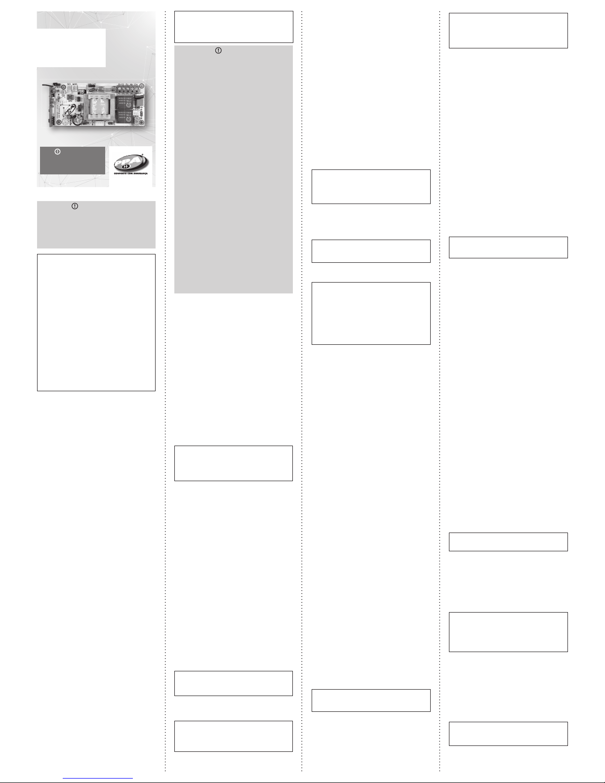
BOARD
FACILITY
CONNECT
TECHNICAL
MANUAL
WARNING
Do not opera te the equi pment
without f irst rea ding the
instructions manual.
P0464 0 - Rev. 0
of flash on the led. Each flash represents 10
seconds for the garage light.
5. Open jumper PROG.
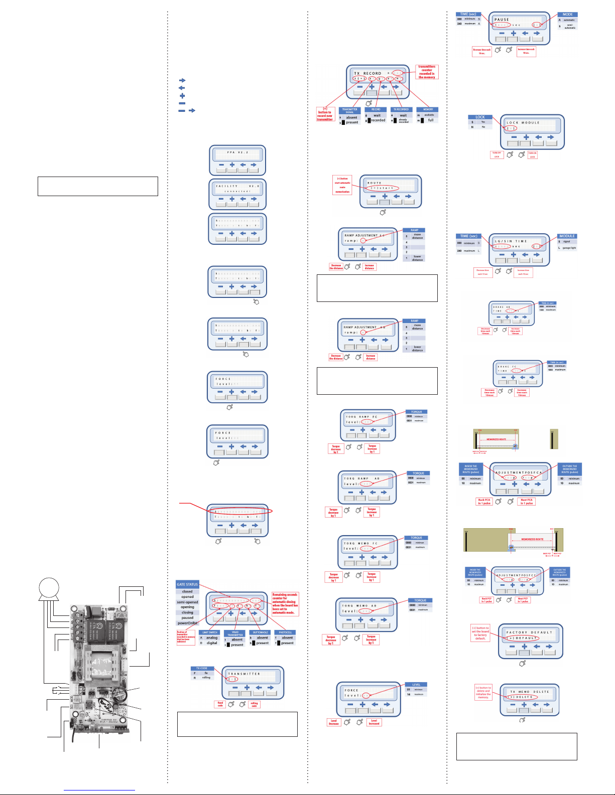
15. PROGRAMMER
It has the purpose of executing the programming of
internal functions independently and faster.
Button Function:
= Advance function;
= Back in function;
= Increase the value of the function.
= Decrementar o valor da função.
= Both buttons pressed simultaneously to
start motor.
Board to be connected, the programmer displays the
messages of Figures 1, 2 and 3 in sequence.
ADVANCE FUNCTION
BACK FUNCTION
INCREASE THE VALUE OF THE FUNCTION
DECREASE VALUE OF THE FUNCTION
COMMAND TO OPEN OR CLOSE THE GATE
Press and release both buttons simultaneously and
slowly to start the engine and observe the status of
the gate.
SCREEN INFORMATION
Displays the gate status information, sensors, and
transmitter position that released gate access.
TRANSMITTER
NOTE: : In attempt to program the type of transmitter
with the gate in moviment, the function will be
canceled and an audible alarm will be activated.
RECORD TRANSMITTER
1. It is not necessary to close the panel’s PROG
jumper.
2. Press and hold the transmitter button.
3. The indicator s on the screen will signal the
presence of the transmitter.
This type of adjustment is identical to “Independent
Piston Torque Adjustment for Opening and Closing”,
but it is valid only in the event of course.
For this setting, you must simultaneously press and
release the 2 buttons on the transmitter (recorded) 8
times.
12.TRIGGER TIME OF THE BRAKE
INDEPENDENT FOR OPENING AND CLOSING
This type of adjustment allows the electronic brake to
be turned off.
1. The gate must be stopped and not timed for
automatic closing.
2. Close the PROG jumper. The green SN led must
be dim.
3. Press and release simultaneously the 2 buttons on
the transmitter (recorded) 9 times. The SN led will
flash each time the buttons are released. Wait 5
seconds.
4. Then the SN led will turn off and wait for the limit
switch position to be programmed.
5. To select the brake adjustment at closing, press
and release the GRV button. The SN led will flash
once.
NOTE: In Case of the GRV button not pressed, the
adjustment of the brake will be open.
6. Adjusting the brake. The function has up to 11
adjustment levels.
Decrease the brake time (SN LED flashes
quickly) or off (SN LED flashes slow): Press
the left button of the transmitter until you find
the desired setting.
Increase the brake time (SN LED flashes
quickly): Press the right of the transmitter until
find the desired setting.
End of programmer: Open PROG jumper.
13. SELECT THE TYPE OF TRANSMITTER FIXE
CODE OR ROLING
1. The gate must be stopped and not timed por
automatic closing.
2. Close the PROG jumper. The green SN led must
be dim.
3. Simultaneously press and release the two buttons
on the transmitter (recorded) 10 times. The SN led
will flash each time the buttons are released. Wait
5 seconds.
4. Next, the led SN will be on waiting for the
configuration of the type of transmitter.
To transmitter fixed code: Press and release
the left button of the transmitter.
For rolling code transmitter: Press and release
the right button of the transmitter.
5. Open the PROG jumper.
End programming: Simultaneously press and release
the 2 transmitter buttons or open the PROG jumper.
After the transmitter type is selected, the memory will
be deleted.
14. SELECTING THE RELAY MODULE FUNCTION
1. The gate must be stopped and not timed for
automatic closing.Fechar o jumper PROG.
2. Close the PROG jumper. The green led SN should
be dim.
3. Simultaneously press and release the two buttons
on the transmitter (recorded) 11 times. The SN led
will flash each time the buttons are released. Wait
5 seconds.
4. Next, the SN LED will flash in the clock mode and
wait for the configuration of the relay module
function.
To lock: Press and release the right and left
buttons of the transmitter simultaneously.
For signalman: Press and release the left button
of the transmitter.
For garage light: Press and hold the right
button on the transmitter and count the number
4. Press and release the + button, and the g
indicator on the screen will indicate that you have
recorded.
5. The transmitter counter recorded n: on the screen
will be updated.
6. Remove transmitter button, and the s indicator on
the screen will be erased.
To record other buttons, repeat from item 2.
MEMORY COURSE
The board will enter the closing cycle until the limit
switch is found, and after 1 sec., Initializes the opening
cycle, storing the encoder time or pulses until the limit
switch is opened.
CLOSING RAMP
NOTE: : In attempt to program the closing ramp
with the gate in moviment, the function will be
canceled and an audible alarm will be activated.
OPENING RAMP
NOTE: In attempt to program the opening ramp
with the gate in moviment, the function will be
canceled and an audible alarm will be activated.
CLOSING RAMP TORQUE
OPENING RAMP TORQUE
CLOSING MEMORIZED TORQUE
OPENING MEMORIZED TORQUE
FORCE
Adjust the electronic clutch with the gate moving or
stopped, up to 14 levels.
PAUSE
Time adjustment for automatic closing when the gate
find the FCA opening limit switch.
LOCK
At the opening cycle command, if the lock is enabled
[S] and the module connected, it will be activated and
after 1 sec. The board will start the engine and after 2
sec. The lock will be turned off.
GARAGE LIGHT / TRAFFIC LIGHT
• For garage light, set time in xxx seconds, and when
the board finds the limit switch sensor FCF, it will
timer for shutdown.
• For traffic light, set the time to 000 seconds, and
when theboard finds the limit switch sensor FCF, it
will shut down.
• To activate the garage light or traffic light
functions, disable the lock module [N].
OPENING BRAKE TIME
CLOSING BRAKE TIME
OPENING ADJUST LIMIT SWITCH POSITION
CLOSING ADJUST LIMIT SWITCH POSITION
RESTORE FACTORY DEFAULT
DELETE TRANSMITTER
NOTE: In attempt to program the type of
transmitter with the gate in movimente, the function
will be canceled and an audible alarm will be
activated.
127 or 220V
(50 / 60 Hz)
FCA
FCF
Capacitor
starting motor
Separated
Receiver
Buttonhole
Optional
Module
Light, Signal,
Lock
Analog
Limit
Switch
Digital Limit Switch
RF Receiver 433,92 MHz
Button for TX
recording and
ajusting some
functions
Photocell
Limit switch
selection jumper
Programming
Jumper
Motor
Yellow
Red/Black
Black/Red
 Loading...