

F10R REFLECTIVE PHOTOCELL DETECTOR
INSTRUCTION MANUAL
P04985 - Rev. 2
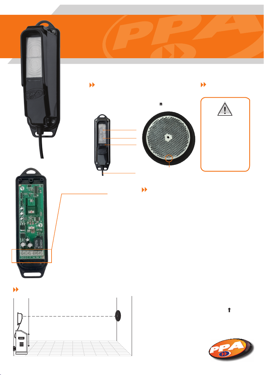
PHOTOCELL DETECTOR FEATURES:
F10R Reective
photocell detector
Transmitter
Receiver
LED Indicator
Wiring
Connection terminal
( + ) ( - ): The device must be powered
by a 12Vdc - 24Vdc auxiliary power
supply;
P: Pulsed output for PPA Control
boards;
NA, C and NF: Relay dry contact
outputs. Used for circuit keying
when the photocell is used in
normal mode, either open or closed.
PRECAUTIONS
Round Reector
- Make sure the
wiring is facing down;
- Install the photocell
away from obstacles
which could block the
beam.
Position indicator
(for installation)
SPECIFICATIONS
- Max range: 08 meters (~26.25 feet)
- Operating voltage: 12Vdc - 24Vdc;
- Current drain: 80mA;
- NO and NC outputs;
- Immediate triggering;
- Pulsed output for PPA Control boards.
INSTALLATION
X
Step 1: Attach the photocell detector the same side the control
board is installed, since it will both receive commands from it and
power it up. The receiver is attached the opposite side, with the
transmitter and receiver facing each other. When attaching the
round reector, mind the (Installation) Position Indicator, it must
face up. ( ). The photocell detector must be attached so
that the opening for the wiring faces down, in order to
avoid accidental water entering.
A installation diagram can be seen on the previous page.
COMFORT AND SECURITY
F10R REFLECTIVE PHOTOCELL DETECTOR
INSTRUCTION MANUAL
The height indicated by an “X” refers to the height of the
possible objects which will be detected by the device, such as
vehicles, people and pets. For example, for a 50cm (~1.65f) high
vehicle, the photocell detector must be installed over this
height, otherwise it will not detect the vehicle. One must
observe the minimum height (30 cm - ~0.99f), in order to both
ensure a proper operation and avoid false alarms.
Note: There is no maximum height for installing the photocell
detector.
Step 2: Set the operation mode according to the
following procedures
'Coded PPA' Mode:
'P' output of the photocell's connection terminal
connected to the 'FOT' output of the control board
'NA', 'C' and 'NF' outputs of the connection terminal
not connected.
:
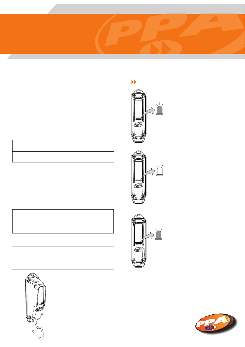
LED FUNCTIONS
LED indicator on: Misaligned
or blocked sensor.
ATIV/PASS Jumper: This jumper changes the relay operation
mode.
- Closed: Passive relay (Factory default setting).
- Open: Active relay (In this mode, the relay keeps activated
while the photocell detector is aligned, i.e., NO mode becomes
NC and vice versa).
NO (Normally Open) Mode:
'NA' output of the photocell's connection terminal
connected to the 'FOT' output of the control board
'C' output of the photocell's connection terminal
connected to the ( - ) output of the control board.
NC (Normally Closed) Mode:
'NF' output of the photocell's connection terminal
connected to the 'FOT output of the control board
'C' output of the photocell's connection terminal
connected to the ( - ) output of the control board.
STEP 3: Connect power to the
sensor by using an auxiliary power
supply, such as the control board.
Observe the polarity, the wires
must be connected to the auxiliary
power supply according to the
diagrams of the connection
terminal .
LED indicator off: optimal alignment.
LED indicator blinking: Function used for
installation; the blinking LED indicates
to the installer that the photocell detector
is sending the signal to the control board and
it is operating, but it is partially aligned, and
only needs a simple adjustment for optimal
alignment and proper operation.
NOTE: The slower the LED blinks, the closer to
the optimal alignment the photocell detector is;
if the LED starts blinking faster, it is less aligned.
COMFORT AND SECURITY
 Loading...