

PPA Eurus Custom Technician Manual
COMFORT whit SECURITY
COMFORT whit SECURITY
www.ppa.com.br
PPA - Portas e Portões Automáticos Ltda.
Av. Labieno da Costa Machado n-7 3526 - Distrito Industrial
CEP: 17.400-000 - Tel: (0**) 14 3407-1000
Garça/SP - Brasil
COMFORT whit SECURITY
COMFORT whit SECURITY
Technician’s Manual
Gate operator with micro-processed digital control for gates up to 300 Kg
Installation Manual
EURUS CUSTOM
Contents
* Installation Procedure .......................................................................... 2
* Tools .................................................................................................... 2
* Preparation of the gate before automation ........................................... 3
* Technical Characteristics .................................................................... 3
* Installing the rack ................................................................................ 4
* Releasing System ............................................................................... 6
* Main Characteristics............................................................................ 6
* Control unit Logical Function ............................................................... 7
* Access Buttons Memorization............................................................. 7
* Electronic Lock Transmitter Memorization .......................................... 8
* Turning on Electronic Lock .................................................................. 8
* Turning off Electronic Lock .................................................................. 9
* Turning off Buttons............................................................................... 9
* Blow out image .................................................................................... 10 e 11
* Parts List ............................................................................................ 12
* Memorizing Adjustments of Trimpots and Virtual Fuse ........................ 13
* Types of Virtual Fuse Protection .......................................................... 13
* Adjusting Trimpots ............................................................................... 14
* Configuring Jumpers ............................................................................ 15
* Auto light timer (LG) ............................................................................ 16
* Functions of Signaling Led .................................................................. 16
* Smoth Start ......................................................................................... 17
* Photocell ............................................................................................. 17
* Electrical Connections Scheme .......................................................... 18
*Warranty Terms .................................................................................... 19
CÓD. P14433 FORM. 150 REV.: 0
INSTALLATION PROCEDURE
Introduction: The perfect operation of this equipment and warranty depend
on the instructions included in this manual.
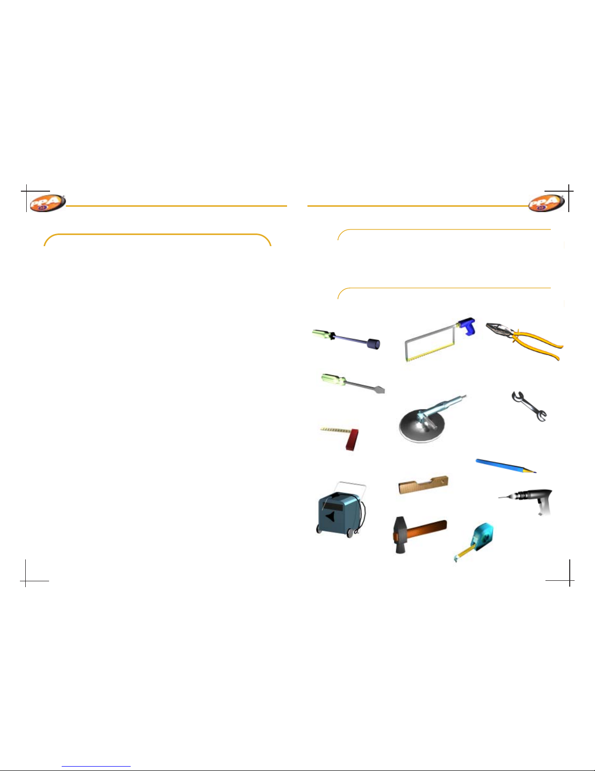
Here are some of the necessary tools for the assembly and installation of the
equipment:
TOOLS:
Cannon handle socket
wrench
Hack saw arc
Screwdriver
Setsquare
Sander
Pliers
Double open ended
spanners
Pencil
Welder
Drill
Level
Tape measure
Page 02
Drill
COMFORT whit SECURITY
COMFORT whit SECURITY
PREPARATION OF THE GATE BEFORE AUTOMATION
Before installation of the machine, check rolling, following the instructions
below:
1º Step: Move gate leaf manually and see the required
effort. Gate should move with ease.
2º Step: Move leaf back manually and check whether
the effort required was the same as the previous
operation.
Gate should have a strong structure and as
much as possible straight.
Pulleys should be of a diameter according to
gate dimensions. They also should be in rolling
perfect conditions and assembled in a way that the gate leaf has
stability during its trajectory. We recommend pulleys have at least
120mm of diameter.
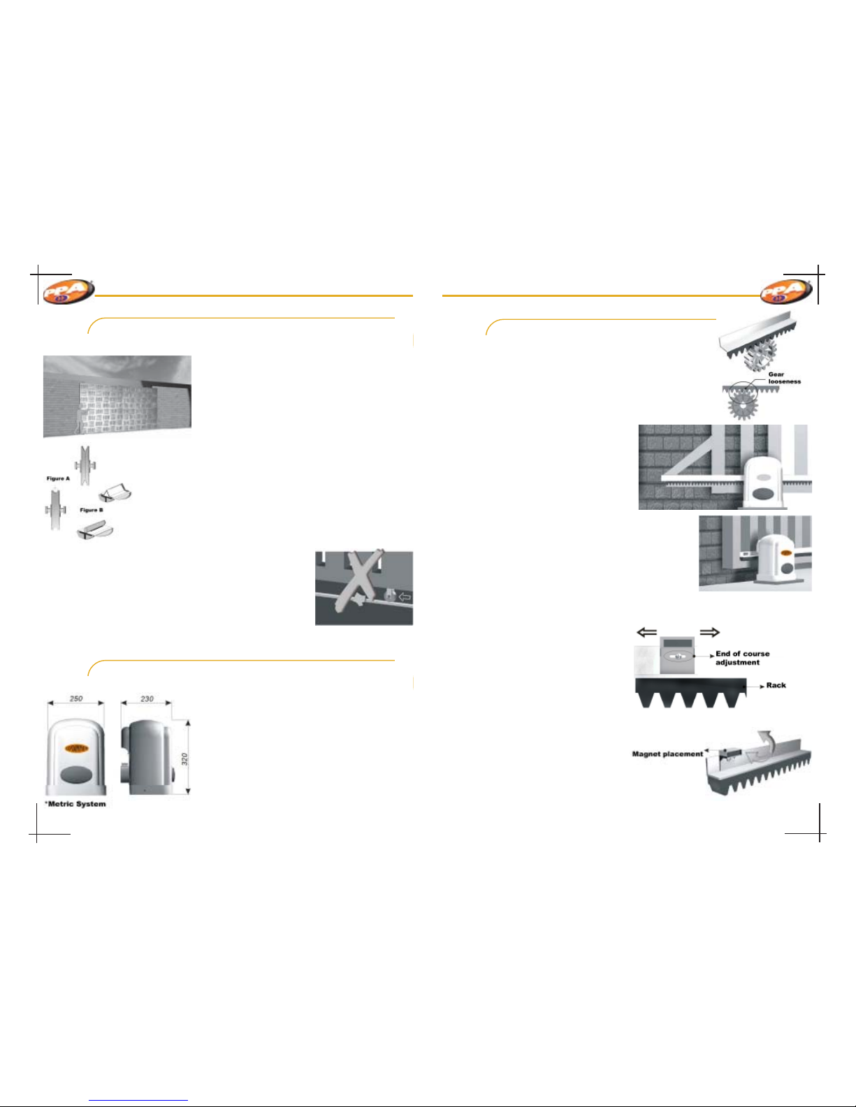
Figures beside represent two types of tracks and pulleys used.
The system that uses straight section (figure A – angle iron) shows
more resistance, therefore, more wear. On the other hand, the system
that uses round section (figure B) allows a better gate movement
and less resistance to the gate operator.
3º Step: Check if gate leaf does not stop during opening and closing
trajectory.
Gate rolling track should be perfectly straight and
occasionally cleaned from any element or dirt that
complicates pulleys sliding, as it is showed on picture
beside:
Observation: The information above is very important
because it can be prejudicial for gate operator
performance.
TECHNICAL CHARACTERISTICS
Equipment Dimensions
Source: ........................... 110/220V
Frequency: ..................... 50/60Hz
Rotation: ......................... 1450(50Hz)/ 1750(60Hz)
Reduction: ...................... 30:1
Protection: ...................... IP 44
Capacitor: ....................... 8uFx400V/ 20uF x 250V
Isolation: ......................... F
Packing dimensions: ...... 260 x 240 x 317 mm
Gate operator weight: ..... 9Kg
Max. gate weight : .......... 300Kg
INSTALLING THE RACK
1º Step: Set the machine on manual mode (see page 6),
open gate completely, and place rack on gear in a way
that it has 2mm between teeth. Make the fixation on leaf
every 30 or 40 cm using a welder or screw in the entire
extension of the gate leaf.
Observation:
In case the gate leaf is crooked,
provide shimes to assure rack
alignment. In certain cases, the rack will
exceed the leaf length. If that is the case,
provide an L-bracket so it does not jump
the track during the machine start.
2º Step: Feed control unit with 220v,
according to equipment voltage, to
record remote controls as it is
explained in this manual.
-With the gate on manual mode, place leaf in
the middle of course and switch equipment to
automatic mode.
-Turn power off temporarily and turn it on again;
activate remote control and check if gate opens
obeying the command. If gate opens, it will show that
rotation direction is correct. In case situation described
previously is not occurring, switch motor’s Red and
Black wire.
3º Step: Magnets Installation – with the
gate closed, place magnet support
facing the REED, open gate
completely and place the other
magnet facing the REED. Turn motor on and do the final test,
observing if REEDs are turning off
correctly. If it is necessary switch
plate connector.
After installing magnets
support, do fine adjustments and if
necessary use the opening situated
on magnet support to move the
magnet position, according to
illustration beside.
L-bracket detail
Page 03 Page 04
 Loading...