

PPA DZ IND. 1.0, DZ IND. 1.5, DZ 2.0 Technical Manual
www.ppa.com.br
+55 (14) 3407-1000
callcenter@ppa.com.br
DZ IND. 1.0 BRUSHLESS DC
DZ IND. 1.5 BRUSHLESS DC
DZ 2.0 ROBUST BRUSHLESS DC
Technical Manual
Av. Dr. Labieno da Costa Machado, 3526 - Distrito Industrial - CEP 17400-000 - Garça - SP - Brasil
MOTOPPAR INDÚSTRIA E COMÉRCIO DE AUTOMATIZADORES LTDA.
WARNING:
Do not use the product
without rst reading the
instruction manual.

EU DECLARATION OF INCORPORATION OF PARTLY COMPLETED MACHINERY
Identication Number: PPA CE 001 (Revision: 01)
Manufacturer:
Company Name: MOTOPPAR INDÚSTRIA E COMÉRCIO DE AUTOMATIZADORES LTDA.
Address: AV. DR LABIENO DA COSTA MACHADO, 3526
GARÇA, SÃO PAULO, 17400000 - BRASIL
Authorized Representative / Person authorized to compile the Technical File:
Company Name: PERES & SELLANI S.L.
Address: CARRER SALVADOR DALI, 3-1-1
SANT CUGAT DEL VALLÈS, 08173, BARCELONA - ESPAÑA
This declaration of conformity is issued under the sole responsibility of the manufacturer, which declares that:
The following partly completed machinery is the object of this declaration:
Product Type: AUTOMATIC GATE OPERATOR FOR SLIDING GATES
Models: DZ IND 2.0, DZ IND 1.5, DZ IND 1.0, DZ RIO 800, DZ RIO 500
The object of the declaration described above is in conformity with the following essential requirements of Directive
2006/42/EC on machinery:
1.1.1, 1.1.2, 1.1.3, 1.1.5, 1.2.1, 1.2.3, 1.2.4.1, 1.2.4.2, 1.2.4.3, 1.2.6, 1.5.1, 1.5.14, 1.5.5, 1.5.6, 1.6.1, 1.6.3, 1.7
The object of the declaration described above is in conformity with the relevant Community harmonization legislation:
DIRECTIVE 2014/30/EU OF THE EUROPEAN PARLIAMENT AND OF THE COUNCIL of 26 February 2014 on the
harmonisation of the laws of the Member States relating to electromagnetic compatibility
DIRECTIVE 2011/65/EU OF THE EUROPEAN PARLIAMENT AND OF THE COUNCIL of 8 June 2011 on the
restriction of the use of certain hazardous substances in electrical and electronic equipment
The relevant harmonised standards considered for compliance are:
Machinery Directive (2006/42/EC):
IEC 60335-1:2010+AMD1:2013 CSV/COR1:2014, IEC 60335-2-103:2015, ISO 12100:2010
EMC Directive (2014/30/EU):
IEC 61000-4-2, IEC 61000-4-3, IEC 61000-4-4, IEC 61000-4-5, IEC 61000-4-6, IEC 61000-4-11, IEC 610004-13
RoHS Directive (2011/65/EU):
EN 50581:2012
The relevant technical documentation is compiled in accordance with Annex VII, part B of Directive 2006/42/EC;
In response to a reasoned request by the national authorities, the relevant information will be transmitted;
The partly completed machinery must not be put into service until the nal machinery into which it is to be incorporated has
been declared in conformity with the provisions of the Machinery Directive (2006/42/EC)
GARÇA, 01/02/2019
INdEX
IMPORTANT SAFETY INSTRUCTIONS ........................................................................................ 4
TECHNICAL CHARACTERISTICS .................................................................................................. 5
TOOLS REQUIRED FOR INSTALLATION ..................................................................................... 6
TYPICAL INSTALLATION OVERVIEW .......................................................................................... 6
ELECTRICAL INSTALLATION ......................................................................................................... 7
CARE WITH ELECTRICAL INSTALLATION .................................................................................. 7
CARE WITH THE GATE BEFORE THE AUTOMATION ..............................................................8
INSTALLATION OF THE OPERATOR ............................................................................................ 9
INSTALLATION ANALOG LIMIT SWITCHES ............................................................................14
TRIFLEX CONNECT BRUSHLESS BOARD.................................................................................17
LOGICAL FUNCTION OF THE SYSTEM FOR GATES ......................................................22
PARAMETERS PROGRAMMING .......................................................................................... 22
ERASE THE RECOGNIZED GATE TRAVEL .........................................................................28
APPLY FACTORY DEFAULTS .................................................................................................28
RECORD A RADIO FREQUENCY TRANSMITTER (RF) ...................................................29
SELECTION OF RF RECEPTION PROTOCOL (CF / CR) ..................................................29
DELETE ALL RF TRANSMITTERS RECORDED .................................................................29
ANTI-CRUSHING SYSTEM ....................................................................................................29
ENCODER OPERATION TEST ...............................................................................................30
EVENTS AND FAILURES INDICATIONS .............................................................................30
MAINTENANCE AND TROUBLESHOOTING ...........................................................................31
EXPLODED VIEW DZ IND 1.0 BRUSHLESS DC. ......................................................................34
EXPLODED VIEW DZ IND 1.5 BRUSHLESS DC. ......................................................................36
EXPLODED VIEW DZ 2.0 ROBUST BRUSHLESS DC .............................................................. 38
Samuel Peres
MOTOPPAR INDÚSTRIA E COMÉRCIO DE AUTOMATIZADORES LTDA.
CEO
3
IMPORTANT SAFETY INSTRUCTIONS
THE FULL AUTOMATION MUST COMPLY WITH THE CURRENT EUROPEAN MACHINERY
DIRECTIVE, IN PARTICULAR WITH THE STANDARDS: EN 13241-1, EN 12635, EN 602041, EN 12445, EN 12453, EN 12978
• Installation shall be carried out by qualifed personnel only, who can issue the
Certifcate of Compliance concerning the whole installation (Machine Directive
2006/42/CE).
• Before installing the equipment, it is important that the specialist installer follow
all instructions given in this technical manual and in the user manual.
• Never let children operate or play with door controls. Keep the remote control
away from children. With the help of the user manual, the installer must present
all information, uses and safety items of the equipment to the end user.
• Before installing the operator, make sure that the local power supply is compatible
with that required on the equipment identifcation label;
• The electrical installation must be provided with a device (eg. circuit breaker) to
ensure the complete disconnect of the equipment from the power supply, as well
a proper cabling, grounding and residual current devices for users protection.
• The product must be installed in an environment that suits the IP rating (IPX4) of
the product.
• Ensure that entrapment between the gate and the surrounding xed parts due to
the movement of the gate is avoided, according to harmonized standars (i.e. DIN
EN 349, ISO EN 14120)
• The opening and closing forces should be measured and tested in accordance
with BS EN 12445 (Test method) using an appropriate tool.
• Protective devices installed must comply with EN 12978 (Safety devices).
• Check the automation periodically, with special attention to cables, springs and
mechanic parts for wear and tear, damages and unbalancing. Do not use the
opener when service or adjustment work is required. Have a qualifed service
person to make repairs to gate hardware.
• Only carry out electrical connections once the electricity supply to the system has
been switched o. Disconnect any buer batteries or Nobreaks present.
• Use the manual release only when the gate is not moving.
• Save these instructions for later reference. The original instructions are in
Portuguese.
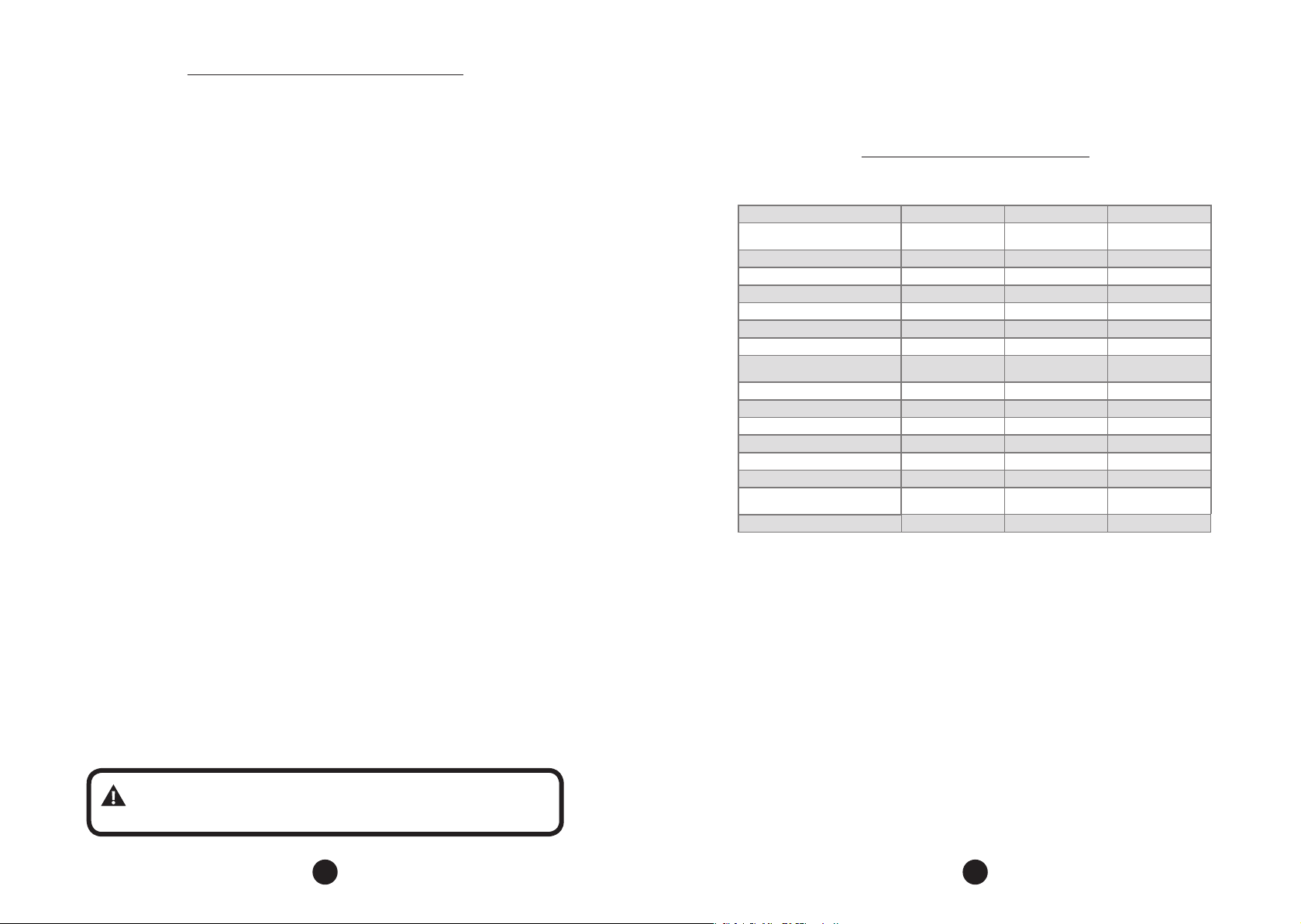
TECHNICAL CHARACTERISTICS
OPERATOR TYPE Slider Slider Slider
MODEL
RATED VOLTAGE 230 V 230 V 230 V
NOMINAL FREQUENCY 50 Hz 50 Hz 50 Hz
RATED POWER 350 W 400 W 450 W
MOTOR ROTATION 4500 rpm 4500 rpm 4500 rpm
MOTOR CURRENT 3A 3A 3,2 A
MOTOR REDUCTION 1:40 1:40 1:40
LINEAR SPEED
PERFORMANCE 60 cycles/h 60 cycles/h 60 cycles/h
PROTECTION DEGREE IPX4 IPX4 IPX4
TEMPERATURE RANGE -20 ºC / +50°C -20 ºC / +50°C -20 ºC / +50°C
ISOLATION TYPE Class B, 130°C Class B, 130°C Class B, 130°C
LIMIT SWITCH Hybrid Hybrid Hybrid
MAXIMUM GATE LEAF WEIGHT 1000 Kg 1500 Kg 2000 Kg
MAXIMUM GATE DIMENSIONS
NOMINAL LOAD 450 N 580 N 850 N
DZ IND. 1.0
BRUSHLESS DC
Z12 = 0,42 m/s
Z17 = 0,60 m/s
Height: 2,5m
Length: 10m
DZ IND. 1.5
BRUSHLESS DC
Z12 = 0,42 m/s
Z17 = 0,60 m/s
Height: 2,5m
Length: 10m
DZ 2.0 ROBUST
BRUSHLESS DC
Z12 = 0,42 m/s
Z17 = 0,60 m/s
Height: 2,5m
Length: 10m
WARNING: Important safety instructions. Follow all instructions
in this manual. Incorrect installation can lead to serious injury.
4 5
TOOLS REQUIREd FOR INSTALLATION
ELECTRICAL INSTALLATION
Here are some tools required to install the operator:
PLIERS SAWING BOW SOCKET WRENCH SCREWDRIVER NUT WRENCH
LADDER
WELDING MACHINE HAMMER LEVEL TAPE MEASURE
FRAME DRILL PENCIL SANDER
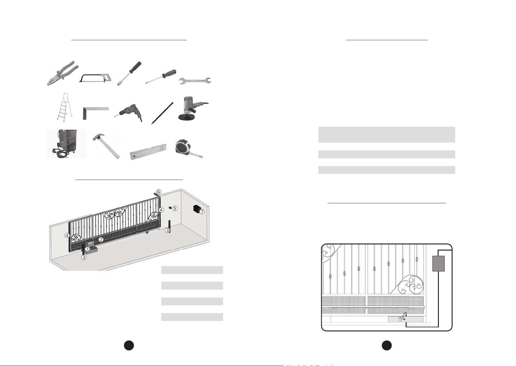
TYPICAL INSTALLATION OVERVIEW
For electrical installation, the network shall contain the following characteristics:
- 230V-50Hz power supply;
The passage of the wiring must be made through conduits between:
- the electrical distribution box and the total disconnect device
- the total disconnect device and the operator supply terminals;
- the control board and the (optional) external pushbutton;
- the control board and the photocells;
The wires used must comply with the local standards. The recommended cable
sizes are listed below:
DZ IND 1.0 BRUSHLESS DC
DZ IND 1.5 BRUSHLESS DC
DZ 2.0 ROBUST BRUSHLESS DC
Power supply 230V 3 x 1,5 mm² 50 m
Photocells 2 x 0,5 mm² 10 m
Safety Edges 2 x 0,5 mm² 10 m
Pushbutton 2 x 0,5 mm² 5 m*
Flashing light 2 x 1 mm² 20 m
*For further distances, please contact technical support.
Cable Section Maximum Lenght
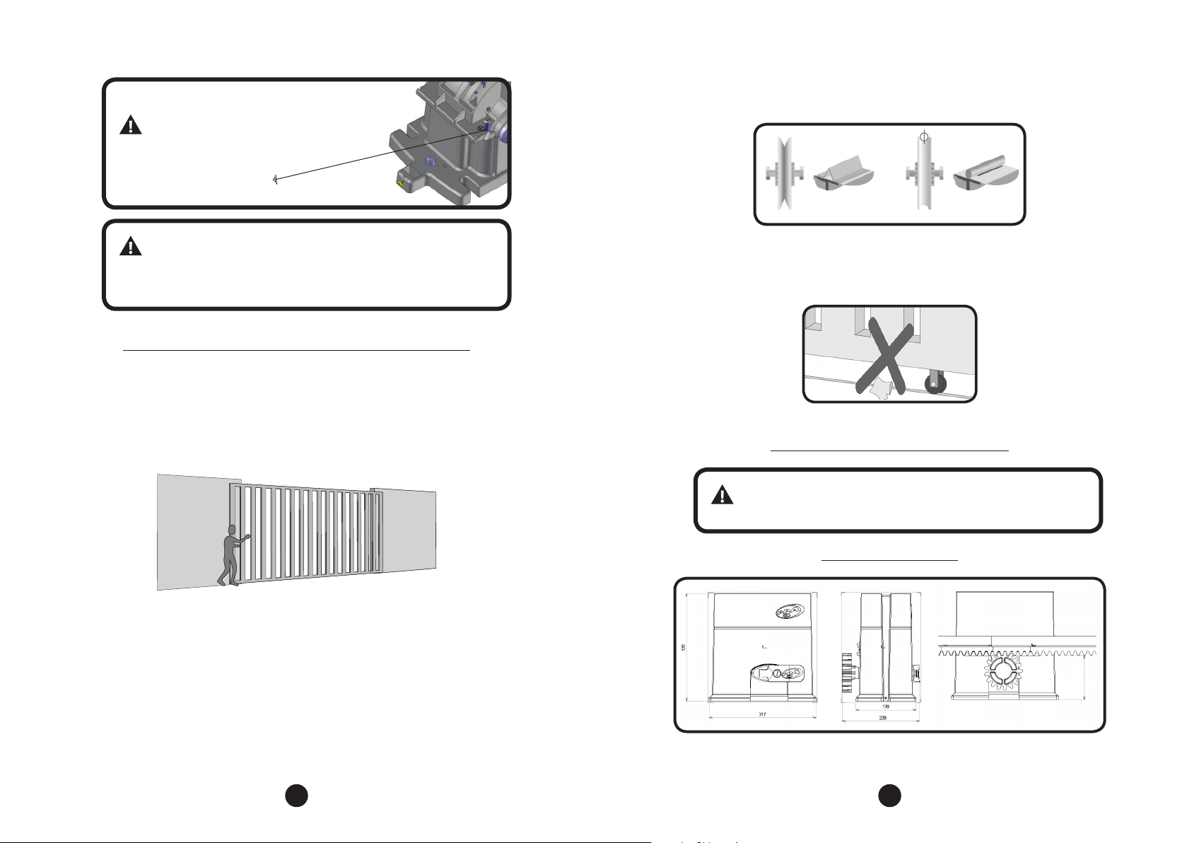
CARE WITH ELECTRICAL INSTALLATION
To avoid damage to the wiring, it is important that all conductors are properly
attached to the operator. Wiring must be done through conduits, passing internally
through the base of the oor, ensuring that none of the wiring conductors are
trapped and damaged.
ITEM DESCRIPTION
1 Gate Operator
2 Rack
3 Photocells
4 Safety Edges
5 Pushbutton
6 Flashing light
7 Power supply 230V
6 7
It is mandatory that the
Z12 = 117
Z17 = 132
Z12 = 117
Z17 = 132
ground terminal is connected
to the grounding cable
network.
and consequently greater wear. The circular section (Figure B) allows a better
displacement of the gate and less friction for the operator.
FIGURE A FIGURE B
IMPORTANT
The electrical installation must have a residual current (RCD)
device with a rated residual current of 30 mA.
CARE WITH THE GATE bEFORE THE AUTOMATION
Before adapting the machine to the gate, check the gate movement by following
the instructions below:
Step 1: Before installing the operator, check if the gate is in good mechanical
condition, ie opening and closing properly. Open the gate manually and observe
the required e ort. This e ort should be minimal for the entire length of the rail.
Step 2: Close the gate manually and check whether the e ort was the same as the
previous operation.
The gate shall have a sturdy and, as far as possible, non-deformable structure. The
pulleys shall have a diameter suitable to the dimensions of the gate, shall be in
perfect running condition and shall be mounted in such a way that the gate leaf
has stability along all its displacement. We recommend pulleys with a diameter of
at least 120 mm.
The gures below represent the two types of rails and pulleys used. The system
that uses straight section (Figure A - angle bracket) exhibits greater friction
Step 3: Check wether the gate leaf does not jam in the opening and closing
movement. The slide rail of the gate must be perfectly rectilinear, undercut, and clear
of any element or dirt that makes it di cult to slide the pulleys in their entire length.
INSTALLATION OF THE OPERATOR
Before installing the operator, remove all unnecessary cables and
disable any equipment or system connected to the mains.
EQUIPMENT DIMENSIONS
Z12 = 117
Z17 = 132
NOTE: All measurements are in milimeters.
8 9
The correct operation of this equipment depends on the instructions in this
manual. To secure the equipment, proceed as follows:
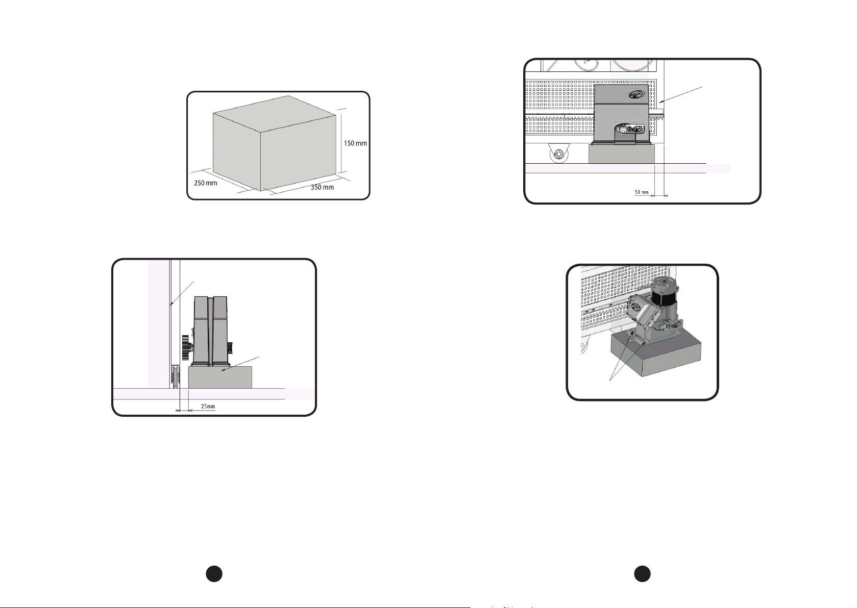
Step 1: Make sure the oor
is rm enough so that the
equipment can be screwed on
a level. If it does not comply
with the requirement, provide
a concrete base, following the
guidelines in the right image:
GATE LEAF
Step 2: The dimensions of the base should be appropriate for the dimensions of
the operator. The concrete base should be at a distance of approximately 25 mm
from the face of the gate leaf.
GATE LEAF
SIDE VIEW
CONCRETE BASE
Step 3: When the conditions are fullled, open the gate and position the operator
near the face of the gate leaf, obeying the 50 mm measurement between the leaf
end and the operator.
Step 4: Pre-align the operator with the gate, positioning the rack over the gear
and pushing the assembly to the gate. Then mark the xing holes in the oor or
concrete base.
MARK THE FIXING HOLES
ON THE FLOOR
Step 5: Drill the holes for fastening. Place the operator aligned to the gate and
insert the 3/8” x 3.3/4” bolts without tightening them. Move the gate, making sure
that it does not lean against the operation during the during its travel. If this occurs,
pull back the operator.
10 11
 Loading...