

Page 1

MOTOPPAR INDÚSTRIA E COMÉRCIO DE AUTOMATIZADORES LTDA.
A
v. Dr. Labieno da Costa Machado, 3526 - Distrito Industrial
CEP 17400-000 - Garça - SP - Brasil
Fone / Fax: (14) 3407-1100
www.ppa.com.br
Page 2
TECHNICAL MANUAL
DZ HOME
Warning:
Do not use the
product without
first reading the
instruction
Page 3

INDEX
Important safety instructions ............................................................................. 3
Technical characteristics ................................................................................... 4
Tools required for installation .............................................................................5
Electrical installation .......................................................................................... 5
Care with the electrical installation .................................................................... 6
Care with the gate before operator ...................................................................7
Installing and fixing the operator ....................................................................... 8
Equipment dimensions ...................................................................................... 8
Analog limit switch installation ...........................................................................13
Maintenance ...................................................................................................... 16
2
Page 4
IMPORTANT SAFETY INSTRUCTION
Recommendation:
For the installation of the equipment, it is important that the specialized
installer follow all the instructions quoted in this TECHNICAL MANUAL
and in the USER MANUAL.
With the USER MANUAL, the installer must present all information,
uses and safety items of the equipment to the user.
Before using the DZ NEW HOME ANALOG OPERATOR, read and
strictly follow all the instructions contained in this manual.
- Before installing the operator system, make sure that the local
electrical network is compatible with the one required on the
equipment identification label;
- Do not connect the mains until installation / maintenance is complete.
Always make electrical connections to the board with the mains
switched off;
- After installation, make sure that the parts of the gate do not extend
through the roads and public promenade;
- It is mandatory to use full shutdown devices in the operator system.
3
Page 5
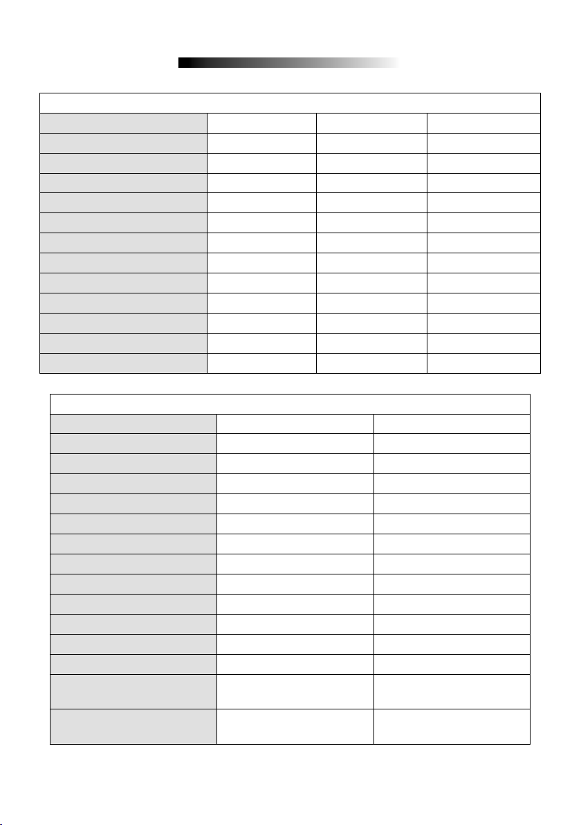
TECHNICAL CHARACTERISTICS
DZ HOME
OPERATOR TYPE SLIDING SLIDING SLIDING
RATED VOLTAGE 220 V 220 V 127 V
NOMINAL FREQUENCY 60 Hz 50 Hz 60 Hz
RATED POWER 460 W 470 W 335 W
MOTOR ROTATION 1740 rpm 1455 rpm 1740 rpm
NOMINAL CHAIN 2,15 A 2,37 A 2,86 A
REDUCTION 1:24 1:24 1:24
LINEAR SPEED 16,4 m/min 13,7 m/min 16,4 m/min
PERFORMANCE 30 cycles/h 30 cycles/h 30 cycles/h
DEGREE PROTECTION IPX 4 IPX 4 IPX 4
TEMPERATURE RANGE -5° C / +50° C -5° C / +50° C -5° C / +50° C
ISOLATION TYPE Class B, 130 ° C Class B, 130 ° C Class B, 130 ° C
LIMIT SWITCH ANALOG ANALOG ANALOG
DZ HOME JET FLEX / DZ HOME BLDC
OPERATOR TYPE BLDC SLIDING JET FLEX SLIDING
RATED VOLTAGE 220 V / 127 V 220 V / 127 V
NOMINAL FREQUENCY 60 Hz 60 Hz
RATED POWER 100W / 130W 100W / 130W
MOTOR ROTATION 4500 rpm 4365 RPM
NOMINAL CHAIN 0,7A / 1,4A 2,75 A / 3,6 A
REDUCTION 1:22 1:22
LINEAR SPEED 36 m/min 41 m/min
PERFORMANCE 100 cycles/h 40 cycles/h
DEGREE PROTECTION IPX 4 IPX 4
TEMPERATURE RANGE -5° C / +50° C -5° C / +50° C
ISOLATION TYPE Class B, 130 ° C Class B, 130 ° C
LIMIT SWITCH Hybrid Hybrid
MAX. MASS FROM THE
GATE LEAF
MAXIMUM DIMENSION;
GATE
HEIGHT = 2,5 m LENGTH
400kg 400kg
HEIGHT = 2,5 m LENGTH
= 3,0 m
= 3,0 m
4
Page 6
TOOLS REQUIRED FOR INSTALLATION
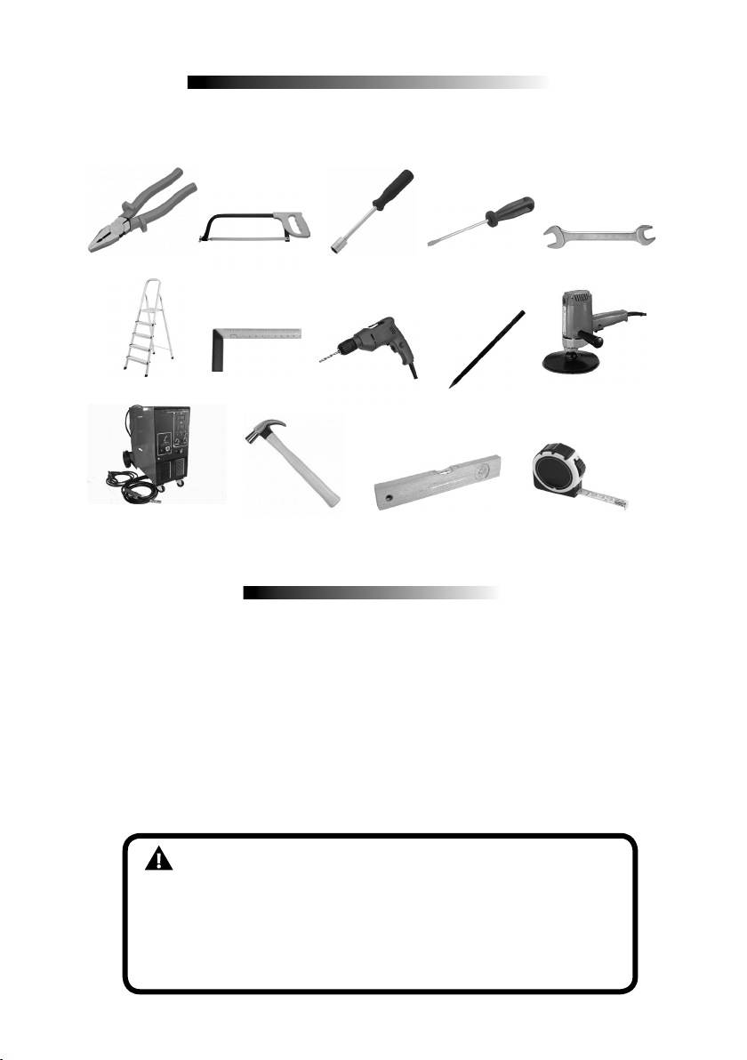
Here are some tools required to install the operator:
PLIERS
LADDER
WELDING MACHINE HAMMER LEVEL TAPE MEASURE
SAWING BOW SOCKET WRENCH SCREWDRIVER NUT WRENCH
FRAME DRILL PENCIL SANDER
ELECTRICAL INSTALLATION
For electrical installation, the network shall contain the following characteristics:
- Electric network 127V or 220V;
- Have 5A circuit breakers in the electrical distribution box;
- 3/4 "diameter conduit between the electrical distribution box and the total
disconnect device;
- 3/4 "diameter conduit between the total shut-off device and the operator
connection point;
- 1/2 "diameter conduits for buttonhole, external and optional;
- 1/2 "diameter for safety photocells (optional).
- The cable for the fixed wiring must comply with NBR NM 247-3;
-The power conductor of a product for internal use must be a
flexible cable 3 x 0.75 mm²; 500 V, according to the norm NBR
NM 247-5;
-The power conductor of a product for external use must be a
3 x 0.75 mm² flexible cable; 500 V, according to IEC 60245-57.
5
Page 7
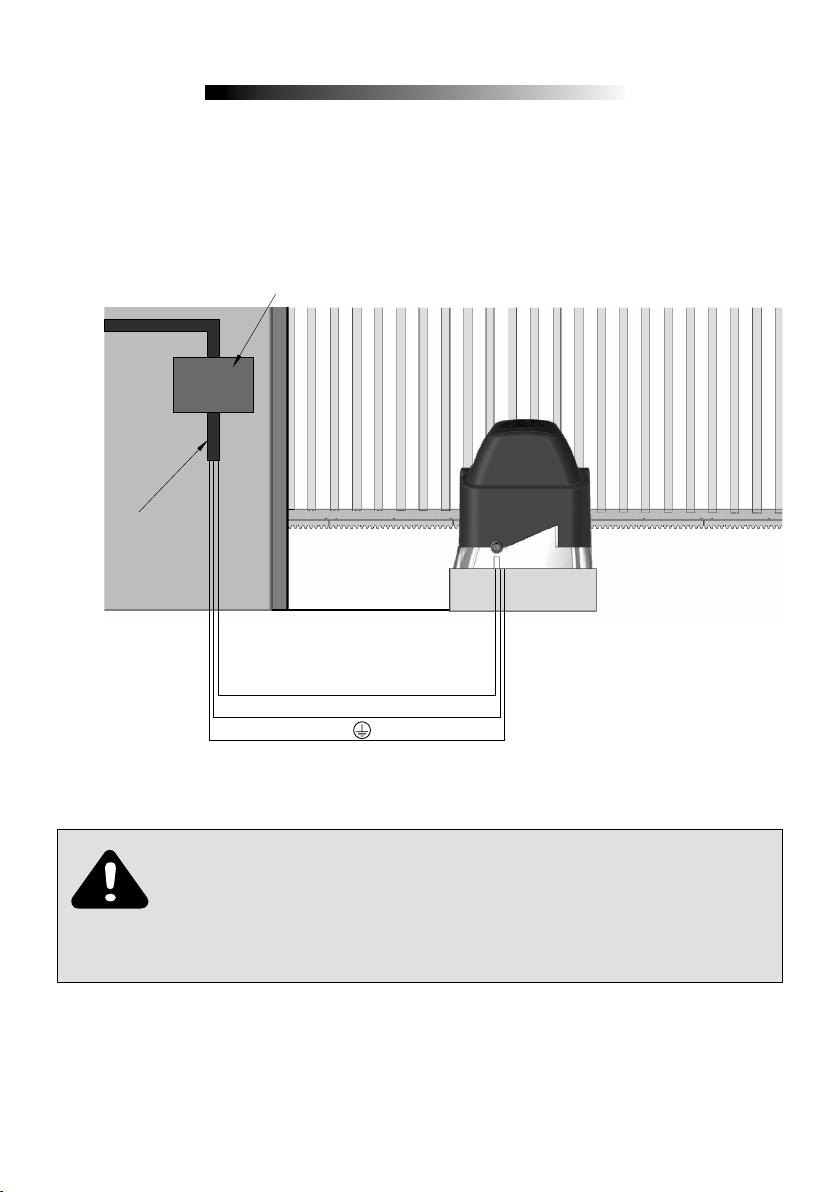
CARE WITH ELECTRICAL INSTALLATION
CONDUIT
SLIDING WAY
To avoid damage to the wiring, it is important that all conductors be properly
attached to the operator. Wiring must be done through conduits, passing internally
through the base of the floor, ensuring that none of the wiring conductors are
trapped and damaged.
6
L1
L2
IMPORTANT
The device must be powered by a residual current (DR) device with
a rated residual current of more than 30 mA.
Page 8
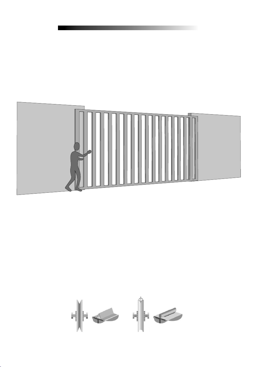
CARE WITH THE GATE BEFORE OPERATOR
Before adapting the machine to the gate, check the slide by following the
instructions below:
1º Step: Before Installing the operator, check that the gate is in good mechanical
condition, ie opening and closing properly. Open the gate manually and observe
the effort required. This effort should be minimal over the entire length of the course.
2º Step: Close the gate manually and check whether the exertion exerted was the
same as the previous operation.
The gate shall have a sturdy and, as far as possible, non-deformable structure.
The pulleys shall be of diameter conforming to the dimensions of the gate, are in
perfect running condition and are mounted in such a way that the gate leaf has
stability throughout its displacement. We recommend sheaves with a diameter of
at least 120 mm.
The figures below represent the two types of rails and pulleys used. The system
that uses straight section (Figure A - angle bracket) presents greater friction
and consequently greater wear. The circular section (Figure B) allows a better
displacement of the gate and less friction for the operator.
FIGURE A
FIGURE B
7
Page 9
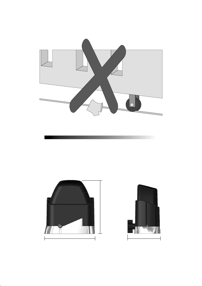
3º Step. Make sure that the gate leaf does not jam in the opening and closing
movement. The slide rail of the gate must be perfectly rectilinear, level, unobstructed
periodically from any element or dirt that makes it difficult to slide the pulleys all the
way, as shown in the figure below.
INSTALLATION AND FIXING THE OPERATOR
Before installing the operator, remove all unnecessary cables and disable any
equipment or system connected to the mains.
EQUIPMENT DIMENSIONS
240 mm
226 mm
8
160 mm
Page 10
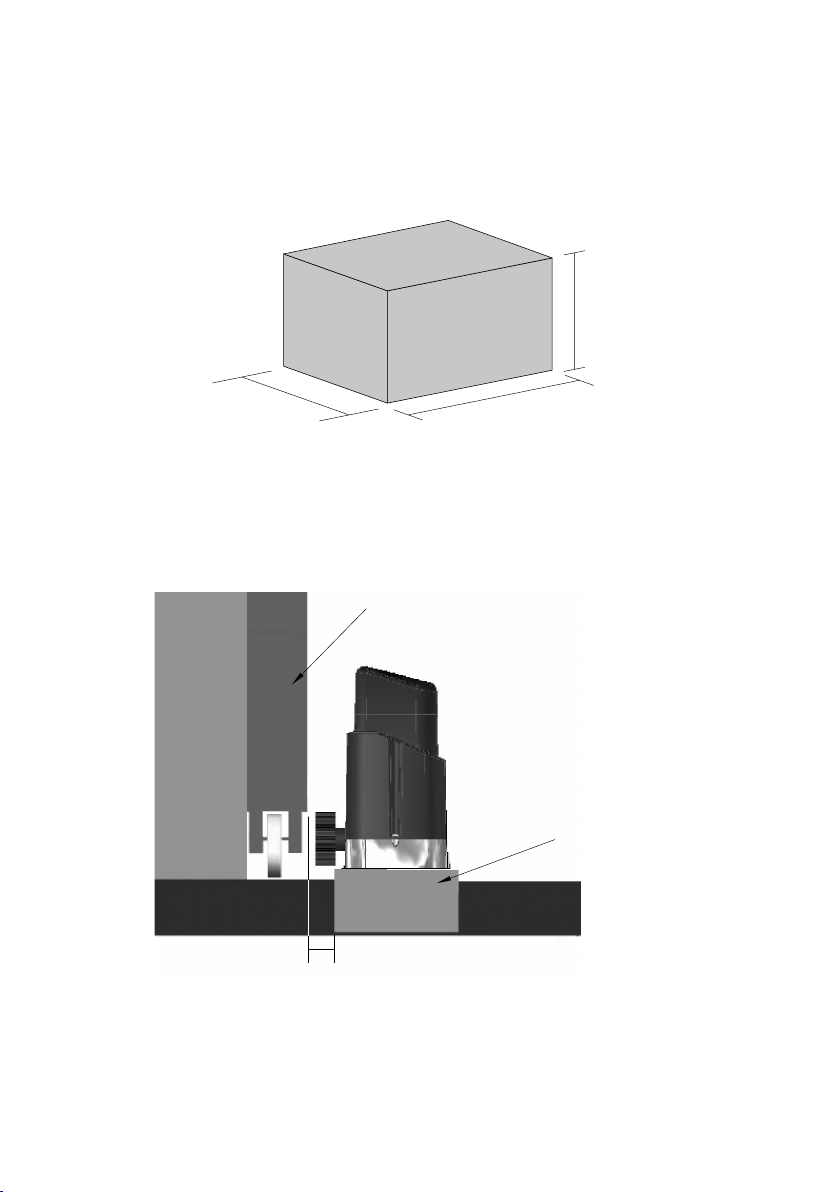
The correct operation of this equipment depends on the instructions in this manual.
GATE LEAF
mm
To secure the equipment, proceed as follows:
1º Step: Make sure that the floor is firm enough so that the equipment can be
screwed so that it is level. If it does not comply with the requirement, provide a
concrete base, following the guidelines below:
150
250 mm
300 mm
2º Step: Base dimensions should be appropriate for the dimensions of the
operator. The concrete base should be at a distance of approximately 20 mm
from the face of the gate leaf.
SIDE VIEW
CONCRETE BASE
9
Page 11
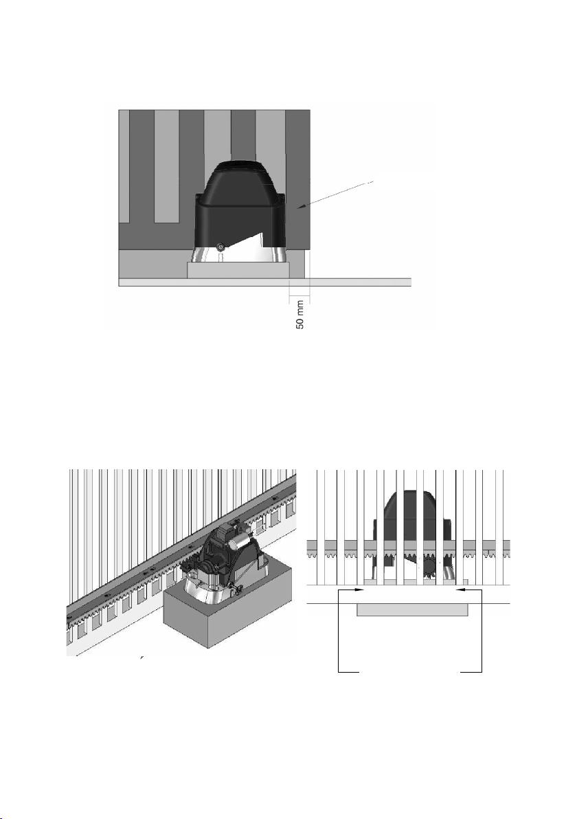
3º Step: Once the conditions have been fulfilled, open the gate completely and
FIXING THE FLOOR
OF FIXING THE FLOOR
position the operator system near the face of the gate leaf, obeying the 50 mm
measurement between the leaf end and the operator.
GATE LEAF
4º Step: Pre-align the operator to the gate, positioning the rack over the gear and
pushing the assembly against the gate. Then mark the fixing holes in the floor or
concrete base.
10
MARK THE HOLES OF
MARK THE HOLES
Page 12
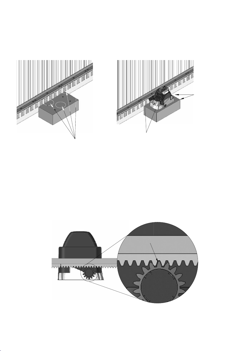
5º Step: Make the hole for the fixing, positioning the operator aligned to the
gate. Before tightening the S ¼ "x 2 ½" bolts, move the gate, making sure that
it does not lean against the operator in the course of its course. If this occurs,
back off the operator.
PLACE 2 SCREWS
S ¼ "X 2 ½"
WITH S10
BUSHING
PLACE 2 SCREWS S ¼ "X 2 ½"
HOLES OF FIXING
THE OPERATOR
WITH S10 BUSHING
6º Step: With the operator unlocked, position the rack bar on the gear and aligned
with the gate.
It is necessary to leave a gap of approximately 2 mm between the tooth top of the
gear and rack tooth bottom.
2 mm GAP
11
Page 13
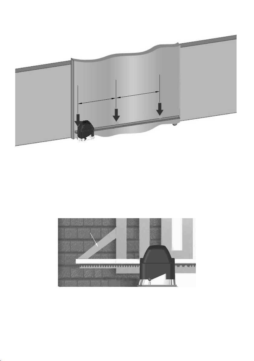
7º Step: Fix the rack to the entire length of the gate leaf with solder or screw every
300 or 400 mm.
300 or
300 or
400 mm
400 mm
8º Step: If the door leaf is warped, provide shims to ensure the alignment of
the rack. There are cases where the rack should pass the length of the leaf. In
this case, provide a french hand so you do not jump the teeth when starting
the machine.
12
FRENCH HAND
Page 14
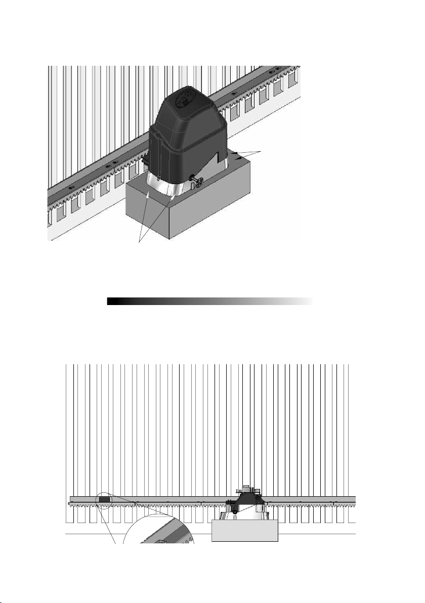
9º Step: After fixing the rack, definitely fix the operator on the floor or concrete
base, definitely tightening the screws.
TIGHTEN THE 2 SCREWS S ¼
"X 2 ½"
FOR FIXATION
TIGHTEN THE 2 SCREWS S ¼ "X 2 ½"
FOR FIXATION
ANALOG LIMIT SWITCH INSTALLATION
1º Step: With the gate closed, place the magnet holder in the rack, positioned in
front with the REED of the operator. This magnet will act as a closing limit switch.
13
Page 15
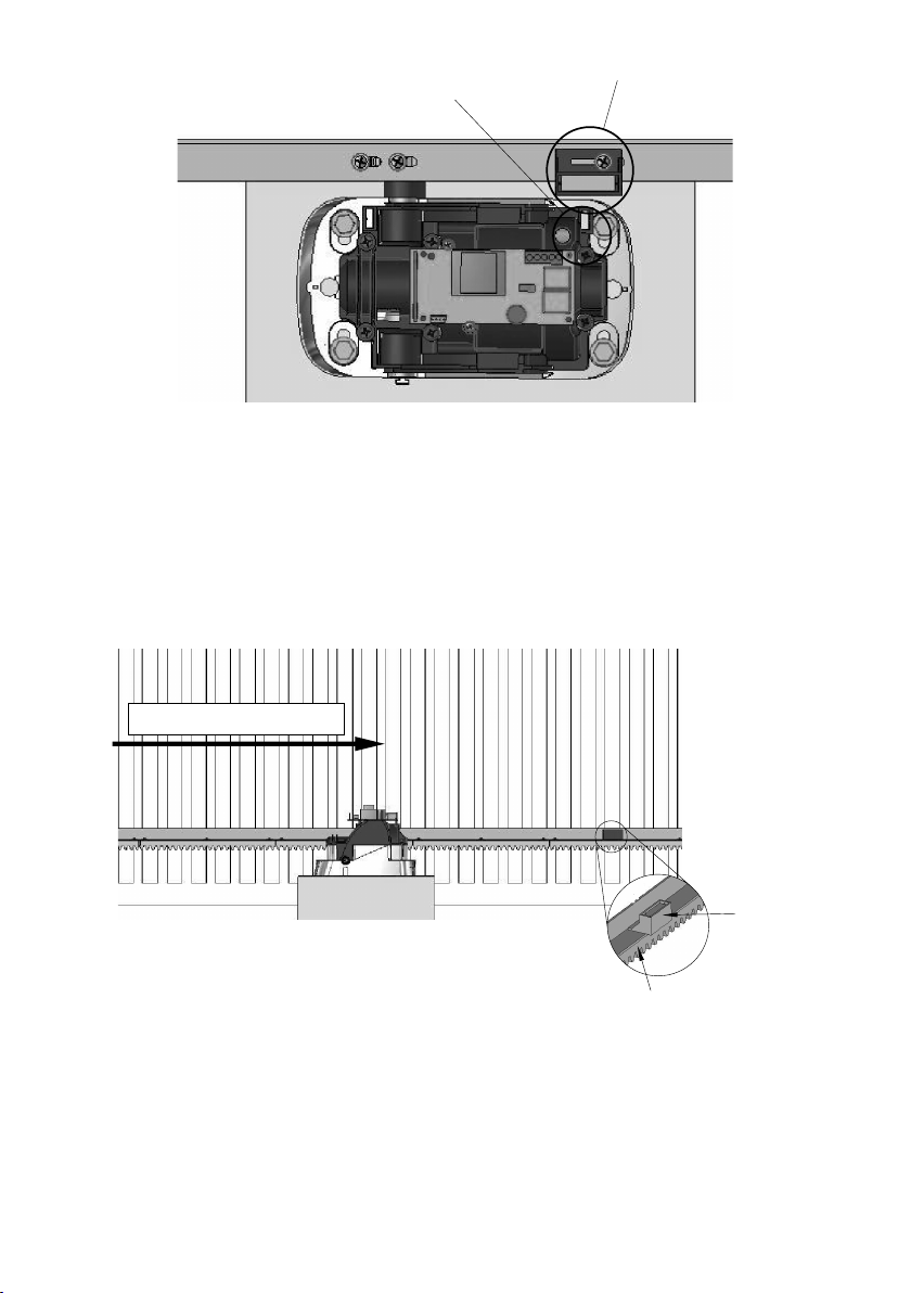
MAGNET SUPORT
REED SUPORT
UPPER VIEW
RACK
2º Step: Fully open the gate and place the other magnet holder on the rack, facing the
REED operator. This will act as a magnet to opening limit switch.
14
OPENING GATE
MAGNET
SUPORT
Page 16
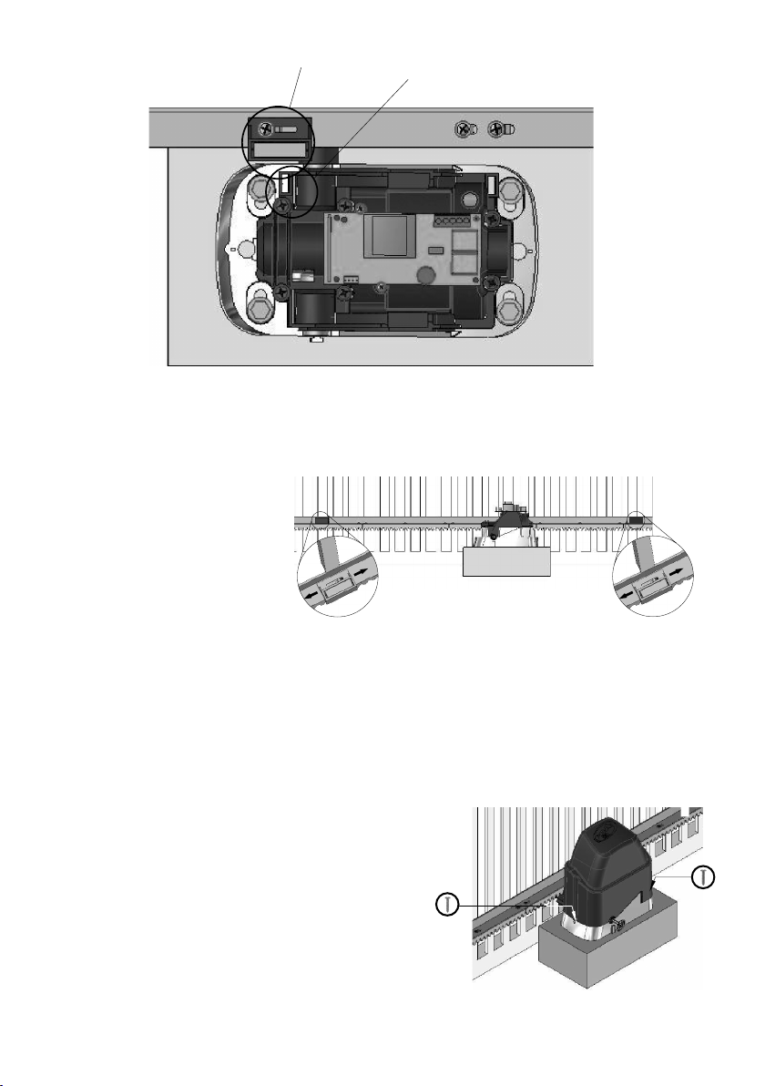
MAGNET SUPORT
UPPER VIEW
ADJUSTMENT
ADJUSTMENT
3º Step: Start the engine and
see if the REED's are shutting
off properly. If necessary,
invert the connector on the
board.
After attaching the magnet
holders, make final
adjustments by moving to
BRACKET
the right or left, depending
on the desired setting.
REED SUPORT
BRACKET
4º Step: To finalize the installation of the
operator, it is mandatory before screwing the
fairing with 2 x 3.5 x 16 mm screws (available
in the kit).
15
Page 17
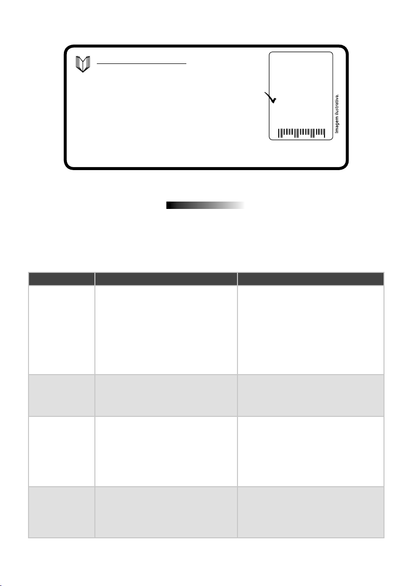
BOARD COMMAND
Check the label attached to the
product (according to the model on
the side) which is the board part of
the operator. After doing this, refer
to the board manual that is available
Lote:
Code:
Model:
Reduction:
Technology:
Voltage:
Board:
Size:
Assembly:
Fairing:
Gear:
for download at www.ppa.com and
make all connections and settings.
MAINTENANCE
In the table below, we will mention some PROBLEMS - DEFECTS, PROBABLE
CAUSES AND CORRECTIONS - which may occur in the operator. Before any
maintenance, it is necessary to completely disconnect the mains.
DEFEITOS PROBABLE CAUSES CORRECTIONS
A) Make sure the mains power is
turned on correctly
B) Replace fuse with the same
specification
C) Make sure that there are no objects
blocking the operation
D) Replace the limit switch system
(analog and/ or digital)
Engine does not
start / does not
move
A) Power off
B) Open/ burned fuse
C) Locked gate
D) Defective limit switch
Motor blocked
Electronic board
does not accept
command
Motor only turns
to one side
16
A) Inverted motor connection
B) Locked or trigger gate
A) Burned fuse
B) Power off (power)
C) Defect on remote control unloaded
D) Transmitter range (remote control)
A) Inverted motor wires
B) Inverted limit switch system
C) Defect in the command board
A) Check the motor wires
B) Set to manual mode and check
separately
A) Replace the fuse
B) Turn on the power (power)
C) Check and replace the battery
D) Check the position of the receiver
antenna and, if necessary, reposition
the ensure
A) Check the motor connection
B) Invert the limit switch connector
(analog and /or digital)
C) Replace the board
Page 18

17
 Loading...