

Page 1
www.ppa.com.br
+55 (14) 3407-1000
DZ IND. 1.0 BRUSHLESS DC
DZ IND. 1.5 BRUSHLESS DC
DZ 2.0 ROBUST BRUSHLESS DC
Technical Manual
Av. Dr. Labieno da Costa Machado, 3526 - Distrito Industrial - CEP 17400-000 - Garça - SP - Brasil
MOTOPPAR INDÚSTRIA E COMÉRCIO DE AUTOMATIZADORES LTDA.
WARNING:
Do not use the product
without rst reading the
instruction manual.
Page 2

EU DECLARATION OF INCORPORATION OF PARTLY COMPLETED MACHINERY
Identication Number: PPA CE 001 (Revision: 01)
Manufacturer:
Company Name: MOTOPPAR INDÚSTRIA E COMÉRCIO DE AUTOMATIZADORES LTDA.
Address: AV. DR LABIENO DA COSTA MACHADO, 3526
GARÇA, SÃO PAULO, 17400000 - BRASIL
Authorized Representative / Person authorized to compile the Technical File:
Company Name: PERES & SELLANI S.L.
Address: CARRER SALVADOR DALI, 3-1-1
SANT CUGAT DEL VALLÈS, 08173, BARCELONA - ESPAÑA
This declaration of conformity is issued under the sole responsibility of the manufacturer, which declares that:
The following partly completed machinery is the object of this declaration:
Product Type: AUTOMATIC GATE OPERATOR FOR SLIDING GATES
Models: DZ IND 2.0, DZ IND 1.5, DZ IND 1.0, DZ RIO 800, DZ RIO 500
The object of the declaration described above is in conformity with the following essential requirements of Directive
2006/42/EC on machinery:
1.1.1, 1.1.2, 1.1.3, 1.1.5, 1.2.1, 1.2.3, 1.2.4.1, 1.2.4.2, 1.2.4.3, 1.2.6, 1.5.1, 1.5.14, 1.5.5, 1.5.6, 1.6.1, 1.6.3, 1.7
The object of the declaration described above is in conformity with the relevant Community harmonization legislation:
DIRECTIVE 2014/30/EU OF THE EUROPEAN PARLIAMENT AND OF THE COUNCIL of 26 February 2014 on the
harmonisation of the laws of the Member States relating to electromagnetic compatibility
DIRECTIVE 2011/65/EU OF THE EUROPEAN PARLIAMENT AND OF THE COUNCIL of 8 June 2011 on the
restriction of the use of certain hazardous substances in electrical and electronic equipment
The relevant harmonised standards considered for compliance are:
Machinery Directive (2006/42/EC):
IEC 60335-1:2010+AMD1:2013 CSV/COR1:2014, IEC 60335-2-103:2015, ISO 12100:2010
EMC Directive (2014/30/EU):
IEC 61000-4-2, IEC 61000-4-3, IEC 61000-4-4, IEC 61000-4-5, IEC 61000-4-6, IEC 61000-4-11, IEC 610004-13
RoHS Directive (2011/65/EU):
EN 50581:2012
The relevant technical documentation is compiled in accordance with Annex VII, part B of Directive 2006/42/EC;
In response to a reasoned request by the national authorities, the relevant information will be transmitted;
The partly completed machinery must not be put into service until the nal machinery into which it is to be incorporated has
been declared in conformity with the provisions of the Machinery Directive (2006/42/EC)
GARÇA, 01/02/2019
INdEX
IMPORTANT SAFETY INSTRUCTIONS ........................................................................................ 4
TECHNICAL CHARACTERISTICS .................................................................................................. 5
TOOLS REQUIRED FOR INSTALLATION ..................................................................................... 6
TYPICAL INSTALLATION OVERVIEW .......................................................................................... 6
ELECTRICAL INSTALLATION ......................................................................................................... 7
CARE WITH ELECTRICAL INSTALLATION .................................................................................. 7
CARE WITH THE GATE BEFORE THE AUTOMATION ..............................................................8
INSTALLATION OF THE OPERATOR ............................................................................................ 9
INSTALLATION ANALOG LIMIT SWITCHES ............................................................................14
TRIFLEX CONNECT BRUSHLESS BOARD.................................................................................17
LOGICAL FUNCTION OF THE SYSTEM FOR GATES ......................................................22
PARAMETERS PROGRAMMING .......................................................................................... 22
ERASE THE RECOGNIZED GATE TRAVEL .........................................................................28
APPLY FACTORY DEFAULTS .................................................................................................28
RECORD A RADIO FREQUENCY TRANSMITTER (RF) ...................................................29
SELECTION OF RF RECEPTION PROTOCOL (CF / CR) ..................................................29
DELETE ALL RF TRANSMITTERS RECORDED .................................................................29
ANTI-CRUSHING SYSTEM ....................................................................................................29
ENCODER OPERATION TEST ...............................................................................................30
EVENTS AND FAILURES INDICATIONS .............................................................................30
MAINTENANCE AND TROUBLESHOOTING ...........................................................................31
EXPLODED VIEW DZ IND 1.0 BRUSHLESS DC. ......................................................................34
EXPLODED VIEW DZ IND 1.5 BRUSHLESS DC. ......................................................................36
EXPLODED VIEW DZ 2.0 ROBUST BRUSHLESS DC .............................................................. 38
Samuel Peres
MOTOPPAR INDÚSTRIA E COMÉRCIO DE AUTOMATIZADORES LTDA.
CEO
3
Page 3
IMPORTANT SAFETY INSTRUCTIONS
THE FULL AUTOMATION MUST COMPLY WITH THE CURRENT EUROPEAN MACHINERY
DIRECTIVE, IN PARTICULAR WITH THE STANDARDS: EN 13241-1, EN 12635, EN 602041, EN 12445, EN 12453, EN 12978
• Installation shall be carried out by qualifed personnel only, who can issue the
Certifcate of Compliance concerning the whole installation (Machine Directive
2006/42/CE).
• Before installing the equipment, it is important that the specialist installer follow
all instructions given in this technical manual and in the user manual.
• Never let children operate or play with door controls. Keep the remote control
away from children. With the help of the user manual, the installer must present
all information, uses and safety items of the equipment to the end user.
• Before installing the operator, make sure that the local power supply is compatible
with that required on the equipment identifcation label;
• The electrical installation must be provided with a device (eg. circuit breaker) to
ensure the complete disconnect of the equipment from the power supply, as well
a proper cabling, grounding and residual current devices for users protection.
• The product must be installed in an environment that suits the IP rating (IPX4) of
the product.
• Ensure that entrapment between the gate and the surrounding xed parts due to
the movement of the gate is avoided, according to harmonized standars (i.e. DIN
EN 349, ISO EN 14120)
• The opening and closing forces should be measured and tested in accordance
with BS EN 12445 (Test method) using an appropriate tool.
• Protective devices installed must comply with EN 12978 (Safety devices).
• Check the automation periodically, with special attention to cables, springs and
mechanic parts for wear and tear, damages and unbalancing. Do not use the
opener when service or adjustment work is required. Have a qualifed service
person to make repairs to gate hardware.
• Only carry out electrical connections once the electricity supply to the system has
been switched o. Disconnect any buer batteries or Nobreaks present.
• Use the manual release only when the gate is not moving.
• Save these instructions for later reference. The original instructions are in
Portuguese.
TECHNICAL CHARACTERISTICS
OPERATOR TYPE Slider Slider Slider
MODEL
RATED VOLTAGE 230 V 230 V 230 V
NOMINAL FREQUENCY 50 Hz 50 Hz 50 Hz
RATED POWER 350 W 400 W 450 W
MOTOR ROTATION 4500 rpm 4500 rpm 4500 rpm
MOTOR CURRENT 3A 3A 3,2 A
MOTOR REDUCTION 1:40 1:40 1:40
LINEAR SPEED
PERFORMANCE 60 cycles/h 60 cycles/h 60 cycles/h
PROTECTION DEGREE IPX4 IPX4 IPX4
TEMPERATURE RANGE -20 ºC / +50°C -20 ºC / +50°C -20 ºC / +50°C
ISOLATION TYPE Class B, 130°C Class B, 130°C Class B, 130°C
LIMIT SWITCH Hybrid Hybrid Hybrid
MAXIMUM GATE LEAF WEIGHT 1000 Kg 1500 Kg 2000 Kg
MAXIMUM GATE DIMENSIONS
NOMINAL LOAD 450 N 580 N 850 N
DZ IND. 1.0
BRUSHLESS DC
Z12 = 0,42 m/s
Z17 = 0,60 m/s
Height: 2,5m
Length: 10m
DZ IND. 1.5
BRUSHLESS DC
Z12 = 0,42 m/s
Z17 = 0,60 m/s
Height: 2,5m
Length: 10m
DZ 2.0 ROBUST
BRUSHLESS DC
Z12 = 0,42 m/s
Z17 = 0,60 m/s
Height: 2,5m
Length: 10m
WARNING: Important safety instructions. Follow all instructions
in this manual. Incorrect installation can lead to serious injury.
4 5
Page 4
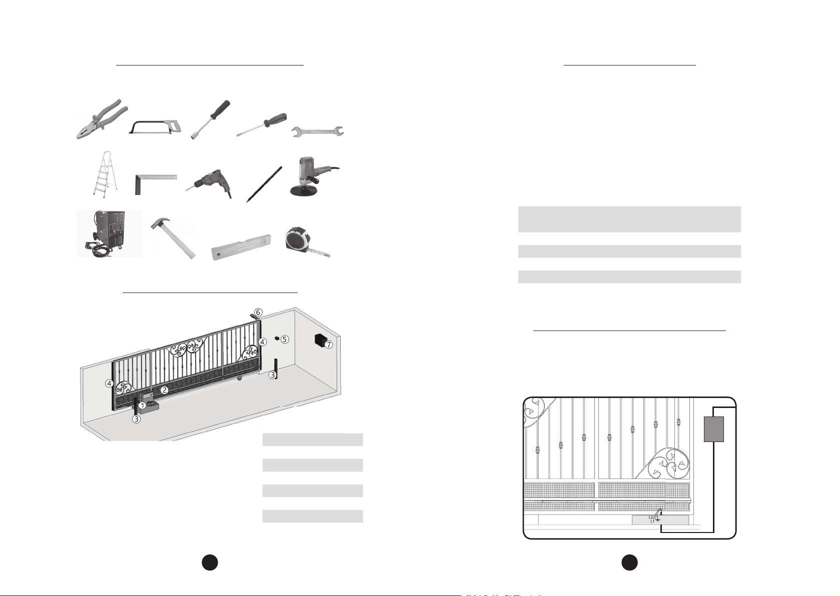
TOOLS REQUIREd FOR INSTALLATION
ELECTRICAL INSTALLATION
Here are some tools required to install the operator:
PLIERS SAWING BOW SOCKET WRENCH SCREWDRIVER NUT WRENCH
LADDER
WELDING MACHINE HAMMER LEVEL TAPE MEASURE
FRAME DRILL PENCIL SANDER
TYPICAL INSTALLATION OVERVIEW
For electrical installation, the network shall contain the following characteristics:
- 230V-50Hz power supply;
The passage of the wiring must be made through conduits between:
- the electrical distribution box and the total disconnect device
- the total disconnect device and the operator supply terminals;
- the control board and the (optional) external pushbutton;
- the control board and the photocells;
The wires used must comply with the local standards. The recommended cable
sizes are listed below:
DZ IND 1.0 BRUSHLESS DC
DZ IND 1.5 BRUSHLESS DC
DZ 2.0 ROBUST BRUSHLESS DC
Power supply 230V 3 x 1,5 mm² 50 m
Photocells 2 x 0,5 mm² 10 m
Safety Edges 2 x 0,5 mm² 10 m
Pushbutton 2 x 0,5 mm² 5 m*
Flashing light 2 x 1 mm² 20 m
*For further distances, please contact technical support.
Cable Section Maximum Lenght
CARE WITH ELECTRICAL INSTALLATION
To avoid damage to the wiring, it is important that all conductors are properly
attached to the operator. Wiring must be done through conduits, passing internally
through the base of the oor, ensuring that none of the wiring conductors are
trapped and damaged.
ITEM DESCRIPTION
1 Gate Operator
2 Rack
3 Photocells
4 Safety Edges
5 Pushbutton
6 Flashing light
7 Power supply 230V
6 7
Page 5
It is mandatory that the
Z12 = 117
Z17 = 132
Z12 = 117
Z17 = 132
ground terminal is connected
to the grounding cable
network.
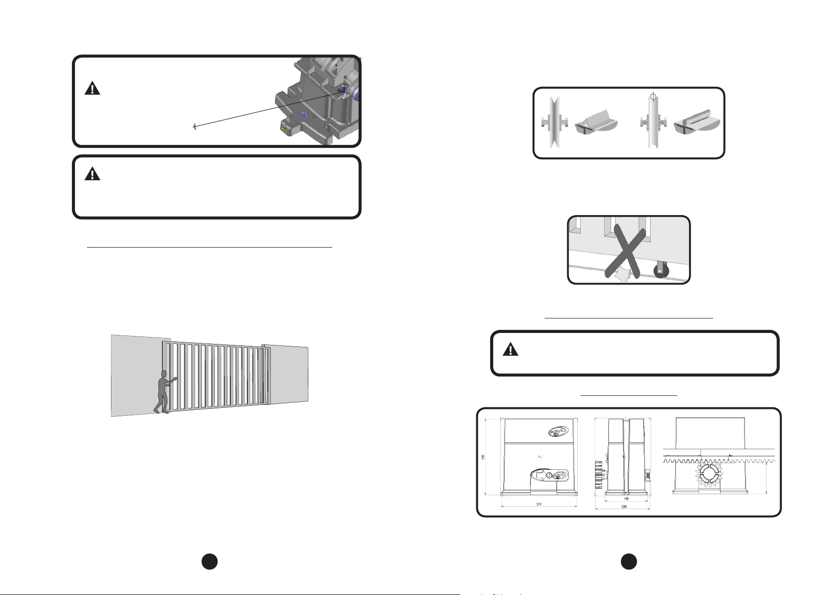
and consequently greater wear. The circular section (Figure B) allows a better
displacement of the gate and less friction for the operator.
FIGURE A FIGURE B
IMPORTANT
The electrical installation must have a residual current (RCD)
device with a rated residual current of 30 mA.
CARE WITH THE GATE bEFORE THE AUTOMATION
Before adapting the machine to the gate, check the gate movement by following
the instructions below:
Step 1: Before installing the operator, check if the gate is in good mechanical
condition, ie opening and closing properly. Open the gate manually and observe
the required e ort. This e ort should be minimal for the entire length of the rail.
Step 2: Close the gate manually and check whether the e ort was the same as the
previous operation.
The gate shall have a sturdy and, as far as possible, non-deformable structure. The
pulleys shall have a diameter suitable to the dimensions of the gate, shall be in
perfect running condition and shall be mounted in such a way that the gate leaf
has stability along all its displacement. We recommend pulleys with a diameter of
at least 120 mm.
The gures below represent the two types of rails and pulleys used. The system
that uses straight section (Figure A - angle bracket) exhibits greater friction
Step 3: Check wether the gate leaf does not jam in the opening and closing
movement. The slide rail of the gate must be perfectly rectilinear, undercut, and clear
of any element or dirt that makes it di cult to slide the pulleys in their entire length.
INSTALLATION OF THE OPERATOR
Before installing the operator, remove all unnecessary cables and
disable any equipment or system connected to the mains.
EQUIPMENT DIMENSIONS
Z12 = 117
Z17 = 132
NOTE: All measurements are in milimeters.
8 9
Page 6
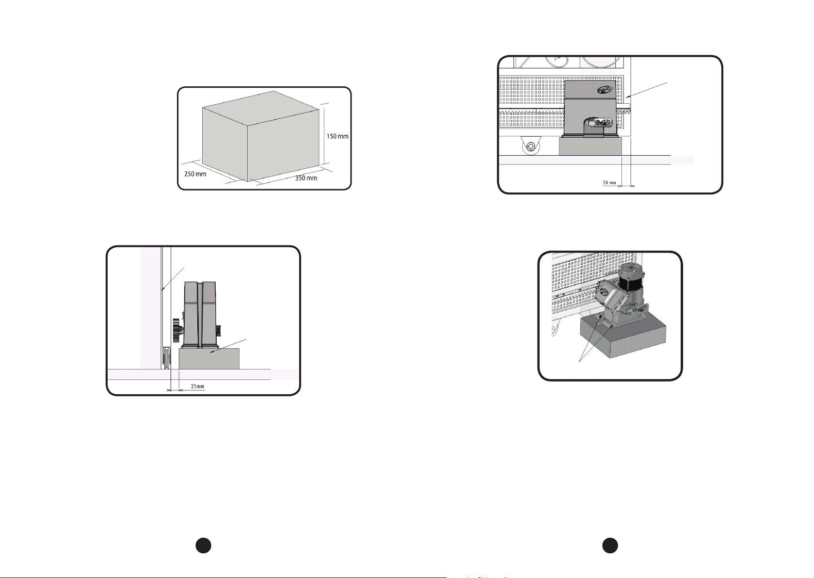
The correct operation of this equipment depends on the instructions in this
manual. To secure the equipment, proceed as follows:
Step 1: Make sure the oor
is rm enough so that the
equipment can be screwed on
a level. If it does not comply
with the requirement, provide
a concrete base, following the
guidelines in the right image:
GATE LEAF
Step 2: The dimensions of the base should be appropriate for the dimensions of
the operator. The concrete base should be at a distance of approximately 25 mm
from the face of the gate leaf.
GATE LEAF
SIDE VIEW
CONCRETE BASE
Step 3: When the conditions are fullled, open the gate and position the operator
near the face of the gate leaf, obeying the 50 mm measurement between the leaf
end and the operator.
Step 4: Pre-align the operator with the gate, positioning the rack over the gear
and pushing the assembly to the gate. Then mark the xing holes in the oor or
concrete base.
MARK THE FIXING HOLES
ON THE FLOOR
Step 5: Drill the holes for fastening. Place the operator aligned to the gate and
insert the 3/8” x 3.3/4” bolts without tightening them. Move the gate, making sure
that it does not lean against the operation during the during its travel. If this occurs,
pull back the operator.
10 11
Page 7
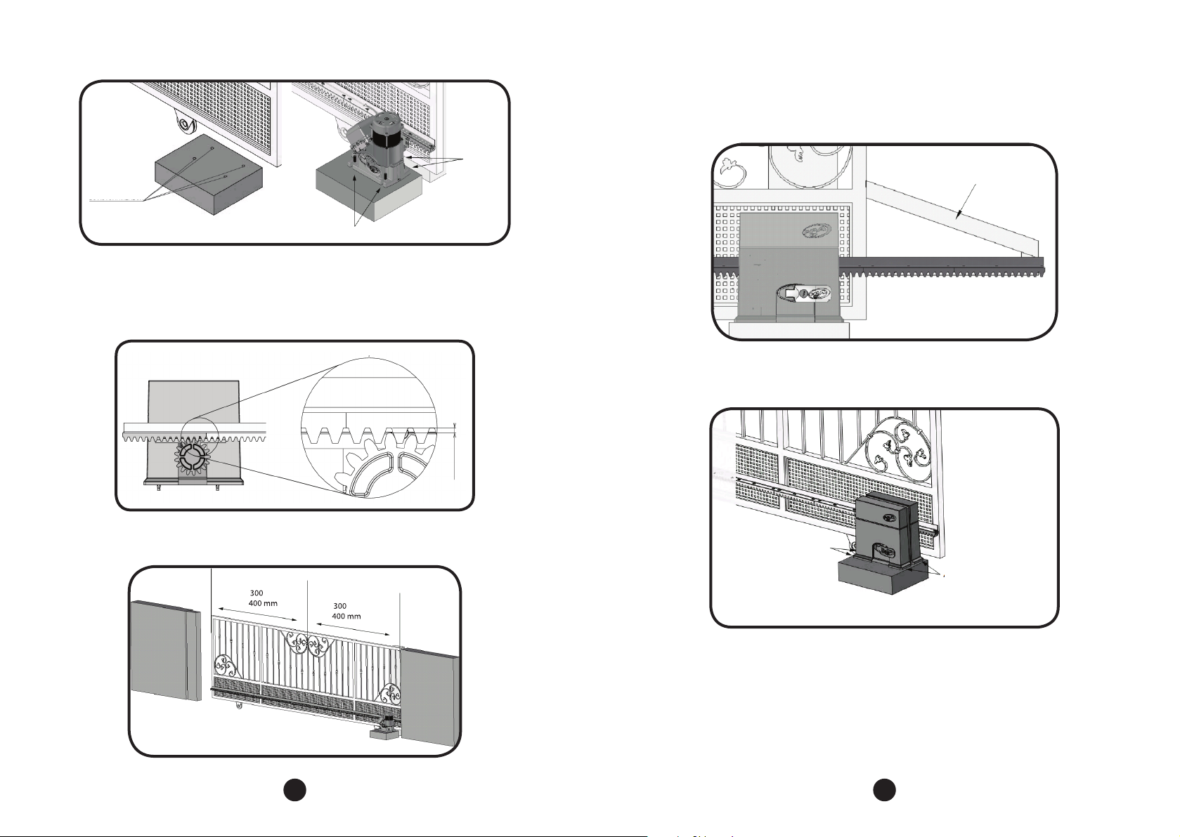
INSERT 2
PARABOLTS
FIXING HOLES OF
THE OPERATOR
INSERT 2 PARABOLTS
Step 6: With the operator unlocked, position the rack bar on the gear and aligned
with the gate.
It is necessary to leave a gap of approximately 2 mm between the top tooth of the
gear and rack bottom tooth.
GAP OF 2mm
Step 8: If the gate leaf is warped, provide shims to ensure alignment of the rack.
There are cases where the rack should pass the length of the gate leaf. In this case,
provide a bracket so the rack teeth will not be skipped when starting the machine.
BRACKET
Step 9: After xing the rack, x the operator to the oor or concrete base by
tightening the bolts.
Step 7: Fix the rack to the entire length of the gate leaf with solder or screw every
300 or 400 mm.
OR
OR
12 13
TIGHTEN COMPLETELY THE
PARABOLTS HEX NUTS TO
FASTEN THE ENGINE.
TIGHTEN COMPLETELY THE
PARABOLTS HEX NUTS TO
FASTEN THE ENGINE.
Page 8
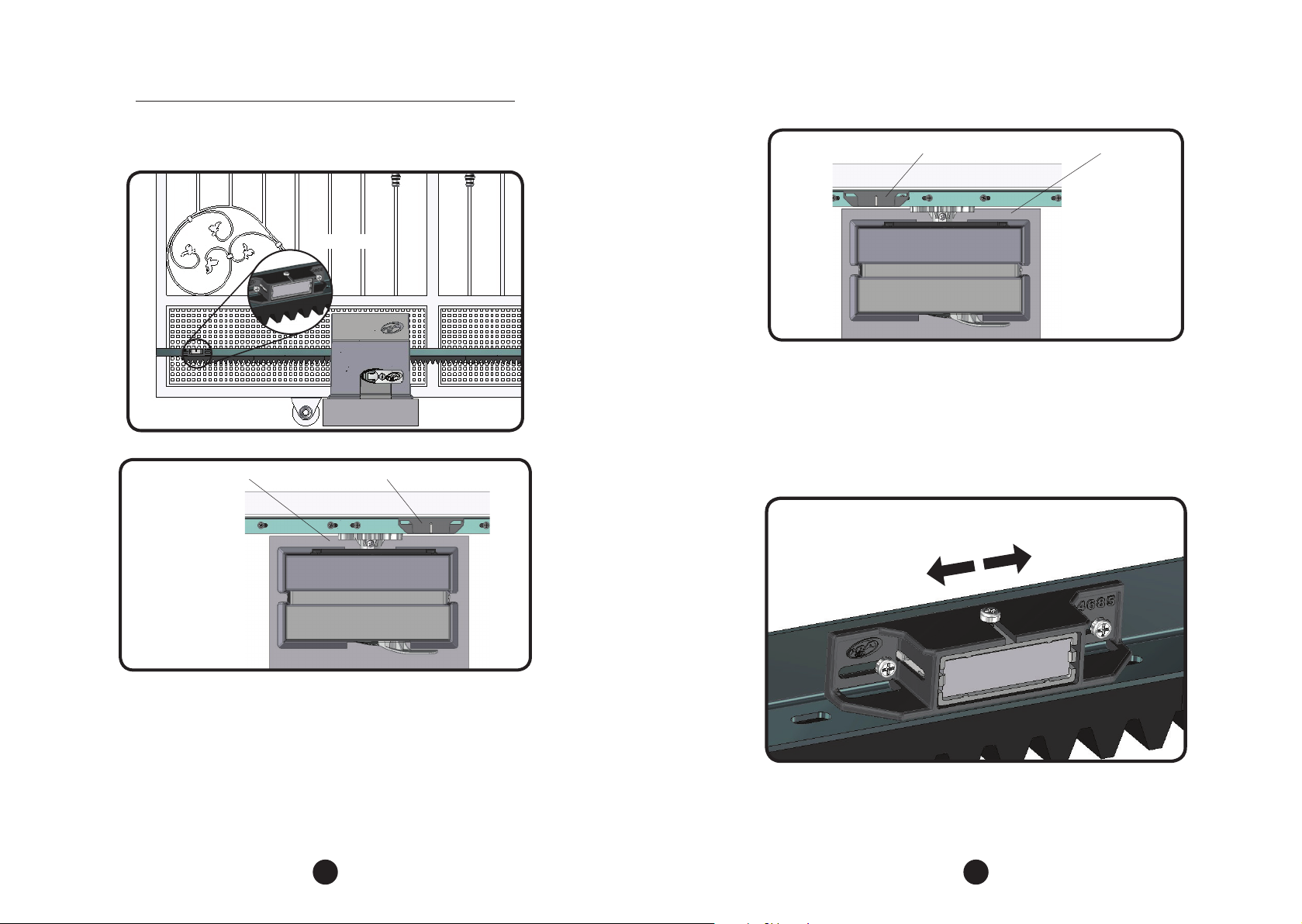
INSTALLATION OF THE ANALOG LIMIT SWITCHES
Step 1: With the gate closed, place the magnet holder on the rack, positioned in
front with the REED of the operator. This magnet will act as a closing limit switch.
MAGNET HOLDER
MAGNET HOLDERREED SUPPORT
Step 2: Fully open the gate and place the other magnet holder on the rack, facing
forward with the operator REED. This magnet will act as an opening limit switch.
MAGNET HOLDER
REED SUPPORT
Step 3: Remove the plastic covers to gain access to the board, then operate the
motor and see if the REEDs are shutting down properly. If necessary, invert the MGS
connector on the control board.
After attaching the magnet holders, make nal adjustments by moving them to
the right or left, depending on the desired setting.
14 15
Page 9
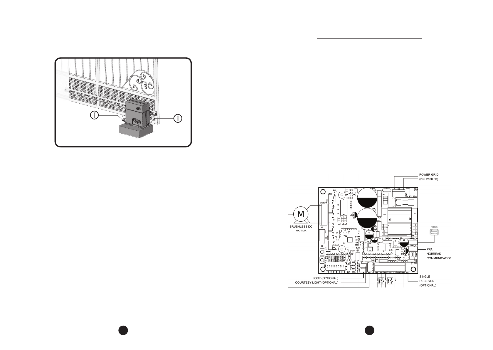
Step 4: To nalize the installation of the operator system, it is mandatory
reposition the cover and screw it with 2 screws PP MS 3,9 x 9,5 mm (already
available on the product).
TRIFLEX CONNECT BRUSHLESS BOARD
The Tri ex Connect Brushless board allows all parameters to be con gured through the
PROG programmer in three languages (Portuguese, English or Spanish) or trough the
mobile app BLUE (In this case, it is necessary to purchase the “BLUE” module from PPA).
It can control all PPA operator models with Brushless motors.
It has an EEProm¹ memory that stores the codes of the Transmitters recorded in
encrypted form. The board is also compatible with Rolling Code Transmitters with
PPA’s own protocol.
System activation can be carried out via remote control through the built-in radio
receiver, a single receiver or any other device that provides a normally open (N.O.)
contact, such as a push button.
Tri ex Connect Brushless is ideal for use with PPA Nobreaks. It has features for
reducing consumption when operating on battery power.
The gate positioning control is done through a PPA patented encoder system
called “Reed Digital”.
Electrical Connections
Electrical connections can be seen in the following diagram:
¹ EEPROM (Electrically-Erasable Programmable Read-Only Memory) is a non-volatile storage chip used in computers and
other devices.
16 17
Page 10
System Power
The mains connection must be made at the L and N input of the power
terminal, AC connector, see gure 1.
NOTE: Before connecting the optional accessories (Electromagnetic
Lock and / or Garage Light / Signal, pushbuttons and etc.), it is advisable
to carry out a general test of machine operation. To do this, simply
press the “+” button to activate the gate travel recognition cycle.
WARNING
The operator input voltage is 230V 50Hz.
Brushless Motor Connection
The three wires of the Brushless motor must be connected to the "MOTOR”.
Encoder “ENC” connection
It is used to connect the encoder, through an appropriate cable, between the
motor and the board. Inside the operator reduction box there are sensors that have
the function of providing direction of travel information and gate position during
operation. Such information is essential for proper operation of the operator.
There are two sensors inside the encoder and each one is represented by the
ECA and ECB LEDs. Each LED lights up according to the position of the disc.
Connection of the electromagnetic lock "LOCK"
If an Electromagnetic Lock (optional) is used, the must be connected to this
connector. The board will recognize the module automatically and a time will be
added to start the opening movement of the operator after the lock is activated.
Courtesy light Connection “LIGHT”
If a courtesy light is used, the “Optional Relay Module” must be connected to this
connector. Courtesy light operation is always enabled. Simply set the desired time
through the DIP switch according to the programming table in this manual.
Separate receiver connection "REC"
A separate receiver can be added to the board via the "REC" connector.
When a command is accepted, the CMD LED (command) is triggered. The ENRF
Jumper must be removed when the single receiver is added to the system in order
to turn o the built-in receiver.
Safety Inputs for Closing and Opening - “SFC” and “SFO”
The SFC input stops the closing movement and reverses the gate.
The SFO input causes an immediate stop (with a short reverse) of the gate opening
movement.
These inputs support safety devices like photocells and safe edges with normally
open “NO”, normally closed “NC” contacts, as well as devices with 8.2 k constant
resistance output.
The safety condition provided by the device(s) is recognized by the control board
so that when there is a variation on this safety condition, the movement stops and
reverses.
It is possible to arrange multiple devices, respecting some conditions, as described
next:
• Multiple NO devices can be connected to each other in parallel without
restriction.
• Multiple NC devices can be connected to each other in series without
restriction.
• Devices with 8.2 k constant resistance output can be connected in parallel;
• It is also possible to combine NO and NC devices in parallel, using an 8.2 k
resistor in series with the NC contact.
IMPORTANT
In order to comply with category 2 or 3 of EN ISO 13849-1, only
devices with 8.2 k constant resistance shall be used.
Photocell should be installed at a height of about 50 cm from the oor (or as
recommended by the manufacturer) and installed so that transmitter and receiver
are aligned with each other. The electrical connection should be made as follows:
Terminal 2: 15V (positive “+”);
Terminal 1: GND (negative “-”);
Terminal 4: SFC (Photocells or Safety Edges on the closing direction);
Terminal 6: SFO (Photocells or Safety Edges on the opening direction).
18 19
Page 11
Pushbutton Connection “PBU”
“PROG” Connection
The board recognizes a button control when the PBU terminal is connected to
the GND, ie a pulse for GND.
Terminal 1: GND (-);
Terminal 4: PBU (Normally Open Contact - N.O.).
Pushbutton Connection for only opening “OPE”
The board recognizes an opening command when the OPE terminal is
connected to the GND, ie a pulse for GND.
Terminal 1: GND (-);
Terminal 5: OPE (Normally Open Contact - N.O.).
Pushbutton Connection only for closing "CLO"
The board acknowledges a closing command when the CLO terminal is
connected to the GND and then released, ie a pulse for GND and then the button
must be released.
This can also be used in access control systems that use photocells or inductive
loops to automatically close the gate or barrier.
Terminal 1: GND (-);
Terminal 6: CLO (Normally Open Contact - N.O.).
ATENTION: The Control Board provides 15 V (maximum
continuous current of 120 mA) for powering photocells and
receivers AND DOES NOT HAVE OVERCURRENT PROTECTION.
If the external optional equipments require more voltage or
current, it will be necessary to use an auxiliary power supply.
External communication connector on control board for use with PROG or BLUE.
“UPS_C” Connection
This connector is the communication between the board and the PPA Nobreaks.
With this connection installed, the board optimizes operation when it is operating
without power from the mains, ie by the batteries.
What is optimized:
1 - The board reduces the power consumption when the engine is switched on
by reducing the work speed, saving up to 50% on battery;
2 - When the control board is in standby, with the gate open or closed, the
motor is o. The control board then sends a command to the PPA Nobreak to turn
o the power control stage and reduce the battery consumption, increasing the
autonomy. With this feature, main power may be disconnected for several hours
without completely draining the battery. Only the RF receiver and the controls
are energized directly by the battery, which allows the control board to receive a
command and only after that the PPA Nobreak reconnects the power control stage
and the operator starts the movement. This system is patented by PPA.
Connection of reed sensors limit switch “MGS”
The control board acknowledges an activated ‘reed’ when the pin corresponding
to it on the MGS pin bar is connected to the GND, i.e., a pulse to the GND.
The only condition that must be followed is that the reed that represents the open
gate must be connected in such a way that the ‘MSO’ LED lights. And the ‘MSC’ LED
must light when the gate is closed.
20 21
Page 12
LOGICAL FUNCTION OF THE SYSTEM FOR GATES
The following table shows the number of blinks for each function:
First operation after installation (gate travel recognition)
When the control board is powered up for the rst time, after the operator being
properly installed, the gate should start an opening movement after an external
command or if the ‘+’ button is pressed.
If instead the gate starts a closing movement, remove the ‘F/R’ jumper to change
the direction of the motor. After removing the jumper the gate will stop. Press
the ‘+’ button again or proceed with an external command. The gate should start
opening. Let the gate reach the opening physical stop or the REED A (magnet limit
switch) is activated. Then, it will automatically reverse the movement direction to
close; let it reach the closing physical stop or activate the closed REED F.
NOTE: The operator can work with encoder (digital) or either encoder
+ reed (hybrid), but cannot work only with a reed.
During the travel recognition only the obstruction of the external
entrapment protection device can reverse the gate movement
direction.
Gate Operation after a power cycle (travel recognized)
After the previous operation, the gate does not need to recognize the travel
again. When the inverter is powered up, the gate simply closes slowly after a
command (‘+’ button or external one), until it reaches the closing physical stop. The
motor will turn o and the operator is ready to use again.
If the photocell is obstructed or the board receives a command during this rst
closing, the gate movement direction will be reversed and, in this case, when the
gate is fully opened the operator is ready to use.
NUMBER OF FLASHES REFERENCE MODEL
1 LIGHTWEIGHT GATE RESIDENCIAL
2 HEAVY GATE INDUSTRIAL
3 BARRIER 3M BARRIER UP TO 3M IN LENGTH
4 BARRIER 6M BARRIER ABOVE 3M TO 6M IN LENGTH
5 NON STOP BARRIER SPECIFIC PPA BARRIER MODEL
The pause before repeating the parameter value is three seconds and the ashes
indicating the parameter value occur every half second, so they are very dierent.
To increase the values, simply press the plus (+) button and to decrease, simply
press the minus (-) button.
When you reach the desired model, return the B/G jumper to the TST position.
Once this is done, the board is ready to operate on the chosen operator model.
NOTE: For the DZ Concominium operator or higher model, use the
“Heavy Gate” parameter in this function.
TST jumper Function
When the TST jumper is removed, the control board enters a mode of operation that
allows to position the operator at any point of its travel path to adjust the limit switches
or to check the mechanical part.
In this operating mode, when the (-) button is pressed, the motor is activated in a
clockwise direction while the button is pressed, when the motor is released, the motor
shuts o, and when the (+) button is pressed, it is activated counterclockwise.
PARAMETERS PROGRAMMING
Operator Model Selection
The board can operate, with the same rmware, on gates and barriers.
To select the desired model, simply remove the TST jumper and close the B/G
(Barrier / Gate) pins. When the function is selected, the “OSC” LED ashes rapidly for
short time interval and then indicates the parameter value.
22 23
Adjustment of other parameters
The control board also has other functions controlled by the DS1 dip switch.
When a function is selected, the ‘OSC’ LED ashes rapidly for a specic period of time
and then indicates the parameter value. When the ‘OSC’ LED ashes each half second
(0.5s), the minimum value is selected; when it is o, an intermediate value is selected
and when it keeps lit, the maximum value is selected.
In order to increase the values, just press the ‘+’ button; to decrease the values, just
press the ‘-’ button when the desired function is selected.
When leaving the function, the ‘OSC’ LED rapidly blinks again for a specic period
of time, and when all DIPs are o it blinks in a one-second interval again.
Page 13
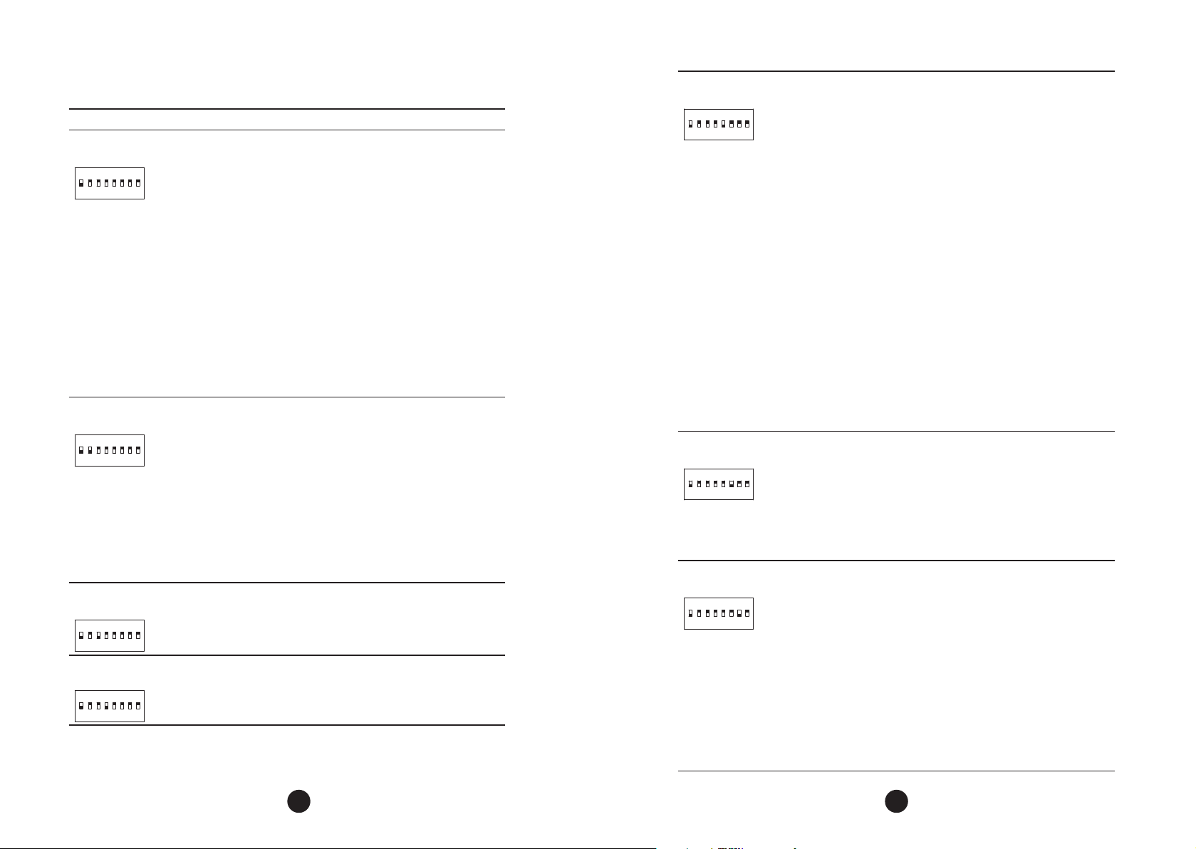
Function Description
“_” or “REC”
(DIP 1)
ON
1
234
FUNCTION SELECTOR / RECORD OR DELETE TRANSMITTERS
(TX)
When combined with other DIPs, it enables the edit of the under-
7
5
8
6
lined parameters.
When only the DIP 1 is activated, the board is ready to record or
delete (TX) transmitters.
Record TX: press the desired transmitter button after you have activated this DIP, note that the OSC LED ashes fast if are receiving the
signal and then press the (+) button on the board to record. Note
that the OSC LED lights up when receive a sinal already recorded
on the board.
Delete: To delete the RF transmitters stored in the memory, press
the Triex (-) button and the (+) button simultaneously for 10 seconds, note that the OSC LED will blink every 1s and after 10s the
LED OSC for the count at that time all recorded transmitters have
been deleted.
“PTA”
(DIP 1 and 2)
ON
1
234
SEMIAUTOMATIC FUNCTION / PAUSE TIME IN THE
AUTOMATIC MODE
Press “+” button for incrementing the pause time.
7
5
8
6
Press “-“ button for decrementing the pause time.
Gate: Increases or decreases time by two seconds (2s) from zero
(0s) two hundred and forty seconds (240s), when the zero value is
selected, the operator becames semiautomatic.
Barrier: Increases or decreases time by one second (1s) from zero (0s)
to two hundred forty seconds (240s), when the zero value is selected
the operator becomes semiautomatic.
“CLS”
(DIP 1 and 3)
ON
1
234
“OLS”
(DIP 1 and 4)
ON
1
234
CLOSING END OF TRAVEL ZONE
Increases or decreases the distance in which the operator starts to
slow down when closing.
7
5
8
6
OPENING END OF TRAVEL ZONE
Increases or decreases the distance in which the operator starts to
slow down when opening.
7
5
8
6
Programming Functions Table:
“GSS”
(DIP 1 and 5)
ON
1
234
7
5
6
“MPA”
(DIP 1 and 6)
ON
1
234
7
5
6
“PCF”
(DIP 1 and 7)
ON
1
234
7
5
6
GATE: HOW TO ADJUST THE GAP BETWEEN GATE AND ITS
MECHANICAL STOP
If necessary, the space between the stop and the gate can be
8
adjusted when the operator completes the closing or opening
cycle. It can be closer or far from the stop.
The minimum value of 0 (LED ashes), increment and decrement
from 1 to the maximum value of 10 (LED lit).
Important: To test the changes, it is necessary to operate the
gate once, so that the operator system performs an opening and
closing cycle.
BARRIER: SET THE BARRIER TO CLOSE AUTOMATICALLY WHEN
ENERGIZED
Press the (-) button to turn o (LED ashing) the function or the (+)
button to activate it (LED on).
When this function is enabled, the barrier automatically initiates
the closing movement after a power-up. If there is any command
to open, for example, FOT, BOT, ABR and etc., the gate initiates an
opening movement.
Also, this function CONFIGURES THE “LIGHT” AND “LOCK” OUTPUTS
TO OPERATE AS “CLOSING BARRIER” AND “OPENING BARRIER”
SIGNALING, RESPECTIVELY.
GATE: HOW TO DECREASE OR INCREASE MOTOR STRENGTH
DURING TRAVEL RECOGNITION.
If necessary, it is possible to decrease the motor force during the travel
recognition, for example, to avoid that the rack bar breaks.
8
It is also possible to increase the strength, if necessary.
Press the ‘+’ button to increase the strength and the ‘-’ button to
decrease it.
The minimum level is 40% (LED blinking) and it is increased by four
levels at a time (4%) up to the maximum 100% level (LED lit).
GATE AND BARRIER: ENABLE PHOTOCELL ‘FOLLOWER MODE’
In some facilities, such as a comdominium, it is necessary that the gate
closes automatically as soon as the vehicle gets out from the gate path.
In order to do so, there must installed a photocell and the “follower” (aka
8
mirrored) function must be enabled.
Press the ‘+’ to enable it and to include the period of time before the
automatic closing.
The minimum value is zero (0 – LED blinking) and it is increased by one
second at a time (1) up to its maximum 60-second value (LED lit).
Example: LED blinking (function disabled). When pressing the
‘+’ button once, the LED is turned o and the “follower” mode is
enabled. The pause time before the automatic closing starts is zero
(0) second. If the button is pressed once more, the pause now is one
(1) second, and so on, up to sixty (60) seconds, when the LED lits.
24 25
Page 14
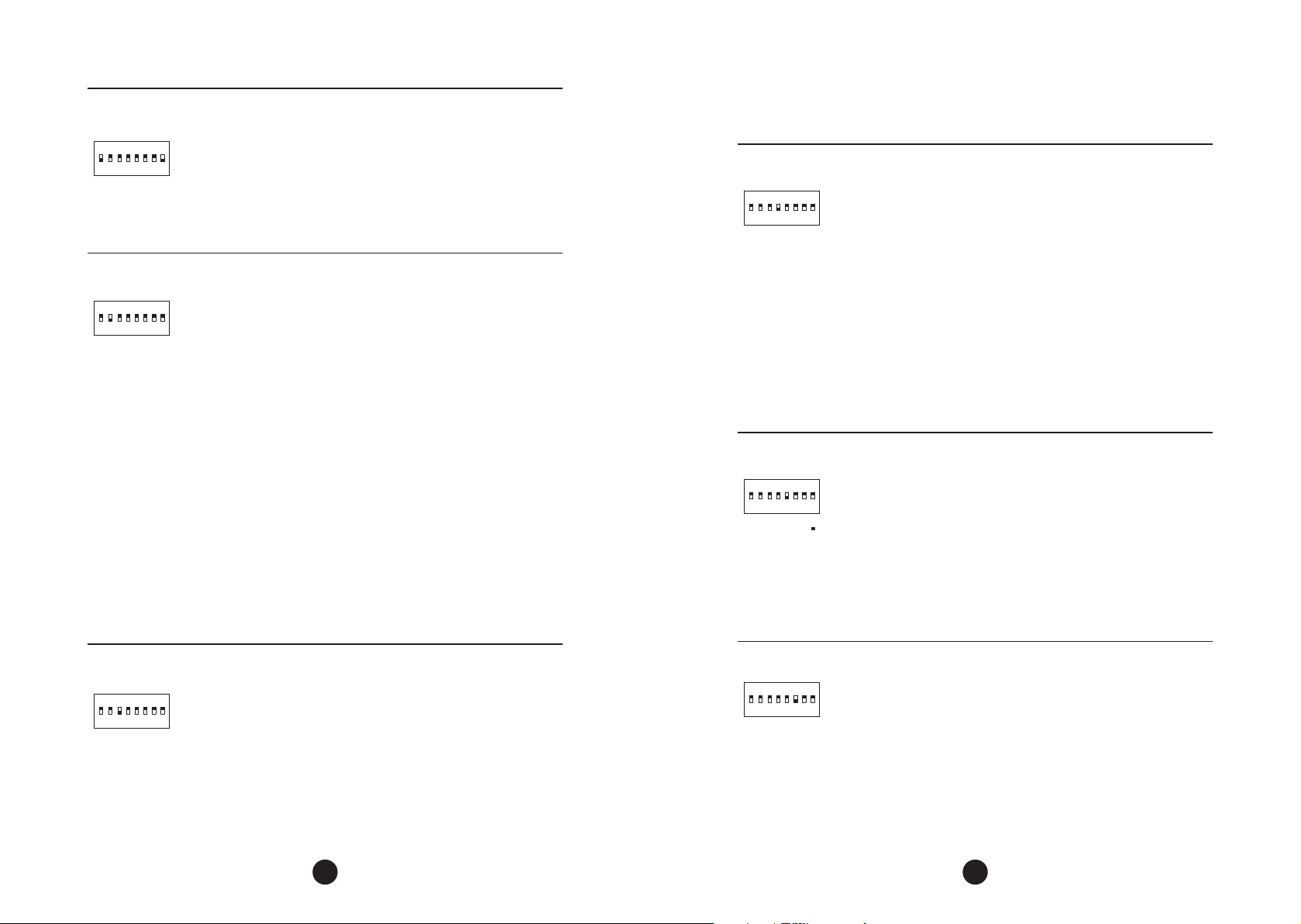
“SF”
(DIP 1 e 8)
ON
5
1
234
“LGT”
(DIP 2)
ON
5
1
234
“SLS”
(DIP 3)
ON
5
1
234
CONFIGURING SAFETY DEVICES
It reads the current state of the SFO and SFC inputs and stores the
value as a safe condition.
To store the safety condition: Press the (+) button and wait for the
OSC led to light up.
7
8
6
IMPORTANT: Before reading the inputs of the safety devices, make
sure that the entire system is installed, connected and that the
devices are NOT actuated.
IMPORTANT: After setup it is extremely important to test the
operation of all safety items that are connected to the operator.
COURTESY LIGHT TIME / PREFLASHING TIME
Selects the time the “LUZ” output is activated after the gate is closed.
The adjustment step is ve seconds (5s), with values from zero (0) to
two hundred and forty seconds (240s). This output is automatically
7
8
6
activated when any key of the DIP switch is triggered or the recognition
process is started.
Note: When using a time between 0 and 235 seconds (or 239, if
programming is via PROG), the “LUZ” output will be activated while
the gate is open, opening and closing. When the closing is complete,
the control unit will decrease the programmed time and turn o the
output when it reaches zero.
When the function value is set to 240s, the “LUZ” output will work in
the “trac light function”, the “LUZ” output indicates that the trac
is released (green light) and the “TRAVA” output indicates that the
trac is blocked (red light). The red light is activated for two seconds
(2 seconds) before the gate starts the closing movement when it is in
automatic mode and remains active throughout the closing until the
gate is fully closed. The green light is activated with the gate opening
and also in the open state.
If the set time is greater than 240s, the “Pre-ashing Time” function
will be enabled and the waiting time before starting the opening
cycle will be adjustable in 5 second steps from 0 to 15s (when the
parameter will be 255s). With the PROG the time can be adjusted
with one second steps (1s). In addition, the PROG display informs you
whether the “trac light” function or the “Pre-ashing Time” function
is enabled.
END OF TRAVEL SPEED
Speed when the gate is next to a travel limit switch (open or closed).
•Switch3on“ON”position(“VFC”);
7
8
6
•Button“(+)”increasethespeed;
•Button“(-)”decreasespeed;
In gates the adjust step is 5Hz, from 15Hz to 30Hz.
In barrier the adjust step is 1Hz, from 4Hz to 20Hz.
ON
1
ON
1
ON
1
“SPD”
(DIP 4)
234
“REV”
(DIP 5)
234
“STG”
(DIP 6)
234
Obs.: The travel recognition speed is equal to the end of travel speed
if it is greater that 20Hz, if it is smaller, the board automatically uses 20
Hz during travel recognition.
GATE: ADJUSTING THE OPENING AND CLOSING SPEED
•SwitchDip4to“ON”(“VFC”)position;
•The“(+)”buttonincreasesthespeed;
7
5
8
6
•The“(-)”buttondecreasesthespeed;
Note: the adjust step is 10Hz, from 60Hz to 180Hz. It is possible to adjust
the opening and closing speeds individually, however this setting is
only available via the PROG keypad, for more information please refer
to the manual of this product. When programming Triex Connect
BRUSHLESS control board via DIP switch, this is not supported.
BARRIERS: ADJUSTING THE OPENING SPEED
•Dip 4 to “ON” (“VEL”);
•“(+)”Buttonincreasesthespeed;
•“(-)”Buttondecreasesthespeed;
Note: The adjust step is 2Hz, from 20Hz to 80Hz.
GATE: DISABLE “STOP” COMMAND DURING OPENING
When the operator is installed in condominiums it may be necessary
to disable the function that stops the gate when receiving a
7
5
8
6
command during the opening.
Press the (-) button to disable (LED blinking) or the (+) button to
enable (LED on).
BARRIER: CHANGE THE CLOSING SPEED
To change the closing speed, press the (-) button to decrease and the
(+) button to increase. The minimum value is 20Hz (OSC LED ashing),
increase by 2Hz to the maximum value of 80Hz (LED OSC on).
GATE: ADJUSTING THE “STRENGTH” OF THE OPERATOR
The operator, by default, has its strength set to the maximum value. It
is possible to decrease it ifnecessary.
7
5
8
6
Press ‘-’ button to decrease the strength and ‘+’ to increase it.
The minimum level is 40% (LED blinking) and the adjust step is (4%)
up to the maximum level, 100% (LED lit).
If the strength is in a very low level, the gate operator won’t work at
full speed.
26 27
Page 15
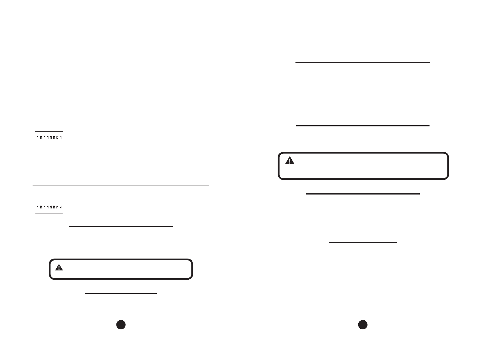
ON
1
234
“STS”
(DIP 7)
5
Press the (-) button to turn o (ashing LED) the open stop function
or the (+) button to activate (LED on); When the (+) button is pressed
again, the blue LED goes o indicating the “delay only” option enabled.
In the “Delay only” option, the gate must abort the command after
another command only if it has not started the movement, ie during
the aperture delay, then it should open without being able to stop.
BARRIER: CONFIGURE “BOT” AS COMMAND ONLY FOR OPENING
When this function is activated, the BOT input becomes an openonly command.
Press the (-) button to turn o (LED ashing) the function or the (+)
button to activate it (LED on).
GATE: START SPEED OF THE GATE
Press the (-) button to decrease and the (+) button to increase.
The minimum value is 20Hz (OSC LED flashing) with an increment
7
8
6
step of 10Hz, up to the 60Hz (LED OSC on) maximum value.
BARRIER: SET THE “LIGHT” AND “LOCK” OUTPUTS TO
OPERATE AS “CLOSING BARRIER” AND “OPENING BARRIER”
SIGNALING, RESPECTIVELY.
Press the button (-) to turn o (LED ash) the function or the button
(+) to enable (LED lit).
at the same time and hold them down until the “OSC” LED lights up. Keep them
pressed until the LED “OSC” ashes. When the buttons are released, the travel is
deleted and the factory settings are applied.
RECORD A RADIO FREQUENCY TRANSMITTER (RF)
In order to record an RF transmitter, slide the dip #1 of the DS1 dip switch to “on”
position, press the button of the transmitter to be recorded and keep it pressed for
at least two seconds. Next, press the ‘+’ button on the triex control board. Note
that before the transmitter has been added, the ‘OSC’ LED blinks rapidly. After it is
recorded, the ‘OSC’ LED keeps on during transmission. Up to 328 transmitters can
be recorded in Fixed Code (CF) mode and 164 transmitters on Rolling Code mode
(see next section).
SELECTION OF RF RECEPTION PROTOCOL (RC/FC)
To select the reception protocol as Fixed Code (FC) mode, simply open the jumper
labeled “RC/ FC”. To select the Rolling Code (RC) mode, simply close the jumper “RC / FC”.
WARNING: Every time this confguration (reception protocol) is
changed, all the recorded remote controls must be erased. For more
information, see the next topic: “Erasing all stored remote controls”.
ON
1
234
“LCK”
(DIP 8)
GATE: Press the button (+) to enable the pulse for a magnetic lock
when the gate is closing (LED ON). Press (-) to turn o (LED ashing).
7
5
8
6
ERASE THE RECOGNIZED GATE TRAVEL
In order to erase the acquired path, simply press both ‘+’ and ‘-’ buttons at the same
time and keep them pressed until ‘OSC’ LED lits. When the buttons are released, the
acquired path is already erased.
NOTE: All keys of the “DIP Switch (DS1)” must be turned o.
APPLY FACTORY DEFAULTS
To return the factory settings to all functions, simply press the “(+)” and “(-)” buttons
28 29
DELETE ALL RF TRANSMITTERS RECORDED
In order to erase all remote controls stored on the board memory, slide the dip #1
of the DS1 dip switch to ‘on’ position, press both ‘-’ and ‘+’ buttons of the control
board at the same time for 10 seconds - observe that the ‘OSC’ LED blinks once
a second and after the 10-second period the LED stops blinking. This means all
added transmitters have been erased.
ANTI-CRUSHING SYSTEM
The anti-crushing feature allows the operator to detect the presence of obstacles in
the gate path. In the normal operating cycle, if an obstacle is detected, the system
will take the following actions:
a) When closing: the gate will be activated in the opening direction.
b) When opening: the engine will shut down and wait for some command to start
the closing.
c) When recognizing the travel: the anti-crushing feature only has the function
of recognizing the opening and closing limits, ie the point of the path where an
obstacle was detected will be interpreted as a limit switch.
Page 16
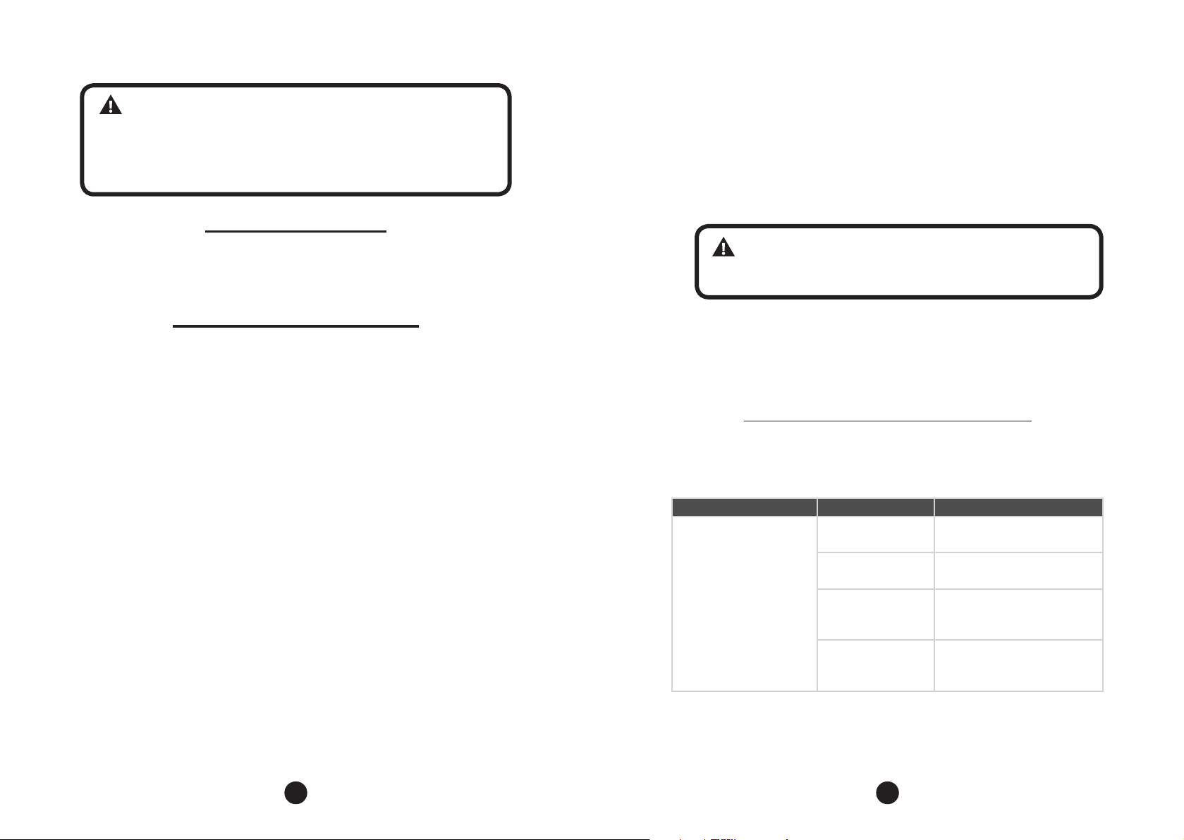
Open limit switch
WARNING: Depending on the installation, this anti-crushing system
is not enough to comply with EN13241, EN12978 and EN12453, and to
avoid accidents with people and animals, requiring the use of photocells
and safety edges.
Even using the inherent anti-crushing system, it is recommended to use
passive edges for better performance and protection.
ENCODER OPERATION TEST
It is possible to test the encoder of the operator by connecting it to the board and
checking if the “ENC” LED is ashing when the operator is moved.
EVENTS AND FAILURES INDICATIONS
Microcontroller operation indication
The main function of the “OSC” LED is to indicate that the controller board is operating.
It ashes with a xed frequency of ~ 1 Hz, since the power is turned on.
Motor over current or short circuit
The “OSC” LED ashes rapidly (in a 0.1- second interval) to warn that the power
stage has tripped due to overcurrent or short circuit in the motor. The board may
operate normally after 10s of the occurrence of the overload.
Overheating
The “END” LED ashes rapidly, in a 0.1-second interval, to warn that the power stage
has tripped due to overheating of the heatsink of the environment. The operator can
only be operated again if the temperature decreases to less than 100ºC.
EEPROM fault
The “OSC” LED ashes twice when Memory is not present.
EEPROM with invalid data
The “END” LED ashes when the gate reaches an open limit switch.
Closed limit switch
The “END” LED is lit when the gate reaches a closed limit switch.
Load in the capacitors
The “BUS” LED indicates that there is load on the power stage capacitors.
WARNING: The power region (capacitor region) of the board
must not be touched while this LED is lit even after the inverter is
disconnected from the electricity grid!
Command
The “CMD” LED on indicates that the control panel is receiving some command
from the digital inputs, such as OPE, CLO, PBU, SFO or SFC.
MAINTENANCE ANd TROUbLESHOOTING
In the table below are found some PROBLEMS - DEFECTS, PROBABLE CAUSES AND
CORRECTIONS - which may occur in the operator. Before any maintenance, it is
necessary to completely disconnect the power grid.
DEFECTS PROBABLE CAUSES CORRECTIONS
A) Power grid o A) Make sure the power grid
is turned on correctly
Motor does not start /
does not move
B) Open/ Burned
fuse
C) Locked gate C) Make sure that there are
B) Replace fuse with the same
specication
no objects blocking the gate
operation
D) Limit switch with
defect.
D) Replace the limit switch
system (analog and / or
digital)
The “OSC” LED ashes three times when Memory is present but it has a content that
the microcontroller does not identify as a Valid Transmitter Code.
30 31
Page 17
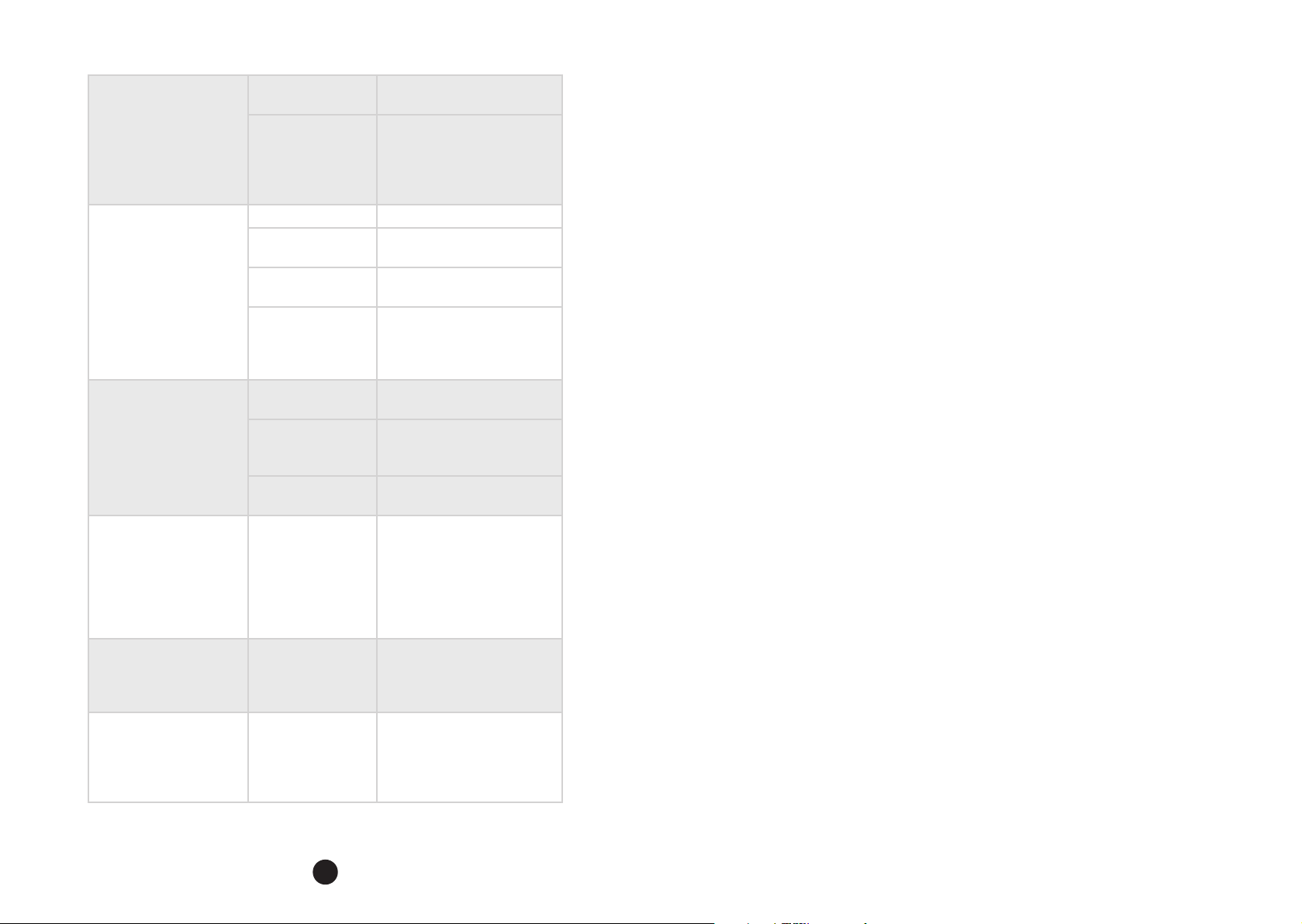
Motor blocked
Electronic board does
not accept command
Motor only turns to one
side
The gate does not
correspond to the path
of the place where
the operator has been
installed (it brakes before
it reaches the stop or
slams when closing).
Gate remains open
and when it receives
commands to open, it
closes.
LED “OSC” ashes
Quickly and the motor
Turns o.
A) Inverted motor
connection
B) Locked gate or
motor
A) Burned fuse A) Replace the fuse
B) Power grid o
(power)
C) Low battery on
the remote control
D) Transmitter
range (remote
control)
A) Inverted motor
wires
B) Inverted limit
switch system
C) Defect in the
commanc board
The recorded path
is dierent from the
place where the
operator has been
installed.
Travel recognizing
was not performed
correctly.
Current sensor
activated. this may
happen when
the motor has a
malfunction.
A) Check the motor wires
B) Manually unlock the
operator and check
individually the gate
movement and the motor
operation
B) Connect the power gird
(power)
C) Check and replace the
battery
D) Check the position of
the receiver antena and, if
necessary, reposition it to
improve the range.
A) Check the motor
B) Invert the limit switch
connector (analog and / or
digital)
C) Replace the board
Press both ‘+’ and ‘-’ buttons
at the
same time and keep them
pressed until ‘OSC’ LED lights
up.
Refer to item: First operation
after installation (gate travel
recognition)
Check the stator resistance.
check the motor current (it
must be less than 3A rms
with 5A rms peak current - 2s
maximum).
32
Page 18
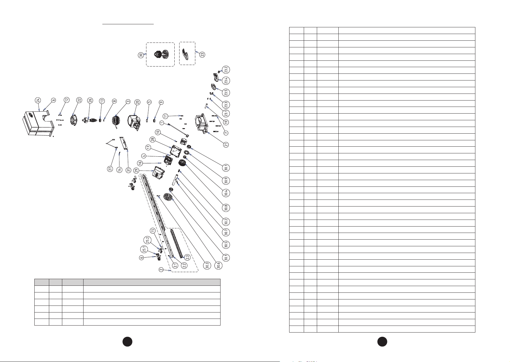
EXPLOdEd VIEW
DZ IND 1.0 BRUSHLESS DC
ITEM QTY CODE PARTS DESCRIPTION (EN)
1 1 A17507 UNIVERSAL ENCODER SET
2 1 A16842 RACK BARS - RESIDENTIAL LINE (1,5 METERS)
2.1 12 C11015 M7 X 15 MM FLANGED SCREW
2.2 1 P03211 RACK BRACKET - RESIDENTIAL LINE
2.3 3 P04067 RACK PIECE - RESIDENTIAL LINE
3 1 A17158 230V 50HZ BRUSHLESS DC STATOR
4 1 A22107 CONTROL BOARD TRIFLEX CONNECT BRUSHLESS DC 230V 50HZ
5 1 C10048 E40 RETAINING RING
6 8 C10254 3,9 X 9,5 PHILIPS SCREW
7 4 C10278 3/8 X 2 ¾" ANCHOR BOLT
8 1 C10285 E17 RETAINING RING
9 1 C10771 6203 ZZ BEARING
10 1 C10778 M5 X 10MM TORX SCREW
11 4 C10779 M5 X 25MM TORX SCREW
12 4 C10781 M5 X 40MM TORX SCREW
13 1 C10883 6203 ZZ NR BEARING
14 1 C10896 M5 X 16MM TORX SCREW
15 2 C11041 7MM X 14MM x 50MM MAGNET
16 4 C20204 3 X 6MM PHILIPS SCREW
17 1 CC00100 3,5x16 SELF-TAPPING SCREW
18 1 P00805 ENCODER COVER
19 1 P01185 UNLOCKING PIN
20 1 P04410 MOTOR UPPER BASE
21 1 P04411 MOTOR UNDER BASE
22 1 P04412 MOTOR UPPER COVER
23 1 P04413 UNLOCKING HANDLE SET
23.1 2 C10896 M5 X 16MM TORX SCREW
23.2 1 C10963 STEEL LOCK 1/2 THREAD ( PAPAIZ 511 + M20 )
23.3 1 P01276 PLASTIC FIXING UNLOCKING HANDLE
23.4 1 P04414 UNLOCKING HANDLE
23.5 1 P04416 ALUMINIUM UNLOCKING BASE
24 1 P04417 ENCLOSURE
25 2 P04685 MAGNET PLASTIC BRACKET
25.1 1 P04686 FIXED BASE FOR MAGNET PLASTIC BRACKET
25.2 1 P04687 ADJUSTABLE BASE FOR MAGNET PLASTIC BRACKET
26 1 P04941 ROTOR SHAFT
27 1 P11912 SET LIMIT
28 1 P05906 CONTROL BOARD BASE
29 1 P05907 CONTROL BOARD COVER
30 1 A17501 Z17 OUTPUT SHAFT SET
30 1 A17502 Z12 OUTPUT SHAFT SET
30.1 2 C10221 6205 ZZ BEARING
30.2 1 C10912 UNLOCKING SPRING
30.3 1 C10921 M6 X 35 PHILIPS SCREW
30.4 1 P00991 FIXING FLANGE ENCODER
30.5 1 P01187 UNLOCKING KEY
30.6 1 P01529 Z17 GEAR - INDUSTRIAL LINE
30.6 1 P01526 Z12 GEAR INDUSTRIAL LINE
30.7 1 P01535 OUTPUT SHAFT INDUSTRIAL LINE
30.8 1 P03110 Z40 WORM WHEEL
30.9 1 P15524 ENCODER DISC - INDUSTRIAL LINE
31 1 P19642 REED BRACKET
34 35
Page 19
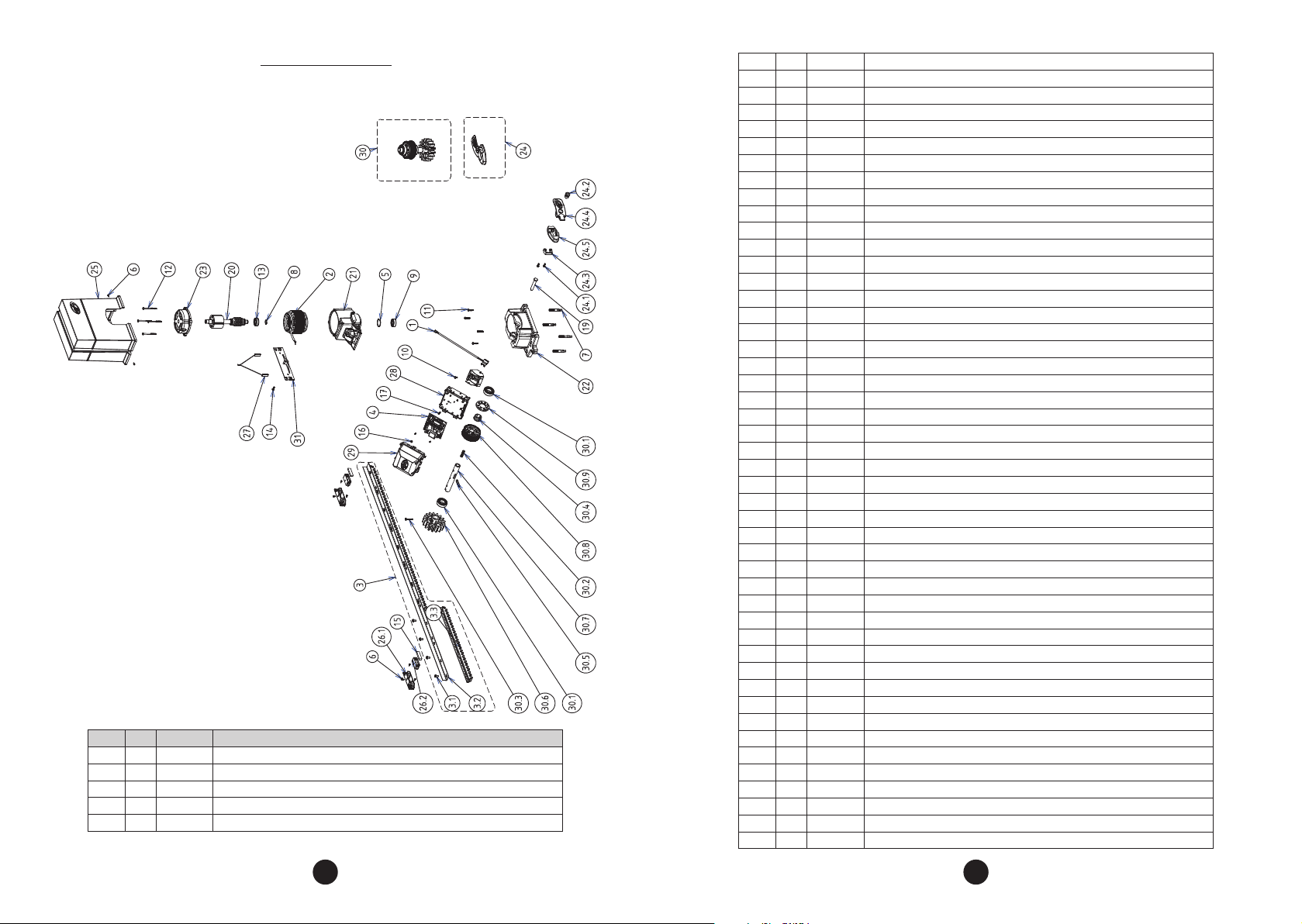
EXPLOdEd VIEW
DZ IND 1.5 BRUSHLESS DC
ITEM QTY CODE PARTS DESCRIPTION (EN)
1 1 A17507 UNIVERSAL ENCODER SET
2 1 A16694 230V 50HZ BRUSHLESS DC STATOR
3 1 A16842 RACK BARS - RESIDENTIAL LINE (1,5 METERS)
3.1 12 C11015 M7 X 15 MM FLANGED SCREW
3.2 1 P03211 RACK BRACKET - RESIDENTIAL LINE
3.3 3 P04067 RACK PIECE - RESIDENTIAL LINE
4 1 A22107 CONTROL BOARD TRIFLEX CONNECT BRUSHLESS DC 230V 50HZ
5 1 C10048 E40 RETAINING RING
6 8 C10254 3,9 X 9,5 PHILIPS SCREW
7 4 C10278 3/8 X 2 ¾" ANCHOR BOLT
8 1 C10285 E17 RETAINING RING
9 1 C10771 6203 ZZ BEARING
10 1 C10778 M5 X 10MM TORX SCREW
11 4 C10779 M5 X 25MM TORX SCREW
12 4 C10859 M5 X 70MM TORX SCREW
13 1 C10883 6203 ZZ NR BEARING
14 1 C10896 M5 X 16MM TORX SCREW
15 2 C11041 7MM X 14MM x 50MM MAGNET
16 4 C20204 3 X 6MM PHILIPS SCREW
17 1 CC00100 3,5x16 SELF-TAPPING SCREW
18 1 P00805 ENCODER COVER
19 1 P01185 UNLOCKING PIN
20 1 P03746 BRUSHLESS DC ROTOR SHAFT
21 1 P04410 MOTOR UPPER BASE
22 1 P04411 MOTOR UNDER BASE
23 1 P04412 MOTOR UPPER COVER
24 1 P04413 UNLOCKING HANDLE SET
24.1 2 C10896 M5 X 16MM TORX SCREW
24.2 1 C10963 STEEL LOCK 1/2 THREAD ( PAPAIZ 511 + M20 )
24.3 1 P01276 PLASTIC FIXING UNLOCKING HANDLE
24.4 1 P04414 UNLOCKING HANDLE
24.5 1 P04416 ALUMINIUM UNLOCKING BASE
25 1 P04417 ENCLOSURE
26 2 P04685 MAGNET PLASTIC BRACKET
26.1 1 P04686 FIXED BASE FOR MAGNET PLASTIC BRACKET
26.2 1 P04687 ADJUSTABLE BASE FOR MAGNET PLASTIC BRACKET
27 1 P11912 SET LIMIT
28 1 P05906 CONTROL BOARD BASE
29 1 P05907 CONTROL BOARD COVER
30 1 A17501 Z17 OUTPUT SHAFT SET
30 1 A17502 Z12 OUTPUT SHAFT SET
30.1 2 C10221 6205 ZZ BEARING
30.2 1 C10912 UNLOCKING SPRING
30.3 1 C10921 M6 X 35 PHILIPS SCREW
30.4 1 P00991 FIXING FLANGE ENCODER
30.5 1 P01187 UNLOCKING KEY
30.6 1 P01529 Z17 GEAR - INDUSTRIAL LINE
30.6 1 P01526 Z12 GEAR INDUSTRIAL LINE
30.7 1 P01535 OUTPUT SHAFT INDUSTRIAL LINE
30.8 1 P03110 Z40 WORM WHEEL
30.9 1 P15524 ENCODER DISC - INDUSTRIAL LINE
31 1 P19642 REED BRACKET
36 37
Page 20
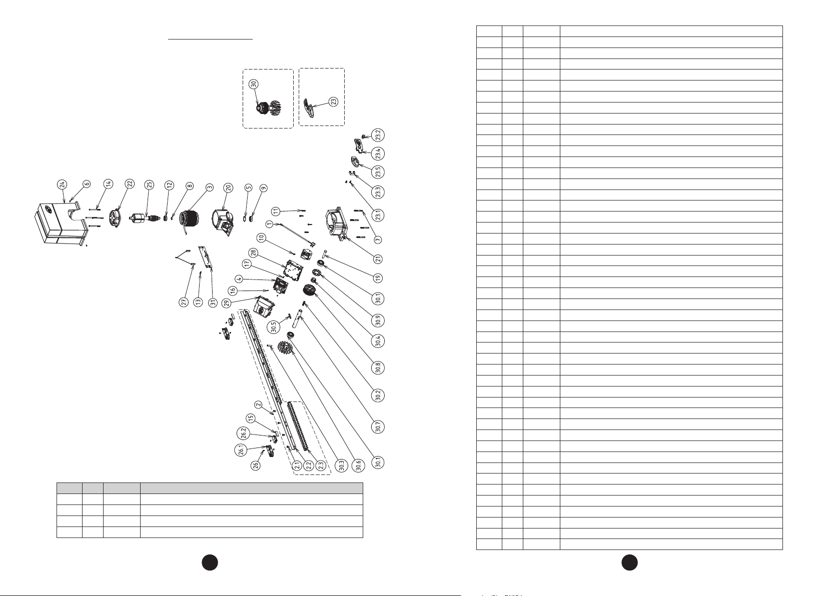
EXPLOdEd VIEW
DZ 2.0 ROBUST BRUSHLESS DC
ITEM QTY CODE PARTS DESCRIPTION (EN)
1 1 A17507 UNIVERSAL ENCODER SET
2 1 A16842 RACK BARS - RESIDENTIAL LINE (1,5 METERS)
2.1 12 C11015 M7 X 15 MM FLANGED SCREW
2.2 1 P03211 RACK BRACKET - RESIDENTIAL LINE
2.3 3 P04067 RACK PIECE - RESIDENTIAL LINE
3 1 A16979 230V 50HZ BRUSHLESS DC STATOR
4 1 A22107 CONTROL BOARD TRIFLEX CONNECT BRUSHLESS DC 230V 50HZ
5 1 C10048 E40 RETAINING RING
6 8 C10254 3,9 X 9,5 PHILIPS SCREW
7 4 C10278 3/8 X 2 ¾" ANCHOR BOLT
8 1 C10285 E17 RETAINING RING
9 1 C10771 6203 ZZ BEARING
10 1 C10778 M5 X 10MM TORX SCREW
11 4 C10779 M5 X 25MM TORX SCREW
12 1 C10883 6203 ZZ NR BEARING
13 1 C10896 M5 X 16MM TORX SCREW
14 4 C11031 M5 X 90MM TORX SCREW
15 2 C11041 7MM X 14MM x 50MM MAGNET
16 4 C20204 3 X 6MM PHILIPS SCREW
17 1 CC00100 3,5x16 SELF-TAPPING SCREW
18 1 P00805 ENCODER COVER
19 1 P01185 UNLOCKING PIN
20 1 P04410 MOTOR UPPER BASE
21 1 P04411 MOTOR UNDER BASE
22 1 P04412 MOTOR UPPER COVER
23 1 P04413 UNLOCKING HANDLE SET
23.1 2 C10896 M5 X 16MM TORX SCREW
23.2 1 C10963 STEEL LOCK 1/2 THREAD ( PAPAIZ 511 + M20 )
23.3 1 P01276 PLASTIC FIXING UNLOCKING HANDLE
23.4 1 P04414 UNLOCKING HANDLE
23.5 1 P04416 ALUMINIUM UNLOCKING BASE
24 1 P04417 ENCLOSURE
25 1 P04424 ROTOR SHAFT
26 2 P04685 MAGNET PLASTIC BRACKET
26.1 1 P04686 FIXED BASE FOR MAGNET PLASTIC BRACKET
26.2 1 P04687 ADJUSTABLE BASE FOR MAGNET PLASTIC BRACKET
27 1 P11912 SET LIMIT
28 1 P05906 CONTROL BOARD BASE
29 1 P05907 CONTROL BOARD COVER
30 1 A17501 Z17 OUTPUT SHAFT SET
30 1 A17502 Z12 OUTPUT SHAFT SET
30.1 2 C10221 6205 ZZ BEARING
30.2 1 C10912 UNLOCKING SPRING
30.3 1 C10921 M6 X 35 PHILIPS SCREW
30.4 1 P00991 FIXING FLANGE ENCODER
30.5 1 P01187 UNLOCKING KEY
30.6 1 P01529 Z17 GEAR - INDUSTRIAL LINE
30.6 1 P01526 Z12 GEAR INDUSTRIAL LINE
30.7 1 P01535 OUTPUT SHAFT INDUSTRIAL LINE
30.8 1 P03110 Z40 WORM WHEEL
30.9 1 P15524 ENCODER DISC - INDUSTRIAL LINE
31 1 P19642 REED BRACKET
38 39
 Loading...