

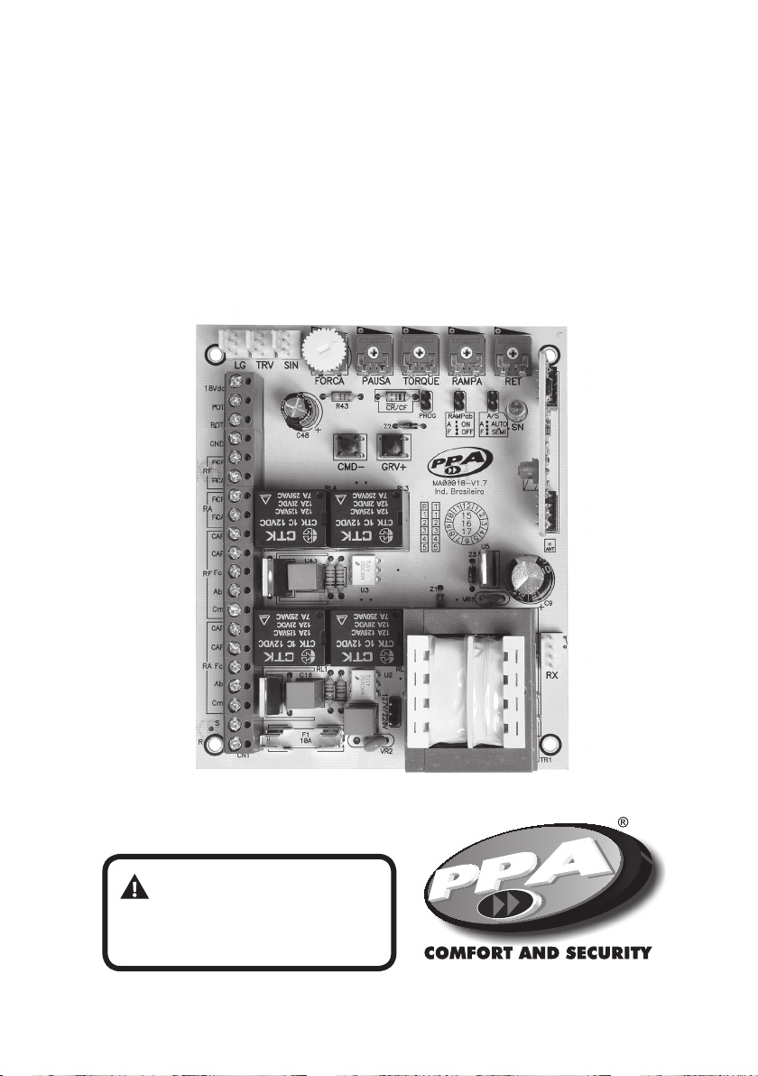
Technical Manual
DUPLA 5T BOARD
WARNING:
Do not use the equipment
without reading the
instruction manual.
Main features
- Analog Limit Switch
- Receptor Module RF 433,92 MHz.
- Code learning:
-160 xe code transmtters (default HT6P20B).
-160 rolling code transmitters (PPA default).
- Input for:
- Photocell (external power suply);
- Buttonhole.
- External RF receptor
- Output for:
- Garage Light Module.
- Lock Module.
- Trac Light Module.
- Deceleration ramp.
- Automatic Memory of route A/F.
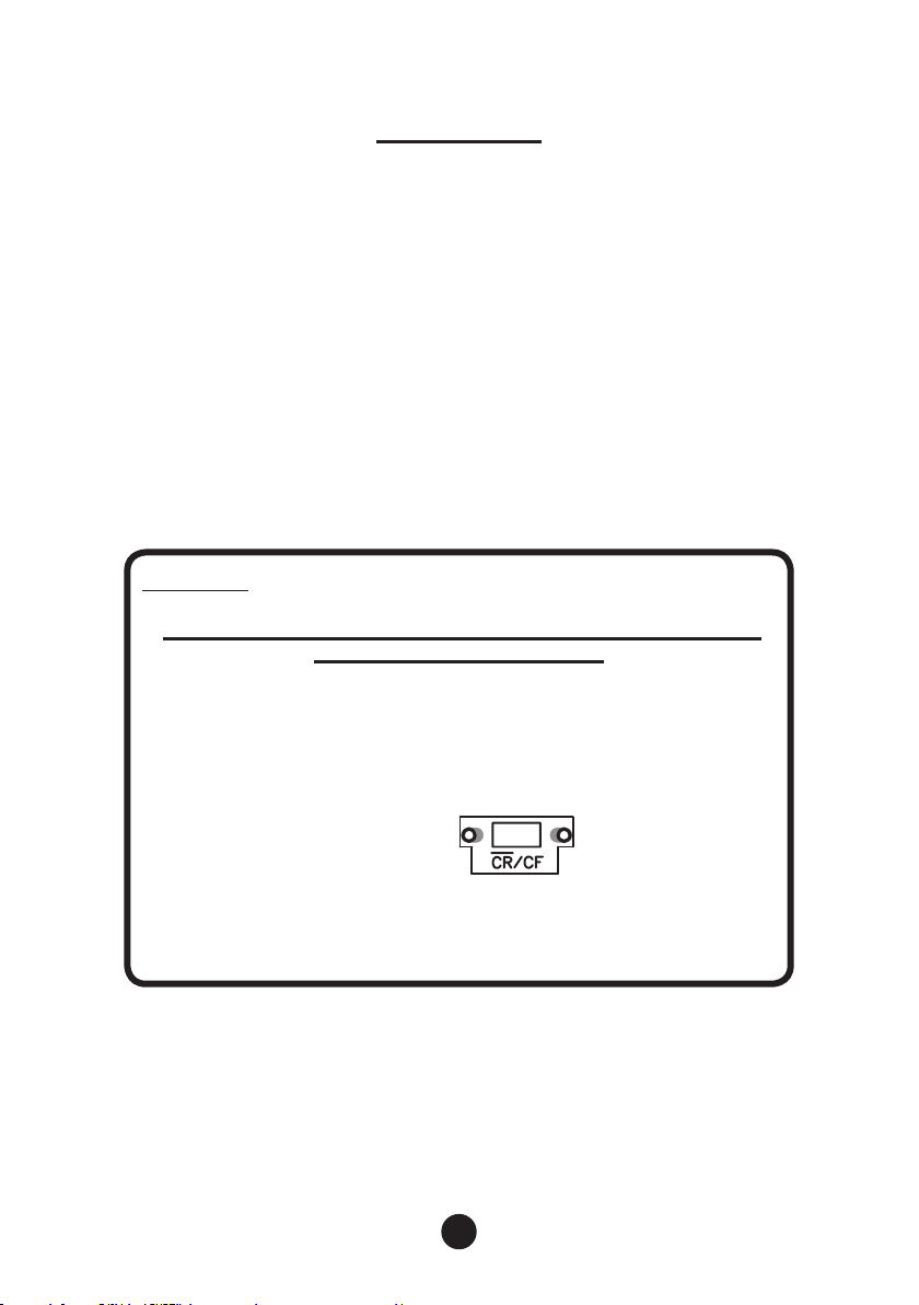
IMPORTANT
first prograMMing after installation or setting
new type of transMitter
This procedure will detele and prepare the memory to receive new
transmitters.
1. Select the type of transmitter.
Conguration:
With resistor = PPA rolling code.
Without resistor = Fixe Code
2. Delete the transmitter (see DELETING TRANSMITTERS).
3. Record new transmitters (see RECORDING TRANSMITTERS).
2

FACTORY DEFAULT #1
OPENING COMMAND #2
DELETING TRANSMITTERS #3
GARAGE LIGHT TIME (LG) #4
BRAKE #5
TRAFFIC LIGHT TIME (SIN) #6
REVERSÃL BY COMMAND #7
MAGNETIC LOCK RAMP #8
OPENING ADJUSTMENT OPENING #9
MAXIMUM TIME COURSE A/F #10
NOMINAL ENGINE TIME #11
LIMIT SWITCH REVERSE BRAKE #12
ELIMINATE BRAKE INERTIA #13
ELIMINATE BRAKE INERTIA TIME #14
PROGRAMMING TABLE
faCtory Default
Restore settings to factory default.
Operation:
1. The gate must be stopped;
2. Close the PROG jumper;
3. Press and release CMD button (1x);
4. Press and release the GRV button to enter the function;
5. GRV button+ to set factory default, or CMD button or remove PROG jumper
(Cancel function).
GARAGE LIGHT 60 scg
BRAKE DRIVE TIME 150,0 msec
TRAFFIC SIGN Turned on
ADJUSTMENT OPENING RAMP 0%
ROUTE A/F (STORED) Turned o
ROUTE A/F PERMITED TIME 2 min
OPENING CONTROL Allowed
REVERSAL BY COMMAND Allowed
MAGNETIC LOCK RAMP 0%
ENGINE NOMINAL TIME 200,0 msec
LIMIT SWITCH REVERSE BRAKE Enabled
ELIMINATE BRAKE INERTIA Enabled
ELIMINATE BRAKE INERTIA TIME 22,0 msec
FACTORY DEFAULT SET UP
3

opening CoMManD
Command permission to the buttonhole or transmitter to operate during the gate
opening route.
Operations:
1. The gate must be stopped;
2. Close the PROG jumper;
3. Press and release the CMD button (2x);
4. Press and release the REC button to enter the function;
5. GRV + button to enable command in the opening, or CMD button to disable
the command in the opening.
6. Finally, remove the PROG jumper.
Deleting transMitters
Delete and initialize the memory to record the new transmitters.
Operations:
1. Gate must be stopped;
2. Close jumper PROG;
3. Press and release the CMD button (3x);
4. Press and release the REC button to enter the function;
5. REC button + to erase the memory of the transmitters, or CMD Button or
Remove jumper PROG (Cancel function).
reCorDing transMitters
PPA default transmitters (xed and rolling code) are supported.
Operations:
1. Gate must be stopped;
2. Close jumper PROG;
3. Press the transmitter button you want to record;
4. SN LED should be ashing fast;
5. Press and release the GRV + button;
6. The SN LED will ash 1 time (recorded button) or ash 3 times (full memory);
7. Release the transmitter button;
8. Go back to step 3 to record new transmitter button;
9. Finally, remove PROG jumper.
4

garage ligHt tiMe (lg)
During opening or closing cycle the gate open or stopped, the relay module will
be connected.
When the central nalize the closing cycle, the relay module will be turned o after
scheduled time.
Values:
0 = Minimum time 1.0 second
1 = 15.0 Split time the 2nd
2 = 30.0 Split time the 2nd
...
17 = Maximum time the 2nd 255.0
Operations:
1. Gate must be stopped;
2. Close jumper PROG;
3. Press and release the CMD button (4x);
4. Press and release the REC button to enter the function;
5. CMD button to decrement value, or REC button + to increase value or remove
jumper PROG (Cancel function).
Signage SN led:
Flash 1x = Releasing CMD and / or GRV + button (command accepted).
Flash fast for 1 second = Rel easing button CMD (command denied to minimum values).
Light for 1 second = Releasing GRV + button (command denied for maximum values).
BraKe
It is triggered to turn o the motor command, or to nd the limit switch analog
sensors.
Values:
0 = on brake.
Time 1 = 0.150 the 2nd
2 = 0.300 time the 2nd
...
17 = Time oscillation 2.55 seconds
5

Operation:
1. Gate must be stopped;
2. Close jumper PROG;
3. Press and release the button CMD (5x);
4. Press and release the REC button to enter the function;
5. CMD button to decrement value, or REC button + to increase value or remove
jumper PROG (Cancel function).
Signage SN led:
Flash 1x = Releasing CMD and / or GRV + button (command accepted).
Flash fast for 1 second = Rel easing button CMD (command denied to minimum values).
Lighted for 1 second = Releasing GRV + button (command denied for maximum values).
traffiC sign tiMe (sin)
During the opening or closing cycle of the gate or when it is stopped, the relay
module will be on or swinging.
When the central nalizes the closing cycle, the relay module will shut down.
Values:
0 = on module.
1 = Time oscillation 0,050 the 2nd
2 = Time oscillation 0,100 the 2nd
...
20 = Time oscillation 1,00 second
Operation:
1. Gate must be stopped;
2. Close jumper PROG;
3. Press and release the button CMD (6x);
4. Press and release the REC button to enter the function;
5. CMD button to decrement value, or REC button + to increase value or remove
jumper PROG (Cancel function).
Signage SN led:
Flash 1x = Releasing CMD and / or GRV + button (command accepted).
Flash fast for 1 second = Releasing button CMD (command denied to minimum values).
Lighted for 1 second = Releasing GRV + button (command denied for maximum values).
6

reVersal By CoMManD
Command permission buttonhole or transmitter operate during the gate closing
path for reversal.
Operation:
1. Gate must be stopped;
2. Close jumper PROG;
3. Press and release the button CMD (7x);
4. Press and release the REC button to enter the function;
5. REC button + to enable rollback command, or CMD button to disable the
rollback command.
6. Finally, remove PROG jumper.
route tHe DriVe MagnetiC loCK
Adjust the closing distance to trigger the magnetic lock.
Values:
10 adjustment levels.
0 = 2%.
...
9 = 20%.
Operation:
1. Gate must be stopped;
2. Close jumper PROG;
3. Press and release the CMD (8x) button to enter the function;
4. Press and release the REC button;
5. CMD button to decrement value, or REC button + to increase value.
6. Finally, remove PROG jumper.
opening aDJusting in tHe raMp
It allows you to individually adjust the distance of the opening ramp to get into
pulsating torque to reduce gate speed.
Values:
17 adjustment levels.
0 = disabled function.
1 = 5% of the total route.
2 = 10% of the total route.
3 = 15% of the total route.
...
16 = 80% of the total route.
7

Operation:
1. Gate must be stopped;
2. Close jumper PROG;
3. Press and release the button CMD (9x) to enter the function;
4. Press and release the REC button;
5. CMD button to decrement value, or REC button + to increase value.
6. Finally, remove PROG jumper.
NOTICE:
If the function is disabled (level 0), the setting of the trimpot RAMP is used to both
sides of opening and closing.
Otherwise, dierent level of 0, the distance from the ramp closing will be dened
by trimpot RAMP and the function setting 9 (Adjust the opening ramp) will be for
the opening cycle.
route perMitteD
Maximum time allowed for the opening/closing cycle of the gate. Setting the A/F
maximum time:
values:
0 = 30 sec
1 = 40 sec
2 = 50 sec
3 = 60 secs
4 = 80 secs
5 = 100 secs
6 = 120 secs
7 = 150 secs
Operation:
1. Gate must be stopped;
2. Close jumper PROG;
3. Press and release the button CMD (10x);
4. Press and release the REC button;
5. CMD button to decrement value, or REC button + to increase value.
6. Finally, remove PROG jumper.
8

noMinal engine tiMe
Time in which the motor is connected at rated voltage during starting.
Values:
20 adjustment levels.
0 = 50.0 msec.
1 = 100.0 msec.
2 = 150.0 msec.
...
19 = 1.0 sec.
Operation:
1. Gate must be stopped;
2. Close jumper PROG;
3. Press and release the button CMD (11x) to enter the function;
4. Press and release the REC button;
5. CMD button to decrement value, or REC button + to increase value.
6. Finally, remove PROG jumper
liMit switCH reVersal BraKe
This feature will ensure that the gate will be completely closed to nd the closing
limit switch.
Operation:
1. Gate must be stopped;
2. Close jumper PROG;
3. Press and release the CMD (12x) button to enter the function;
4. Press and release the REC button;
5. CMD button to enable feature, or GRV + button to disable feature.
6. Finally, remove PROG jumper
eliMinate BraKe inertia
This feature will eliminate the inertia of the gate due to its displacement speed
before entering the ramp region to reduce speed.
Operation:
1. Gate must be stopped;
2. Close jumper PROG;
3. Press and release the button CMD (13x) to enter the function
9

4. Press and release the REC button;
5. CMD button to enable feature, or GRV + button to disable feature.
6. Finally, remove PROG jumper
eliMinate BraKe inertia tiMe
Time in which the brake will eliminate the inertia of the gate due to its displacement
velocity before entering the ramp region to reduce speed.
Values:
20 adjustment levels.
0 = 10.0 msec.
1 = 12,0 msec.
2 = 14.0 msec.
...
19 = 48.0 sec.
Operation:
1. Gate must be stopped;
2. Close jumper PROG;
3. Press and release the button CMD (14x) to enter the function;
4. Press and release the REC button;
5. CMD button to decrement value, or REC button + to increase value.
6. Finally, remove PROG jumper.
autoMatiC Closing (pause)
Semiautomatic Mode (Jumper A / S = Closed)
After complete gate opening cycle, a new command for the closing cycle is
required.
Automatic Mode (Jumper A / S = Open)
After a complete of the gate opening cycle, the programmed PAUSE time will be
decremented every second, and when zero, the closing cycle will start.
Clockwise = shorten time. (Minimum = 1sec)
Counter-clockwise = increase time. (Maximum = 4min)
10

Deleting route
Operation:
1. Gate must be stopped;
2. PROG jumper must be open and
3. Keeping pressing the REC button + for 3.0 seconds; SN led will turn on and o
signaling that performed the operation.
triMpot aDJustMent of eleCtroniC ClutCH
For the use of this security sensor device to be eective, do the following:
- After the proper installation of the operator at the gate, adjust the electronic
clutch so that the force is the minimum necessary to move the gate leaf throughout
its route, opening and closing.
Adjusting the force required during the gate movement.
Scale trimpot = 20 levels.
Clockwise = lower strength.
Anticlockwise = increase strength.
triMpot aDJustMent of pulsating torQue
This setting will slow the gate when your route is within the deceleration ramp
region dened by RAMP trimpot.
If the ramp is disabled by RAMP trimpot, the pulsating torque will be dead.
Scale trimpot = 34 levels.
Clockwise = reduce pulsating torque.
Counter-clockwise = increase pulsating torque.
triMpot aDJustMent of opening anD Closing raMp
It will adjust the distance of deceleration of the limit switch ramps of opening and
closing cycle, in order to decrease the speed of the gate.
Scale trimpot = 0% to 80% of the stored route.
Clockwise = lower the ramp.
Counter-clockwise = increase the ramp.
11

triMpot setting tHe Delay tiMe
If closing is adjusted at minimum, the delay time will be canceled and the engine
will be triggered simultaneously; otherwise, the RETA engine will rst be activated
and after time set by the trimpot RETF engine will be connected. If opening is set
to the minimum, delay time will be canceled and the engine will be triggered
simultaneously; otherwise, the RETF engine will be turned on rst and after time of
1.0 sec the RETA engine will turn on and if the sensor is released FCF_RETF.
Minimum time = 1.0 sec.
Maximum time = 7.0 sec.
iMpotants tips
SETTING WITH RAMP DECELERATION AND SOFT STOP:
After mechanical installation, with the limit switch properly installed and gates in
the middle of the route.
1. Adjust trimpot strength 1/2 turn.
2. Insert jumper A/S (semiautomatic)
3. Trimpot torque at a minimum.
4. Trimpot ramp close to 1/4 turn to a minimum.
5. Trimpot RET 1/4 turn to a minimum.
6. Delete route as item CLEARNING ROUTE.
7. After command (CMD) the gates will open by the limit switch without ramp
and after another command will close by the limit switch without ramp
and note that for each gate to complete the cycle the SN LED will ash fast,
indicating that the route A / F was memorized for each leaf.
8. After this initial memorizing process, the gates will get in ramp mode to soft stop.
12

ConneCtion sCHeMe
RELAY
RELAY
RELAY
MODULE
MODULE
MODULE
ENGINE
ENGINE
BUTTONHOLE
ENGINE
STARTING
CAPACITOR
ENGINE
STARTING
CAPACITOR
BLACK / RED
RED / BLACK
YELLOW
BLACK / RED
RED / BLACK
YELLOW
INCORPORATED
RP RECEPTOR
433,92 MHZ
SEPARATED
RP RECEPTOR
13

www.ppa.com.br
+55 14 3407-1000
Av. Dr. Labieno da Costa Machado, 3526 - Distrito Industrial - CEP 17400-000 - Garça - SP - Brasil
MOTOPPAR INDÚSTRIA E COMÉRCIO DE AUTOMATIZADORES LTDA.
 Loading...