

Page 1
Adhesive
Item
1.
2.
3.
4.
5.
6.
8.
9.
10.
11.
12.
13.
WLAN-A0042
Packing Check List
Description Quantity
WLAN-A0042 enclosure with integrated 23dBi antenna 1
Stand-off pillars 6
M6 x 16mm Bolt – SS 4
M6 external star washer – SS 4
No.6 x 9.5mm - Self Tapping Screws – Galv. 6
M4 - Washers, Flat SS (Inside enclosure) 6
Ethernet gland with accessories 1
Universal Bracket (Aluminium) 1
M6 x 90mm U-Bolt SS 1
Econo bracket 1
M6 Flat Washer SS 4
M6 Nut SS 4
WLAN-A0042 (standard version)
Universal Bracket Kit BRKT-009
Installation Instructions
Installing Electronics
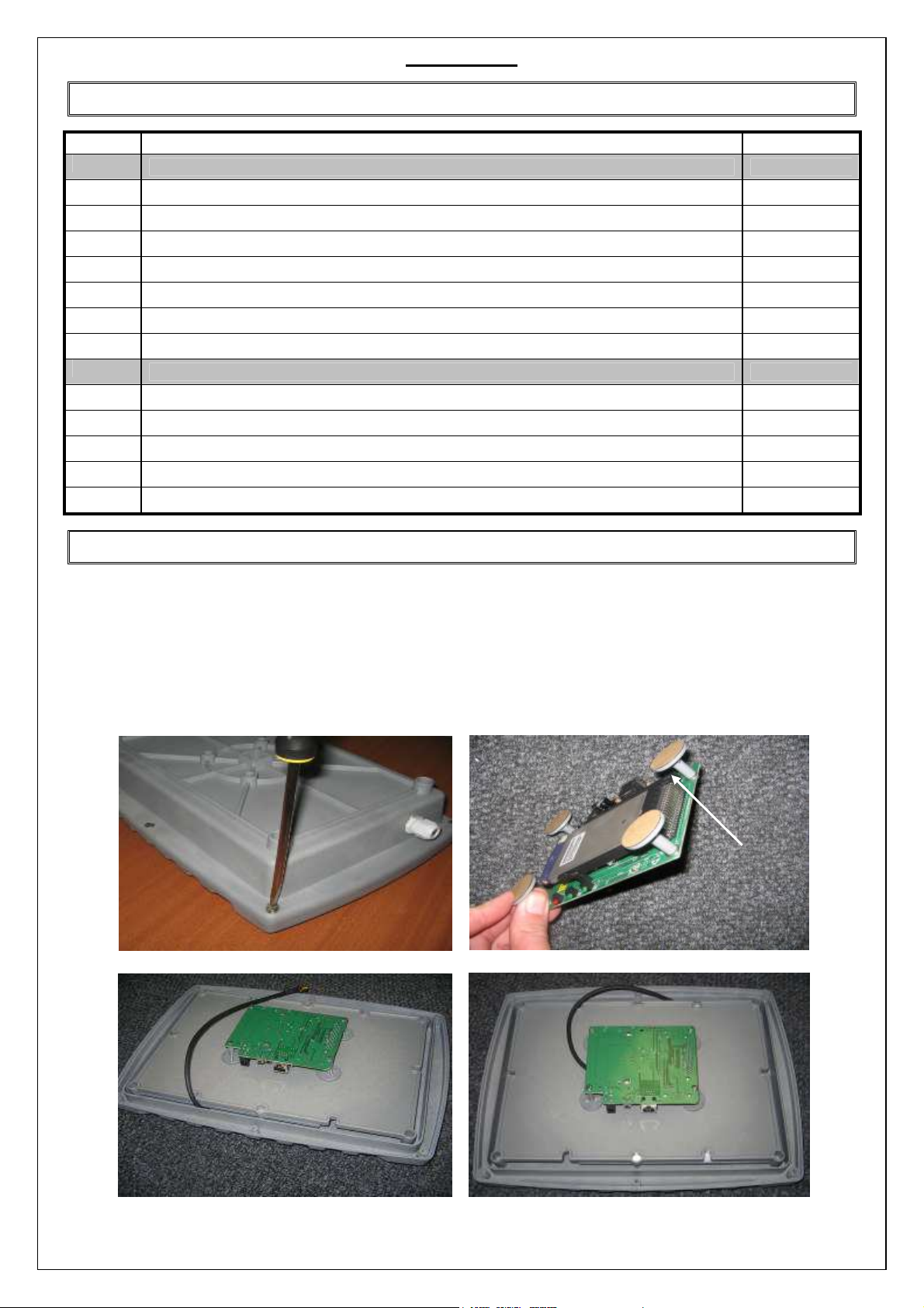
1. Unscrew the back of the enclosure and carefully lift off the lid containing the integrated antenna (refer to figure 1).
2. Use the provided screws and washers (items 5 and 6) to secure the stand-off pillars to the electronics you wish to install. Be
sure that the height of electronics and pillars does not exceed 40mm (refer to figure 2).
3. Peel off the adhesive backing paper from the base of the pillars and secure the pillars to the back of the lid (refer to figure 3).
Ensure that the electronics is located such that the antenna cable can be connected easily.
4. Connect the antenna to the electronics either directly with the SMA(f) connector of by means of an adaptor cable (not
provided) as necessary (refer to figure 4).
backing
paper
Figure 1. Unscrew enclosure.
Figure 2. Secure the stand-off pillars.
Figure 3. Attach electronics to back of lid Figure 4. Connect the antenna to the electronics
WLAN-A0042_PCL V5 0.doc Version: 5.0
Page 2
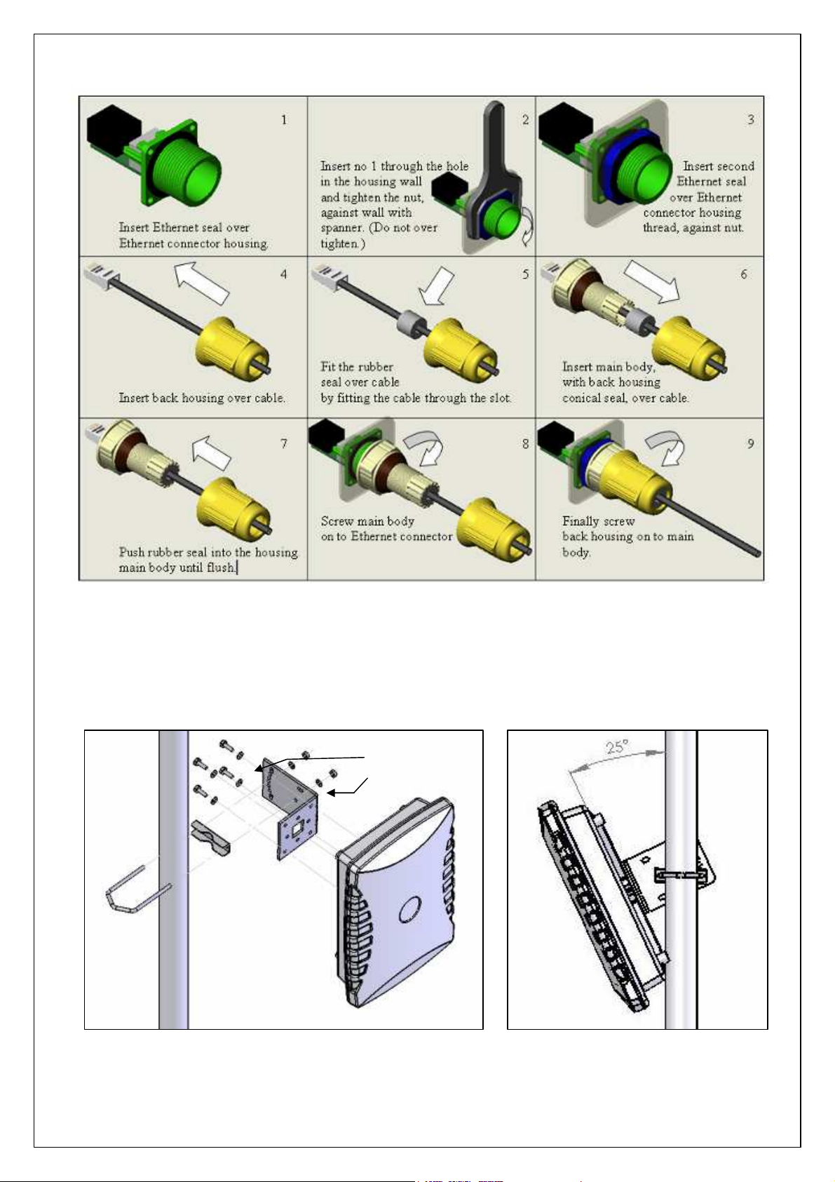
Installing CAT-5 cable
Mounting the enclosure
1. The enclosure can be mounted for either vertical or horizontal polarisation. Refer to polatisation sticker on the back of the
enclosure.
2. Attach the L bracket to the antenna by means of the four M6 x 16mm bolts provided. The figure 6 illustrates this for vertical
polarisation.
3. Attach the enclosure to a mast (diameter 40-50mm) using the Econo-bracket assembly as shown in figure 6.
4. The Econo-bracket can be mounted through different holes to achieve the desired tilt angle of the antenna. (see figure 7).
Star Washers
Flat Washer
Figure 6. Mast mounting
WLAN-A0042_PCL V5 0.doc Version: 5.0
Figure 7. Setting tilt angle
 Loading...