

Powtran PI76007800, PI7600, PI7800 User Manual

Foreword
CONTENTS
Thank you very much for purchasing PI7800,PI7600 Family Frequency
Inverters. This family is designed based on the experience of
POWTRAN Company in the professional manufacture and sale of the
products, and suitable for general-purpose machine, fan/pump drive,
high frequency drive and heavy load machine.
This User’s Manual provides the users with the instructions on the
installation, parameter setting, fault diagnosis, routine maintenance and
necessary precautions. Please read the Manual carefully before the
installation of the product in order to ensure that it can be correctly
installed and operated.
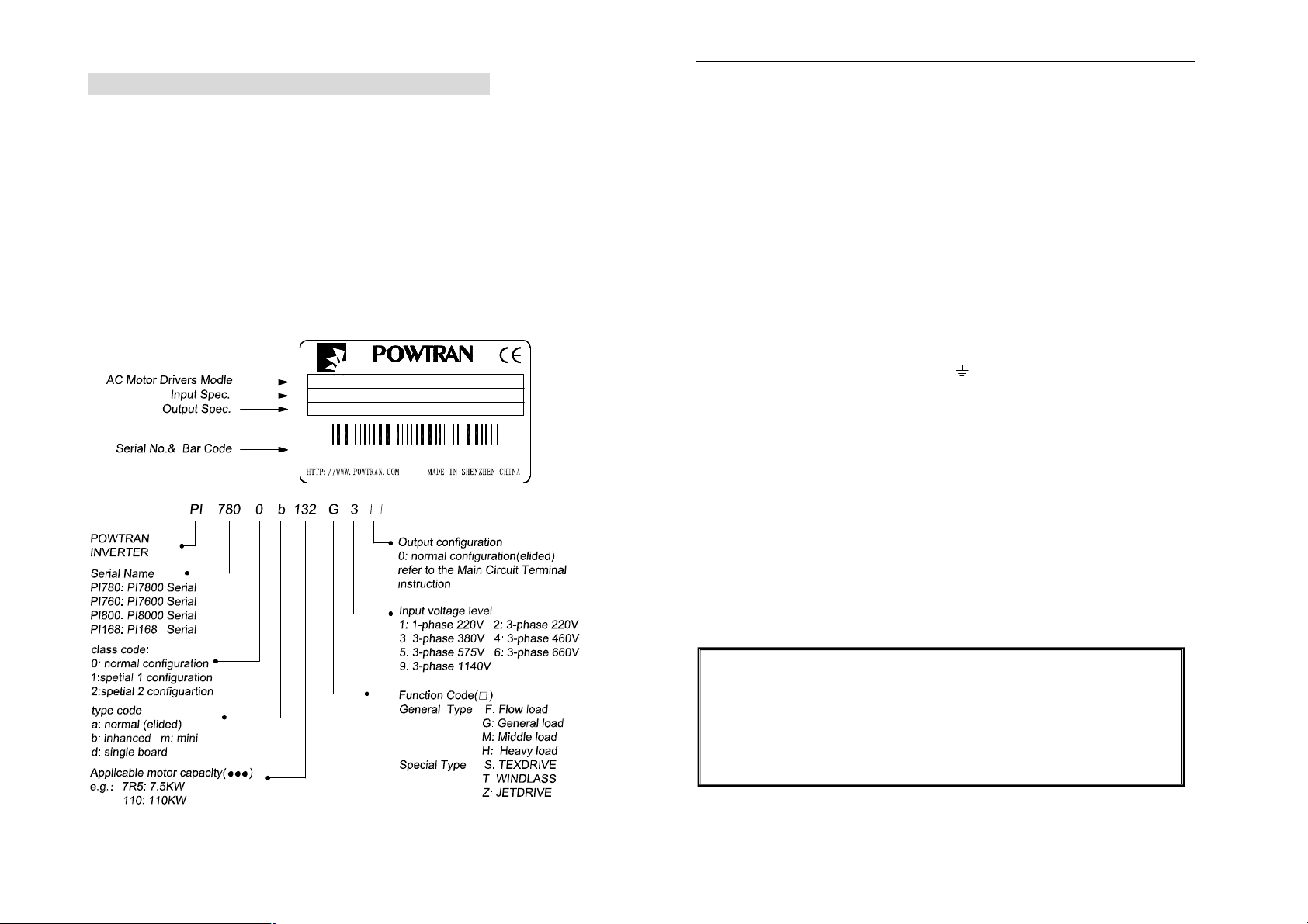
This User’s Manual includes PI7800,PI7600, the general purpose
control and special purpose control . The general purpose control ha
F,G ,M and H; The special purpose control has S,T and Z:
F: FLOW LOAD
G:GENERAL LOAD
M: MEIDDLE LOAD
H: HEAVY LOAD.
S: TEXDRIVE.
T: WINDLASS.
Z: JETDRIVE.
Please contact the local dealers or directly contact our company.
Please keep this user’s manual in good condition, for it will be helpful to
the repair, maintenance, and applications in the future.
For information about other product, please visit our website:
http://www.powtran.com.
Section I. Inspection and Safety Precautions.........................1
Section II. Installation & Standby Circuit................................3
Section III. Operating keyboard..........................................14
Section IV. Test running....................................................19
Section V. Function parameter table...................................21
Section VI. Function Parameter Description..........................34
Section VII. Fault Diagnosis and Solutions.............................88
Section VIII. Standard Specifications.....................................90
Section IX. Maintenance.................................................103
Section X. Options........................................................105
Appendix 1. PI7000 RS485 communication protocol...............109
Appendix 2. PG Instruction...............................................120
Appendix 3. Converter water supply controller instruction ........123
SECTION I. INSPECTION AND SAFETY PRECAUTIONS
Section I. Inspection and Safety Precautions
POWTRAN PI7800/7600 frequency inverters have been tested and inspected
before leaving the manufacturer. Before unpacking the product, please check if
its package is damaged due to careless transportation, and if the specifications
and type of the product complies with the order. Please contact the supplier of
POWTRAN products if any problems are found.
1-1. Inspection after Unpacking
※ Inspect that the contents are complete (one PI7000/7100 frequency
inverter, one Operation Manual).
※ Check the nameplate on the side of the frequency inverter to ensure that
the product you have received is right the one you ordered.
Instructions on name plate: (giving 132kW/380V as example)
TYPE:
SOURCE:
OUTPUT:
POWTRAN TECHNOLOGY CO.,LTD.
Model designation:
PI7800 132G3
3φ 380V 50-60Hz
132KW 250A 0.00-800.0Hz
Z0501A00001
the frequency inverter.
※ Fix and lock the panel before supplying power so as to avoid the danger
caused by the poor capacity or other components inside the inverter.
※ After the power supply is switched on, do not perform wiring or check, etc.
※ Don’t touch the circuit boards or its parts or components in the inverter
when it is powered, so as to avoid danger of electric shock.
※ If the power supply is switched off, do not touch the PCB or other parts
inside the inverter within 5 minutes after the keyboard indicator lamp goes
off, and you must check by using the instrument that the inverter has
completely discharged all its capacity before you start to work inside the
inverter. Otherwise, there will be the danger of electric shock.
※ The static electricity in human body will cause serious damage to the MOS
field effect transistor in the inverter. Please keep your hands away from the
PCB, IGBT and other internal parts before taking actions to prevent static
electricity. Otherwise, faults may be caused.
※ In use, the earthing terminal (E or ) of the frequency inverter must be
grounded to the earthing connections correctly and securely according to
the national electrical safety specifications and other applicable standards.
※ Please don’t shut off the unit by turning off the power supply. Turn off the
power supply after the motor has stopped its operation.
※ Meet CE standard with EMI filter.
1-3. Application
※ Powtran inverter is generally applied to 3 phase AC asynchronism motors.
※ Powtran inverter is applied to the admisive occasion, the occasion where is
not admissive may lead to fire, electric shock, explosion and so on.
※ If the inverter seizes up when it is applied to the equipment which may lead
danger (e.g. lift tools of transportation, aviation system, saftety equipment,
etc), it should be managed carefully. Do inquire the factory when it
happens.
1-2. Safety Precautions
※ Never connect the A.C. power supply to the output terminals (U, V, W) of
1
Only the well-trained personnel are allowed to use this
unit, and such personnel must read through the parts of this
manual relating to the safety, installation, operation and
maintenance before using the unit. The safe operation of this
unit depends on correct transport, installation, operation and
maintenance!
2
SECTION II. INSTALLATION & STANDBY CIRCUIT
Section II. Installation & Standby Circuit
2-1. Conditions for Use
1) Ambient temperature -10℃~40℃.
2) Avoid electromagnetic interference and keep the unit away from the
interference source.
3) Prevent dropping water, steam, dust, powder, cotton fiber or fine metal
powder from entering it.
4) Prevent oil, salt and corrosive gas from entering it.
5) Avoid vibration.
6) Avoid high temperature and moisture and avoid being wetted due to raining,
with the humidity below 90%RH (not dewing).
7) Prohibit the use in the dangerous environment where inflammable or
combustible or explosive gas, liquid or solid exists.
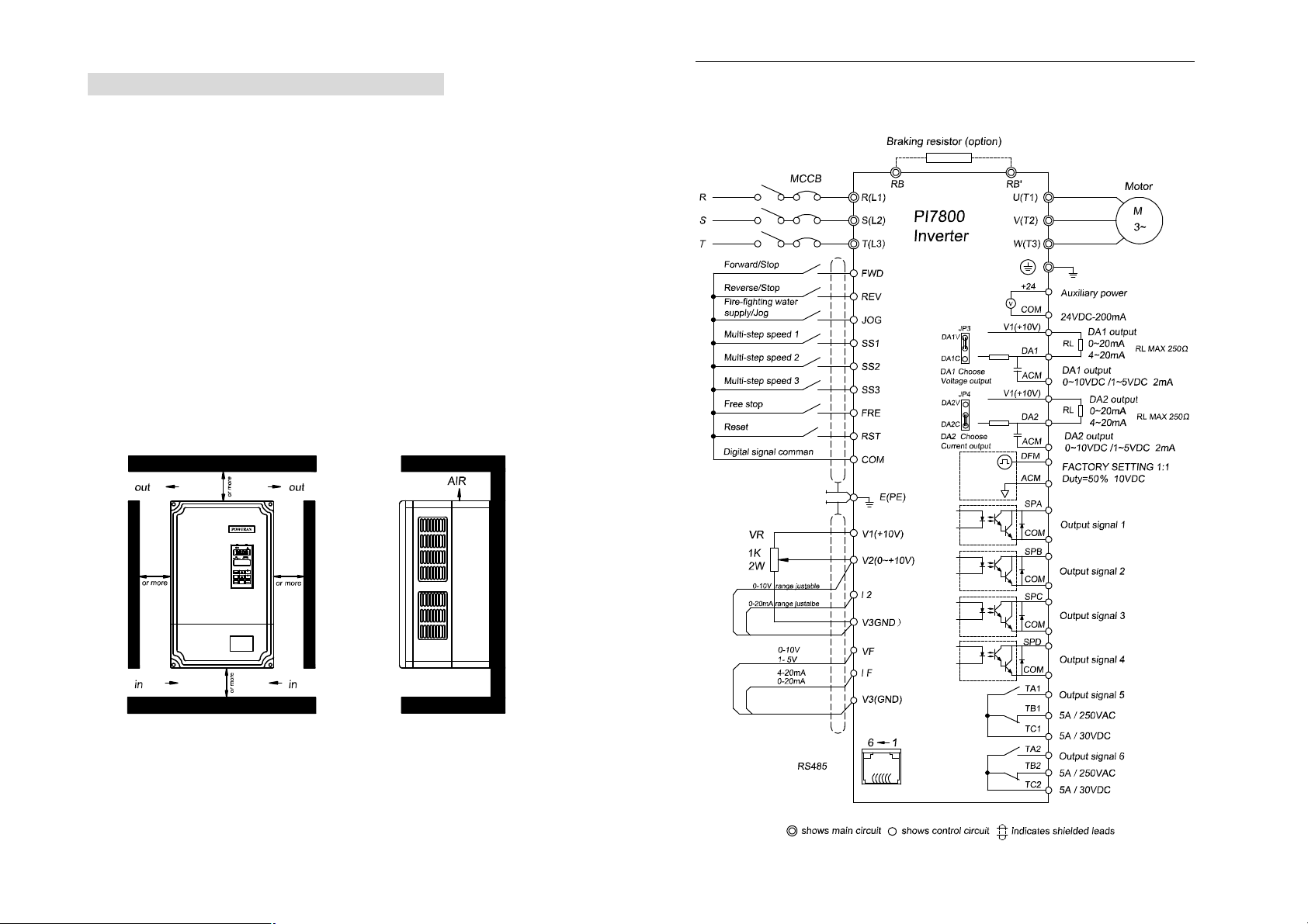
2-2. Installation
The frequency inverter must be installed by wall hooking in the indoor room with
adequate ventilation, with enough space left between it and the adjacent
objects or damper (walls) surrounding it, as shown in the below figure:
150MM
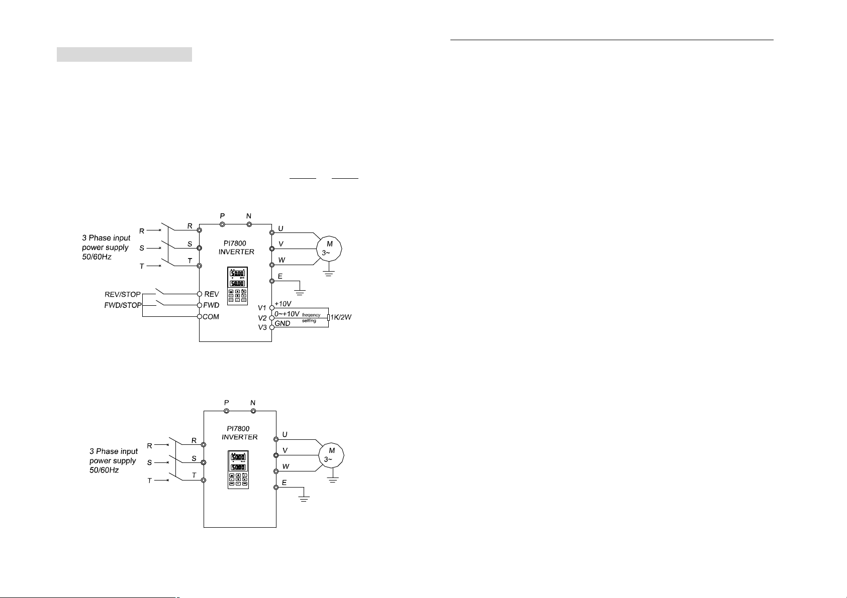
2-3-1. PI7800 Diagram
1. Wiring diagram 7.5KW~15KW and below
+ -
PRG
FWD
50MM50MM
REV
SET
STOP
ESC
JOG
RESET
DISPL
150MM
2-3. Wiring
The wiring of frequency inverter includes two parts: main circuit and control
circuit. The user must ensure correct connections according to the following
connection diagram.
3
4
SECTION II. INSTALLATION & STANDBY CIRCUIT
SECTION II. INSTALLATION & STANDBY CIRCUIT
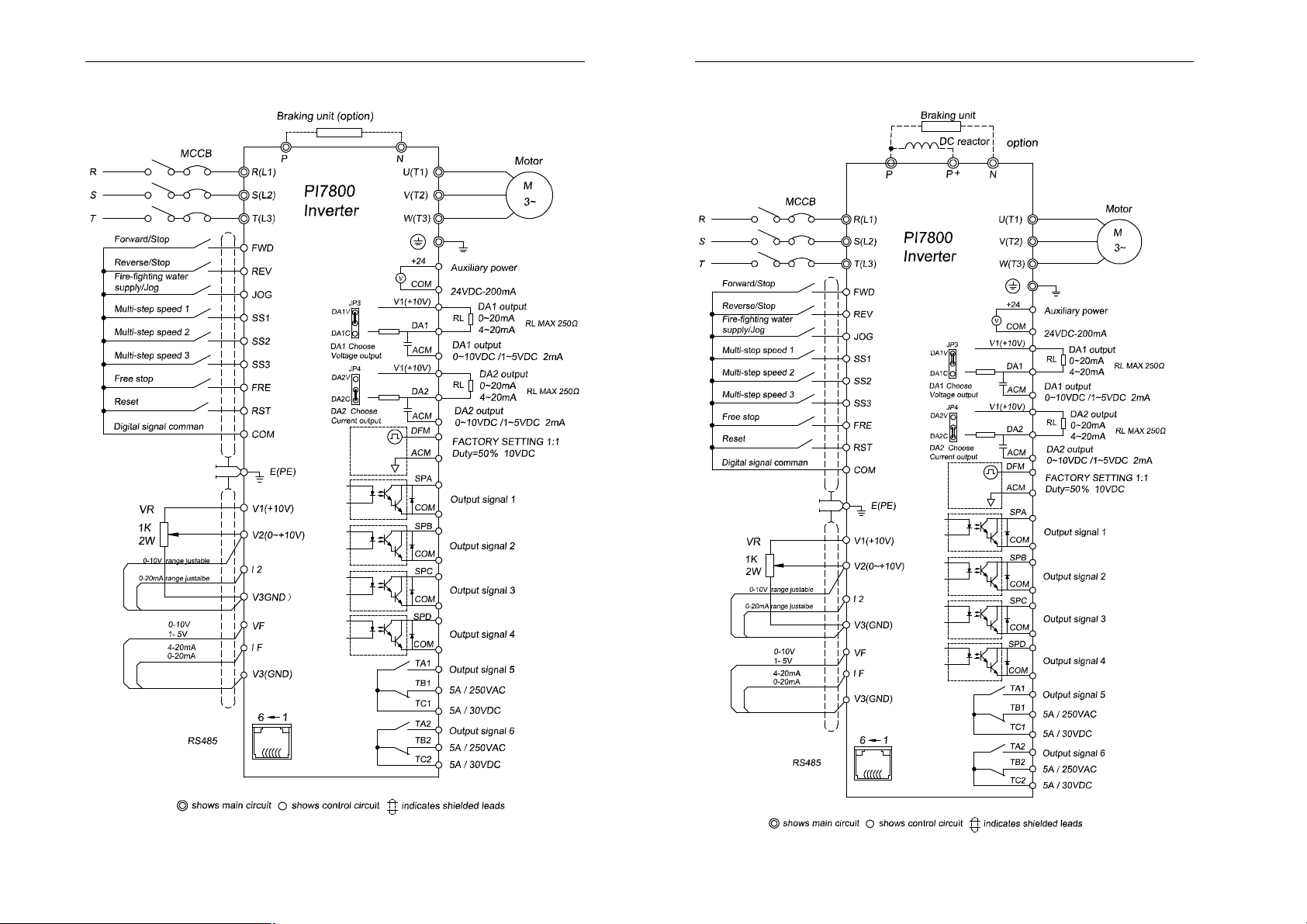
2. Wiring diagram 18.5KW~22KW
3. Wiring diagram 30~160KW
5
6
SECTION II. INSTALLATION & STANDBY CIRCUIT
SECTION II. INSTALLATION & STANDBY CIRCUIT
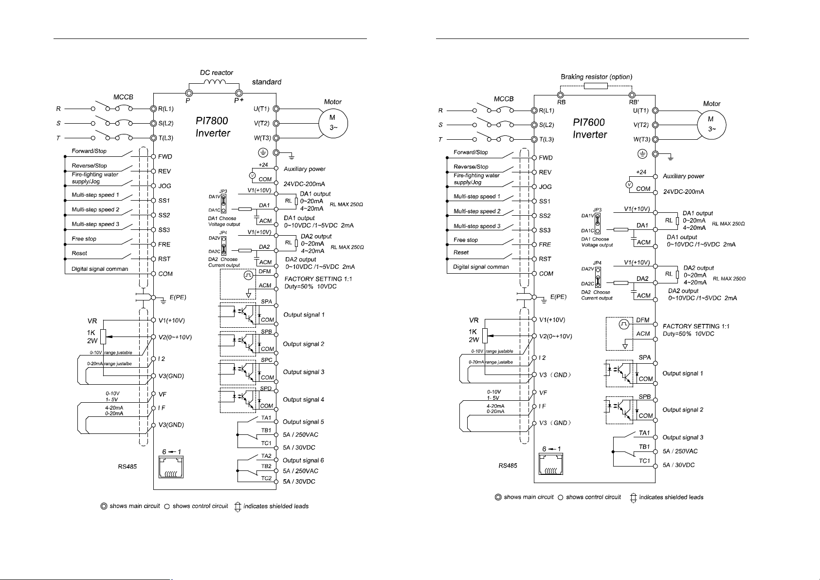
4. Wiring diagram1187~355KW
2-3-2. PI7600 Wiring diagram
1. Wiring diagram 7.5KW and below
7
8
SECTION II. INSTALLATION & STANDBY CIRCUIT
SECTION II. INSTALLATION & STANDBY CIRCUIT
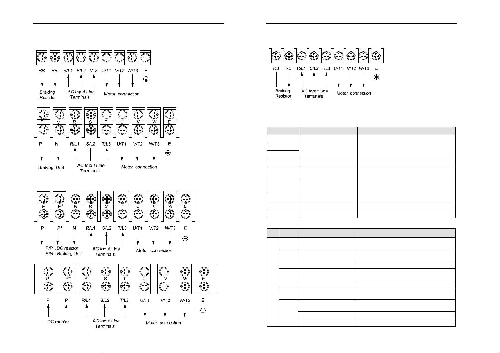
2-4. Main Circuit Terminals:
2-4-1. PI7800 Main Circuit Terminals
1. 7.5KW~15KW (380V) Main Circuit Terminal
2. 18.5~22KW (380V) Main Circuit Terminal
3. 30~160kW (380V) Main Circuit Terminal
Note: P/P+ Standard setting is short circuit; if it is with external reactance, please
disconnect and then connect it.
2-4-2. PI7600 Main Circuit Terminal
1. 7.5KW and below (380V) Main Circuit Termial
For 4N2B and 4N3B panel, “E” is on the steel panel.
Note: The above KW categaries are for G type inverter.
2-4-3. Terminal Function
Terminal Description Functions
R/L1
S/L2
T/L3
E/PE Grounding point Grounded to the earth
RB, RB′
U/T1
V/T2
W/T3
P+, N DC Bus output Connect the brake unit
P, P+ DC reactance Connect DC reactance
Power input for
frequency inverter
Connection point for
braking resistance
Connected to 3-phase power
(Single input connected to R ,T)
Connect brake resistance
3 Phase Output Connected to 3-phase motor
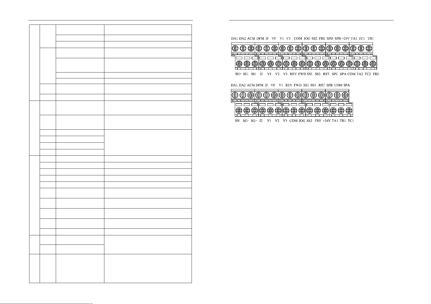
2-5. Control Circuit Terminals
Class Terminal
COM
4.187KW~355KW and above (380V) Main Circuit Terminal (132~160KW optional)
FWD Forward rotation command
REV Reverse rotation command
Control signal
JOG Jog command
SS1
9
Description Function
Common point for control
commands
Multi-step speed/acceleration
Rising/Falling control F04=4,for rising control
Frequency mode switch Switch the frequency setting mode with SS2
F05=1, Edge triggers(F62=0),and runs forward in falling
edge, stops in rising edge
F05=3, Level triggers(F62=0/1/2)
F05=1, Edge triggers (F62=0), and runs reverse in falling
edge, stops in rising edge.
F05=3, Level triggers(F62=0/1/2)
Level triggers, and executes JOG command in a lower
level, stops in a high level
F63=1/2,Short-circuited to COM to compose 7-step speed
and acceleration, level triggers, effective in a lower level
10
SECTION II. INSTALLATION & STANDBY CIRCUIT
SECTION II. INSTALLATION & STANDBY CIRCUIT
Multi-step speed/acceleration
SS2
Rising/Falling control F04=4,for falling control
Frequency mode switch Switch the frequency setting mode with SS1
Multi-step speed/acceleration
JOG control
SS3
Three-line running control F63=1/2,F62=2 Three-line terminal running for details
Program running restart For selecting the program running restart mode
FRE Free Run
RST Restore Level triggers, executes restore command in falling edge.
TA1
TB1
Output signal 5
TC1
TA2
TB2
Output signal 6
TC2
SPA/COM Output signal 1
Output signal
SPB/COM Output signal 2
SPC/COM Output signal 3
SPD/COM Output signal 4
V1,V3 Power Supply +10V, GND
V2 Voltage Input signal Range is adjustable in 0~10V
I2 Current Input signal Range is adjustable in 0~20mA
VF Voltage feedback input signal 0~10V/1~5V
IF Current feedback input signal 0~20mA/4~20mA
Common terminal of DA1 and
ACM
DA2
Power Supply of DA1 and
V1
DA2
Multi-function analog signal
DA1
Analog Input and output signal
Power
Auxiliary
Signal
Communication
output 1
Multi-function analog signal
DA2
output 2
DFM DFM multiple adjustment Factory setting 1:1, duty=50%, 10VDC
24V Power Positive terminal
COM Common point
SG+,
SG-,
SH
Communication positive/
negative signal, Screen signal
F63=1/2,Short-circuited to COM to compose 7-step speed
and acceleration, level triggers, effective in a lower level
Short-circuited to COM to compose 7-step speed and
acceleration, level triggers, effective in a lower level
F63=3 COM is short-circuited to SS3 to execute JOG
reverse command, to JOG to execute JOG forward
command, and the previous JOG direction is invalid.
Level triggers, and executes free stop command in a lower
level
TA1-TC1 is open and
TB1-TC1 is closed ( programmable)
TA2-TC2 is open and
TB2-TC2 is closed (programmable)
Output open collector signal (24VDC-50mA)
Used for common terminal when DA1/DA2 selects voltage
output
Used for Power Supply when DA1/DA2 selects current
output
0~10/1~5VDC
0~20/4~20mA
0~10/1~5VDC
0~20/4~20mA
Maximal output 24V/200mA
RS485 communication(refer to Appendix 1)
2-5-2 Control circuit terminal
1) 7KLCB.V4 Control circuit terminal
2) 7KSCB.V1 Control circuit terminal
2-6. Connection Precautions
※ Don’t install power factor capacitance or resistance-capacitance absorbing
device between the output terminals U, V, W of the frequency inverter.
※ To disassemble or replace the motor, the input power supply must be
turned off for the frequency inverter.
※ The motor or power supply can be switched on/off only after the inverter
stops its output.
※ In order to minimize the effect of electromagnetic interference, a surge
absorbing device should be installed if used electromagnetic contactor and
relay, etc. is near to the frequency inverter.
※ For external control of frequency inverter, a isolation device should be used
for the control lines or screened cable should be used.
※ A screened cable should be used as the signal connection line for input
command and must be routed separately as well, and it had better be
installed far from the main circuit.
※ When the carrier frequency is less than 3kHz, the distance between the
frequency inverter and motor must not be greater than 50 meters
(maximum). When it is above 4kHz, this distance should be reduced. The
cable for this connection had better be laid in metal conduit.
※ If the frequency inverter is equipped with peripheral devices (such as filter,
reactor), first measure its insulation resistance to the earth with 1000V
megohm meter, and ensure the resistance value is not below 4MΩ.
※ If the frequency inverter must be started frequently, don’t switch off its
power supply, and the operator must start or stop the inverter by using the
COM/FWD of the control terminal or Keyboard or RS485, in order to avoid
damage to the bridge rectifier.
11
12
SECTION II. INSTALLATION & STANDBY CIRCUIT
※ Don’t connect A.C. input power to the output terminals U, V, W of the
frequency inverter.
※ In order to prevent unexpected accidents, earthing terminal E or must
be grounded to the earth securely (the grounding resistance should be
below 100Ω). The cable size should be greater than half of belowmentioned corresponding cable size; otherwise current leakage will happen
possibly.
※ For wiring of main circuit, please refer to national rule.
※ Capacity of the motor should be equal to or smaller than that of the inverter.
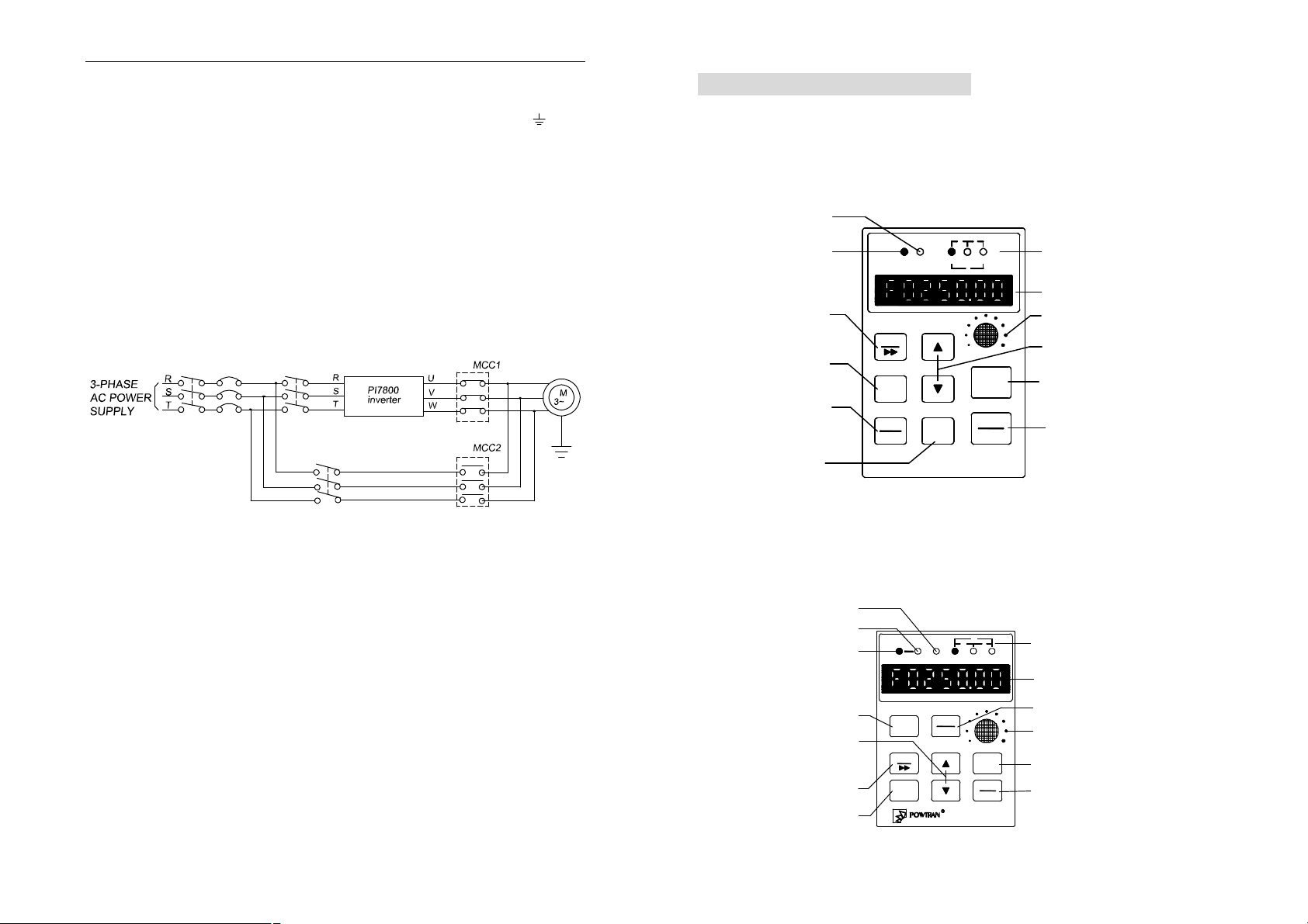
2-7. Standby circuit
When the fault or trip of the inverter may cause great loss or accident, please
add the standby circuit.
Note: confirm and test the running characteristic of the standby circuit, in order
to ensure the industrial phase and the converter phase are in the same direction.
I
nterlock relay
Section III. Operating keyboard
3-1. Operating keyboard
☆ JP3E7000 keyboard
Specification and function description
Run Indication Light
Alarm Indication Light
Paramiter
setting/shift key
RUN VAHZ
DIGITAL OPERATOR
PRG
ALARM
% S
℃
Acc. selection/
Parameter setting
SET
RUN
Escape/Display
ESC
DISPL
JOG
Jog key
The detailed function description is in the following text (JP5E7000).
*JP3E7000 Keyboard is optional for PI7800, PI76000 Family inverter.
STOP
RESET
JP-01
Data unit Prompt Light
LED main display area
Potentiometer
Parameter Alternation
Key (acc/reduction key)
Run key
Stop/Reset key
13
☆ JP5E7000 Keyboard
Specification and function description
Alarm Indication Light
Reverse command light
Forward command light
Run key
DIGITAL OPERATOR
RUN
Parameter Alternation
Key (acc/reduction key)
Paramiter
setting/shift key
PRG
SET
Acc. selection/
Parameter setting
REV
ALARMFWD VA
STOP
RESET
14
H
Z
℃
% S
JOG
ESC
DISPL
Data unit Prompt Light
LED main display area
Stop/Reset key
Potentiometer
Jog key
Escape/Display
JP-08
SECTION III. OPERATING KEYBOARD
SECTION III. OPERATING KEYBOARD
Function description
Run key:
² drive forward.
Stop/Reset key:
² Drive stops, resets after abnormity and confirms fault.
Acc. Selection /Parameter setting:
² When select parameter, press the SET key and add/reduction key,
parameter code add/reduce 10
² Restore modified value
² alternate the monitor object and monitor
Escape/display
² Escape modifying the data of function parameters
² Escape of submenu or running into menu of status display from function
menu
² Escape of fault status.
Jog key
² On: jog
² Off: stop
LED main display area
² Anterior 3 digits display the function code
² Latter 4 digits display the value as per the function code
Data unit prompt Light:
² It is formed up by 3 instruction light on the right upside of the keyboard,
different status indicates different unit of the current parameter displayed in
the LED. The units for the parameters as blow:
UNIT
Hz
%
A
S
V
none
UNIT
Hz
%
A
° C
S
V
Hz
UNIT
Hz
%
A
° C
S
V
UNIT
Hz
%
A
° C
S
V
OFFON
UNIT
Hz
%
A
° C
S
V
%VA
UNIT
Hz
%
A
° C
S
V
S
UNIT
Hz
%
A
° C
° C
S
V
° C
*JP5E7000 is the standard keyboard for PI7800, PI7600 Family inverter.
u For the 4 keypads, when the keypad is unlocked, press the and
simultaneously for 3 seconds, the keypad is locked, LED displays normally
after displaying “LoC” for 2 seconds; when the keypad is locked, press the
and simultaneously for 3 seconds, the keypad is unlocked, LED
displays normally after displaying “ULoC” for 2 seconds.
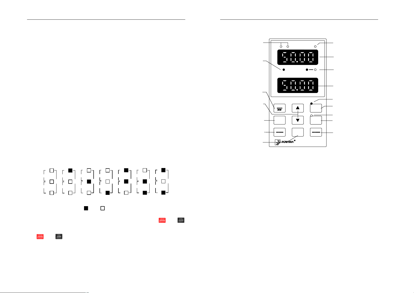
☆ JP6E7000, JP6C7000 keyboard
Specification and function description
Positive/Negative
Value indication light
Speed Status light
* Display of running status
Off:Stop status
Flash:Acc/dec status
On:Even Speed status
Paramiter
setting/shift key
Parameter Alternation
Key (acc/reduction key)
Acc. selection/
Parameter setting
Escape/Display
Jog key
+
-
SPEED-STATUS REV
DIGITAL OPERATOR
PRG
FWD
SET
ESC
DISPL
JOG
ALARM
FWD
REV
STOP
RESET
JP-07
Alarm Indication Light
LED main display area
FWS/REV Indication light
LED main display area
Forward command light
Forward key
Reverse command light
Reverse key
Stop/Reset key
function description
Forward key:
² Drive forward.
Reverse key:
² Drive reverse.
Stop/Reset key:
² Drive stops, resets after abnormity and confirms fault.
Acc. Selection /Parameter setting:
² When select parameter, press the SET key and add/reduction key,
parameter code add/reduce 10
² Restore modified value
² alternate the monitor object and monitor
Escape/display
² Escape modifying the data of function parameters
² Escape of submenu or running into menu of status display from function
menu
² Escape of fault status.
Jog key
² On: jog
² Off: stop
The upper LED main display area
² Display frequency, current, voltage, etc. Also display fuult code, password
15
16
SECTION III. OPERATING KEYBOARD
SECTION III. OPERATING KEYBOARD
right
FWD/REV Indication light
² Display motor’s running state: forward or reverse.
The nether LED main display area
² Display function code
² Display set frequency during running
JP6E7000 is standard keyboard for PI7800, PI7600 Family inverter.
JP6C7000 keyboard has the same structure and instruction with those of
JP6E7000. The difference is that the lower LED display is changed into LCD
display which displays the state and parameters in English. JP6C7000 is the
optional keyboard for PI7800, PI7600.
The second
monitor select
F65=4 output voltage
200 16.0
9 PID set Value%
The third
monitor select
F66=2 motor actual current
LCD main display area
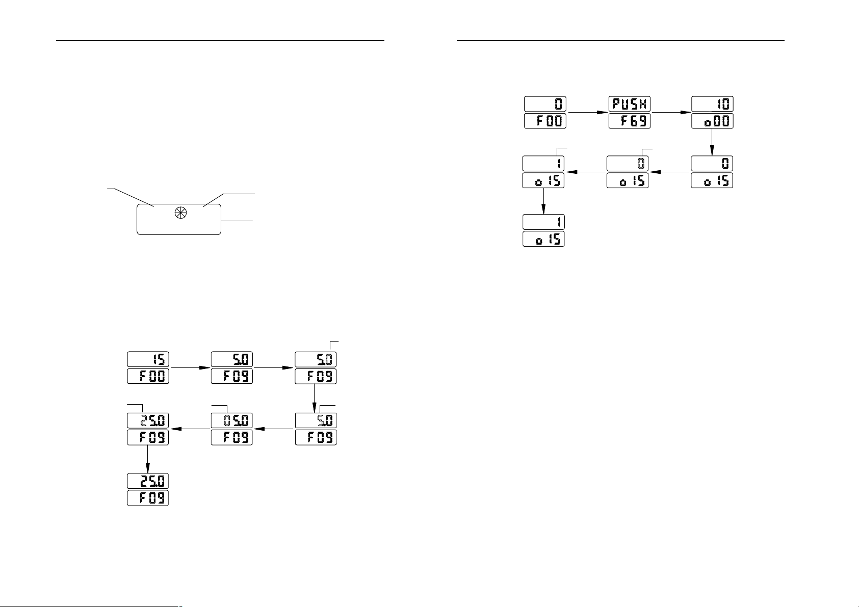
3-2. Parameters set mode
e.g. 1 Modify acceleration time F09=5.0 to F09=25.0:v
1. With F00 mode, press ▲ selecting F09, upper LED displays 5.0.
2. Press PRG for 3 times, upper LED ten digits “0” flashes.
3. Press ▲ for twice, upper LED ten digits displays “2”.
4. Press SET confirming value modification.
glitter
up LED
down LED
press
▲ key
press
PRG key
once
4. Press PRG once modifying o15.
5. Press ▲ once, upper LED flashes “1”.
6. Press SET confirming value modification.
up LED
down LED
press SET key
press
▼ key
glitter
press
▲ key
once
to affirm
press
PRG key
once
glitter
press
PRG key
once
press ▼ key
glitter
press SET key
to affirm
glitter
press
▲ key
twice
e.g. 2 Modify o15=0 to o15=1
1. With F00, press ▼ selecting F69.
2. Press PRG entering I/O group parameters menu.
3. Press ▼ selecting o15.
17
press PRG key
press
PRG key
once
once
glitter
18
SECTION IV. TEST RUNNING
Section IV. Test running
u Before connecting the power supply with the frequency converter, confirm
that the input voltage of AC power is within the rated input voltage of the
frequency converter.
u Connect the power supply with the R, S and T terminals of frequency
converter (connect with R and S terminals for single-phase input).
u Select the proper operation control method.
e.g.: analog voltage input + keyboard /terminal operating (Pr.F04=1, Pr.F05=1).
The frequency command is controlled by terminal V2, and the operation is
controlled by the keyboard and terminal FWD、REV.
ALARM
FWD
REVSPEED-STATUS
DIGITAL OPERATOR
PRG
STOP
ESC
RESET
DISPL
JP-07
※ Check JOG control.
※ Confirm the acceleration and deceleration time.
※ Connect with the motor.
※ Run the motor at low speed and check its rotation direction.
Check if all the displays and outputs during the operation are correct.
e.g.: keyboard adjust speed + keyboard operating (Pr.F04=0, Pr.F05=0)
The frequency command is controlled by the key , and operation is controlled by
the key FWD、REV controlling the forward and reverse.
ALARM
FWD
REVSPEED-STATUS
DIGITAL OPERATOR
PRG
STOP
ESC
RESET
DISPL
JP-07
※ Running the unit without load, regulate the speed and check.
※ Confirm the min. and max values of the set output frequency.
19
20
optimized space vector
SECTION V. FUNCTION PARAMETER TABLE
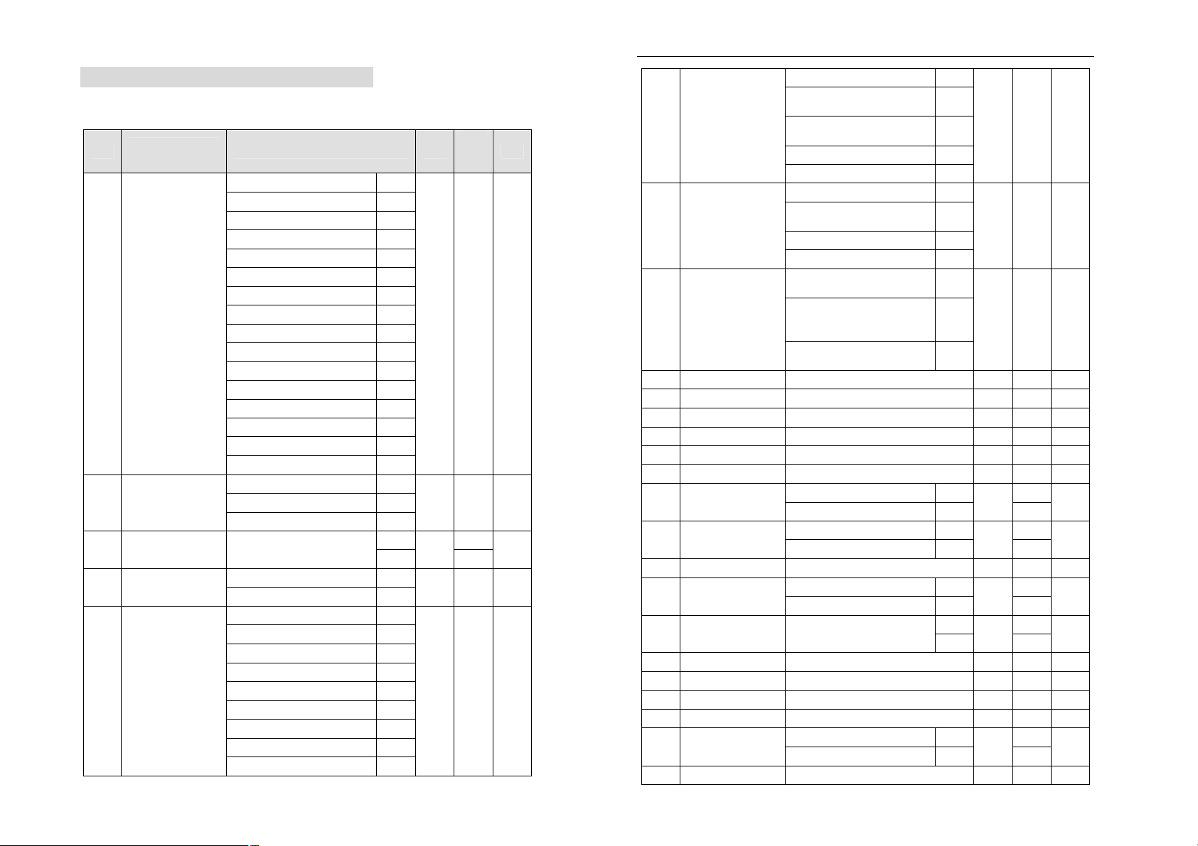
Section V. Function parameter table
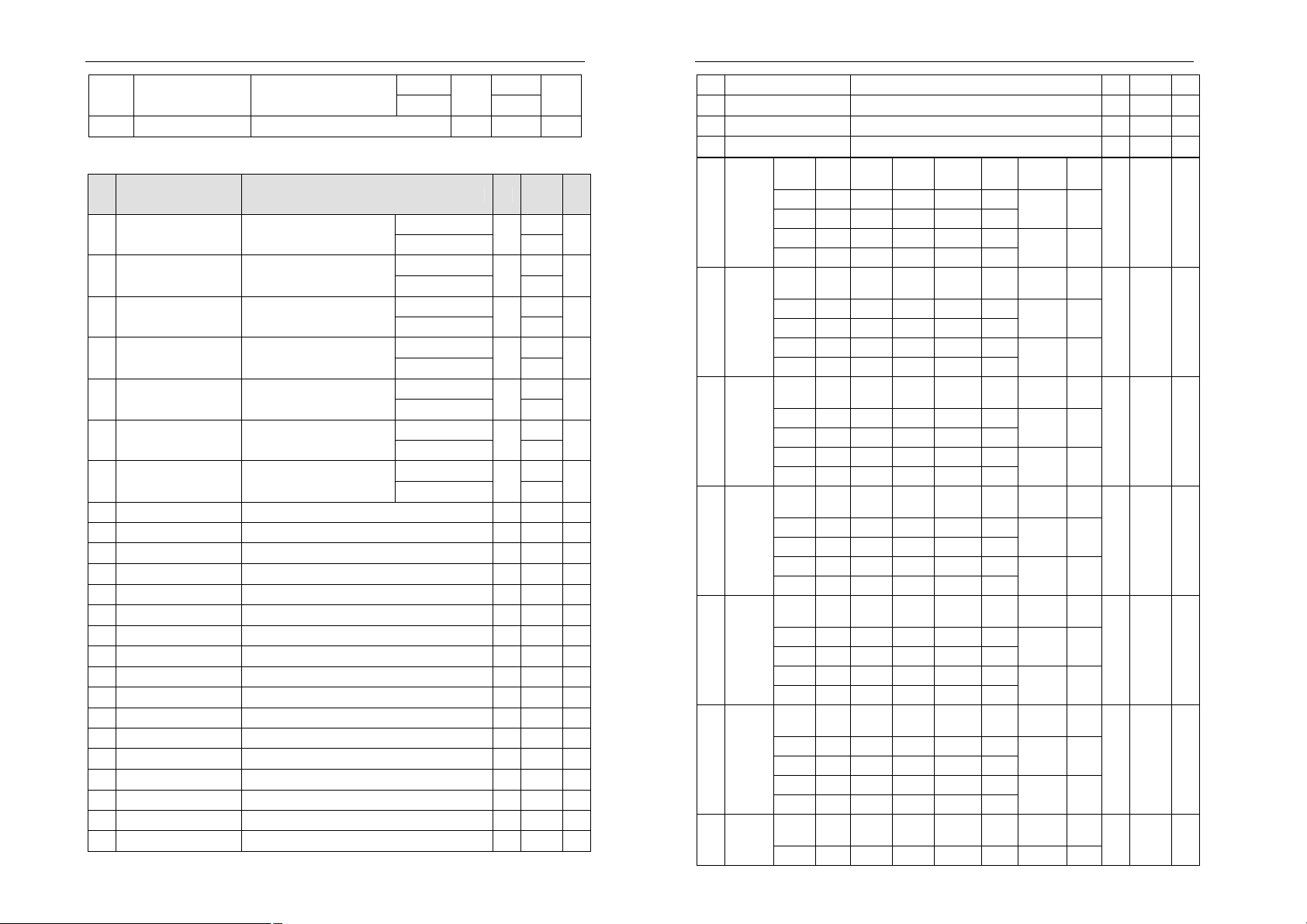
5-1. Basic Parameters
Ref
F00
F02
F03 fre. multiple set
F04
LCD keyboard
explanation
monitor select
set frequency
fre. set mode
Range of set value Unit
Set frequency 0
Actual frequency 1
Motor actual current 2
Actual current percent 3
DC Bus voltage 4
Actual output voltage 5
Actual motor speed 6
Total running time 7
IGBT temperature 8
PID set value 9
PID feedback value 10
Motor output power 11
Excitation heft set value 12
Excitation heft actual value 13
Torque heft set value 14
Torque heft actual value 15
No PG V/F control 0
PG V/F control 1 F01 control methods
PG vector control 2
Lower frequency~Upper
frequency
×1 0
×10 1
Keypad 0
V2 1
I2 2
V2+I2 3
Ascend/Descend control 1 4
Program running 5
Traverse running 6
PID control 7
Keypad potentionmeter set 8
F03=0
F03=1
Factor
y
setting
- 0 Y
- 0 N
50.00
Hz
500.0
- 0 N
- 0 N
Y/N
Y
V2 Forward/Reverse set 9
Keypad potentionmeter
FWD/REV set
V2 proportional linkage
adjustment
10
11
I2 proportional linkage 12
Ascend/Descend control 2 13
Keypad+RS485/CAN 0
F05 run control mode
Keypad +
terminal+RS485/CAN
1
- 0 Y
RS485/CAN 2
terminal 3
Asynchronous space vector
PWM
0
Stepless & subsection
F06 waveform mode
synchronous space vector
1
- 1 N
PWM
2 phase
PWM
F07 auto.torque boost
0~10 % 0 Y
F08 V/F boost mode 0~61
F09 accelerate time 0.1~3200.0
F10 decelerate time 0.1~3200.0
2
-
2 N
s
10.0 Y
s
10.0 Y
F11 slip compensate 0~10 % 0 N
F12 O.P. voltage ratio
F13 max. frequency
F14 basic frequency
50~110 % 100 N
10.00~300.00 F03=0
100.0~800.0 F03=1
5.00~ F13 F03=0
50.0~ F13 F03=1
Hz
Hz
50.00
500.0
50.00
500.0
F15 carrier frequency 1.0~16.0 kHz ★ Y
F16 Lower frequency
0.00~ F17 F03=0
0.0~ F17 F03=1
F17 upper frequency F16~F13
F18 S curve acc. start
0.0~50.0 % 0.0 Y
F03=0
F03=1
Hz
Hz
0.00
0.0
50.00
500.0
F19 S curve acc. stop 0.0~50.0 % 0.0 Y
F20 S curve dec. start
F21 S curve dec. stop
F22 min. running fre.
0.0~50.0 % 0.0 Y
0.0~50.0 % 0.0 Y
0.00~ F13 F03=0
0.0~ F13 F03=1
Hz
0.00
0.0
F23 DC brake current 0~135 % 100 Y
N
N
N
N
N
21
22
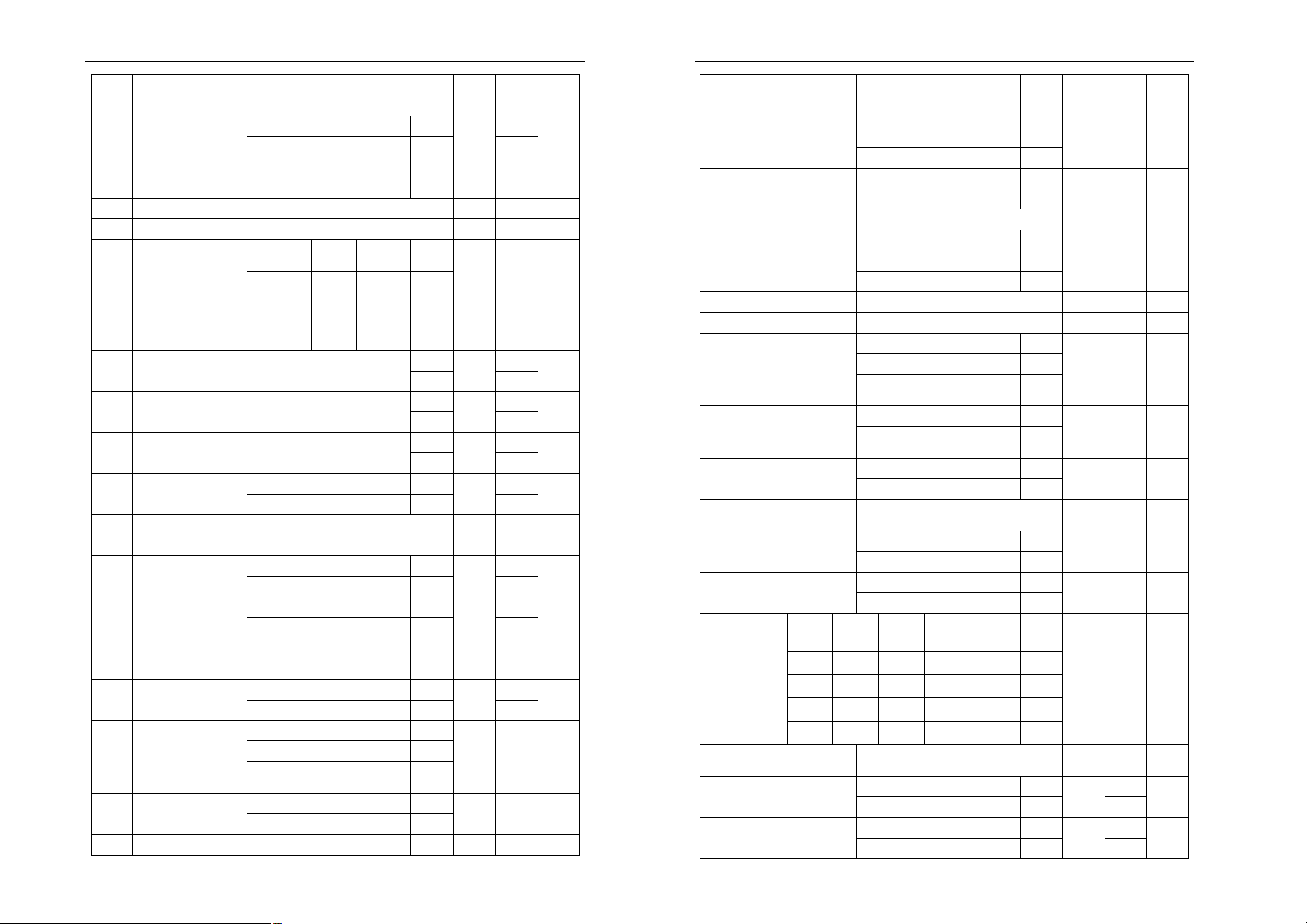
SECTION V. FUNCTION PARAMETER TABLE
N
SECTION V. FUNCTION PARAMETER TABLE
F24 start brake time 0.0~60.0 s 0.0 N
F25 stop brake time 0.0~60.0 s 0.0 N
F26 brake start fre.
F27 stopping mode
F28
F29
jog acc. time 0.1~3200.0 s 1.0 N
jog dec. time 0.1~3200.0 s 1.0 N
F30 Jog function set
JOG stop
Reset to
the state
before JOG
0.00~F13 F03=0
0.0~F13 F03=1
Deceleration stop 0
Free stop 1
Ten’s
mode
Stop
running
place
0 Forward 0
1 Reverse 1
F31 jog frequency set F16~F17
F32
F33
F34 traverse differ.
traverse fre. 1 F33~F17
traverse fre. 2 F16~F32
0.00~5.00 F03=0
0.0~50.0 F03=1
direction digit
F03=0
F03=1
F03=0
F03=1
F03=0
F03=1
0.00
Hz
0.0
- 0 N
- 0 N
6.00
Hz
60.0
40.00
Hz
400.0
20.00
Hz
200.0
2.00
Hz
20.0
F35 traverse time 1 0.0~3200.0 s 2.0 Y
F36 traverse time 2 0.0~3200.0 s 2.0 Y
F37 skip frequency 1
F38 skip frequency 2
F39 skip frequency 3
F40 skip frequency range
0.00~F13 F03=0
0.0~F13 F03=1
0.00~F13 F03=0
0.0~F13 F03=1
0.00~F13 F03=0
0.0~F13 F03=1
0.00~5.00 F03=0
0.0~50.0 F03=1
Hz
Hz
Hz
Hz
0.00
0.0
0.00
0.0
0.00
0.0
0.00
0.0
Invalid 0
F41
auto. Voltage
regulation
F42 OU stall protect
F43
current limit
Valid 1
Valid but useless when
decelerating
Invalid 0
Valid 1
Invalid 0
- 0 Y
2
- 1 Y
- 0 Y
Valid 1
Invalid 0
Y
Pick up mode when power
down
1 F44 rate track select
- 0 N
Pick up mode when start 2
F45 elec. o.h. protect
F46
protect level 120~250 % ★ N
Invalid 0
Valid 1
- 1 Y
Invalid 0
F47 consumed brake
Safe mode 1
- 0 Y
General mode 2
F48 Fault reset times 0~10 - 0 N
F49 Fault reset time 0.5~20.0 s 1.0 N
Single circulation 0
Program running
Y
F50
mode
Y
F51
Restart mode
Y
F52 RST input signal
Y
F53
Fan start temp.
(options)
F54 Motor run direction
Y
F55
Motor reverse
forbidden
Y
dec. time
Y
Y
Time
unit
F56
setting
% in energy saving
F57
F58
F59
×1s 0 ×1s 0
×30s 1 ×30s 1
×600s 2 ×600s 2
×3600s 3 ×3600s 3
energy
FDT fre. set 1
FDT fre. set 2
Continuous circulation 1
Single circulation command
running
Runs at step 1 0
Runs at the step before
stopping
Reset 0
External fault/Reset 1
0.0~60.0 ℃ 0.0 Y
FWD command,motor forwards 0
FWD command,motor reverses 1
Reverse allowable 0
Reverse forbidden 1
hundred'
s place
Acc. time
tens
place
reserved digit
30~100 % 100 N
F59~ F13 F03=0
F59~ F13 F03=1
0.00~ F58 F03=0
0.0~ F58 F03=1
2
1
- 0 N
- 0 N
- 0 Y
- 0 N
- 0 N
- 0
0.00
Hz
0.0
0.00
Hz
0.0
Y
Y
23
24

SECTION V. FUNCTION PARAMETER TABLE
Hz
Hz
Hz
Hz
Hz
Hz
SECTION V. FUNCTION PARAMETER TABLE
F60
F61
F62
F63
F64
F65
F66
Fre. Inspection
range
Load type
Terminal control
modes
MSS terminal
function selection
Polarity of input
terminal
Monitor Subject
Reserved
0.00~5.00 F03=0
0.0~50.0 F03=1
General 0
Water Pump 1
Blower fan 2
Plastic jetting mould machine 3
Braiding machine 4
Hoister 5
Pumping jack 6
Belt conveyor 7
Electromagnetic stirring power
supply
Standard running control 0
2-point running control 1
3-point running control 2
Invalid 0
MSS multi-step speed control 1
MSS multi-step acceleration
control
JOG forward/ reverse control 3
Frequency setting mode switch 4
Upper torque shifted 5
MSS time running 6
Control mode shifted 7
Reset program running
segment
0~255 - 0 N
Set frequency 0
Actual frequency 1
Motor actual current 2
Actual current percent 3
DC Bus voltage 4
Actual output voltage 5
Actual motor speed 6
Total running time 7
IGBT temperature 8
PID set value 9
PID feedback value 10
Motor output power 11
8
2
8
0.00
Hz
0.0
0 N
- 0 N
- 0 N
-
1
-
2
Y
Excitation heft set value 12
Excitation heft actual value 13
Torque heft set value 14
Torque heft actual value 15
F67
V/F curve set
F68 MSS speed control
F69 I/O group select
F70 CUR group select
F71 SPD group select
Useless
Press
[PROG/ENT]
- Y
F72 PID group select
F73 SYS group select
F74 MOT group select
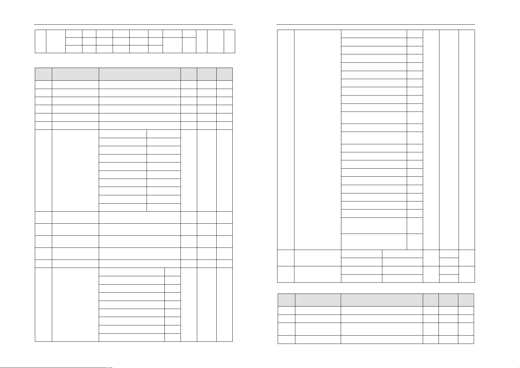
5-2. Other Parameters
5-2-1. F67 V/F curve [V/F]
Ref
U00
LCD keyboard
explanation
V/F set fre 1
Range of set value Unit
0.00~U02 F03=0
0.0~U02 F03=1
U01 V/F set voltage 1 0~U03 % 5 N
U02
V/F set fre. 2 U00~U04
F03=0
F03=1
U03 V/F set voltage 2 U01~U05 % 10 N
U04
V/F set fre. 3 U02~U06
F03=0
F03=1
U05 V/F set voltage 3 U03~U07 % 15 N
N
U06
V/F set fre. 4 U04~U08
N
F03=0
F03=1
U07 V/F set voltage 4 U05~U09 % 20 N
U08
V/F set fre. 5 U06~U10
F03=0
F03=1
U09 V/F set voltage 5 U07~ U11 % 25 N
U10
V/F set fre. 6 U08~U12
F03=0
F03=1
U11 V/F set voltage 6 U09~U13 % 30 N
U12
V/F set fre. 7 U10~U14
F03=0
F03=1
U13 V/F set voltage 7 U11~U15 % 35 N
Hz
Factory
setting
5.00
50.0
10.00
100.0
15.00
150.0
20.00
200.0
25.00
250.0
30.00
300.0
35.00
350.0
Y/N
N
N
N
N
N
N
N
25
26
SECTION V. FUNCTION PARAMETER TABLE
Factory
Y
Y
Y
Y
Y
Y
Y
step
step
step
step
step
step
step
SECTION V. FUNCTION PARAMETER TABLE
U14
V/F set fre. 8 U12~F13
F03=0
F03=1
Hz
40.00
400.0
U15 V/F set voltage 8 U13~100 % 40 N
5-2-2. F68 MSS group [MSS]
Ref
H00
H01
H02
H03
H04
H05
H06
H07
H08
H09
H10
H11
H12
H13
H14
H15
H16
H17
H18
H19
H20
H21
H22
H23
LCD keyboard
explanation
1 step speed 1X F16~F17
2 step speed 2X F16~F17
3 step speed 3X F16~F17
4 step speed 4X F16~F17
5 step speed 5X F16~F17
6 step speed 6X F16~F17
7 step speed 7X F16~F17
Range of set value Unit
F03=0 5.00
F03=1
F03=0 30.00
F03=1
F03=0 20.00
F03=1
F03=0 30.00
F03=1
F03=0 40.00
F03=1
F03=0 45.00
F03=1
F03=0 50.00
F03=1
Hz
Hz
Hz
Hz
Hz
Hz
Hz
setting
300.0
200.0
300.0
400.0
450.0
500.0
1 step time T1 0.0~3200.0 s 2.0 Y
2 step time T2 0.0~3200.0 s 2.0 Y
3 step time T3 0.0~3200.0 s 2.0 Y
4 step time T4 0.0~3200.0 s 2.0 Y
5 step time T5 0.0~3200.0 s 2.0 Y
6 step time T6 0.0~3200.0 s 2.0 Y
7 step time T7 0.0~3200.0 s 2.0 Y
acc. time at1 0.1~3200.0 s 10.0 Y
dec. time dt1 0.1~3200.0 s 10.0 Y
acc. time at2 0.1~3200.0 s 10.0 Y
dec. time dt2 0.1~3200.0 s 10.0 Y
acc. time at3 0.1~3200.0 s 10.0 Y
dec. time dt3 0.1~3200.0 s 10.0 Y
acc. time at4 0.1~3200.0 s 10.0 Y
dec. time dt4 0.1~3200.0 s 10.0 Y
acc. time at5 0.1~3200.0 s 10.0 Y
dec. time dt5 0.1~3200.0 s 10.0 Y
27
50.0
N
H24
H25
H26
H27
Y/N
H28
H29
H30
H31
H32
H33
H34
acc. time at6 0.1~3200.0 s 10.0 Y
dec. time dt6 0.1~3200.0 s 10.0 Y
acc. time at7 0.1~3200.0 s 10.0 Y
dec. time dt7 0.1~3200.0 s 10.0 Y
Multi-
speed 1
running
direction
Multi-
speed 1
running
direction
Multi-
speed 1
running
direction
Multi-
speed 1
running
direction
Multi-
speed 1
running
direction
Multi-
speed 1
running
direction
Multi-
speed 1
dec.
time
×1s 0 ×1s 0 ×1s 0
×30s 1 ×30s 1 ×10s 1
×600s 2 ×600s 2 ×100s 2
×3600s 3 ×3600s 3 ×1000s 3
dec.
time
×1s 0 ×1s 0 ×1s 0
×30s 1 ×30s 1 ×10s 1
×600s 2 ×600s 2 ×100s 2
×3600s 3 ×3600s 3 ×1000s 3
dec.
time
×1s 0 ×1s 0 ×1s 0
×30s 1 ×30s 1 ×10s 1
×600s 2 ×600s 2 ×100s 2
×3600s 3 ×3600s 3 ×1000s 3
dec.
time
×1s 0 ×1s 0 ×1s 0
×30s 1 ×30s 1 ×10s 1
×600s 2 ×600s 2 ×100s 2
×3600s 3 ×3600s 3 ×1000s 3
dec.
time
×1s 0 ×1s 0 ×1s 0
×30s 1 ×30s 1 ×10s 1
×600s 2 ×600s 2 ×100s 2
×3600s 3 ×3600s 3 ×1000s 3
dec.
time
×1s 0 ×1s 0 ×1s 0
×30s 1 ×30s 1 ×10s 1
×600s 2 ×600s 2 ×100s 2
×3600s 3 ×3600s 3 ×1000s 3
dec.
time
×1s 0 ×1s 0 ×1s 0 forward 0
kilobit
kilobit
kilobit
kilobit
kilobit
kilobit
kilobit
Acc.
time
Acc.
time
Acc.
time
Acc.
time
Acc.
time
Acc.
time
Acc.
time
hundred'
s place
hundred'
s place
hundred'
s place
hundred'
s place
hundred'
s place
hundred'
s place
hundred'
s place
Running
time
Running
time
Running
time
Running
time
Running
time
Running
time
Running
time
tens
place
tens
place
tens
place
tens
place
tens
place
tens
place
tens
place
Running
direction
forward 0
reverse 1
Running
direction
forward 0
reverse 1
Running
direction
forward 0
reverse 1
Running
direction
forward 0
reverse 1
Running
direction
forward 0
reverse 1
Running
direction
forward 0
reverse 1
Running
direction
digit
digit
digit
digit
digit
digit
digit
- 0 Y
- 0 Y
- 0 Y
- 0 Y
- 0 Y
- 0 Y
- 0 Y
28
SECTION V. FUNCTION PARAMETER TABLE
SECTION V. FUNCTION PARAMETER TABLE
running
direction
×30s 1 ×30s 1 ×10s 1
×600s 2 ×600s 2 ×100s 2
×3600s 3 ×3600s 3 ×1000s 3
reverse 1
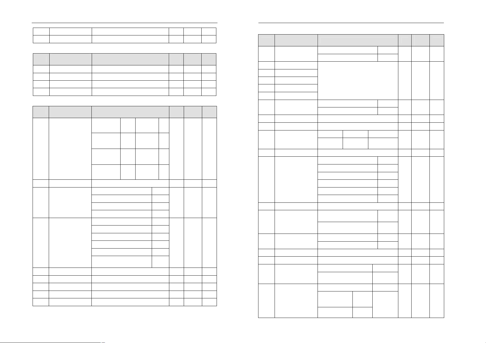
5-2-3. F69 I/O group [I/O]
Ref
LCD keyboard
explanation
Range of set value Unit
o00 V2 input filter time 2~200 ms
o01 V2 min. input voltage
o02 V2 max. input voltage
0.00~o02 V 0.00 Y
o01~10.00 V 10.00 Y
Factory
setting
10 Y
o03 I input filter time 2~200 ms 10 Y
o04 I input min. current
o05 I input max. current
0.00~o05 mA 0.00 Y
o04~20.00 mA 20.00 Y
No Function 0
Set frequency 1
Actual frequency 2
Actual current 3
o06
o07
DA1 Ouput
DA2 Output
Output voltage 4
Bus voltage 5
-
0
-
0
IGBT temperature 6
Output power 7
Output speed 8
Actual torque 9
DA1 output lower
o08
o09
o10
o11
o12
o13
o14
o15
o16
o17
o18
adjustment
DA1 output upper
adjustment
DA2 output lower
adjustment
DA2 output upper
adjustment
DFM multiple 1~20 - 1 Y
O.P. signal sel. 1
O.P. signal sel. 2
O.P. signal sel. 3
O.P. signal sel. 4
O.P. signal sel. 5
O.P. signal sel. 6
Over current inspection 2
Over load inspection 3
Over voltage inspection 4
0~o09 % 0.0 Y
o08~100.0 % 100.0 Y
0~ o11 % 0.0 Y
o10~100.0 % 100.0 Y
No function 0
Fault alarm 1
-
-
-
-
-
-
0
0
0
0
1
8
Lack voltage inspection 5
Low load inspection 6
Over heat inspection 7
Running state with command 8
Y/N
Y
Y
Y
Y
Y
Y
Y
Y
PID feedback signal abnormity
9
Motor reverse 10
Set frequency arrival 11
Upper limit frequency 12
Lower limit frequency 13
FDT frequency 1 arrival 14
FDT frequency level inspection 15
0 speed running 16
Position arrival 17
PG fault 18
Program running 1 cycle
finished
Speed pursue mode inspection
Running state without
command
19
20
21
Inverter reverse command 22
Deceleration running 23
Acceleration running 24
High pressure arrival 25
Low pressure arrival 26
Inverter’s rated current arrival
27
Motor’s rated current arrival 28
Set fre. arrives lower fre. 29
FDT frequency set 2 arrives 30
o19
o20
Minimum input
frequency
Maximum input
frequency
Fault code output
(o13~o16 valid)
Digits of frequency
output (o13~o16 valid)
0.00~F13 F03=0 0.00
0.0~F13 F03=1
0.00~F13 F03=0 50.00
0.0~F13 F03=1
31
32
-
0.0
-
500.0
5-2-4. F70 CUR group [CUR]
Ref
LCD keyboard
explanation
Range of set value Unit
Factory
setting
C00 detect filter time 2~200 ms 10 Y
C01
C02
C03
re. filter time 2~200 ms 10 Y
integral time of
current loop
0~9999 ms 500 Y
proportion gain 0~1000 % 100 Y
Y
Y
Y/N
29
30
SECTION V. FUNCTION PARAMETER TABLE
Adjustment
password or Input
SECTION V. FUNCTION PARAMETER TABLE
C04
torque setting 0.0~100.0 % 80.0 Y
C05 excitation setting 0.0~100.0 % 60.0 Y
5-2-5. F71 SPD group [SPD]
Ref
d00
d01
LCD keyboard
explanation
Range of set value Unit
filter time 2~200 ms 10 Y
integral time 0.01~100.00 s 0.25 Y
Factory
setting
d02 differential time 0.000~1.000 s 0.000 Y
d03
proportion gain 0~1000 % 100 Y
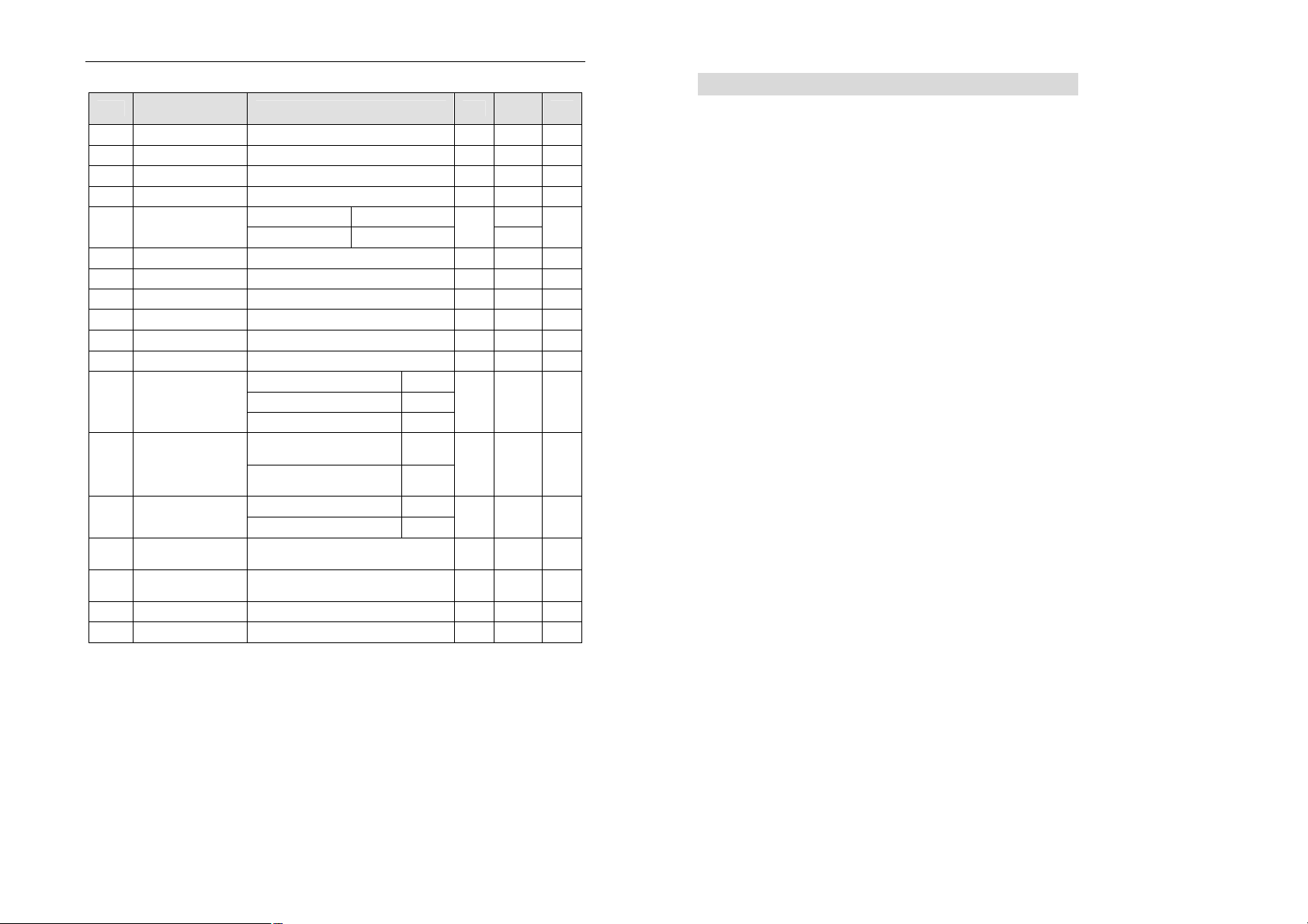
5-2-6.F72 PID group [PID]
Ref
LCD keyboard
explanation
P00 PID regulate mode
P01
O.P. fre. limit 0~110 % 100 N
Range of set value Unit
Abnormity
management
Warning
Continuous
running
Warning
Decelerating
running
Warning Free
stop
Tens
digit
1
2
mode
Negative
action
Positive
action
3
Unit
0
1
Factory
setting
- 10 N
External terminal IF:0~20mA 0
P02
Feedback signal
select
External terminal IF:4~20mA 1
External terminal VF:0~10V 2
- 2 N
External terminal VF:1~5V 3
External terminal I2:0~20mA 0
External terminal I2:4~20mA 1
External terminal V2:0~10V 2
P03 set signal select
Keyboard input 3
- 3 N
RS485 input 4
P04
P05
Setting by keypad
potentionmeter
key set signal 0.0~100.0 % 50.0 Y
integral time 0.01~100.00 s 0.25 Y
5
P06 differential time 0.000~1.000 s 0.000 Y
P07 proportion gain 0~1000 % 100 Y
P08 fault detect time 0.0~3200.0 s 300.0 Y
Y/N
Y/N
5-2-7. SYS group [SYS]
Ref
y00
y01
y02
y03
y04
y05
LCD keyboard
explanation
Restore factory
setting
fault record 1
fault record 2
fault record 3
fault record 4
fault record 5
y06 Fault record reset
y07 rated O.P. current
Range of set value Unit
No reset 0
Instant reset 1
Press [PRG] and [▲], the frequency,
current and running state of fault time can
be known.
No activity 0
Reset 1
0.1~1000.0 A ★ N
Factory
setting
- 0 N
- - N
- 0 Y
y08 rated I.P. voltage 100~1140 V ★ N
70 0 3
y09
product series
Family serial
Function
code
Input voltage
level
- ★ N
y10 software version - - - N
Baud rate 1200 0
Baud rate 2400 1
y11 baud rate
Baud rate 4800 2
Baud rate 9600 3
- 3 N
Baud rate 19200 4
Baud rate 38400 5
y12 communi. address
y13
y14
total time set
total time unit
y15 Manufacture date
y16 making month/day
Clear automatically after
Continuous accumulation after
1~128 - 8 N
starting
starting
Hour 0
Day 1
0
- 1 Y
1
- 0 Y
YYYY - - N
MMDD - - N
0~9999 set range
y17
decode input
Record of times of wrong
decode
display
content
- - Y
0~9999 set range
No setting
y18 password input
decode correct
Parameters
locked
deco
code
display
content
- - Y
Y/N
31
32
SECTION V. FUNCTION PARAMETER TABLE
5-2-8. MOT group [MOT]
Ref
b00
b01 motor rated cur. y07×(30%~120%) A ★ N
b02 motor rated vol. 100~1140 V ★ N
b03 motor rated speed
b04
b05 Motor un-load cur.
b06
b07
b08
b09 mutual inductance
b10
b12 PG rotate direct.
b13
b14
b15
b16
b17
NOTE:
1) Y/N means the parameter is adjustable or not during running, Y means it is
2) ★ means the parameter’s factory setting is affected by the power and type.
LCD keyboard
explanation
motor poles 1~8 - 2 N
motor rated
frequency
stator resistor 0.000~30.000 ohm 0.000 N
rotor resistor 0.000~30.000 ohm 0.000 N
leakage inductance 0.0~3200.0 mH
PG pulse 300~9999 - 2048 N
PG cut action
Motor parameter
measure
Rotate speed display
plus
Percentage linkage
modulus
reserved 0 - 0 N
reserved 0 - 0 N
adjustable, N means it is not.
Alarm & decelerate to stop 1 b11
Phase A is foregoing when
Phase B is foregoing when
Range of set value Unit
500~5000 rpm 1500 N
0.00~F13 F03=0 50.00
0.0~F13 F03=0
0~b01 A ★ N
0.0~3200.0 mH 0.0 N
Continue running 0
Alarm and stop freely 2
motor forwards
motor forwards
No measurement 0
Measured before running
0.1~2000.0 % 100.0 Y
0.10~10.00 - 1.00 Y
33
0
1
1
Factory
setting
%
500.0
0.0 N
- 0 N
- 0 N
- 0 N
Y/N
N
Section VI. Function Parameter Description
6-1. Basic parameter:
F00: Monitor selection factory setting: 0
The value range is 0~15 monitoring 0~15 different objects under running.
Monitor objects under running
0: Set frequency
Set frequency under frequency setting mode.
1: Actual frequency
Current output frequency.
2: Motor actual current
Detected value of motor’s current.
3: Actual current percentage
Percentage of motor’s actual current and rated current.
4: DC bus voltage
Detected voltage of DC bus.
5: Output voltage
Actual output voltage of inverter.
6: Actual motor speed rpm
During running, the display of the adjusted motor’s actual rotate speed=60 ×
Actual output frequency × Rotate speed display plus/Motor poles
e.g. Actual output frequency50.00Hz, Rotate speed display plus b14=100.0%,
Motor poles b00=2, the display of the adjusted motor’s actual rotate
speed=1500rpm.
During stopping state, checking the motor speed according to residual stress,
renewed speed 500ms.
The display of the adjusted motor’s actual rotate speed=60 × residual stress
frequency × rotate speed display plus/Motor poles
7: Total running time
This parameter indicates the total running time, and the unit is hour or day.
e.g. If led display value is 10.31, y14 is 0, the actual running time of the
machine is 10 hours,18 minutes and 36 seconds; if led display value is 20.03
and y14 is 1, the actual running time of the machine is 20 days,43 minutes and
12 seconds.
8: IGBT temperature
Detected IGBT temperature inside inverter.
9: PID set value
Set value percentage when running under PID adjustment.
10: PID feedback value
11: Motor output power
Motor actual output power percentage.
12: Excitation heft set value
Motor’s set excitation heft percentage.
13: Excitation heft actual value
Motor’s actual excitation heft percentage.
14: Torque heft set value
Motor set torque percentage.
34
SECTION VI. FUNCTION PARAMETER DESCRIPTION
SECTION VI. FUNCTION PARAMETER DESCRIPTION
15: Torque heft actual value
Motor actual torque hefts percentage.
F01: Control mode factory setting: 0
This parameter value range is 0~2.
0: Without PG V/F control. V/F space voltage vector control.
1: With PG V/F control. V/F space voltage vector control + speed sensor.
2: With PG vector control .vector control + speed sensor
F02: Set frequency factory setting: 50.00/500.0Hz
Setting running frequency can be from lower frequency to upper frequency.
F03: Frequency multiple setting factory setting: 0
0: Set frequency display accuracy is 0.01Hz. With this accuracy, F13 maximum
frequency range is 10.00~300.00Hz.
1: Set frequency display accuracy is 0.1Hz. With this accuracy, F13 maximum
frequency range is 100.0~800.0Hz.
F04: Frequency setting mode factory setting: 0
Frequency setting modes can be set by the value 0~10, as following:
0: Keypad or RS485 set
1: Set frequency by analog input V2
2: Set frequency by analog input I2
3: By analog input V2 and I2 simultaneity
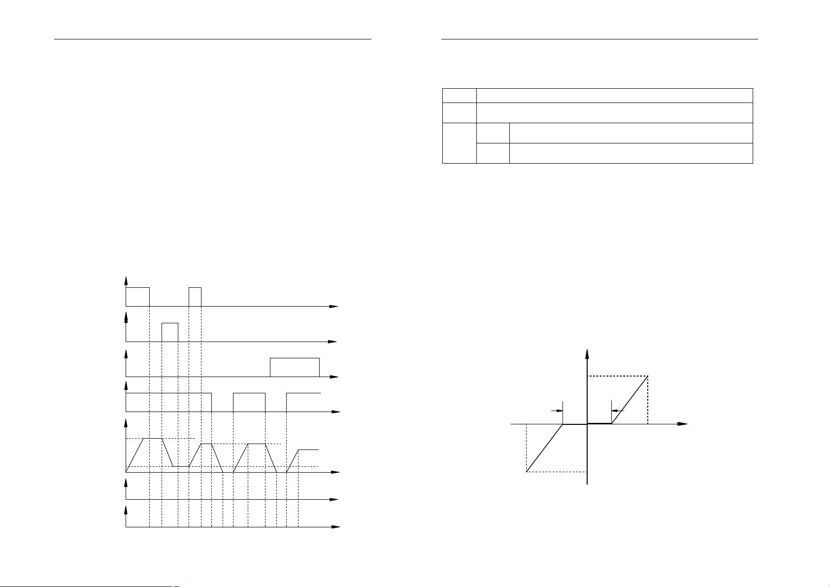
4: Ascend/Descend control:
SS1
SS2
SS3
RUN
STOP
output
frequency
upper limit
frequency
lower limit
frequency
up/down control mode 1
up/down control mode 2
F04=4
acc./dec. time
F04=13
acc./dec. time
ON
OFF
F28
OFF
ON
F09F09
F28
OFF
OFF
F10F10
F10
ON
F29
SS1,SS2 valid in high level
target frequency=
frequency before stop
F10
F09F09
F09 F09
F10
time
time
ON
time
time
target frequency=F31
setting JOG frequency
time
time
time
This function is to control ascend/descend and target frequency with the
terminals SS1, SS2, SS3.
It is OFF when SS1, SS2, SS3 are disconnected with COM, ON when they are
short circuited.
SS1
SS2
SS3
Ascend control is to change the frequency increased
Descend control is to change the frequency reduced, has
precedence over SS1
During stopping state, change the frequency caused by
ON
SS1/SS2 and turn it to F31 jog frequency
OFF
During stopping state, keep the frequency caused by
SS1/SS2
The Ascend/Descend control time in Ascend/Descend control 1 is set by
modifying F09/ F10.
The Ascend/Descend time in Ascend/Descend control 2 mode is setted by
modifing F28/F29.
5: Program Running
No limitation of the reverse forbidden. Setting value of H28~H34 and terminal
FWD/REV decide the running direction
6: Traverse running
Running by setting traverse.
7: PID adjustment running
Applicable for pressure, current close loop control.
8: Keypad potentiometer set
Frequency set by the potentiometer on the keypad.
9. V2 Forward/Reverse set
Anolog input signal V2 is to the signal to forward/reverse frequency, when V2
is larger than o01 (V2 minimum input voltage), it is the signal to forward
frequency;when V2 is smaller than o01, it is the signal to reverse frequency.
Set frequency
maximum frequency
forward
STOPSTOP
o01+0.5V
0V
o01-0.5V
reverse
o01
Maximum reverse
frequency
10. Keypad potentionmeter FWD/REV set
o02
Voltage
11: V2 proportion linkage tiny adjust
12: I2 proportion linkage tiny adjust
13: Ascend/Descend control 2
F05: Running control mode factory setting: 0
35
36
SECTION VI. FUNCTION PARAMETER DESCRIPTION
SECTION VI. FUNCTION PARAMETER DESCRIPTION
0: Keypad+RS485/CAN control
1: Keypad + terminal control+RS485/CAN control
To terminal control, edge triggers. Execute FOR/REV command in falling edge
and execute STOP command in rising edge.
Note: F62=0 is valid.
2: RS485/CAN
3: Terminal, level triggers. F62=0/1/2 is valid.
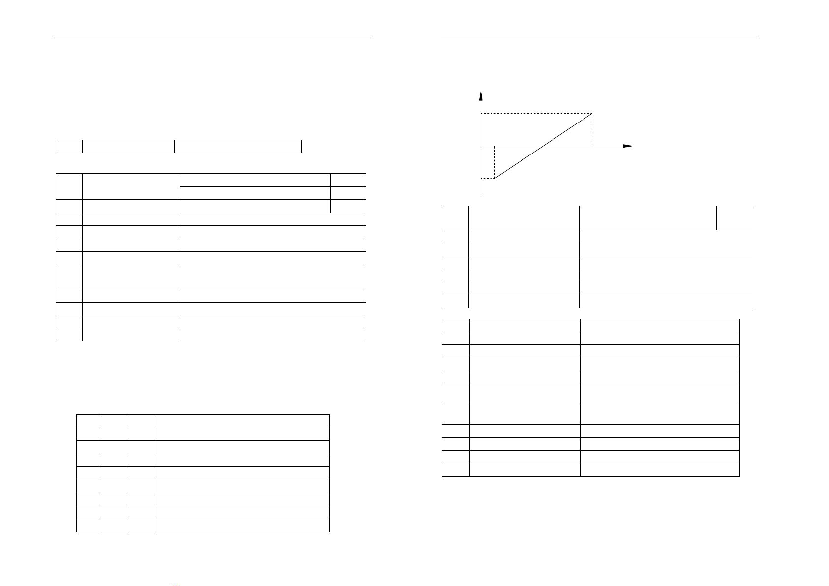
4.Proportional linkage function (improved)
For this function, the host computer should be set with the following parameters:
y12 Communication add.
128
For this function, the slave computer should be set with the following
parameters:
F04 Fre. Set mode
V2 proportional linkage adjustment 11
I2 proportional linkage adjustment 12
F05 Run control mode proportional linkage control 4
F13 Max. frequency Max. output frequency of inverter
F22 Min. running fre. Min. output frequency of inverter
y12 Communi. address 0~127
y11 Baud rate The same with that of host inverter
Proportional linkage
b15
factor
0.10~10.00
o01 V2 min. input voltage Adjustment range min. voltage
o02 V2 max. input voltage Adjustment range max voltage
o19 Min. input frequency 0.00
o20 Max. input frequency Adjustment range
υ Set 128, the inverter is the host inverter among the proportional linkage.
There is only one host inverter in one proportional linkage.
υ The F04 and F05 parameters of the host inverter can be any settings. The
running states of the slave inverters follow the host inverter.
υ If the host inverter F04=11/12, setting proportional linkage adjustment, then
F63=1 automatically, the frequency of the host inverter controlled by MSS
multi-step speed SS1/SS2/SS3.
SS3 SS2 SS1
0 0 0 Potentiometer adjustment
0 0 1 1 step speed + Potentiometer adjustment
0 1 0 2 step speed + Potentiometer adjustment
0 1 1 3 step speed + Potentiometer adjustment
1 0 0 4 step speed + Potentiometer adjustment
1 0 1 5 step speed + Potentiometer adjustment
1 1 0 6 step speed + Potentiometer adjustment
1 1 1 7 step speed + Potentiometer adjustment
The host inverter frequency
υ The host inverter controls the slave inverter’s running state.
υ The inverter set frequency=proportional linkage factor × host inverter
frequency + value adjusted by the potentiometer.
υ The range of inverter’s set frequency: F22 min. running frequency~F13
max. frequency.
o20/2
-o20/2
0
o01
(o01+o02)/2
o02
Voltage
E.g. Host inverter set:
F04 Fre. Set mode
V2 proportional linkage
adjustment
11
y12 Communi. address 128
y11 Baud rate 3
o01 V2 min. input voltage 2V
o02 V2 max. input voltage 10V
o19 Min. input frequency 0.00Hz
o20 Max. input frequency 20.00Hz
Slave inverter set:
F04 Fre. Set mode 11:V2 proportional linkage adjustment
F05 Run control mode 4
F13 Max. frequency 50.00Hz
F22 Min. running fre. 0.00Hz
y12 Communi. address 8
y11 Baud rate
Proportional linkage
b15
factor
The same with that of the host
inverter
1.00
o01 V2 min. input voltage 2V
o02 V2 max. input voltage 10V
o19 Min. input frequency 0.00Hz
o20 Max. input frequency 20.00Hz
Potentiometer adjustment range 20.00Hz
2V -10Hz
6V 0Hz
10V +10Hz
The proportional linkage wiring:
37
38
 Loading...