


Foreword
Thank you for choosing Powtran PI500 Series Frequency Inverter. This
product made by Powtran is based on years of experience in professional
production and sale, and designed for variety of industrial machinery, fan and
water pump drive unit and IF heavy-duty grinding unit.
This manual provides user the relevant precautions on installation,
operational parameter setting, abnormal diagnosis, routine maintenance and
safe use. In order to ensure correct installation and operation of the frequency
converter, please carefully read this manual before installing it.
For any problem when using this product, please contact your local dealer
authorized by this company or directly contact this company, our professionals
are happy to serve you.
The end-users should hold this manual, and keep it well for future
maintenance & care, and other application occasions. For any problem within
the warranty period, please fill out the warranty card and fax it to the our
authorized dealer.
The contents of this manual are subject to change without prior notice. To
obtain the latest information, please visit our website.
For more product information, please visit: http:// www.powtran.com.
Powtran
March , 2018

Contents
Chapter 1.Inspection and safety precautions .................................................................... 1
1-1. Inspection after unpacking ............................................................................ 1
1-1-1. Instructions on nameplate .................................................................. 1
1-1-2. Model designation ............................................................................. 1
1-2. Safety precautions ......................................................................................... 2
1-3. Precautions .................................................................................................... 3
1-4. Scope of applications ................................................................ .................... 5
Chapter 2 Standard specifications .................................................................................... 6
2-1. Technical specifications ................................................................ ................ 6
2-2. Standard specifications ................................................................................. 8
Chapter 3 Keyboard ....................................................................................................... 12
3-1. Keyboard description .................................................................................. 12
3-2. Keyboard Indicators .................................................................................... 12
3-3. Description of operation panel keys ............................................................ 13
3-4. Keyboard display letters and numbers correspondence table ...................... 13
3-5. Examples of parameter settings .................................................................. 14
3-5-1. Instructions on viewing and modifying function code ..................... 14
3-5-2. The way to read parameters in various status .................................. 15
3-5-3. Password settings ............................................................................. 15
3-5-4. Motor parameter auto turning .......................................................... 15
Chapter 4 Installation and commissioning ..................................................................... 16
4-1. Installation direction and space ................................................................... 16
4-2. Wiring Diagram .......................................................................................... 17
4-2-1. Wiring diagram ................................................................................ 18
4-3. Main circuit terminal .................................................................................. 19
4-3-1. Main circuit terminal arrangement ................................................... 19
4-3-2. Function description of main circuit terminal .................................. 22
4-4. Control circuit terminals ............................................................................. 22
4-4-1. Control circuit terminals arrangement ............................................. 22
4-4-2. Description of control circuit terminals ........................................... 22
4-5. Wiring Precautions ..................................................................................... 25
4-6. Spare Circuit ............................................................................................... 26
4-7. Commissioning ........................................................................................... 26
Chapter 5 Function parameter ........................................................................................ 28
5-1. Menu grouping ............................................................................................ 28
Chapter 6 Troubleshooting ............................................................................................. 61
6-1. Fault alarm and countermeasures ................................................................ 61
6-2. EMC (Electromagnetic Compatibility) ....................................................... 65
6-2-1. Definition ......................................................................................... 65

6-2-2. EMC standard.................................................................................. 65
6-3. EMC directive ............................................................................................ 65
6-3-1. Harmonic effect ............................................................................... 65
6-3-2. Electromagnetic interference and installation precautions .............. 65
6-3-3. Remedies for the interference from the surrounding electromagnetic
equipment to the inverter ............................................................... 66
6-3-4. Remedies for the interference from the inverter to the surrounding
electromagnetic equipment ............................................................ 66
6-3-5. Remedies for leakage current .......................................................... 66
6-3-6. Precautions on installing EMC input filter at the input end of power
supply ............................................................................................. 67
Chapter 7 Dimension ..................................................................................................... 68
7-1. Dimension .................................................................................................. 68
7-1-1. Product outside drawing, installation size ....................................... 68
7-1-2. PI500 series ..................................................................................... 68
7-1-3. PI500 series (With DC reactor base) ................................ ............... 73
7-1-4. Keypad dimension drawing ............................................................. 76
Chapter 8 Maintenance and repair ................................................................................. 78
8-1. Inspection and maintenance........................................................................ 78
8-2. Parts for regular replacement ...................................................................... 78
8-3. Storage........................................................................................................ 79
8-4. Capacitor .................................................................................................... 79
8-4-1. Capacitor rebuilt .............................................................................. 79
8-5. Measuring and readings .............................................................................. 80
Chapter 9 Options .......................................................................................................... 81
Chapter 10 Warranty ................................................................................................ ...... 83
Appendix I RS485 Communication protocol ................................................................ 84
I-1 Communication protocol ........................................................................... 84
I-1-1 Communication content ................................................................. 84
I-1-2 Protocol description ....................................................................... 85
I-3 Definition of communication parameter address .......................................... 88
Appendix II How to use universal encoder expansion card ........................................... 93
III-2 Description of mechanical installation and control terminals
function .................................................................................................... 93
Appendix III CAN bus communication card use description ........................................ 95
IV-1.Overview ................................................................................................... 95
IV2.Mechanical installation and terminal functions .......................................... 95
Appendix IV: Instruction of Profitbus –DP communication card .................................. 96
IV-1.Outline ....................................................................................................... 96
IV-2 Terminal function ...................................................................................... 96
Appendix V product application case ............................................................................ 98
3

V-1. Single pump constant pressure water supply parameter setting ................. 98
V-2 terminal block control motor forward and reverse ...................................... 99
V-3 external frequency table and ammeter......................................................... 99
V-4 Terminal block control forward /reverse running jog ............................... 100
V-5 Multi-speed running .................................................................................. 101
V-6 External potentiometer speed .................................................................... 102
V-7 Keyboard potentiometer speed .................................................................. 103
V-8. Rise / Fall Control Speed ......................................................................... 103
V-9. External analog speed control (external 0 ~ 10V voltage signal
given) ..................................................................................................... 104
V-10. External analog speed control (external 0 ~ 20mA current signal
given) ..................................................................................................... 104
V-11. Air compressor constant pressure control (sensor for two-wire
pressure transmitter) ............................................................................... 105
V-12.frequency reference mode(external potentiometer, keyboard
encoder) switching ................................................................................. 107
第
十
Chapter 1
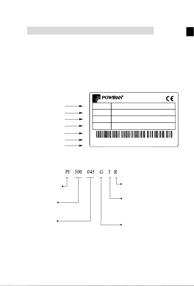
*Input Source Spec.
*Output Power Spec.
*Production Sequence
Number
*POWTRAN
Inverter model
POWER
INPUT
OUTPUT
DALIAN POWTRAN TECHNOLOGY CO.,LTD.
MODEL
45kW
AC 3PH 380V(-15%) ~440V(+10%) 50Hz/60Hz
AC 3PH 0V~Vin 90A 0~400Hz
PI500 045G3
ZPB1A8888888
*Output Spec.
*Bar code
*Production Address
POWTRAN Inverter
Rated output capacity
045: 45kW
132: 132kW
Series Code
PI500 Series
Input Voltage Level
1: Single-phase 220V
2: Three-phase 220V
3: Three-phase 380V
4: Three-phase 480V
6: Three-phase 690V
Code with DC reactance
R: with DC reactor
(don't write without DC reactance)
Function code
F: Light load
G: Standard load
Chapter 1.Inspection and safety precautions
Powtran
purchasing, please check if its package is damaged due to careless transportation, and if the
specifications and model of the product are consistent with your order requirements. For any
problem, please contact your local authorized
1-1.Inspection after unpacking
※ Check if that packing container contains this unit, one manual and one warranty card.
※ Check the nameplate on the side of the frequency inverter to ensure that the product you
1-1-1.Instructions on nameplate
frequency inverters have been tested and inspected before leaving factory. After
Powtran
dealer or directly contact this company.
have received is right the one you ordered.
Figure 1-1:Nameplate Description
1-1-2.Model designation
Figure 1-2:Model Description
1
Chapter 1.Inspection and safety precautions
Chapter 1
Process
Type
Explanation
Before
installation
Danger
●When unpacking, if control system with water, parts missed or
component damaged are found, do not install!
●If packing list does not match the real name, do not install!
When
installing
Danger
● Gently carry with care, otherwise there is the risk of damage to
equipment!
●Please do not use the damaged driver or the frequency inverter
with missed pieces, otherwise there is the risk of injury!
●Do not use your hand to touch the control system components,
otherwise there is the risk of electrostatic damage!
Note
● Please install the unit on the metal or flame retardant objects;
away from combustible material. Failure to do so may cause a fire!
● Never twist the mounting bolts of the equipment components,
especially the bolt with the red mark!
When
wiring
Danger
● Do not let the lead wires or screws fall into the driver. Otherwise
which may cause damage to the driver!
● Keep the driver installed in the place where less vibration, avoid
direct sunlight.
● When two or more converters are installed in a cabinet, please
pay attention to the installation location, ensure the good heat
dissipation effect.
Before
energizing
Note
● Must comply with this manual's guidance, any construction shall
be performed by a professional electrician, otherwise there would
be the unexpected risk !
● A circuit breaker must be set between the inverter and the power
supply to separate them, otherwise it may cause a fire!
Danger
● Verify if power is a zero-energy status before wiring, otherwise
there is a risk of electric shock!
● The inverter shall be grounded correctly according to standard
specifications, otherwise there is a danger of electrical shock!
● Ensure that the distribution line meets the regional safety
standards of EMC requirements. The diameter of used wire shall
refer to the recommendations of this manual. Otherwise it may
cause an accident!
● Never directly connect braking resistor to the DC bus P(+) and
P(-) terminals. Otherwise it may cause a fire!
● Encoder must use the shielded wire, and the shielding layer must
ensure the single-ended grounded!
After
energizing
Danger
● Please confirm whether the input power voltage is same as the
inverter rated voltage; wiring positions of power input terminals(R,
S, T) and output terminals(U, V, W) are correct or not; and note
that if there is a short circuit in the peripheral circuit connected to
driver, if the connected lines are tight, otherwise it may cause
damage to the driver!
● Do not need to perform withstand voltage test for any part of the
inverter, this product has been tested before leaving factory.
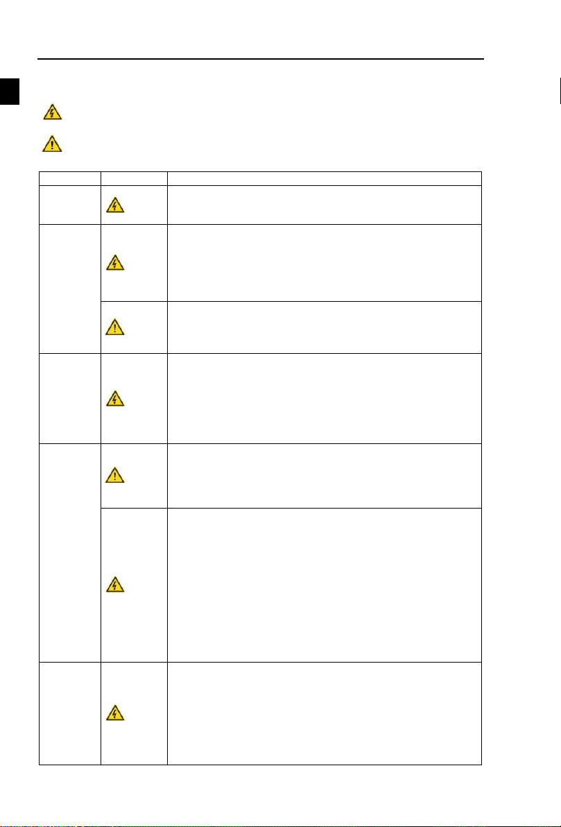
1-2.Safety precautions
Safety precautions in this manual are divided into the following two categories:
Danger: the dangers caused by failure to perform required operation, may result in serious
injury or even death;
Caution:the dangers caused by failure to perform required operation, may result in moderate
injury or minor injury, and equipment damage;
2

Chapter 1.Inspection and safety precautions
Chapter 1
Otherwise it may cause an accident!
During
operation
Danger
● The inverter's cover plate must be closed before power on.
Otherwise it may cause an electric shock!
● Wiring of all external accessories must comply with the guidance
of this manual, please correctly wiring in accordance with the
circuit connection methods described in this manual. Otherwise it
may cause an accident!
Note
● Do not open cover plate after energizing. Otherwise there is a
risk of electric shock!
● Do not touch the driver and peripheral circuits with wet hands.
Otherwise there is a risk of electric shock!
● Do not touch any input and output terminals of the inverter.
Otherwise there is a risk of electric shock!
● The inverter automatically perform the safety testing for the
external strong electrical circuit in the early stages of energizing,
therefore never touch the driver terminals(U, V, W) or motor
terminals, otherwise there is a risk of electric shock!
● If you need to identify the parameters, please pay attention to the
danger of injury during motor rotation. Otherwise it may cause an
accident!
● Please do not change the inverter manufacturer parameters.
Otherwise it may cause damage to this unit!
When
maintaining
Danger
● Do not touch the cooling fan and the discharge resistor to feel the
temperature. Otherwise it may cause burns!
● Non-professional personnel is not allowed to detect signal when
operating. Doing so may cause personal injury or damage to this
unit!
● When the inverter is operating, you should avoid that objects fall
into this unit.Otherwise cause damage to this unit!
● Do not start/stop the driver by switching on/off contactor.
Otherwise cause damage to this unit!
● Do not perform repairs and maintenance for the live electrical
equipment. Otherwise there is a risk of electric shock!
● The repairs and maintenance task can be performed only when
the inverter bus voltage is lower than 36V,Otherwise, the residual
charge from capacitor would cause personal injury!
● Non-well-trained professional personnel is not allowed to
perform repairs and maintenance of inverter. Doing this may cause
personal injury or damage to this unit!
● After replacing the inverter, parameter settings must be redone,
all pluggable plugs can be operated only in the case of powering
off!
No.
Type
Explanation
1
Motor insulation
inspection
Please perform motor insulation inspection for the first time use,
re-use after leaving unused for a long time as well as regular
check, in order to prevent damage to the inverter because of the
motor's winding insulation failure. Wiring between motor and
inverter shall be disconnected, it is recommended that the 500V
voltage type megger should be adopted and insulation resistance
shall be not less than 5MΩ.
2
Motor thermal
protection
If the rated capacity of the selected motor does not match the
inverter, especially when the inverter rated power is greater than
1-3.Precautions
3

Chapter 1.Inspection and safety precautions
Chapter 1
the motor rated power, be sure to adjust the motor protection
parameter values inside inverter or install thermal relay in the front
of motor for motor protection.
3
Run over power
frequency
The inverter output frequency rang is 0Hz to 3200Hz(Max.vector
control only supports 300Hz). If the user is required to run at 50Hz
or more, please consider the endurance of your mechanical
devices.
4
Vibrations of
mechanical device
Inverter output frequency may be encountered mechanical
resonance point of the load device, you can set jump frequency
parameter inside inverter to avoid the case.
5
Motor heat and
noise
The inverter output voltage is PWM wave that contains a certain
amount of harmonics, so the temperature rise, noise and vibration
of motor show a slight higher than frequency power frequency
operation.
6
Output side with
piezoresistor or
capacitor for proving
power factor
The inverter output is PWM wave, if the piezoresistor for lightning
protection or the capacitor for improving power factor is installed
in the output side, which easily cause the inverter instantaneous
overcurrent or even cause damage to the inverter. Please do not
use.
7
Contactor or switch
used in the inverter
input/output
terminals
If contactor is installed between power supply and inverter, the
contactor is not allowed to start/stop the inverter. Necessarily need
to use the contactor to control the inverter start/stop, the interval
should not be less than one hour. Frequent charging and
discharging may reduce the service life of the inverter capacitor. If
the contactor or switch is equipped between output terminals and
motor, the inverter should be turned on/off without output status,
otherwise which easily lead to damage to the inverter module.
8
Use other than the
ratedvoltage
PI series inverter is not suitable for use beyond the allowable
operating voltage described in this manual, which easily cause
damage to the parts inside inverter. If necessary, please use the
corresponding transformer to change voltage.
9
Never change 3phase input to 2phase input
Never change PI series 3-phase inverter to 2-phase one for
application. Otherwise it will lead to malfunction or damage to the
inverter.
10
Lightning surge
protection
The series inverter is equipped with lightning overcurrent
protection device, so it has the ability of self-protection to
lightning induction. For the area where lightning is frequent, user
should also install the extra protection in the front of the inverter.
11
High altitude and
derating application
When the inverter is used in areas over 1000m altitude, it is
required to reduce frequency because the thin air will decrease the
cooling effect of inverter. Please consult our technician for details
on the application.
12
Special use
If the user need to use methods other than the suggested wiring
diagram provided in this manual, such as common DC bus, please
consult our technician.
13
Precautions for scrap
disposal of the
inverter
When electrolytic capacitors on the main circuit and printed circuit
board as well as plastic parts are burned, it may produce toxic
gases.Please disposing as industrial waste.
14
Adaptive motor
1) Standard adaptive motor shall be four-pole asynchronous
squirrel-cage induction motor or permanent magnet synchronous
motor. Apart from the said motors, please select the inverter
according to the motor rated current.
2) The cooling fan and the rotor shaft for non-inverter motor are
coaxially connected, the fan cooling effect is reduced when the
4

Chapter 1.Inspection and safety precautions
Chapter 1
rotational speed is reduced, therefore, when the motor works in
overheating occasions, a strong exhaust fan should be retrofitted or
replace non-inverter motor with the inverter motor.
3) The inverter has built-in the adaptive motor standard
parameters, according to the actual situation, please identify motor
parameters or accordingly modify the default values to try to meet
the actual value, otherwise it will operation affect and protection
performance;
4) When short-circuit of cable or motor internal will activate the
inverter alarm, even bombing. Therefore, firstly perform insulation
short-circuit test for the initial installation of the motor and cable,
routine maintenance often also need to perform such test. Note that
the parts to be tested and the inverter shall be disconnected
completely when testing.
15
Others
1)We need to fix cover and lock before power on, so as to avoid the
harm to personal safety that is caused by internal injuries of bad
capacitors and other components.
2)Do not touch internal circuit board and any parts after powering
off and within five minutes after keyboard indicator lamp goes out,
you must use the instrument to confirm that internal capacitor has
been discharged fully, otherwise there is a danger of electric shock.
3)Body static electricity will seriously damage the internal MOS
field-effect transistors, etc., if there are not anti-static measures, do
not touch the printed circuit board and IGBT internal device with
hand, otherwise it may cause a malfunction.
4)The ground terminal of the inverter(E or ) shall be earthed
firmly according to the provisions of the National Electrical Safety
and other relevant standards. Do not shut down(power off) by
pulling switch, and only cut off the power until the motor stopping
operation.
5)It is required to add the optional input filter attachment so as to
meet CE standards.
Only the well-trained personnel can be allowed to operate this unit, please carefully
read the instre1tions on safety, installation, operation and maintenance before use.
The safe operation of this unit depends on proper transport, installation, operation
and maintenance!
1-4.Scope of applications
※ This inverter is suitable for three-phase AC asynchronous motor and permanent magnet
synchronous motor.
※ This inverter can only be used in those occasions recognized by this company, an
unapproved use may result in fire, electric shock, explosion and other accidents.
※ If the inverter is used in such equipment (e.g: equipment for lifting persons, aviation systems,
safety equipment, etc.) and its malfunction may result in personal injury or even death. In
this case, please consult the manufacturer for your application.
5

第
十
Chapter 2
Model
Rated output
power(kW)
Rated input
current(A)
Rated
output
current(A)
Adaptive
motor(kW)
AC 1PH 220V(-15%)~240V(+10%)
PI500 0R4G1
0.4
5.4
2.5
0.4
PI500 0R7G1
0.75
8.2 4 0.75
PI500 1R5G1
1.5
14 7 1.5
PI500 2R2G1
2.2
23
10
2.2
PI500 004G1
4.0
35
16
4.0
PI500 5R5G1
5.5
50
25
5.5
AC 3PH 220V(-15%)~240V(+10%)
PI500 0R4G2
0.4
4.1
2.5
0.4
PI500 0R7G2
0.75
5.3 4 0.75
PI500 1R5G2
1.5
8.0 7 1.5
PI500 2R2G2
2.2
11.8
10
2.2
PI500 004G2
4.0
18.1
16 4 PI500 5R5G2
5.5
28
25
5.5
PI500 7R5G2
7.5
37.1
32
7.5
PI500 011G2
11
49.8
45
11
PI500 015G2
15.0
65.4
60
15.0
PI500 018G2
18.5
81.6
75
18.5
PI500 022G2
22.0
97.7
90
22.0
PI500 030G2
30.0
122.1
110
30.0
PI500 037G2
37.0
157.4
152
37.0
PI500 045G2
45.0
185.3
176
45.0
PI500 055G2
55.0
214
210
55.0
PI500 075G2
75
307
304
75
PI500 093G2
93
383
380
93
PI500 110G2
110
428
426
110
PI500 132G2
132
467
465
132
PI500 160G2
160
522
520
160
AC 3PH 380V(-15%)~440V(+10%)
PI500 0R7G3
0.75
4.3
2.5
0.75
PI500 1R5G3
1.5
5.0
3.8
1.5
PI500 2R2G3
2.2
5.8
5.1
2.2
PI500 004G3
4.0
10.5 9 4.0
PI500 5R5G3
5.5
14.6
13
5.5
PI500 7R5G3
7.5
20.5
17
7.5
PI500 011F3
11
26
25
11
PI500 011G3
11
26
25
11
PI500 015F3
15
35
32
15
PI500 015G3/PI500 018F3
15/18.5
35/38.5
32/37
15/18.5
PI500 018G3/PI500 022F3
18.5/22
38.5/46.5
37/45
18.5/22
PI500 022G3/PI500 030F3
22/30
46.5/62
45/60
22/30
PI500 030G3/PI500 037F3
30/37
62/76
60/75
30/37
PI500 037G3/PI500 045F3
37/45
76/91
75/90
37/45
PI500 045G3N
45
91
90
45
Chapter 2 Standard specifications
2-1.Technical specifications
6

Chapter 2 Standard specifications
Chapter 2
PI500 045G3/PI500 055F3
45/55
91/112
90/110
45/55
PI500 055G3
55
112
110
55
PI500 075F3
75
157
150
75
PI500 075G3
75
157
150
75
PI500 093F3
93
180
176
93
PI500 093G3/PI500 110F3
93/110
180/214
176/210
93/110
PI500 110G3/PI500 132F3
110/132
214/256
210/253
110/132
PI500 132G3/PI500 160F3
132/160
256/307
253/304
132/160
PI500 160G3/PI500 187F3
160/187
307/345
304/340
160/187
PI500 187G3/PI500 200F3
187/200
345/385
340/380
187/200
PI500 200G3/PI500 220F3
200/220
385/430
380/426
200/220
PI500 220G3
220
430
426
220
PI500 250F3
250
468
465
250
PI500 250G3/PI500 280F3
250/280
468/525
465/520
250/280
PI500 280G3
280
525
520
280
PI500 315F3
315
590
585
315
PI500 315G3/PI500 355F3
315/355
590/665
585/650
315/355
PI500 355G3/PI500 400F3
355/400
665/785
650/725
355/400
PI500 400G3
400
785
725
400
PI500 450F3R
450
883
820
450
PI500 450G3R/PI500 500F3R
450/500
883/920
820/860
450/500
PI500 500G3R/PI500 560F3R
500/560
920/1010
860/950
500/560
PI500 560G3R/PI500 630F3R
560/630
1010/1160
950/1100
560/630
PI500 630G3R/PI500 700F3R
630/700
1160/1310
1100/1250
630/700
AC 3PH 480V±10%
PI500 0R7G4
0.75
4.1
2.5
0.75
PI500 1R5G4
1.5
4.9
3.7
1.5
PI500 2R2G4
2.2
5.7
5.0
2.2
PI500 004G4
4.0
9.4 8 4.0
PI500 5R5G4
5.5
12.5
11
5.5
PI500 7R5G4
7.5
18.3
15
7.5
PI500 011F4
11
23.1
22
11
PI500 011G4
11
23.1
22
11
PI500 015F4
15
29.8
27
15
PI500 015G4/PI500 018F4
15/18.5
29.8/35.7
27/34
15/18.5
PI500 018G4/PI500 022F4
18.5/22
35.7/41.7
34/40
18.5/22
PI500 022G4/PI500 030F4
22/30
41.7/57.4
40/55
22/30
PI500 030G4/PI500 037F4
30/37
57.4/66.5
55/65
30/37
PI500 037G4/PI500 045F4
37/45
66.5/81.7
65/80
37/45
PI500 045G4N
45
81.7
80
45
PI500 045G4/PI500 055F4
45/55
81.7/101.9
80/100
45/55
PI500 055G4
55
101.9
100
55
PI500 075F4
75
137.4
130
75
PI500 075G4
75
137.4
130
75
PI500 093F4
93
151.8
147
93
PI500 093G4/PI500 110F4
93/110
151.8/185.3
147/180
93/110
PI500 110G4/PI500 132F4
110/132
185.3/220.7
180/216
110/132
PI500 132G4/PI500 160F4
132/160
220.7/264.2
216/259
132/160
PI500 160G4/PI500 187F4
160/187
264.2/309.4
259/300
160/187
PI500 187G4/PI500 200F4
187/200
309.4/334.4
300/328
187/200
PI500 200G4/PI500 220F4
200/220
334.4/363.9
328/358
200/220
PI500 220G4
220
363.9
358
220
7

Chapter 2 Standard specifications
Chapter 2
PI500 250F4
250
407.9
400
250
PI500 250G4/PI500 280F4
250/280
407.9/457.4
400/449
250/280
PI500 280G4
280
457.4
449
280
PI500 315F4
315
533.2
516
315
PI500 315G4/PI500 355F4
315/355
533.2/623.3
516/570
315/355
PI500 355G4/PI500 400F4
355/400
623.3/706.9
570/650
355/400
PI500 400G4
400
706.9
650
400
AC 3PH 690V±10%
PI500 011G6/ PI500 015F6
11/15
15/20
12/15
11/15
PI500 015G6/ PI500 018F6
15/18.5
20/30
15/20
15/18.5
PI500 018G6/ PI500 022F6
18.5/22
30/35
20/24
18.5/22
PI500 022G6/ PI500 030F6
22/30
35/45
24/33
22/30
PI500 030G6/ PI500 037F6
30/37
45/55
33/41
30/37
PI500 037G6/ PI500 045F6
37/45
55/65
41/50
37/45
PI500 045G6/ PI500 055F6
45/55
65/70
50/62
45/55
PI500 055G6/ PI500 075F6
55/75
70/90
62/85
55/75
PI500 075G6/ PI500 093F6
75/93
90/105
85/102
75/93
PI500 093G6/ PI500 110F6
93/110
105/130
102/125
93/110
PI500 110G6/ PI500 132F6
110/132
130/170
125/150
110/132
PI500 132G6/ PI500 160F6
132/160
170/200
150/175
132/160
PI500 160G6/ PI500 187F6
160/187
200/210
175/198
160/187
PI500 187G6/ PI500 200F6
187/200
210/235
198/215
187/200
PI500 200G6/ PI500 220F6
200/220
235/247
215/245
200/220
PI500 220G6/ PI500 250F6
220/250
247/265
245/260
220/250
PI500 250G6/ PI500 280F6
250/280
265/305
260/299
250/280
PI500 280G6/ PI500 315F6
280/315
305/350
299/330
280/315
PI500 315G6/ PI500 355F6
315/355
350/382
330/374
315/355
PI500 355G6/ PI500 400F6
355/400
382/435
374/410
355/400
PI500 400G6/ PI500 450F6
400/450
435/490
410/465
400/450
Items
Specifications
Power Input
Rated voltage
AC 1PH 220V(-15%)~240V(+10%)
AC 3PH 220V(-15%)~240V(+10%)
AC 3PH 380V(-15%)~440V(+10%)
AC 3PH 480V(-10%)~480V(+10%)
AC 3PH 690V(-10%)~690V(+10%)
Input frequency
50Hz/60Hz
Allowing
fluctuations
Voltage continued
volatility:±10%
Less than 3% of voltage unbalance rate
3%;
Input frequency
fluctuation:±5%;
Distortion satisfy IEC61800-2 standard
Note:
(1)PI500 inverter PI500 132G3/PI500 160F3 to PI500 630G3R/PI500 700F3R with "R"
indicating a DC reactor, such as PI500-160G3R, PI500 160G4R.
(2) The correct frequency converter selection method is: inverter rated output current is more
than or equal to the rated current of motor. The difference between the frequency inverter and the
rated power of the motor generally recommends no more than two power segments;Large
frequency inverter with small motor, must accurately input motor parameters, can avoid motor
overload and damage.
2-2.Standard specifications
8

Chapter 2 Standard specifications
Chapter 2
Control system
Control system
High performance vector control inverter based on DSP
Control method
V/F control, vector control W/O PG, vector control W/ PG
Automatic torque
boost function
Realize low frequency (1Hz) and large output torque control under the
V/F control mode.
Acceleration/decel
eration control
Straight or S-curve mode. Four times available and time range is 0.0 to
6500.0s.
V/F curve mode
Linear, square root/m-th power, custom V/F curve
Over load
capability
G type:rated current 150% - 1 minute, rated current 180% - 2 seconds
F type:rated current 120% - 1 minute, rated current 150% - 2 seconds
Maximum
frequency
1、Vector control:0 to 300Hz; 2、V/F control:0 to 3200Hz
Carrier Frequency
0.5 to 16kHz; automatically adjust carrier frequency according to the
load characteristics.
Input frequency
resolution
Digital setting: 0.01Hz minimum analog: 0.01Hz.
Start torque
G type: 0.5Hz/150% (vector control W/O PG)
F type: 0.5Hz/100% (vector control W/O PG)
Speed range
1:100 (vector control W/O PG) 1:1000 (vector control W/ PG)
Steady-speed
precision
Vector control W/O PG: ≤ ± 0.5% (rated synchronous speed)
Vector control W/ PG: ≤ ± 0.02% (rated synchronous speed)
Torque response
≤ 40ms (vector control W/O PG)
Torque boost
Automatic torque boost; manual torque boost(0.1% to 30.0%)
DC braking
DC braking frequency: 0.0Hz to max. frequency, braking time:
0.0 to 100.0 seconds, braking current value: 0.0% to 100.0%
Jogging control
Jog Frequency Range: 0.00Hz to max. frequency;
Jog Ac/deceleration time: 0.0 to 6500.0s
Multi-speed
operation
Achieve up to 16-speed operation through the control terminal
Built-in PID
Easy to realize closed-loop control system for the process control.
Automatic voltage
regulation(AVR)
Automatically maintain a constant output voltage when the voltage of
electricity grid changes
Torque limit and
control
"Excavator" feature - torque is automatically limited during the
operation to prevent frequent overcurrent trip; the closed-loop vector
mode is used to control torque.
Personalization function
Self-inspection of
peripherals after
power-on
After powering on, peripheral equipment will perform safety testing,
such as ground, short circuit, etc.
Common DC bus
function
Multiple inverter can use a common DC bus.
Quick current
limiting
The current limiting algorithm is used to reduce the inverter over
current probability, and improve whole unit anti-interference capability.
Timing control
Timing control function: time setting range(0m to 6500m)
Running
Input
signal
Running
method
Keyboard/terminal/communication
Frequency
10 frequency settings available, including adjustable DC(0~10V/-10~
9

Chapter 2 Standard specifications
Chapter 2
setting
+10V), adjustable DC(0 to 20mA), panel potentiometer, etc.
Start signal
Rotate forward/reverse
Multi-speed
At most 16-speed can be set(run by using the multi-function terminals
or
program
)
Emergency
stop
Interrupt
controller output
Wobbulate run
Process
control run
Fault reset
When the protection function is active, you can automatically or
manually
reset the fault condition.
PID feedback
signal
Including
DC(0 to 10V), DC(0 to 20mA)
Output Signal
Running status
Motor
status
display, stop, ac/deceleration, constant speed, program
running status.
Fault output
Contact capacity :normally closed contact 3A/AC 250V,normally
open
contact5A
/AC 250V,1A/DC 30V.
Analog output
Two-way analog output, 16 signals can be selected such as frequency,
current
, voltage and other, output signal range (0 to 10V / 0 to 20mA).
Output signal
At most 4-way output, there are 40 signals each way
Run function
Limit frequency, jump frequency, frequency compensation, auto-tuning,
PID control
DC current
braking
Built-in PID regulates braking current to ensure sufficient braking
torque under no overcurrent condition.
Running
command channel
Three channels: operation panel, control terminals and serial
communication port. They can be switched through a variety of ways.
Frequency source
Total 10 frequency sources: digital, analog voltage, analog current,
multi-speed and serial port. They can be switched through a variety of
ways.
Input terminals
8 digital input terminals, compatible with active PNP or NPN input
mode, one of them can be for high-speed pulse input(0 to 100 kHz
square wave); 3 analog input terminals for voltage or current input.
Output terminals
2 digital output terminals, one of them can be for high-speed pulse
output(0 to 100kHz square wave); one relay output terminal; 2 analog
output terminals respectively for optional range (0 to 20mA or 0 to
10V), they can be used to set frequency, output frequency, speed and
other physical parameters.
Protection function
Inverter protection
Overvoltage protection, undervoltage protection, overcurrent
protection, overload protection, overheat protection, overcurrent stall
protection, overvoltage stall protection, losting-phase protection
(optional), communication error, PID feedback signal abnormalities,
PG failure and short circuit to ground protection.
IGBT temperature
display
Displays current temperature IGBT
Inverter fan control
Can be set
Instantaneous
power-down restart
Less than 15 milliseconds: continuous operation.
More than 15 milliseconds: automatic detection of motor speed,
instantaneous power-down restart.
10

Chapter 2 Standard specifications
Chapter 2
Speed start tracking
method
The inverter automatically tracks motor speed after it starts
Parameter
protection function
Protect inverter parameters by setting administrator Password and
decoding
Display
LED/O
LED
display
keyboa
rd
Running
informatio
n
Monitoring objects including: running frequency, set frequency, bus
voltage, output voltage, output current, output power, output torque,
input terminal status, output terminal status, analog AI1 value, analog
AI2 value, motor Actual running speed,PID set value percentage, PID
feedback value percentage.
Error
message
At most save three error message, and the time, type, voltage, current,
frequency and work status can be queried when the failure is occurred.
LED display
Display parameters
OLED display
Optional, prompts operation content in Chinese/English text.
Copy parameter
Can upload and download function code information of frequency
converter, rapid replication parameters.
Key lock and
function selection
Lock part or all of keys, define the function scope of some keys to
prevent misuse.
Com
muni
catio
n
RS485
The optional completely isolated RS485 communication module can
communicate with the host computer.
Environment
Product standard
Environment
temperature
-10to 40℃ (The environment temperature in 40 ~ 50 ℃, please
derating use)
Storage
temperature
-20 to 65 ℃
Environment
humidity
Less than 90% R.H, no condensation.
Vibration
Below 5.9m/s² (= 0.6g)
Application sites
Indoor where no sunlight or corrosive, explosive gas and water vapor,
dust, flammable gas,oil mist, water vapor, drip or salt, etc.
Altitude
No need derating below 1000m, please derating 1% every 100 m when
the altitude is above 3000m
Protection level
IP20
Product
standard
Product adopts
safety standards.
IEC61800-5-1:2007
Product adopts
EMC standards.
IEC61800-3:2005
Cooling method
Forced air cooling
11
第
十
Chapter 3
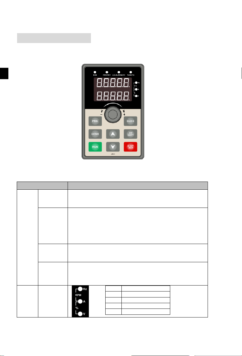
Indicator
flag
Name
Status lamp
RUN
Running indicator light
* ON: the inverter is working
* OFF: the inverter stops
LOCAL/R
EMOTE
Command indicator light
That is the indicator for keyboard operation, terminal operation and
remote operation (communication control)
* ON: terminal control working status
* OFF: keyboard control working status
* Flashing: remote control working status
FWD/REV
Forward/reverse running light
* ON: in forward status
* OFF: in reversal status
TUNE/TC
Motor self-learning/Torque control/Fault indicator
* ON: in torque control mode
* Slow flashing: in the motor tunning status
* Quick flashing: in the fault status
Units
combinatio
n indicator
HzAV
Hz
frequency unit
A
current unit
V
voltage unit
RPM
speed unit
%
percentage
Chapter 3 Keyboard
3-1.Keyboard description
Figure 3-1:Operation panel display
3-2.Keyboard Indicators
12
Chapter 3
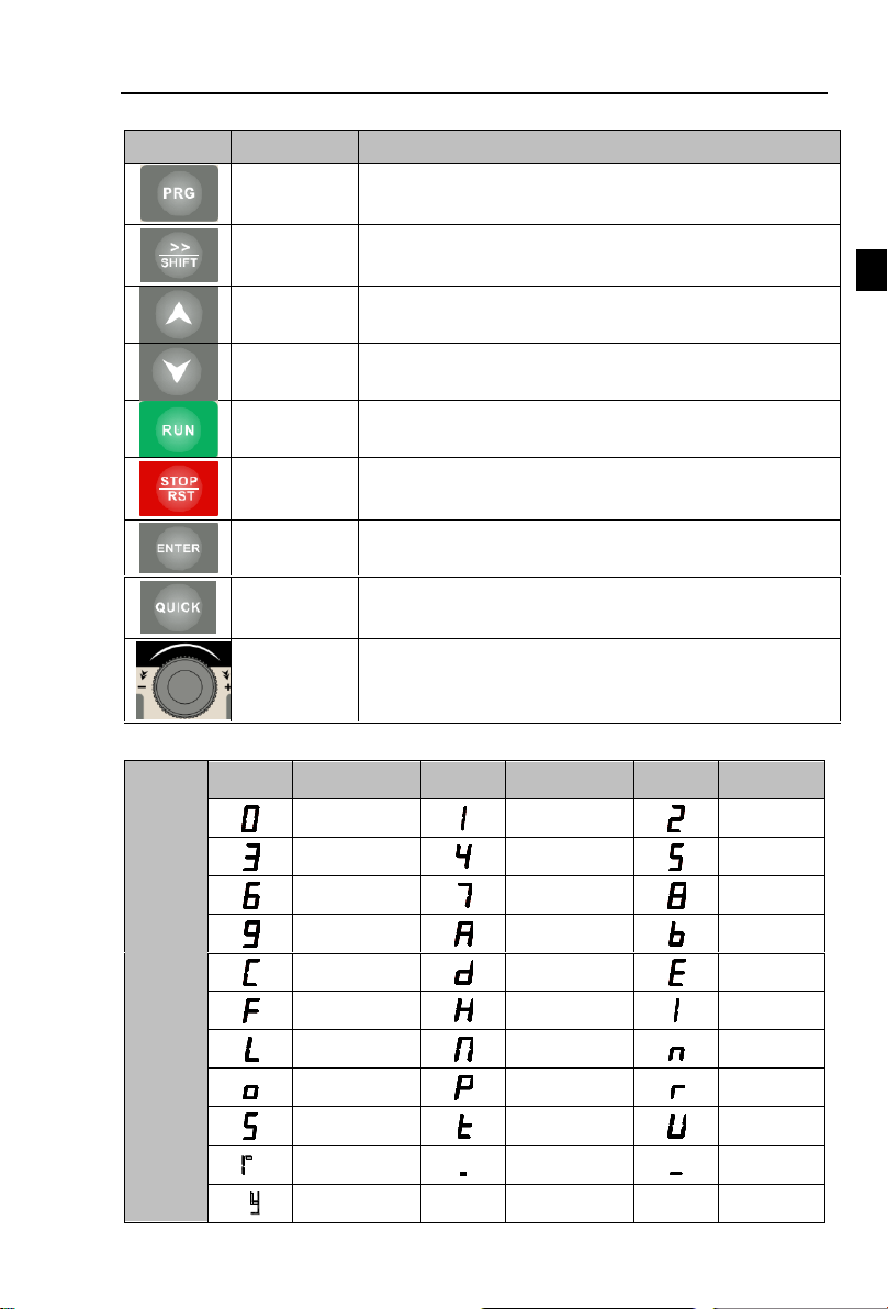
3-3.Description of operation panel keys
Sign
Name
Function
Parameter
Setting/Esc
Key
* Enter into the modified status of main menu
* Esc from functional parameter modification
* Esc submenu or functional menu to status menu
Shift Key
*Choose displayed parameter circularly under running or stop
interface; choose parameter’s modified position when modify
parameter
Increasing Key
Parameter or function number increasing,set by parameter F6.18.
Decreasing
key
Parameter or function number decreasing, set by parameter
F6.19.
Running key
For starting running in the mode of keyboard control status
Stop/Reset
Key
*For stopping running in the running status; for resetting the
operation in fault alarm status. The function of the key is subject
to F6.00
Enter key
Enter into levels of menu screen confirm setting
Quick
multifunction
key
This key function is determined by the function code F6.21.
Keyboard
encoder
* In query
status
, function parameter increasing or decreasing
* In modified status, the function parameter or modified
position
increasing or decreasing.
* In monitoring status, frequency setting increasing or decreasing
Digital
display
area
Display
letters
Corresponding
letters
Display
letters
Corresponding
letters
Display
letters
Correspondi
ng letters
0 1 2 3 4 5 6 7 8 9 A B
C d E
F H I L
N n o P r S t U T . -
y
Chapter 3 Keyboard
3-4.Keyboard display letters and numbers correspondence table
13
Chapter 3 Keyboard
Chapter 3
Shutdown parameter display
PRG
Change parameter group
PRG
First-level menu display
ENTER
Change function parameter selection
PRG
ENTER
Change function parameter value
PRG
ENTER
Power-on
Second-level menu display
Third-level menu display
Press PRG
Press ENTER
Press ▲
Press ▼
Press ENTER
Press PRG
Press PRG
Press ENTER
Flicker
Flicker
Flicker
Flicker
Flicker
Flicker
Press ▲
Press PRG
Press ENTER
Flicker
Flicker
Flicker
Flicker
Press PRG
Press ENTER
Press ▲
Press ENTER
Press PRG
3-5.Examples of parameter settings
3-5-1.Instructions on viewing and modifying function code
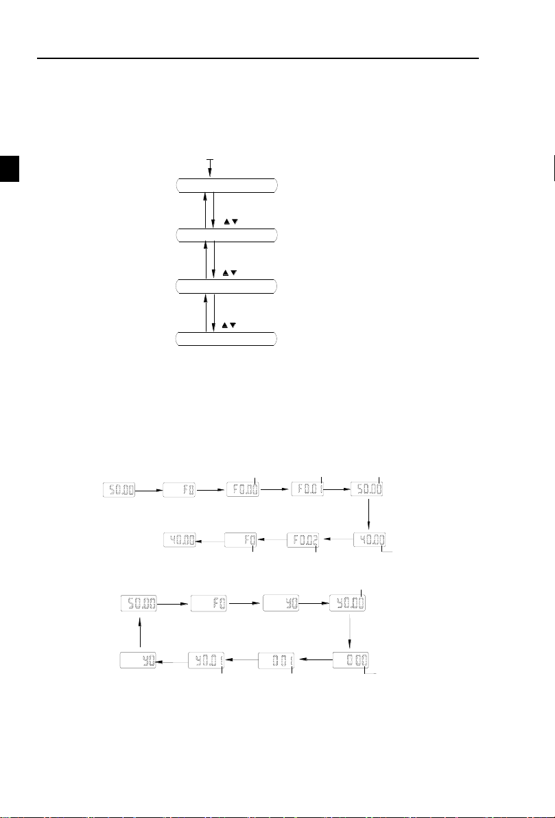
PI500 inverter’s operation pane is three levels menu for parameter setting etc.Three levels:
function parameter group (Level 1)→function code(level 2)→function code setting(level 3). The
operation is as following:
Description: Back to the level 2 menu from level 3 menu by PRG key or ENTER key in the
level 3 operation status. The differences between the two keys : ENTER will be back to the level 2
menu and save parameter setting before back, and transfer to the next function code automatically;
PRG will be back to the level 2 menu directly, not save parameter setting, then back to current
function code.
Example 1 Frequency setting to modify parameters
Set F0.01 from 50.00Hz to 40.00Hz
Figure 3-2:Operation processes
Example 2 :Restore factory settings
Without twinkling parameter position, the function code can not be modified in the level 3
menu. The reason maybe as following:
1) The function code can not be modified itself, eg: actual detecting parameters, running
record parameters.
2) The function code can not be modified in the running status. It must be modified in the stop
status.
14

Chapter 3 Keyboard
Chapter 3
Motor Selection
Parameters
Motor
b0.00: motor type selection b0.01: motor rated power
b0.02: motor rated voltage b0.03: motor rated current
b0.04: motor rated frequency b0.05: motor rated speed
Motor Selection
Parameters
Motor
b0.06:asynchronous motor stator resistance b0.07:asynchronous motor rotor
resistance
b0.08:asynchronous motor leakage inductance b0.09: asynchronous motor
mutual inductance
b0.10: asynchronous motor no-load current
SHIFT
3-5-2.The way to read parameters in various status
In stop or run status, operate shift key to display a variety of status parameters
respectively. Parameter display selection depends on function code F6.01 (run parameter 1), F6.02
(run parameter 2) and F6.03 (stop parameter 3).
In stop status, there are total 16 stop status parameters that can be set to display/not display:
set frequency, bus voltage, DI input status, DO output status, analog input AI1 voltage, analog
input AI2 voltage, panel potentiometer input voltage, Actual count value, Actual length value, PLC
running step number, Actual speed display, PID settings, high-speed pulse input frequency and
reserve, switch and display the selected parameter by pressing key orderly.
In running status, there are 5 running-status parameters:running frequency,setting
frequency,bus voltage,output voltage, output current default display, and other display parameters:
output power, output torque, DI input status, DO output status, analog input AI1 voltage, analog
input AI2 voltage, panel potentiometer input voltage, Actual count value, Actual length value,
linear speed, PID settings and PID feedback, etc, their display depends on function code F6.01 and
F6.02 switch and display the selected parameter by pressing key orderly.
Inverter powers off and then powers on again, the displayed parameters are the selected
parameters before power-off.
3-5-3.Password settings
The inverter has password protection. When y0.01 become not zero, it is the password and
will be work after exit from function code modified status. Press PRG key again, will display”----”.
One must input the correct password to go to regular menu, otherwise, inaccessible.
To cancel the password protection function, firstly enter correct password to access and then
set y0.01 to 0.
3-5-4.Motor parameter auto turning
Choose vector control, one must input the motor’s parameters in the nameplate accurately
before running the inverter. PI500 series frequency inverter will match the motor’s standard
parameters according to its nameplate. The vector control is highly depend on motor’s parameters.
The parameters of the controlled motor must be inputted accurately for the good control
performance.
Motor parameter auto tunning steps are as follows:
Firstly select command source (F0.11=0) as the comment channel for operation panel, then
input the following parameters according to the actual motor parameters (selection is based on the
current motor):
asynchronous
For
If the motor can NOT completely disengage its load, please select 1 (asynchronous motor
parameter static auto turning) for b0.27, and then press the RUN key on the keyboard panel.
If the motor can
comprehensive auto turning) for b0.27, and then press the RUN key on the keyboard panel, the
inverter will automatically calculate the motor’s following parameters:
Complete
motor parameter auto turning
motors
completely
disengage its load, please select 2 (asynchronous motor parameter
15
第
十
Chapter 4
AA
B B B
Cool wind
Hot wind
Mounted
vertically
upwards
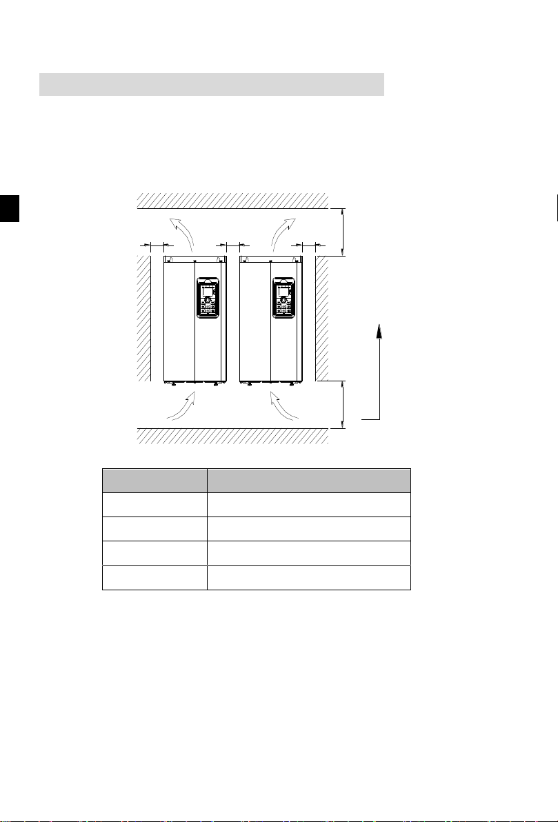
Power rating
Dimension requirement
0.75~11kW
A≥100mm;B≥10mm
15~22kW
A≥200mm;B≥10mm
30~75kW
A≥200mm;B≥50mm
93~400kW
A≥300mm;B≥50mm
Chapter 4 Installation and commissioning
4-1.Installation direction and space
PI500 series inverter according to different power rating, the requirements of around
installation reserve space is different, specifically as shown below:
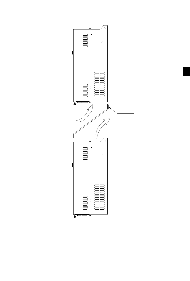
PI500 Series frequency inverter heat radiator circulated from bottom to top, when more than
one inverter work together, usually mounted side by side. In the case of the need to install them by
upper and lower rows, due to the heat of the lower inverters rising to the upper equipment, fault
maybe caused, heat insulation deflector and other objects to be installed.
Figure 4-1:PI500 Series Each power level installation space requirement
16
Chapter 4 Installation and commissioning
Chapter 4
Deflector
Cool wind
Hot wind
Figure 4-2:Heat insulation deflector up and down installation diagram
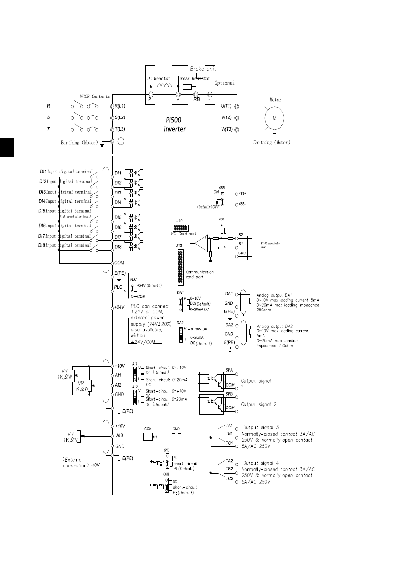
4-2.Wiring Diagram
Frequency inverter wiring is divided by main circuit and control circuit. Users must properly
connect frequency inverter in accordance with the wiring connection diagram showing below.
17
Chapter 4 Installation and commissioning
Chapter 4
Main circuit
Control circuit
4-2-1.Wiring diagram
Figure 4-3:Wiring diagram
18
Chapter 4 Installation and commissioning
Chapter 4
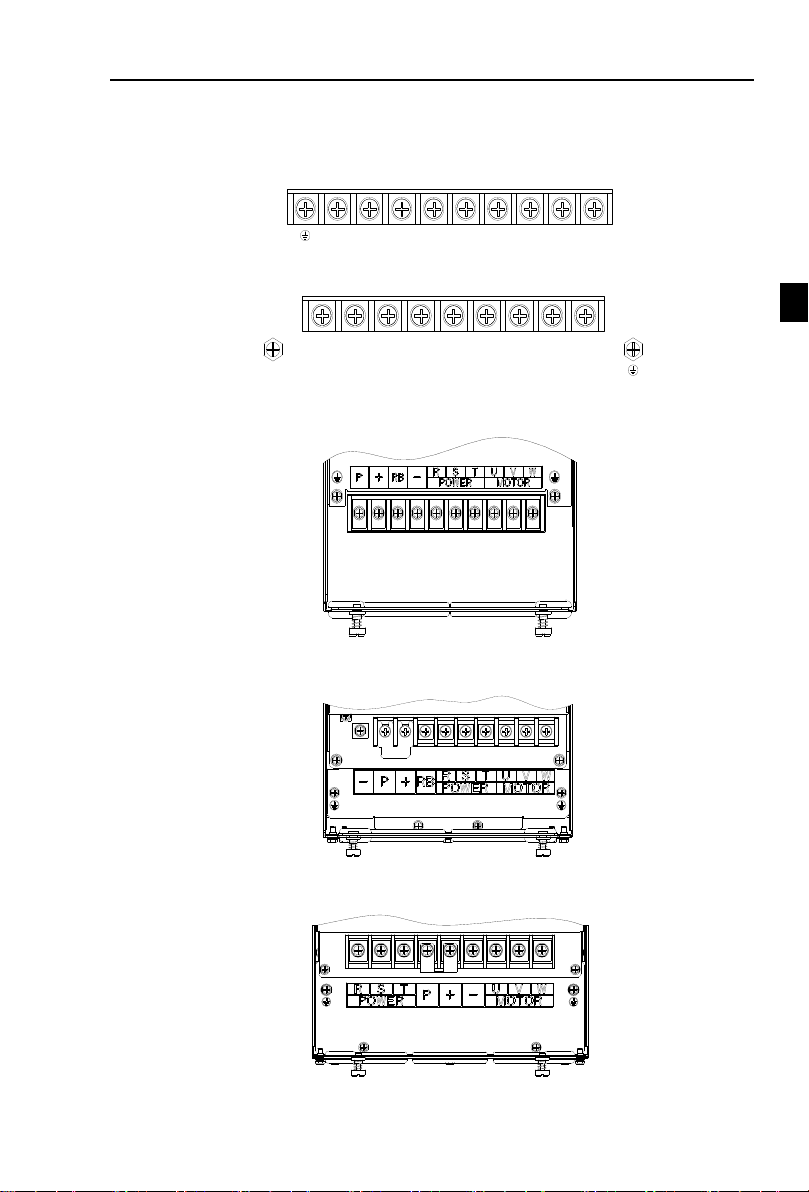
R S T + RB - U V W
R S T+RB
-
U V WP
4-3.Main circuit terminal
4-3-1.Main circuit terminal arrangement
1.0.75~4kW G3 main circuit terminal
Figure 4-4:0.75~4kW G3 main circuit terminal
2.5.5~11kW G3 main circuit terminal
Figure 4-5:5.5~11kW G3 main circuit terminal
3.15kW G3 main circuit terminal
Figure 4-6:11~15kW G3 main circuit terminal
4.18.5~22kW G3 main circuit terminal
5.30~37kW G3 main circuit terminal
Figure 4-7:18.5~22kW G3 main circuit terminal
Figure 4-8:30~37kW G3 main circuit terminal
19
Chapter 4 Installation and commissioning
Chapter 4
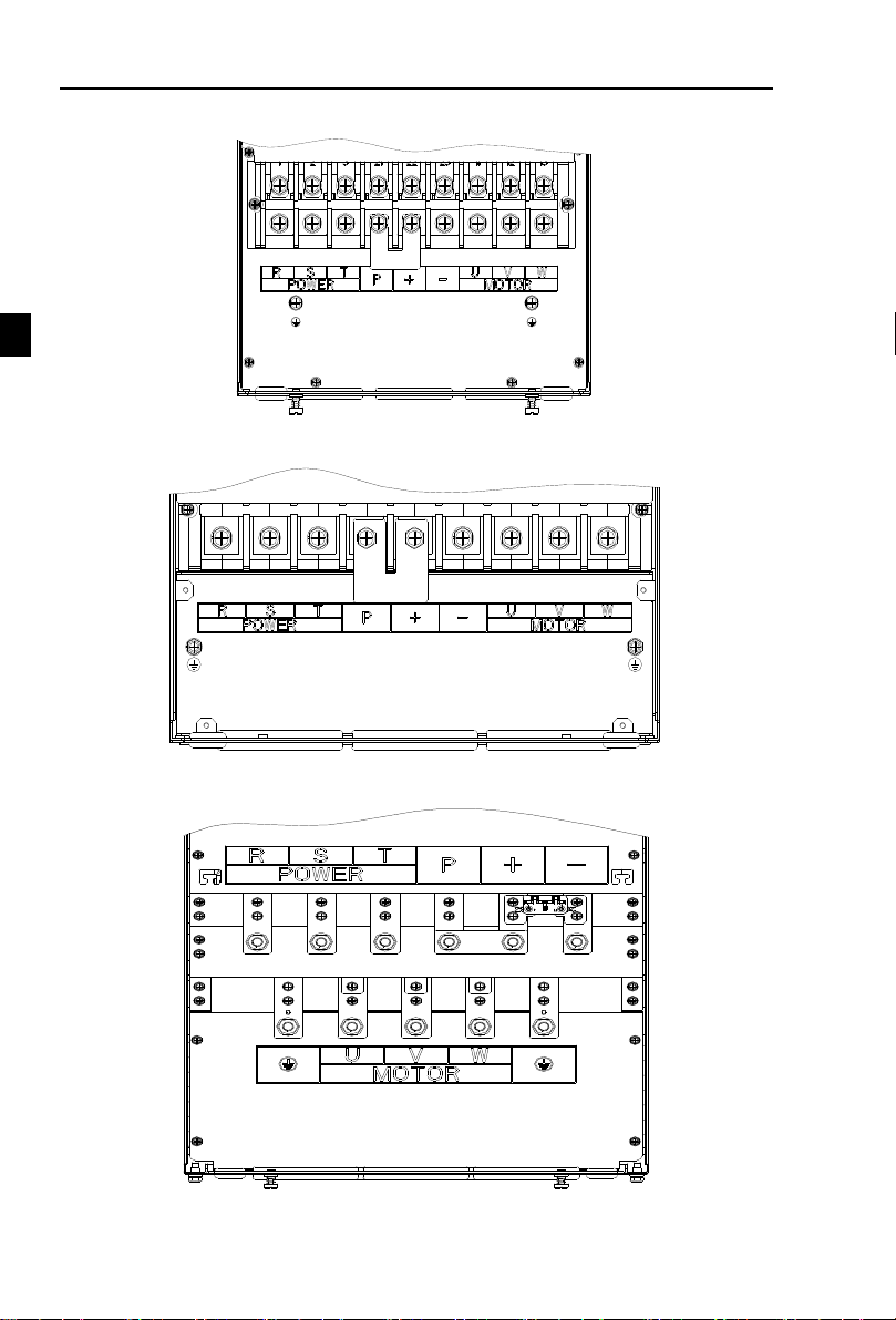
132G3/160F3
6.45~75kW G3 main circuit terminal
Figure 4-9:45~75kW G3 main circuit terminal
7.93~110kW G3 main circuit terminal
8.132kW main circuit terminal
Figure 4-10:93~110kW G3
Figure 4-11:132kW G3 main circuit terminal
20
Chapter 4
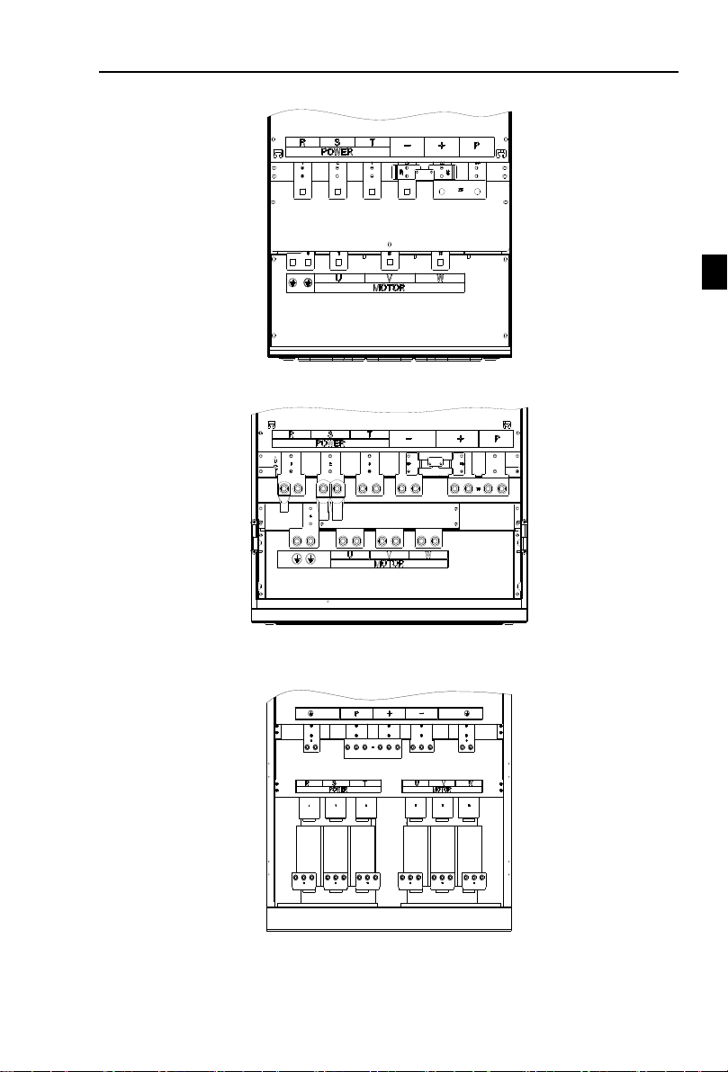
9.160~220kW G3 main circuit terminal
Chapter 4 Installation and commissioning
Figure 4-12:160~220kW G3 main circuit terminal
10.250~400kW G3 main circuit terminal
Figure 4-13:250~400kW G3 main circuit terminal
11.450~630kW G3 main circuit terminal
Note: P/+ standard is circuit standard configuration is for the shorted state; if external DC reactor
is connected, firstly disconnect and then reconnect.
Figure 4-14:450~630kW G3 main circuit terminal
21
Chapter 4 Installation and commissioning
Chapter 4
Terminal
Name
Explain
R
Inverter input terminals
Connect to three-phase power supply, single-phase
connects to R, T
S
T
Ground terminals
Connect to ground
P, RB
Braking resistor terminals
Connect to braking resistor
U
Output terminals
Connect to three-phase motor(Please do not connect single
phase motor)
V
W
+, -
DC bus output terminals
Connect to braking unit
P, +
DC reactor terminals
Connect to DC reactor(remove the shorting block)
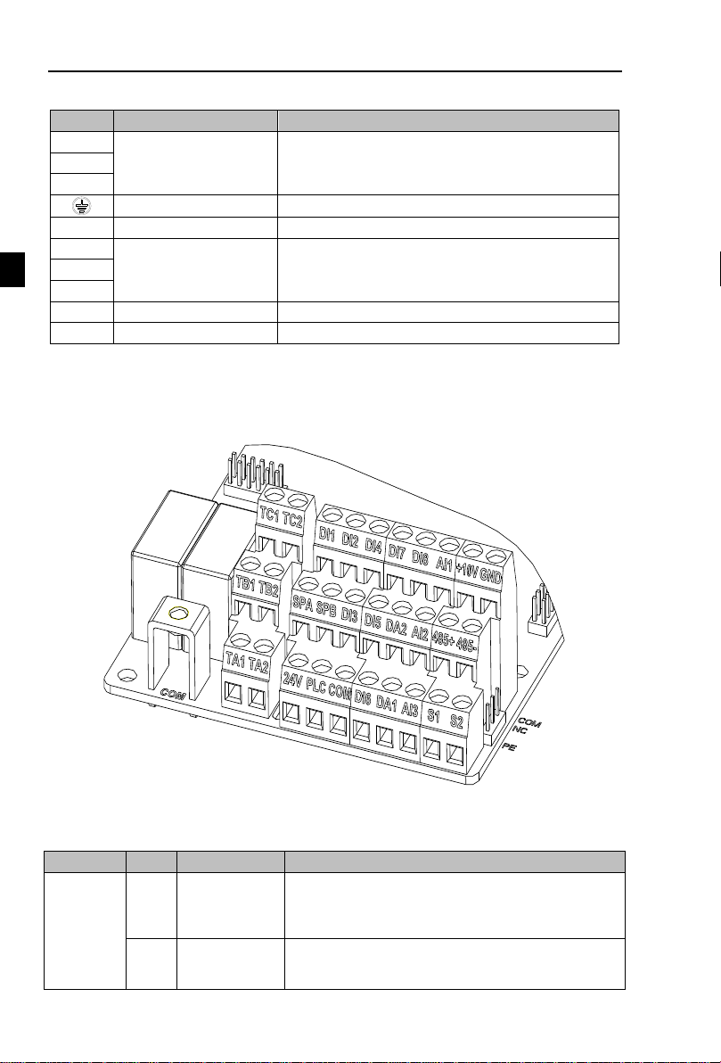
Category
Symbol
Name
Function
Power
supply
+10VGND
+10V power
supply
Output +10V power supply, maximum output current:
10mA
Generally it is used as power supply of external
potentiometer, potentiometer resistance range: 1 to 5kΩ
+24VCOM
+24V power
supply
Output +24V power supply, generally it is used as power
supply of digital input and output terminals and external
sensor.
4-3-2.Function description of main circuit terminal
4-4.Control circuit terminals
4-4-1.Control circuit terminals arrangement
1. Control panel control circuit terminals
Figure 4-15:Control panel control circuit terminals
4-4-2.Description of control circuit terminals
22

Chapter 4 Installation and commissioning
Chapter 4
Category
Symbol
Name
Function
Maximum output current: 200mA
PLC
External power
input terminal
The use of external signal when driving, PLC to be
connected with an external power supply, please unplug
the PLC jumper. Factory default and +24V connection..
Analog
input
AI1GND
Analog input
terminal 1
1.Input range:(DC 0 to 10V/0 to 20mA), depends on the
selected AI1 jumper on control panel.
2.Input impedance: 20kΩ with voltage input,
500
Ω with
current input.
AI2GND
Analog input
terminal 2
1.Input range:(DC 0 to 10V/0to 20mA), depends on the
selected AI2 jumper on control panel.
2.Input impedance: 20kΩ with voltage input,
500
Ω with
current input.
AI3
Analog input
terminal 3
1, Input range:DC-10~+10V
2, Voltage input impedance:20kΩ;
3.AI3 reference potential can be GND or -10V.
Digital
input
DI1
Multi-function
digital input 1
1.Optocoupler, compatible bipolar input, determined by
the choice of the jumper PLC;
2.Input impedance: 3.3kΩ
3.Level input voltage range is 19.2~28.8V.
Note: DI5 input impedance is 1.65k.
DI2
Multi-function
digital input 2
DI3
Multi-function
digital input 3
DI4
Multi-function
digital input 4
DI5
Multi-function
digital input 5
DI6
Multi-function
digital input 6
DI7
Multi-function
digital input 7
DI8
Multi-function
digital input 8
DI5
High-speed
pulse input
terminals
Except the function of DI1 to DI4,DI6 to DI8,DI5 can
also be used as high-speed pulse input channels.
Maximum input frequency: 100kHz
Analog
output
DA1GND
Analog output 1
The selected DA1 jumper on control panel determines
voltage or current output. Output voltage range: 0 to
10V , output current range: 0 to 20mA
DA2GND
Analog output 2
The selected DA2 jumper on control panel determines
voltage or current output. Output voltage range: 0 to
10V , output current range: 0 to 20mA
Digital
output
SPACOM
Digital output 1
Opto-coupler isolation, bipolar open collector output
Output voltage range: 0 to 24V , output current range: 0
to 50mA
SPBCOM
Digital output 2
SPBCOM
High-speed
pulse output
Subject to function code(F2.00)"SPB terminal output
mode selection"
As a high-speed pulse output, the highest frequency up to
100kHz;
Relay
output
TA1TC1
Normally open
terminals
Contactor drive capacity: normally closed contact 3A/AC
250V,normally open contact 5 A/AC 250V, COSø = 0.4.
TB1TC1
Normally closed
terminals
23
Chapter 4 Installation and commissioning
Chapter 4
Category
Symbol
Name
Function
Motor
temperature
inspection
input
S1S2GND
PT100 inspect
wire input
PT100 temperature senso. Note: such as PT100 three
detection line, with a universal table test, to find two of
the detection line is 0Ω after the one received S2
terminal, the other received a GND; the remaining one
received S1 terminal.
Built-in
RS485
485+
485 differential
signal +
terminal
485 communication interface, 485 differential signal
terminal, use twisted-pair or shielded wire connect to the
standard 485 communication interface
485 jump line in the control panel to decide whether to
connect the terminal resistance
485-
485 differential
signal - terminal
Auxiliary
interface
J13
communication
interface
CAN card, 26-pin terminal
J10
PG card interface
12-pin terminal
GND
GND ground
interface
GND jump line decide whether to connect PE, improve
the inverter anti-interference
COM
COM ground
interface
COM jump line decide whether to connect PE, improve
the inverter anti-interference
H1
COM Terminal
interface
Consistent with the COM function on the terminal line。
+24V
COM
PLC
(Default)
DI1
DI8
COM
PLC
PE
Shielded
cable
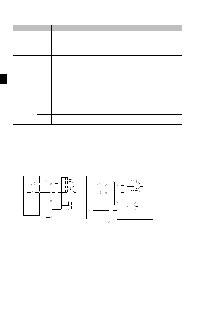
External
contactor
Inverter
Inner power supply with main connect
+24V
COM
PLC
(Default)
DI1
DI8
COM
PLC
PE
Shielded
cable
External
contactor
Inverter
External power supply with main connection
External power
supply
+
-
Signal input terminal circuit
Switch input and output signal transmission, generally use the shielded cable and wiring short
distance as far as possible, good grounding and shielding layer on the inverter side, try not to over 20
m transmission distance. Drive in active way, elected to the power of crosstalk necessary filtering
measures are taken, generally recommend that choose dry contact control mode.
Wiring control cable should be kept with the main circuit and high voltage lines (such as the
power cord, motor connecting line, relay or contactor) more than 20 cm distance, and to avoid high
voltage lines parallel to and can't be avoided and the high voltage lines cross, the proposal USES
vertical wiring way, in order to prevent the misoperation caused by disturbance frequency converter
Dry contact mode:
Note: using an external power supply, PLC and 24 v jumper cap must be removed, otherwise it
Figure 4-16:Signal input terminal circuit- dry contact mode
will damage the product.
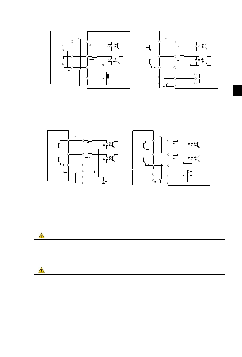
Open collector NPN connect wire:
When the input signal from the NPN transistor, according to the use of power supply, please
according to the figure + 24 v and PLC jumper cap.
24
Chapter 4 Installation and commissioning
Chapter 4
+24V
COM
PLC
(Default)
DI1
DI8
COM
PLC
PE
Shielded
cable
Inverter
Inner power NPN connect mode
External
contactor
+24V
COM
PLC
(Default)
DI1
DI8
COM
PLC
PE
Shielded
cable
Inverter
External power supply NPN connect mode
External
contactor
External
power supply
+
-
+24V
COM
PLC
(Default)
DI1
DI8
COM
PLC
PE
Inverter
Inner power PNP connect mode
External
contactor
+24V
COM
PLC
(Default)
DI1
DI8
COM
PLC
PE
Shielded
cable
Inverter
External power supply PNP
connect mode
External
contactor
External
power supply
+
-
+24V
Danger
Make sure that the power switch is in the OFF state before wiring operation, or electrical shock
may occur!
Wiring must be performed by a professional trained personnel, or this may cause damage to the
equipment and personal injury!
Must be grounded firmly, otherwise there is a danger of electric shock or fire hazard !
Note
Make sure that the input power is consistent with the rated value of inverter, otherwise which
may cause damage to the inverter!
Make sure that the motor matches the inverter, otherwise which may cause damage to the
motor or activate the inverter protection!
Do not connect power supply to U, V, W terminals, otherwise which may cause damage to the
inverter!
Do not directly connect braking resistor to DC bus (P), (+) terminals, otherwise which may
cause a fire!
Figure 4-17:Signal input terminal wiring diagram, open collector NPN connection mode
Note: using an external power supply, PLC and 24 v jumper cap must be removed, otherwise
it will damage the product.
Open collector PNP connection mode:
Figure 4-18:Signal input terminal wiring diagram, open collector PNP connection mode
Note: using an external power supply, PLC and 24 v jumper cap must be removed, otherwise
it will damage the product.
4-5.Wiring Precautions
※ The U,V,W output end of inverter can not install phase advancing capacitor or RC absorbing
device. The inverter input power must be cut off when replacing the motor
25

Chapter 4 Installation and commissioning
Chapter 4
PI500
inverter
M
3
~
R
S
T
U
V
W
K1
K2
K3
MCC1
MCC2
MCC1 & MCC2 interlock ac contactor
※ Do not let metal chips or wire ends into inside the inverter when wiring, otherwise which may
cause malfunction to the inverter.
※ Disconnect motor or switch power-frequency power supply only when the inverter stops
output
※ In order to minimize the effects of electromagnetic interference, it is recommended that a
surge absorption device shall be installed additionally when electromagnetic contactor and
relay is closer from the inverter.
※ External control lines of inverter shall adopt isolation device or shielded wire.
※ In addition to shielding, the wiring of input command signal should also be aligned
separately, it is best to stay away from the main circuit wiring.
※ If the carrier frequency is less than 3KHz, the maximum distance between the inverter and
the motor should be within 50 meters; if the carrier frequency is greater than 4KHz, the
distance should be reduced appropriately, it is best to lay the wiring inside metal tube.
※ When the inverter is additionally equipped with peripherals (filter, reactor, etc.), firstly
measure its insulation resistance to ground by using 1000 volt megger, so as to ensure the
measured value is no less than 4 megohms.
※ When the inverter need to be started frequently, do not directly turn power off, only the
control terminal or keyboard or RS485 operation command can be used to control the
start/stop operation, in order to avoid damage to the rectifier bridge.
※ To prevent the occurrence of an accident, the ground terminal( )must be earthed
firmly(grounding impedance should be less than 10 ohms), otherwise the leakage current
will occur.
※ The specifications on wires used by the main circuit wiring shall comply with the relevant
provisions of the National Electrical Code.
※ The motor's capacity should be equal to or less than the inverter's capacity.
4-6.Spare Circuit
When the inverter occurs the fault or trip, which will cause a larger loss of downtime or other
unexpected faults. In order to avoid this case from happening, please additionally install spare circuit
to ensure safety.
Note: Electrical diagram MCC1 and MCC2 interlock ac contactor; Spare circuit must be
confirmed in advance and test running characteristics, make sure that the power frequency and
frequency conversion phase sequence
4-7.Commissioning
26
Figure 4-19:Spare Circuit electrical diagram

Chapter 4
F0.00=?
Correctly set motor and
encoder parameters
Vector control W/PG
V/F
1
2
Select command source
Select suitable frequency
source
Start motor to run,observe the
phenomenon,if abnormal,please
refer to the troubleshooting
End
Select motor start-up mode
Control
NO
YES
Achieve the required
control effect?
0
Vector control W/O PG
Select motor stop mode
Correctly motor parameters
Motor parameter self-learning
Commission ing
Select control manner
(setting F0.00)
(Set b0.00-b0.05,b0.28,etc)
(Set b0.00-b0.05)
Select appropriate
ac/deceleration time
(Set F0.13,F0.14)
Select appropriate
ac/deceleration time
(Set F0.13,F0.14)
(Set b0.27)
Motor parameter self-learning
(Set b0.27)
(Set F0.11)
(Set F0.03,F0.04,F0.07,etc)
(Set F3.00)
Select appropriate
ac/deceleration time
(Set F0.13,F0.14)
(Set F3.07)
Chapter 4 Installation and commissioning
● Firstly confirm that AC input power supply voltage shall be within inverter rated input
● Connect power supply to the R, S and T terminals of the inverter.
● Select the appropriate operation control method.
voltage range before connecting power supply to the inverter.
Figure 4-20:Commissioning
27

第
十
Chapter 5
Code
Parameter name
Functional Description
d0
Monitoring function group
Monitoring frequency, current, etc
F0
Basic function group
Frequency setting, control mode, acceleration and
deceleration time
F1
Input terminals group
Analog and digital input functions
F2
Output terminals group
Analog and digital output functions
F3
Start and stop control group
Start and stop control parameters
F4
V/F control parameters
V/F control parameters
F5
Vector control parameters
Vector control parameters
F6
Keyboard and display
To set key and display function parameters
F7
Auxiliary function group
To set Jog, jump frequency and other auxiliary function
parameters
F8
Fault and protection
To set fault and protection parameters
F9
Communication parameter group
To set MODBUS communication function
FA
Torque control parameters
To set parameters under torque control mode
Fb
Control optimization parameters
To set parameters of optimizing the control performance
FC
Extend parameters group
specialapplicationparameterssetting
E0
Wobbulate, fixed-length and
counting
To set Wobbulate, fixed-length and counting function
parameters
E1
Multi-stage command, simple PLC
Multi-speed setting, PLC operation
E2
PID function group
To set Built-in PID parameters
E3
Virtual DI, Virtual DO
Virtual I/O parameter setting
b0
Motor parameters
To set motor parameter
y0
Function code management
To set password, parameter initialization and parameter
group display
Chapter 5 Function parameter
5-1.Menu grouping
Note:
“★”: In running status, can not modify the parameter setting
“●”: The actual testing data, can not be modified
“☆”: In stop and run statuses, both can be changed;
“▲”: “Factory parameter”, no change about it.
“_” means the factory parameter is related to power or model. Please check the details in the
involved parameter introduction.
Note:“Italic ³”means software version is C3.00 and the keyboard just like the above with
MCU can do the functions.
Change limit refers to whether the parameters are adjustable.
y0.01 is used for parameters protection password. Parameter menu can be enter into only after
inputting the right password in the function parameter mode or user change parameter mode. When
the y0.01 set to 0, the password is canceled.
Parameter menu is not protected by password under user customized parameters mode.
F group is the basic function parameters,E group is to enhance function parameters, b group is
a function of motor parameters,d group is the monitoring function parameters.
28

Chapter 5
y1
Fault query
Fault message query
5-1-1.d0Group - Monitoring function group
No.
Code
Parameter name
Setting range
Factory
setting
1
d0.00
Running frequency
Frequency converter theory
0.01Hz
2
d0.01
Set frequency
Actual set frequency
0.01Hz
3
d0.02
DC bus voltage
Detected value for DC bus voltage
0.1V
4
d0.03
output voltage
Actual output voltage
1V
5
d0.04
output current
Effective value for Actual motor current
0.01A
6
d0.05
output power
Calculated value for motor output power
0.1kW
7
d0.06
output torque
Motor output torque percentage
0.1%
8
d0.07
DI input status
DI input status
- 9 d0.08
DO output status
DO output status
-
10
d0.09
AI1 voltage (V)
AI1 input voltage value
0.01V
11
d0.10
AI2 voltage (V)
AI2 input voltage value
0.01V
12
d0.11
AI3 voltage (V)
AI3 input voltage value
0.01V
13
d0.12
Count value
Actual pulse count value in counting function
-
14
d0.13
Length value
Actual length in fixed length function
-
15
d0.14
Actual operating speed
Motor actual running speed
-
16
d0.15
PID setting
Reference value percentage when PID runs
%
17
d0.16
PID feedback
Feedback value percentage when PID runs
%
18
d0.17
PLC stage
Stage display when PLC runs
-
19
d0.18
High-speed pulse input
frequency
High-speed pulse input frequency display,
unit: 0.01Khz
0.01kHz
20
d0.19
Feedback
speed(unit:0.1Hz)
Actual output frequency of converter
0.01Hz
21
d0.20
Remaining run time
Remaining run time display, it is for timing
run control
0.1Min
22
d0.21
Linear speed
Show the line speed of DI5 high speed pulse
sampling, according to the actual sample
pulse number per minute and E0.07, calculate
the line speed value.
1m/Min
23
d0.22
Current power-on time
Total time of current inverter power-on
Min 24
d0.23
Current run time
Total time of current inverter run
0.1Min
25
d0.24
HDI(DI5) impulse
frequency
HDI(DI5) High-speed impulse input
frequency display, unit: 1Hz
1Hz 26
d0.25
Communication set value
Frequency, torque or other command values
set by communication port
0.01%
27
d0.26
Encoder feedback speed
PG feedback speed, to an accuracy of 0.01Hz
0.01Hz
28
d0.27
Master frequency display
Frequency set by F0.03 master frequency
setting source
0.01Hz
Chapter 5 Function parameter
29

Chapter 5 Function parameter
Chapter 5
29
d0.28
Auxiliary frequency
display
Frequency set by F0.04 auxiliary frequency
setting source
0.01Hz
30
d0.29
Command torque (%)
Observe the set command torque under the
torque control mode
0.1%
31
d0.30
Reserve
32
d0.31
Synchro rotor position
Synchro rotor position angle
0.0°
33
d0.32
Resolver position
Rotor position when rotary transformer is
used as a speed feedback
-
34
d0.33
ABZ position
Position information calculated from when
ABZ incremental feedback encoder is
adopted
0
35
d0.34
Z signal counter
Encoder Z-phase signal count
-
36
d0.35
Inverter status
Display run, standby and other statuses
-
37
d0.36
Inverter type
1.G type (constant torque load type)
2.F type (fans/pumps load type)
-
38
d0.37
AI1 voltage before
correction
Input voltage value before AI1 linear
correction
0.01V
39
d0.38
AI2 voltage before
correction
Input voltage value before AI2 linear
correction
0.01V
40
d0.39
AI3 voltage before
correction
Input voltage value before AI3 linear
correction
0.01V
41
d0.40
Reserve
42
d0.41
motor temperature
inspection function3
PT100 inspect motor temperature value
0℃
No.
Code
Parameter name
Setting range
Factory
setting
Chan-
ge
43
F0.00
Motor control manner
0.Vector control W/O PG
1.Vector control W/ PG
2.V/F control
2
★
44
F0.01
Keyboard set frequency
0.00Hz to F0.19 (maximum frequency)
50.00Hz
☆
45
F0.02
Frequency command
resolution
1: 0.1Hz; 2: 0.01Hz
2
★
46
F0.03
Frequency source master
setting
0: frequency setting by keyboard
(F0.01, UP/DOWN can be modified, no
memory when power off )
1. frequency setting by keyboard
(F0.01, UP/DOWN can be modified,
memory when power off )
2: analogquantity AI1 setting
3: analogquantity AI2 setting
4: panel potentiometer setting
5: high speed pulse setting
6: multi-speed running setting
7: simple PLC program setting
8: PID control setting
9: remote communication setting
1
★
5-1-2.F0 Group -Basic function group
30

Chapter 5 Function parameter
Chapter 5
10: analog quantity AI3 setting
47
F0.04
Frequency source
auxiliary setting
The same as F0.03
0
★
48
F0.05
Reference object
selection for frequency
source auxiliary setting
0. relative to maximum frequency
1.relative to master frequency source 1
2. relative to master frequency source 2
0
☆
49
F0.06
Frequency source
auxiliary setting range
0% to 150%
100%
☆
50
F0.07
Frequency source
superimposed selection
Units digit: frequency source selection
Tens digit: arithmetic relationship of
master and auxiliary for frequency
source
00
☆
51
F0.08
Fr
equency source offset
frequency when
superimposing
0.00Hz to F0.19(maximum frequency)
0.00Hz
☆
52
F0.09
Shutdown memory
selection for digital set
frequency
0: W/O memory
1: With memory
1 ☆ 53
F0.10
Frequency command UP
/ DOWN reference when
running
0: Running frequency
1: Set frequency
0
★
54
F0.11
Command source
selection
0.Keyboard control (LED off)
1.Terminal block control (LED on)
2.Communications command control
(LED flashes)
3. Keyboard control+ Communications
command control
4. Keyboard control+ Communications
command control+ Terminal block
control
0
☆
55
F0.12
Binding frequency
source for command
source
Units digit: binding frequency source
selection for operation panel command
0: no binding;
1. Keyboard setting frequency;
2: analog quantity AI1 setting
3: analog quantity AI2 setting
4: panel encoder setting
5: high speed pulse setting
6: multi-speed setting
7: simple PLC setting
8: PID setting
9: communication given
Tens digit: terminal command binding
frequency source selection (0 to 9, same
as units digit)
Hundreds digit: communication
command binding frequency source
selection (0 to 9, same as units digit)
000
☆
56
F0.13
Acceleration time 1
0.00s to 6500s
Depends
on models
☆
31

Chapter 5 Function parameter
Chapter 5
57
F0.14
Deceleration time 1
0.00s to 6500s
Depends
on models
☆
58
F0.15
Ac/Deceleration time
unit
0:1 second;1:0.1 second;
2:0.01 second
1
★
59
F0.16
Ac/deceleration time
reference frequency
0: F0.19(maximum frequency)
1: Set frequency
2: 100Hz
0 ★ 60
F0.17
Carrier frequency
adjustment as per
temperature
0:
NO; 1:
YES
0
☆
61
F0.18
Carrier Frequency
0.5kHz to 16.0kHz
Depends
on
models
☆
62
F0.19
Maximum output
frequency
50.00Hz to 320.00Hz
50.00Hz
★
63
F0.20
Upper limit frequency
source
0: F0.21 setting
1: AI1analog quantity setting
2: AI2 analog quantity setting
3: Panel encoder setting
4: High-speed pulse setting
5: communications reference
6:AI3 analog quantity setting
0
★
64
F0.21
Upper limit frequency
F0.23 (lower limit frequency) to
F0.19(maximum frequency)
50.00Hz
☆
65
F0.22
Upper limit frequency
offset
0.00Hz to F0.19 (maximum frequency)
0.00Hz
☆
66
F0.23
Lower limit frequency
0.00Hz to F0.21 (upper limit frequency)
0.00Hz
☆
67
F0.24
Running direction
0:
same direction; 1: opposite direction
0
☆
68
F0.25
Reserve
69
F0.26
AI Simulation accuracy
0: 0.01Hz; 1: 0.05Hz;
2: 0.1Hz; 3: 0.5Hz
1
☆
70
F0.27
GF type
1.G type (constant torque load type)
2.F type (fans/pumps load type)
-
●
No.
Code
Parameter name
Setting range
Factory
setting
Chan-
ge
71
F1.00
DI1 terminal function selection
0 to 51
1 ★ 72
F1.01
DI2 terminal function selection
2 ★ 73
F1.02
DI3 terminal function selection
8 ★ 74
F1.03
DI4 terminal function selection
9 ★ 75
F1.04
DI5 terminal function selection
12 ★ 76
F1.05
DI6 terminal function selection
13 ★ 77
F1.06
DI7 terminal function selection
0 ★ 78
F1.07
DI8 terminal function selection
0 ★ 79
F1.08
Undefined
5-1-3.F1 Group - Input terminals group
32

Chapter 5 Function parameter
Chapter 5
80
F1.09
Undefined
The function of digital multifunction input terminal DI1-DI8 (DI5 can be used as a high-speed
pulse input terminal), can be set by parameter F1.00-F1.07, and the optional function is shown in
the following table:
Set
value
Function
Description
0
No function
The terminal for not use can be set to "no function" to
prevent accidental operation.
1
Forward run (FWD)
External terminals are used to control the FWD/REV run
mode of inverter.
2
Reverse run (REV)
3
Three-wire operation
control
This terminal is used to determine the inverter's three-wire
control mode. For details, please refer to the instructions
of function code F1.10 ("terminal command mode).
4
Forward JOG(FJOG)
FJOG means Forward JOG running, RJOG means
Reverse JOG running. For Jog running frequency and Jog
Ac/deceleration time, please refer to the description of the
function code F7.00, F7.01, F7.02.
5
Reverse JOG(RJOG)
6
Terminal UP
Modify frequency increment/decrement command when
the frequency is referenced by external terminal. Adjust
up/down the set frequency when the digital setting is
selected as the frequency source.
7
Terminal DOWN
8
Free stop
The inverter output is blocked, at the time, the parking
process of motor is not controlled by the inverter. This
way is same as the principle of free stop described in
F3.07.
9
Fault reset (RESET)
The function make use of terminal for fault reset. It has
same function with RESET key on the keyboard. This
function can be used to realize remote fault reset.
10
Run pausing
The inverter slows down and stops, but all operating
parameters are memorized. Such as PLC parameters,
wobbulate frequency parameters, and PID parameters.
This terminal signal disappears, the inverter reverts to the
previous state of running before parking.
11
External fault normally
open input
When the signal is sent to the inverter, the inverter reports
fault Err.15, and performs troubleshooting according to
fault protection action (for details, please refer to the
function code F8.17).
12
Multi-speed terminal 1
The setting of 16 stage speed or 16 kinds of other
command can be achieved through the 16 states of the
four terminals. For details, see Table 1
13
Multi-speed terminal 2
14
Multi-speed terminal 3
15
Multi-speed terminal 4
16
Ac/deceleration time
selection terminal 1
The selection of 4 ac/deceleration times can be achieved
through the 4 states of the two terminals. For details, see
Table 2
17
Ac/deceleration time
selection terminal 2
18
Frequency source
switching
Used to switch between different frequency sources.
According to frequency source selection function code
(F0.07) settings, the terminal is used to switch between
two frequency sources.
33

Chapter 5 Function parameter
Chapter 5
19
UP/DOWN setting
(terminal, keyboard)
When the frequency reference is the digital frequency, this
terminal is used to clear the changed frequency value by
terminal UP/DOWN or keyboard UP/DOWN, so that the
reference frequency can recover to the set value of F0.01.
20
Run command switch
terminal 1
When the command source is set to the terminal control
(F0.11 = 1), the terminal can be used to switch between
terminal control and keyboard control.
When the command source is set to the communication
control (F0.11 = 2), the terminal can be used to switch
between communication control and keyboard control.
21
Ac/deceleration prohibited
Ensure the inverter is free from external signals affect
(except for shutdown command), maintain current output
frequency.
22
PID pause
PID is temporarily disabled, the inverter maintains current
output frequency, no longer performs PID adjustment of
frequency source.
23
PLC status reset
When PLC pauses and runs again, this terminal is used to
reset the inverter to the initial state of simple PLC.
24
Wobbulate pause
When the inverter outputs at center frequency. Wobbulate
will pause
25
Counter input
Input terminal of the count pulse
26
Counter reset
Clear counter status
27
Length count input
Input terminal of the length count.
28
Length reset
Clear length
29
Torque control prohibited
When the inverter torque control is prohibited, the inverter
will enter speed control mode.
30
High-speed pulse input
(only valid for DI5 )
DI5 is used as pulse input terminal.
31
Reserve
Reserve
32
Immediately DC braking
If the terminal is active, the inverter switches directly to
DC braking status
33
External fault normally
closed input
When the signal of external fault normally closed input is
inputted into the inverter, the inverter will report fault
Err.15 and shutdown.
34
Frequency change enable
If the function is set to be valid, when the frequency
changes, the inverter does not respond to frequency
changes until the terminal state is invalid.
35
PID action direction as
reverse
If the terminal is valid, PID action direction opposites to
the direction set by E2.03
36
External parking terminal
1
Under keyboard control mode, the terminal can be used to
stop the inverter, same as STOP key on the keyboard.
37
Control command switch
terminal 2
Used to switch between terminal control and
communication control. If the command source is selected
as terminal control, the system will be switched to the
communication control mode when the terminal is active;
vice versa.
38
PID integral pause
When the terminal is active, the PID integral adjustment
function is paused, but the proportion and differential
adjustments of PID are still valid.
34

Chapter 5 Function parameter
Chapter 5
39
Switch between frequency
source master setting and
preset frequency
When the terminal is active, the frequency source A is
replaced by the preset frequency (F0.01)
40
Switch between frequency
source auxiliary setting
and preset frequency
When the terminal is active, the frequency source B is
replaced with the preset frequency (F0.01)
41
Reserve
42
Reserve
43
PID parameter switching
When DI terminal (E2.19 = 1) is used to switch PID
parameters, if the terminal is invalid, PID parameters use
E2.13 to E2.15; if the terminal is valid, PID parameters
use E2.16 to E2.18
44
Custom fault 1
When custom fault 1 and custom fault 2 are active, the
inverter respectively alarms fault Err.27 and fault Err.28,
and deals with them according to the mode selected by the
fault protection action F8.19.
45
Custom fault 2
46
Speed control / torque
control switching
Switch between speed control mode and torque control
mode under vector control mode. If the terminal is invalid,
the inverter will run at the mode defined by FA.00
(speed/torque control mode); if the terminal is valid, the
inverter will be switched to another mode.
47
Emergency parking
If the terminal is valid, the inverter will park at the fastest
speed, and the current maintains at the set upper limit
during the parking process. This function is used to meet
the requirements that the inverter needs to stop as soon as
possible when the system is in a emergency state.
48
External parking terminal
2
In any control mode (keyboard control, terminal control,
communication control), the terminal can be used to
decelerate the inverter until stop, at the time the
deceleration time is fixed for deceleration time 4.
49
Deceleration DC braking
If the terminal is valid, firstly the inverter decelerates to
the initial frequency of stop DC braking, and then
switches directly to DC braking status.
50
Clear current running time
If the terminal is valid, the inverter's current running time
is cleared
51
Jog order
Jog running order,direction set through F7.54
81
F1.10
Terminal command mode
0: Two-wire type 1
1: Two-wire type 2
2: Three-wire type 1
3: Three-wire type 2
0
★
82
F1.11
Terminal UP/DOWN change rate
0.001Hz/s to 65.535Hz/s
1.000Hz/s
☆
83
F1.12
Minimum input for AIC1
0.00V to F1.14
0.30V ☆
84
F1.13
F1.12corresponding setting
-100.0% to +100.0%
0.0%
☆
85
F1.14
Maximum input for AIC1
F1.12 to +10.00V
10.00V
☆
86
F1.15
F1.14corresponding setting
-100.0% to +100.0%
100.0%
☆
87
F1.16
Minimum input for AIC2
0.00V to F1.18
0.00V
☆
88
F1.17
F1.16corresponding setting
-100.0% to +100.0%
0.0%
☆
89
F1.18
Maximum input for AIC2
F1.16 to +10.00V
10.00V
☆
90
F1.19
F1.18corresponding setting
-100.0% to +100.0%
100.0%
☆
35

Chapter 5 Function parameter
Chapter 5
91
F1.20
Minimum input for AIC3
-10.00V to F1.22
0.00V
☆
92
F1.21
F1.20corresponding setting
-100.0% to +100.0%
0.0%
☆
93
F1.22
Maximum input for AIC 3
F1.20 to +10.00V
10.00V
☆
94
F1.23
F1.22corresponding setting
-100.0% to +100.0%
100.0%
☆
95
F1.24
AIcurve selection
Units digit: AI1 curve selection
Tens digit: AI2 curve selection
Hundreds digit:panel
potentiometer curve selection
321
☆
96
F1.25
Setting selection for AI input
Units digit: setting selection for
AI1 less than minimum input
0: corresponding to minimum
setting 1: 0.0%
Tens digit: setting selection for
AI2 less than minimum input,
ditto
Hundreds digit: setting selection
for AI3 less than minimum
input(0 to 1,ditto)
000
☆
97
F1.26
HDI Minimum pulse input
0.00kHz to F1.28
0.00kHz
☆
98
F1.27
F1.26 corresponding setting
-100.0% to +100.0%
0.0%
☆
99
F1.28
HDI Maximum input
F1.26 to 100.00kHz
50.00kHz
☆
100
F1.29
F1.28 corresponding setting
-100.0% to +100.0%
100.0%
☆
101
F1.30
DI filter time
0.000s to 1.000s
0.010s
☆
102
F1.31
AI1 filter time
0.00s to 10.00s
0.10s
☆
103
F1.32
AI2 filter time
0.00s to 10.00s
0.10s
☆
104
F1.33
AI3 filter time
0.00s to 10.00s
0.10s
☆
105
F1.34
HDI Filter time
0.00s to 10.00s
0.00s
☆
106
F1.35
DI terminal valid mode
selection 1
Units digit: DI1
0: high level active
1: low level active
Tens digit: DI2
Hundreds digit: DI3
Thousands digit: DI4
Ten thousands digit: DI5
00000
★
107
F1.36
DI terminal valid mode
selection 2
Units digit: DI6
0: high level active
1: low level active
Tens digit: DI7
Hundreds digit: DI8
Thousands digit: DI9
Ten thousands digit: DI10
00000
★
108
F1.37
DI1 delay time
0.0s to 3600.0s
0.0s
★
109
F1.38
DI2 delay time
0.0s to 3600.0s
0.0s
★
110
F1.39
DI3 delay time
0.0s to 3600.0s
0.0s
★
111
F1.40
Define the input terminal repeat
0:unrepeatable 1:repeatable
0
★
36

Chapter 5
112
F1.41
Keyboard Encoder X1
0~100.00%
0.00%
☆
113
F1.42
Keyboard Encoder X2
0~100.00%
0.50%
☆
114
F1.43
Keyboard Encoder set value
0~100.00%
-
☆
115
F1.44
Keyboard Encoder X1
corresponding value Y1
-100.00%~+100.00%
0.00%
☆
116
F1.45
Keyboard Encoder X2
corresponding valueY2
-100.00%~+100.00%
100.00%
☆
117
F1.46
Keyboard Encoder
control
Bits:
0: Power down protection
1: Power down zero clear
Ten bits:
0: Stop keep
1: Stop order zero clear
2: Stop over zero clear
Hundred bits: reserve
Thousand bits: reserve
00
☆
5-1-4.F2 Group - Output terminals group
No.
Code
Parameter name
Setting range
Factory
setting
Chan-
ge
118
F2.00
SPB terminal output mode selection
0 to 1 0 ☆
119
F2.01
Switching quantity output function
selection
0 to 40
0 ☆ 120
F2.02
Relay 1 output function selection
(TA1.TB1.TC1)
2
☆
121
F2.03
Undefined
122
F2.04
SPA output function selection
(collector open circuit output
terminals)
1
☆
123
F2.05
Relay 2 output function selection
(TA2.TB2.TC2)
1
☆
Above 5 function code is used to select five digital output function. Multifunctional output
terminal functions are as follows:
Setting
value
Functions
Description
0
No output
No output action
1
Inverter running
Inverter is in running state, the output frequency (can be
zero), the output ON signal.
2
Fault output (fault
down )
When the drive fails and downtime, the output ON signal.
3
Frequency level
detection FDT1 output
Please refer to the function code F7.23, F7.24's
instructions.
4
Frequency arrival
Please refer to the description of function code F7.25.
5
Zero-speed running (no
output when shutdown)
Inverter operation and the output frequency is 0, output
ON signal. When the drive is shut down, the signal is
OFF.
Chapter 5 Function parameter
37

Chapter 5 Function parameter
Chapter 5
6
Motor overload prealarm
Before the motor overload protection, according to the
overload pre-alarm threshold value judgment, more than
the pre-alarm threshold value output ON signal. Motor
overload parameter settings refer to the function code
F8.02 ~ F8.04.
7
Inverter overload prealarm
Before the inverter overload occurs 10s, output ON
signal.
Setup counter arrive
8
Setup counter arrive
When the count reaches the set value of E0.08, output
ON signal.
Specifies the count value reaches
9
Specifies the count
value reaches
When the count reaches the set value of E0.09, output
ON signal. Counting Function Reference E0 group
10
Length arrival
When the actual length of the detection of more than
E0.05 set length, output ON signal.
11
PLC cycle is complete
After simple PLC completes one cycle, the output of a
pulse width of 250ms signal.
12
Total running time
arrival
Inverter total running time of more than F7.21 F6.07 set
time, the output ON signal.
13
Limited in frequency
When the set frequency exceeds the upper limit
frequency or lower frequency, and output frequency is
beyond the upper limit frequency or lower limit
frequency, output ON signal.
14
Torque limiting
Drive under the speed control mode, when the output
torque reaches the torque limit, the inverter is stall
protection status, while the output ON signal.
15
Ready to run
When the inverter main circuit and control circuit power
supply has stabilized, and the drive does not detect any
fault information, the drive is in an operational state,
output ON signal.
16
AI1>AI2
When the value of the analog input AI is greater than the
value of AI2 input and output ON signal.
17
Upper frequency arrival
When the operating frequency reaches the upper
frequency, output ON signal.
18
The lower frequency
arrival (no output when
shutdown)
When the operating frequency reaches the lower
frequency, output ON signal. The next stop status signal
is OFF.
19
Under voltage state
output
When the inverter is in an undervoltage condition, output
ON signal.
20
Communication setting
Refer to the communication protocol.
21
Reserve
Reserve
22
Reserve
Reserve
23
Zero-speed operation 2
(shutdown also output)
The inverter’s output frequency is 0, output ON signal.
The signal is also ON when shutdown.
24
Cumulative power-on
time arrival
When the inverter's accumulated power on time (F6.08)
over F7.20 the set time, the output ON signal.
25
Frequency level
detection FDT2 output
Please refer to the function code F7.26, F7.27's
instructions.
26
Frequency 1 reaches
output
Please refer to the function code F7.28, F7.29's
instructions.
38

Chapter 5 Function parameter
Chapter 5
27
Frequency 2 reaches
output
Please refer to the function code F7.30, F7.31's
instructions.
28
Current 1 reaches output
Please refer to the function code F7.36, F7.37's
instructions.
29
Current 2 reaches output
Please refer to the function code F7.38, F7.39's
instructions.
30
Timing reach output
When the timer function selection (F7.42) is valid, the
drive time to reach this run after the set time runs out,
output ON signal.
31
AI1 input overrun
When the value of analog input AI1 greater than F7.51
(AI1 input protection limit) or less than F7.50 (AI1 input
protection under), output ON signal.
32
Off load
When the inverter is off-load state, output ON signal.
33
Reverse operation
Inverter in reverse run, output ON signal
34
0 current state
Refer to the description of function code F7.32, F7.33.
35
Module temperature
reaches
Inverter module heatsink temperature (F6.06) reach the
set module temperature reaches value (F7.40), output
signal ON.
36
Software current limit
Please refer to the function code F7.34, F7.35's
instructions.
37
The lower frequency
arrival (stop and output)
When the operating frequency reaches the lower limit
frequency, output ON signal. In shutdown state of the
signal is also ON.
38
Alarm output
When the inverter failure, and the failure of the process to
continue to run mode, the inverter alarm output.
39
Motor overtemperature
pre-warning
When the motor temperature reaches F8.35 (motor
overheat pre-alarm threshold), the output ON signal.
(Motor temperature can be viewed at d0.41)
40
Current running time of
arrival
When the inverter starts running time is longer than the
time set by F7.45, it outputs ON signal.
124
F2.06
High-speed pulse output function
selection
0 to 17
0
☆
125
F2.07
DA1 output function selection
2 ☆ 126
F2.08
DA2 output function selection
13
☆
High-speed pulse output frequency range of 0.01kHz ~ F2.09 (high speed pulse output
maximum frequency), F2.09 can be set between 0.01kHz ~ 100.00kHz.
Analog Output DA1 and DA2 output range is 0V ~ 10V, or 0mA ~ 20mA. Pulse output or
analog output range, with the corresponding scaling function relationship in the following table:
Setting
value
Functions
Description
0
Running frequency
0~Max. output frequency
1
Set frequency
0~ Max. output frequency
2
Output current
0~2 times the motor rated current
3
Output torque
0~2 times the motor rated toqure
4
Output power
0~2 times rated power
5
Output voltage
0~1.2 times inverter rated voltage
6
High speed pulse input
0.01kHz~100.00kHz
39

Chapter 5 Function parameter
Chapter 5
7
Anolog AI1
0V~10V(Or 0~20mA)
8
Anolog AI2
0V~10V(or 0~20mA)
9
Anolog AI3
0V~10V
10
Lentgh value
0~Max. setting length
11
The count value
0~Max. count value
12
Coummunication set
0.0%~100.0%
13
Motor speed
0~Max. output frequency correspondent speed
14
Output current
0.0A~100.0A(Inverter power≦55kW) ;
0.0A~1000.0A(Inverter power>55kW)
15
DC bus voltage
0.0V~1000.0V
16
Reserve
Reserve
17
Frequency source main set
0~Max. output frequency
127
F2.09
Maximum output frequency of highspeed pulse
0.01kHzto 100.00kHz
50.00k
Hz
☆
128
F2.10
SPB switching quantity output delay
time
0.0s to 3600.0s
0.0s
☆
129
F2.11
Relay 1 output delay time
0.0s to 3600.0s
0.0s
☆
130
F2.12
Expansion card DO output delay
time
0.0s to 3600.0s
0.0s
☆
131
F2.13
SPA output delay time
0.0s to 3600.0s
0.0s
☆
132
F2.14
Relay 2 output delay time
0.0s to 3600.0s
0.0s
☆
133
F2.15
DO output terminal active status
selection
Units digit: SPB switching
quantity
0: positive logic
1: anti-logic
Tens digit: Relay 1
Hundreds digit: Hundreds
digit: Undefined
Thousands digit: SPA
Ten thousands digit: Relay 2
00000
☆
134
F2.16
DA1 zero bias coefficient
-100.0% to +100.0%
0.0%
☆
135
F2.17
DA1 gain
-10.00 to +10.00
1.00
☆
136
F2.18
DA2 zero bias coefficient
-100.0% to +100.0%
20.0% ☆
137
F2.19
DA2 gain
-10.00 to +10.00
0.80 ☆
No.
Code
Parameter name
Setting range
Factory
setting
ge
138
F3.00
Start-up mode
0: Direct startup
1: Speed tracking restart
2: Pre-excitation start (AC
asynchronous motor)
0
☆
139
F3.01
Speed tracking mode
0~2: reserve
3: Rotate speed tracking method3
3
★
140
F3.02
Speed tracking value
1 to 100
20
☆
5-1-5.F3 Group - Start and stop control group
40

Chapter 5
141
F3.03
Start frequency
0.00Hz to 10.00Hz
0.00Hz
☆
142
F3.04
Hold time for start frequency
0.0s to 100.0s
0.0s
★
143
F3.05
DC beforehand field current
0% to 100%
0%
★
144
F3.06
DC excitation time beforehand
0.0s to 100.0s
0.0s
★
145
F3.07
Stop mode
0: Deceleration
parking
1: Free
stop
0
☆
146
F3.08
DC Initial frequency
0.00Hz to F0.19 (maximum
frequency)
0.00Hz
☆
147
F3.09
DC Waiting time
0.0s to 100.0s
0.0s
☆
148
F3.10
Stop DC braking current
0% to 100%
0%
☆
149
F3.11
Stop DC braking time
0.0s to 100.0s
0.0s
☆
150
F3.12
Braking utilization rate
0% to 100%
100%
☆
151
F3.13
Ac/deceleration mode
0: Linear acceleration and
deceleration
1:S curve acceleration and
deceleration A
2:S curve acceleration and
deceleration B
0
★
152
F3.14
Proportion of S curve start-section
0.0% to (100.0%to F3.15)
30.0%
★
153
F3.15
Proportion of S curve end-section
0.0% to (100.0% to F3.14)
30.0%
★
5-1-6.F4 Group - V/F control parameters
No.
Code
Parameter name
Setting range
Factory
setting
ge
154
F4.00
V/F curve setting
0: linear V/F,Suitable for
ordinary constant torque load.
1: multi-point V/F,Suitable for
dehydrator, centrifuge and other
special loads any V/F
relationship curves can be
obtained by setting parameters
F4.03 to F4.08.
2: square V/F,Suitable for fans,
pumps and centrifugal loads.
3 to 8: V/F relationship curve
between linear V/F and square
V/F.
0
★
155
F4.01
Torque boost
0.0%(Automatic torque boost)
0.1
to 30%
0.0% ★
156
F4.02
Torque boost cut-off frequency
0.00Hz to F0.19(maximum
frequency)
15.00
Hz
★
157
F4.03
MultipointV/F frequency point 1
0.00Hz to F4.05
0.00Hz
★
158
F4.04
Multipoint V/F voltage point 1
0.0% to 100.0%
0.0%
★
159
F4.05
Multipoint V/F frequency point 2
F4.03 to F4.07
0.00Hz
★
160
F4.06
Multipoint V/F voltage point 2
0.0%
★
Chapter 5 Function parameter
41

Chapter 5 Function parameter
Chapter 5
161
F4.07
Multipoint V/F frequency point 3
F4.05 to b0.04 (rated motor
frequency)
0.00Hz
★
162
F4.08
Multipoint V/F voltage point 3
0.0% to 100.0%
0.0%
★
163
F4.09
Slip compensation coefficient
0% to 200.0%
0.0%
☆
164
F4.10
Overexcitation gain
0 to 200 80 ☆ 165
F4.11
Oscillation suppression gain
0 to 100 0 ☆ 166
F4.12
V/F separation voltage source
0 to 9 0 ☆
167
F4.13
V/F separation
voltage
digital setting
0V to rated motor voltage
0V ☆ 168
F4.14
V/F separation voltage rise time
0.0s to 1000.0s
0.0s
☆
No.
Code
Parameter name
Setting range
Factory
setting
ge
169
F5.00
Speed loop ratio G1
1 to 100
30 ☆ 170
F5.01
Speed loopintegral T1
0.01s to 10.00s
0.50s
☆
171
F5.02
switching frequency 1
0.00 to F5.05
5.00Hz
☆
172
F5.03
Speed loop ratio G2
0 to 100
20 ☆ 173
F5.04
Speed loop integral T2
0.01s to 10.00s
1.00s
☆
174
F5.05
switching frequency 2
F5.02 to F0.19(max. frequency)
10.00Hz
☆
175
F5.06
Speed loop integral
0: invalid 1: valid
0
☆
176
F5.07
Torque limit upper limit source
0: Function code F5.08 setting
1: AI1
2: AI2
3: Panel potentiometer setting
4: High-speed pulse setting
5: Communication setting
6: Min(AI1, AI2)
7: Max(AI1, AI2)
8: AI3 setting
0
☆
177
F5.08
Upper limit digital setting for torque
0.0% to 200.0%
150.0%
☆
178
F5.09
Vector control differential gain
50% to 200%
150%
☆
179
F5.10
Speed loop filter time constant
0.000s to 0.100s
0.000s
☆
180
F5.11
Vector control overexcitation gain
0 to 200 64
☆
181
F5.12
Excitation regulator proportional
gain
0 to 60000
2000
☆
182
F5.13
Excitation regulator integral gain
0 to 60000
1300
☆
183
F5.14
Torque regulator proportional gain
0 to 60000
2000
☆
184
F5.15
Torque regulator integral gain
0 to 60000
1300
☆
No.
Code
Parameter name
Setting range
Factory
setting
ge
185
F6.00
STOP/RESET key functions
0: STOP/RES key is enabled only
1
☆
5-1-7.F5 Group - Vector control parameters
5-1-8.F6 Group - Keyboard and display
42

Chapter 5 Function parameter
Chapter 5
under keyboard operation mode
1:STOP/RES key is enabled under
any operation mode
186
F6.01
Running status display
parameters 1
0x0000 to 0xFFFF
001F
☆
187
F6.02
Running status display
parameters 2
0x0000 to 0xFFFF
0000
☆
188
F6.03
Stop status
display
parameters
0x0000 to 0xFFFF
0033
☆
189
F6.04
Load speed display coefficient
0.0001 to 6.5000
3.0000
☆
190
F6.05
Decimal places for load speed
display
0:0 decimal places
2:2 decimal places
1:1 decimal places
3:3 decimal places
1
☆
191
F6.06
Inverter module radiator
temperature
0.0℃ to 100.0℃
-
●
192
F6.07
Total run time
0h to 65535h
-
●
193
F6.08
Total power-on time
0h to 65535h
- ● 194
F6.09
Total power consumption
0 to 65535 kwh
- ● 195
F6.10
Product series number
Frequency inverter series number
-
●
196
F6.11
Software version number
Control board software version
-
●
197
F6.13
Communication read-write data
selection
Bit: CRC error response selection
0:CRC error response selection;
1:CRC error response selection
Ten: broadcast message screening
option
0: no shielding; 1: shielding.
100 bits: frequency converter fault
information read selection
0: read; 1: not read.
011
☆
198
F6.16
Monitor selection 2
1Kbit/100bit
10bit/1bit
d0.04
☆
parameter
number
parameter series
number
199
F6.17
Power
correction
coefficient
0.00~10.00
1.00
☆
200
F6.18
Multifunction key definition 1
0: UP key is defined as add
function key
1: UP key is defined free stop
2: UP key is defined Forward
running
3: UP key is defined Reverse
running
4: UP key is defined Forward Jog
running
5: UP key is defined Reverse Jog
running
6: UP key is defined UP function
key
7: UP key is defined DOWN
function key
0
☆
43

Chapter 5 Function parameter
Chapter 5
201
F6.19
Multifunction
key
definition 2
The same as F6.18
0
☆
202
F6.20
Keypad lock selection
0:RUN, STOP button valid
1:RUN, STOP, keypad encode valid
2: RUN, STOP, UP, DOWN button
valid
3: STOP button valid
0
☆
203
F6.21
QUICK key function
selection
0: no function; 1: Jog running
2: Shift switch display state
3: FWD/RVS switchover
4: Clear-up UP/DOWN setting
5: Free stop
6: running command given in
sequence
1
☆
No.
Code
Parameter name
Setting range
Factory
setting
ge
204
F7.00
Jog running frequency
0.00Hz to F0.19(maximum
frequency)
2.00Hz
☆
205
F7.01
Jog acceleration time
0.0s to 6500.0s
20.0s
☆
206
F7.02
Jog deceleration time
0.0s to 6500.0s
20.0s
☆
207
F7.03
Jog priority
0:Invalid 1: Valid
1 ☆
208
F7.04
Jump frequency 1
0.00Hz to F0.19 (maximum
frequency)
0.00Hz
☆
209
F7.05
Jump frequency 2
0.00Hz to F0.19(maximum
frequency)
0.00Hz
☆
210
F7.06
Jump frequency range
0.00Hz to F0.19 (maximum
frequency)
0.00Hz
☆
211
F7.07
Jump frequency
availability during
ac/
deceleration
process
0: Invalid 1:
Valid
0
☆
212
F7.08
Acceleration time 2
0.0s to 6500.0s
Depends on
models
☆
213
F7.09
Deceleration time 2
0.0s to 6500.0s
Depends on
models
☆
214
F7.10
Acceleration time 3
0.0s to 6500.0s
Depends on
models
☆
215
F7.11
Deceleration time 3
0.0s to 6500.0s
Depends on
models
☆
216
F7.12
Acceleration time 4
0.0s to 6500.0s
Depends on
models
☆
217
F7.13
Deceleration time 4
0.0s to 6500.0s
Depends on
models
☆
218
F7.14
Switching frequency point
between acceleration time 1
and acceleration time 2
0.00Hz to F0.19 (maximum
frequency)
0.00Hz
☆
219
F7.15
Switching frequency point
0.00Hz to F0.19 (maximum
0.00Hz
☆
5-1-9.F7 Auxiliary function group
44

Chapter 5 Function parameter
Chapter 5
between deceleration time 1
and deceleration time 2
frequency)
220
F7.16
Forward/reverse rotation
deadband
0.00s to 3600.0s
0.00s
☆
221
F7.17
Reverse
rotation
control
0:
Enable 1: Disable
0
☆
222
F7.18
Set frequency lower than
lower limit
frequency
mode
0:
running at lower limit frequency
1: stop
2: zero speed running
0
☆
223
F7.19
Droop control
0.00Hz to 10.00Hz
0.00Hz
☆
224
F7.20
Setting
cumulative
power-on
arrival time
0h to 36000h
0h
☆
225
F7.21
Setting cumulative running
arrival time
0h to 36000h
0h
☆
226
F7.22
Start protection selection
0: OFF 1: ON
0
☆
227
F7.23
Frequency detection value
(FDT1)
0.00Hz to F0.19(maximum
frequency)
50.00Hz
☆
228
F7.24
Frequency detection
hysteresis value (FDT1)
0.0% to 100.0% (FDT1 level)
5.0%
☆
229
F7.25
Frequency reaches
detection width
0.00 to 100% (maximum
frequency)
0.0%
☆
230
F7.26
Frequency detection value
(FDT2)
0.00Hz to F0.19 (maximum
frequency)
50.00Hz
☆
231
F7.27
Frequency detection
hysteresis value (FDT2)
0.0% to 100.0% (FDT2 level)
5.0%
☆
232
F7.28
Random arrivals frequency
detection value 1
0.00Hz to F0.19 (maximum
frequency)
50.00Hz
☆
233
F7.29
Random arrivals frequency
detection width 1
0.00% to 100.0% (maximum
frequency)
0.0%
☆
234
F7.30
Random arrivals frequency
detection value 2
0.00Hz to F0.19 (maximum
frequency)
50.00Hz
☆
235
F7.31
Random arrivals frequency
detection width 2
0.00% to 100.0% (maximum
frequency)
0.0%
☆
236
F7.32
Zero current detection level
0.0% to 300.0% (rated motor
current)
5.0%
☆
237
F7.33
Zero current detection
delay time
0.01s to 360.00s
0.10s
☆
238
F7.34
Overrun value of output
current
0.0% (not detected)
0.1% to 300.0% (rated motor
current)
200.0%
☆
239
F7.35
Output current overrun
detection delay time
0.00s to 360.00s
0.00s
☆
240
F7.36
Random arrivals current 1
0.0% to 300.0% (rated motor
current)
-100.0%
☆
241
F7.37
Random arrivals current 1
width
0.0% to 300.0% (rated motor
current)
0.0%
☆
45

Chapter 5 Function parameter
Chapter 5
242
F7.38
Random arrivals current 2
0.0% to 300.0% (rated motor
current)
-100.0%
☆
243
F7.39
Random arrivals current 2
width
0.0% to 300.0% (rated motor
current)
0.0%
☆
244
F7.40
Module temperature arrival
0℃ to 100℃
75℃
☆
245
F7.41
Cooling fan control
0: Fan running only when running
1: Fan always running
0
☆
246
F7.42
Timing function selection
0: Invalid 1: Valid
0
★
247
F7.43
Timing run time selection
0: F7.44 setting
1: AI1
2: AI2
3: Panel potentiometer Analog
input range corresponds to F7.44
0
★
248
F7.44
Timing run time
0.0Min to 6500.0Min
0.0Min
★
249
F7.45
Current running reaches the
set time.
0.0Min to 6500.0Min
0.0Min
★
250
F7.46
Awakens frequency
dormancy frequency(F7.48)to
maximum frequency (F0.19)
0.00Hz
☆
251
F7.47
Awakens delay time
0.0s to 6500.0s
0.0s
☆
252
F7.48
Dormancy frequency
0.00Hz to awakens
requency(F7.46)
0.00Hz
☆
253
F7.49
Dormancy delay time
0.0s to 6500.0s
0.0s
☆
254
F7.50
AI1 input voltage
protection lower limit
0.00V to F7.51
3.1V
☆
255
F7.51
AI1 input voltage
protection upper limit
F7.50 to 10.00V
6.8V
☆
256
F7.52~
F7.53
Reserve
257
F7.54
Jog mode setting3
Bits:
0: forward
1: reverse
2: determine the direction from the
main termina
Ten bits:
0: restore to the previous state after
jogging
1: stop running after jogging
Hundred bits:
0:recover to the previous
deceleration time after jogging
1: keep the deceleration time the
sameafter jogging
002
☆
No.
Code
Parameter name
Setting range
Factory
setting
ge
258
F8.00
Overcurrent stall gain
0 to 100
20
☆
5-1-10.F8 Group - Fault and protection
46

Chapter 5 Function parameter
Chapter 5
259
F8.01
Overcurrent stall
protection current
100% to 200%
-
☆
260
F8.02
Motor overload
protection selection
0: Invalid 1: Enable
1
☆
261
F8.03
Motor overload
protection gain
0.20 to 10.00
1.00
☆
262
F8.04
Motor overload prealarm coefficient
50% to 100%
80%
☆
263
F8.05
Over-voltage stall gain
0 to 100
0
☆
264
F8.06
Over-voltage stall
protection voltage /
energy consumption
brake voltage
120% to 150%
130%
☆
265
F8.07
Input phase loss
protection selection
Units digit:Input phase loss protection
selection
0: Invalid 1: Enable
Tens digit:contactor actuation
protection
0: Invalid 1: Enable
11
☆
266
F8.08
Output phase loss
protection selection
0: Invalid 1: Enable
1
☆
267
F8.09
Short to ground
protection
0:Invalid 1: Valid
1
☆
268
F8.10
Number of automatic
fault reset
0 to 32767
0
☆
269
F8.11
Fault DO action
selection during
automatic fault reset
0: OFF
1: ON
0
☆
270
F8.12
Automatic fault reset
interval
0.1s to 100.0s
1.0s
☆
271
F8.13
Over-speed detection
value
0.0 to 50.0% (maximum frequency)
20.0%
☆
272
F8.14
Over-speed detection
time
0.0 to 60.0s
1.0s
☆
273
F8.15
Detection value for too
large speed deviation
0.0 to 50.0% (maximum frequency)
20.0%
☆
274
F8.16
Detection time for too
large speed deviation
0.0 to 60.0s
5.0s
☆
275
F8.17
Fault protection action
selection 1
Units digit: Motor overload (Err.11)
0: Free stop
1: Stop at the selected mode
2: Continue to run
Tens digit: input phase loss (Err.12)
(same as units digit)
Hundred digit: output phase loss
(Err.13) (same as units digit)
Thousand digit: external fault (Err.15)
(same as units digit)
00000
☆
47

Chapter 5 Function parameter
Chapter 5
Ten thousands digit: Communication
abnormal(
Err.16
)(same as units digit)
276
F8.18
Fault protection action
selection 2
Units digit: Encoder fault(Err.20)
0: Free stop
1:Switch to V/F and then stop at the
selected mode
2:Switch to V/F and continue to run
Tens digit: function code read and
write abnormal (Err.21)
0: Free stop
1: Stop at the selected mode
Hundreds digit: Reserved
Thousands digit: Motor overheating
(Err.45) ( same as F8.17 units digit)
Ten thousands digit: Running time
arrival(Err.26)(same as F8.
17 units
digit)
00000
☆
277
F8.19
Fault protection action
selection 3
Units digit:User-defined fault
1(Err.27) (same as F8.17 units digit)
Tens digit:User-defined fault 2(Err.28)
(same as F8.17 units digit)
Hundreds digit: Power-on time arrival
(Err.29) ( same as F8.17 units digit)
Thousands digit: Reserved
Ten thousands digit: PID feedback
loss when running (Err.31) (same as
F8.17 units digit)
00000
☆
278
F8.20
Fault protection action
selection 4
Units digit: Too large speed deviation
(Err.42) ( same as F8.17 units digit)
Tens digit: Motor over-speed (Err.43)
Hundreds digit: Initial position error
(Err.51)
( same as F8.17 units digit) Thousands
digit: Reserved Ten thousands digit:
Reserved
00000
☆
279
F8.21~
F8.23
Reserve
280
F8.24
Fault running
frequency
0: current frequency running
1: setting frequency running
2: upper frequency running
3: down frequency running
4: Abnormal reserve frequency
running
0
☆
281
F8.25
Abnormal reserve
frequency
60.0% to 100.0%
90%
☆
282
F8.26
Momentary power cut
action selection
0: Invalid
1: Deceleration
2: Deceleration and stop
0.50s
☆
283
F8.27
Reserved
284
F8.28
Recovery voltage
judgment time of
0.00s to 100.00s
0
☆
48

Chapter 5
momentary power cut
285
F8.29
Judgment voltage of
momentary power cut
action
50.0% to 100.0% (standard bus
voltage)
10%
☆
286
F8.30~
F8.32
Reserved
287
F8.33
motor temperature
sensor type
0: Invalid;1:PT100 detect
0
☆
288
F8.34
motor over heat
protection value
0~200
110
☆
289
F8.35
motor over heat alma
value
0~200
90
☆
5-1-11.F9 Group - Communication parameter
No.
Code
Parameter name
Setting range
Factory
setting
ge
290
F9.00
Baud rate
Units digit:MODBUS
Tens digit:Profibus-DP
Hundreds digit:Reserve
Thousands digit:CAN bus baudrate
6005
☆
291
F9.01
Data format
0: no parity (8-N-2) 2: odd parity (8-O-1)
1: even parity (8-E-1); 3: no parity (8-N-1)
0
☆
292
F9.02
This unit address
1-250, 0 for broadcast address
1 ☆ 293
F9.03
Response delay
0ms-20ms
2ms
☆
294
F9.04
Communication
timeout time
0.0(Invalid);0.1~60.0s
0.0
☆
295
F9.05
Data protocol selection
Units digit: MODBUS
0: non-standard MODBUS protocol
1: standard MODBUS protocol
Tens digit: Profibus-DP
0: PP01 format
1: PP02 format
2: PP03 format
3: PP05 format
31 ☆
296
F9.06
Current resolution
0: 0.01A 1: 0.1A
0
☆
297
F9.07
Baud rate
Units digit:MODBUS
Tens digit:Profibus-DP
Hundreds digit:Reserve
Thousands digit:CAN bus baudrate
6005
☆
No.
Code
Parameter name
Setting range
Factory
setting
ge
298
FA.00
Speed/torque control mode
selection
0: speed control 1: torque
control
0
★
299
FA.01
Torque setting source selection
under torque control mode
0: keyboard setting (FA.02)
1: Analog AI1 setting
2: Analog AI2 setting
0
★
Chapter 5 Function parameter
5-1-12.FA Group - Torque control parameters
49

Chapter 5 Function parameter
Chapter 5
3: Panel potentiometer setting
4: High-speed pulse setting
5: Communications reference
6: MIN (AI1, AI2)
7: MAX (AI1, AI2)
8.
High-speed pulse setting
300
FA.02
Torque figures setunder torque
control mode
-200.0% to 200.0%
150%
☆
301
FA.03
Torque control acceleration time
0.00s to 650.00s
0.00s
☆
302
FA.04
Torque control deceleration time
0.00s to 650.00s
0.00s
☆
303
FA.05
Torque control forward maximum
frequency
0.00Hz to F0.19(maximum
frequency)
50.00Hz
☆
304
FA.06
Torque control backward
maximum frequency
0.00Hz to F0.19 (maximum
frequency)
50.00Hz
☆
305
FA.07
Torque filter time
0.00s to 10.00s
0.00s
☆
No.
Code
Parameter name
Setting range
Factory
setting
Chan-
ge
306
FB.00
Fast current limiting manner
0: Invalid 1: enable
1 ☆ 307
FB.01
Under-voltage point setting
50.0% to 140.0%
100.0%
☆
308
FB.02
Over-voltage point setting
200.0V to 2500.0V
810V
☆
309
FB.03
Deadband compensation mode
selection
0: no compensation
1: compensation mode 1
2: compensation mode 2
1
☆
310
FB.04
Current
detection
compensation
0 to 100
5
☆
311
FB.05
Vector optimization without PG
mode selection
0:
no optimization
1: optimization mode 1
2: optimization mode 2
1
☆
312
FB.06
Upper limiting frequency for
DPWM switching
0.00Hz to 15.00Hz
12.00Hz
☆
313
FB.07
PWM modulation manner
0:asynchronous;1:synchronous
0
☆
314
FB.08
Random PWM depth
0: Invalid
1 to 10: PWM carrier frequency
random depth
0
☆
315
FB.09
Deadband time adjustment
100% to 200%
150%
☆
No.
Code
Parameter name
Setting range
Factory
setting
ge
316
FC.00
Undefined
317
FC.01
Proportional linkage coefficient
0.00 to 10.00
0 ☆ 318
FC.02
PIDstart deviation
0.0 to 100.0
0
☆
5-1-13.FB Group - Control optimization parameters
5-1-14.FC Group - Extended parameter group
5-1-15.E0 Group - Wobbulate, fixed-length and counting
50

Chapter 5
No.
Code
Parameter name
Setting range
Factory
setting
Chan-
ge
319
E0.00
Swing setting manner
0: relative to center frequency
1: relative to maximum frequency
0
☆
320
E0.01
Wobbulate range
0.0% to 100.0%
0.0%
☆
321
E0.02
Sudden jump frequency range
0.0% to 50.0%
0.0%
☆
322
E0.03
Wobbulate cycle
0.1s to 3000.0s
10.0s
☆
323
E0.04
Triangle wave rise time
coefficient
0.1% to 100.0%
50.0%
☆
324
E0.05
Set length
0m to 65535m
1000m
☆
325
E0.06
Actual length
0m to 65535m
0m ☆ 326
E0.07
Pulse per meter
0.1 to 6553.5
100.0
☆
327
E0.08
Set count value
1 to 65535
1000
☆
328
E0.09
Specified count value
1 to 65535
1000
☆
329
E0.10
Reduction frequency pulse
number
0:invalid;1~65535
0
☆
330
E0.11
Reduction frequency
0.00Hz~F0.19(max frequency)
5.00Hz
☆
5-1-16.E1 Group, Multi-speed, Simple PLC
No.
Code
Parameter name
Setting range
Factory
setting
Chan-
ge
331
E1.00
0-stage speed setting 0X
-100.0% to 100.0%
0.0%
☆
332
E1.01
1-stage speed setting 1X
-100.0% to 100.0%
0.0%
☆
333
E1.02
2-stage speed setting 2X
-100.0% to 100.0%
0.0%
☆
334
E1.03
3-stage speed setting 3X
-100.0% to 100.0%
0.0%
☆
335
E1.04
4-stage speed setting 4X
-100.0% to 100.0%
0.0%
☆
336
E1.05
5-stage speed setting 5X
-100.0% to 100.0%
0.0%
☆
337
E1.06
6-stage speed setting 6X
-100.0% to 100.0%
0.0%
☆
338
E1.07
7-stage speed setting 7X
-100.0% to 100.0%
0.0%
☆
339
E1.08
8-stage speed setting 8X
-100.0% to 100.0%
0.0%
☆
340
E1.09
9-stage speed setting 9X
-100.0% to 100.0%
0.0%
☆
341
E1.10
10-stage speed setting 10X
-100.0% to 100.0%
0.0%
☆
342
E1.11
11-stage speed setting 11X
-100.0% to 100.0%
0.0%
☆
343
E1.12
12-stage speed setting 12X
-100.0% to 100.0%
0.0%
☆
344
E1.13
13-stage speed setting 13X
-100.0% to 100.0%
0.0%
☆
345
E1.14
14-stage speed setting 14X
-100.0% to 100.0%
0.0%
☆
346
E1.15
15-stage speed setting 15X
-100.0% to 100.0%
0.0%
☆
347
E1.16
Simple PLC running mode
0: stop after single running
1: hold final value after single
running
2: circulating
0
☆
Chapter 5 Function parameter
51

Chapter 5 Function parameter
Chapter 5
348
E1.17
Simple PLC power-down
memory selection
Units digit: power-down memory
selection
0: power-down without memory
1: power-down with memory
Tens digit: stop memory selection
0: stop without memory
1: stop with memory
11 ☆
349
E1.18
0 stage running time T0
0.0s(h) to 6500.0s(h)
0.0s(h)
☆
350
E1.19
0 stage ac/deceleration time
selection
0 to 3 0 ☆
351
E1.20
1 stage running time T1
0.0s(h) to 6500.0s(h)
0.0s(h)
☆
352
E1.21
1 stage ac/deceleration time
selection
0 to 3 0 ☆
353
E1.22
2 stage running time T2
0.0s(h) to 6500.0s(h)
0.0s(h)
☆
354
E1.23
2 stage ac/deceleration time
selection
0 to 3 0 ☆
355
E1.24
3 stage running time T3
0.0s(h) to 6500.0s(h)
0.0s(h)
☆
356
E1.25
3 stage ac/deceleration time
selection
0 to 3 0 ☆
357
E1.26
4 stage running time T4
0.0s(h) to 6500.0s(h)
0.0s(h)
☆
358
E1.27
4 stage ac/deceleration time
selection
0 to 3 0 ☆
359
E1.28
5 stage running time T5
0.0s(h) to 6500.0s(h)
0.0s(h)
☆
360
E1.29
5 stage ac/deceleration time
selection
0 to 3 0 ☆
361
E1.30
6 stage running time T6
0.0s(h) to 6500.0s(h)
0.0s(h)
☆
362
E1.31
6 stage ac/deceleration time
selection
0 to 3 0 ☆
363
E1.32
7 stage running time T7
0.0s(h) to 6500.0s(h)
0.0s(h)
☆
364
E1.33
7 stage ac/deceleration time
selection
0 to 3 0 ☆
365
E1.34
8 stage running time T8
0.0s(h) to 6500.0s(h)
0.0s(h)
☆
366
E1.35
8 stage ac/deceleration time
selection
0 to 3 0 ☆
367
E1.36
9 stage running time T9
0.0s(h) to 6500.0s(h)
0.0s(h)
☆
368
E1.37
9 stage ac/deceleration time
selection
0 to 3 0 ☆
369
E1.38
10 stage running time T10
0.0s(h) to 6500.0s(h)
0.0s(h)
☆
370
E1.39
10 stage ac/deceleration time
selection
0 to 3 0 ☆
371
E1.40
11 stage running time T11
0.0s(h) to 6500.0s(h)
0.0s(h)
☆
372
E1.41
11 stage ac/deceleration time
selection
0 to 3 0 ☆
373
E1.42
12 stage running time T12
0.0s(h) to 6500.0s(h)
0.0s(h)
☆
52

Chapter 5
374
E1.43
12 stage ac/deceleration time
selection
0 to 3 0 ☆
375
E1.44
13 stage running time T13
0.0s(h) to 6500.0s(h)
0.0s(h)
☆
376
E1.45
13 stage ac/deceleration time
selection
0 to 3 0 ☆
377
E1.46
14 stage running time T14
0.0s(h) to 6500.0s(h)
0.0s(h)
☆
378
E1.47
14 stage ac/deceleration time
selection
0 to 3 0 ☆
379
E1.48
15 stage running time T15
0.0s(h) to 6500.0s(h)
0.0s(h)
☆
380
E1.49
15 stage ac/deceleration time
selection
0 to 3 0 ☆
381
E1.50
Simple PLC run-time unit
0: S (seconds) 1: H (hours)
0
☆
382
E1.51
Multi-stage command 0
reference manner
0: Function code E1.00 reference
1:
Analog AI1
reference
2:
Analog AI2 reference
3:
Panel
potentiometer setting
4:
High-speed pulse
setting
5:
PID control setting
6:
Keyboard set frequency (F0.01)
setting
, UP/DOWN can be modified
7. Analog AI3 given
0
☆
5-1-17.E2 Group - PID function
No.
Code
Parameter name
Setting range
Factory
setting
Chan-
ge
383
E2.00 PID setting source
0: E2.01 setting
1: Analog AI1
reference
2: Analog AI2 reference
3: Panel potentiometer setting
4: High-speed pulse setting
5: Communications reference
6: Multi-stage command reference
0
☆
384
E2.01
PID keyboard reference
0.0% to 100.0%
50.0%
☆
385
E2.02
PID feedback source
0: Analog AI1 reference
1: Analog AI2 reference
2: Panel potentiometer setting
3: AI1-AI2 reference
4: High-speed pulse setting
5: Communications reference
6: AI1+AI2 reference
7: MAX(|AI1|, |AI2|) reference
8: MIN (|AI1|, |AI2|) reference
9: Analog AI3 reference
0
☆
386
E2.03
PID action direction
0:
positive 1: negative
0
☆
387
E2.04
PID setting feedback range
0 to 65535
1000
☆
388
E2.05
PID inversion cutoff frequency
0.00 to F0.19(maximum frequency)
0.00Hz
☆
389
E2.06
PID deviation limit
0.0% to 100.0%
2.0%
☆
Chapter 5 Function parameter
53

Chapter 5 Function parameter
Chapter 5
390
E2.07
PID differential limiting
0.00% to 100.00%
0.10%
☆
391
E2.08
PID reference change time
0.00s to 650.00s
0.00s
☆
392
E2.09
PID feedback filter time
0.00s to 60.00s
0.00s
☆
393
E2.10
PID output filter time
0.00s to 60.00s
0.00s
☆
394
E2.11
PID feedback loss detection
value
0.0%:
not judged feedback loss
0.1% to
100
.0%
0.0%
☆
395
E2.12
PID feedback loss detection
time
0.0s to 20.0s
0.0s
☆
396
E2.13
Proportional gain KP1
0.0 to 200.0
80.0
☆
397
E2.14
Integration time Ti1
0.01s to 10.00s
0.50s
☆
398
E2.15
Differential time Td1
0.00s to 10.000s
0.000s
☆
399
E2.16
Proportional gain KP2
0.0 to 200.0
20.0
☆
400
E2.17
Integration time Ti2
0.01s to 10.00s
2.00s
☆
401
E2.18
Differential time Td2
0.00 to 10.000
0.000s
☆
402
E2.19
PID parameter switching
conditions
0:
no switching
1:
switching via terminals
2:
automatically switching
according to deviation.
0
☆
403
E2.20
PID parameter switching
deviation 1
0.0% to E2.21
20.0%
☆
404
E2.21
PID parameter switching
deviation 2
E2.20 to 100.0%
80.0%
☆
405
E2.22
PID integral properties
Units digit: integral separation
0: Invalid; 1: Valid
Tens digit: whether stop integration
when output reaches limit
0: continue; 1: stop
00
☆
406
E2.23
PID initial value
0.0% to 100.0%
0.0%
☆
407
E2.24
PID initial value hold time
0.00s to 360.00s
0.00s
☆
408
E2.25
Maximum deviation of twice
outputs(forward)
0.00% to 100.00%
1.00%
☆
409
E2.26
Maximum deviation of twice
outputs(backward)
0.00% to 100.00%
1.00%
☆
410
E2.27
Computing status after PID
stop
0: stop without computing
1: stop with computing
1
☆
411
E2.28
reserved
412
E2.29
PID automatic decrease
frequency selection
0:invalid;1:valid
1 ☆
413
E2.30
PID stop frequency
0.00Hz~maximum
frequency(F0.19)
25
☆
414
E2.31
PID checking time
0s~3600s
10
☆
415
E2.32
PID checking times
1~500
20
☆
54

Chapter 5
5-1-18.E3 Group – Virtual DI、Virtual DO
No.
Code
Parameter name
Setting range
Factory
setting
ge
416
E3.00
Virtual VDI1 terminal function
selection
0 to 50
0 ★ 417
E3.01
Virtual VDI2 terminal function
selection
0 to 50
0 ★ 418
E3.02
Virtual VDI3 terminal function
selection
0 to 50
0 ★ 419
E3.03
Virtual VDI4 terminal function
selection
0 to 50
0
★
420
E3.04
Virtual VDI5 terminal function
selection
0 to 50
0
★
421
E3.05
Virtual VDI terminal status set
Units digit:Virtual VDI1
Tens digit:Virtual VDI2
Hundreds digit:Virtual VDI3
Thousands digit:Virtual VDI4
Tens of thousands:Virtual VDI5
00000
★
422
E3.06
Virtual VDI terminal effective
status set mode
Units digit:Virtual VDI1
Tens digit:Virtual VDI2
Hundreds digit:Virtual VDI3
Thousands digit:Virtual VDI4
Tens of thousands:Virtual VDI5
11111
★
423
E3.07
AI1 terminal as a function
selection of DI
0 to 50
0 ★ 424
E3.08
AI2 terminal as a function
selection of DI
0 to 50
0 ★ 425
E3.09
Panel potentiometer as a
function selection of DI
0 to 50
426
E3.10
AI as DI effective mode
selection
Units digit:AI1
0:High level effectively
1:Low level effectively
Tens digit:AI2(0 to 1,same as units
digit)
Hundreds digit: Panel
potentiometer(0 to 1,same as units
digit)
000
★
427
E3.11
Virtual VDO1 output function
selection
0 to 40
0
☆
428
E3.12
Virtual VDO2 output function
0 to 40
0 ☆ 429
E3.13
Virtual VDO3 output function
0 to 40
0
☆
430
E3.14
Virtual VDO4 output function
0 to 40
0
☆
431
E3.15
Virtual VDO5 output function
0 to 40
0
☆
432
E3.16
VDO output terminal effective
status selection
Units digit:VDO1
0:Positive logic
1:Negative logic
Tens digit: VDO2(0 to 1,same as
00000
☆
Chapter 5 Function parameter
55

Chapter 5 Function parameter
Chapter 5
above)
Hundreds digit:VDO3(0 to 1,same
as above)
Thousands digit:VDO4(0 to 1,same
as above)
Tens of thousands digit:VDO5(0 to
1,same as above)
433
E3.17
VDO1 output delay time
0.0s to 3600.0s
0.0s
☆
434
E3.18
VDO2 output delay time
0.0s to 3600.0s
0.0s
☆
435
E3.19
VDO3 output delay time
0.0s to 3600.0s
0.0s
☆
436
E3.20
VDO4 output delay time
0.0s to 3600.0s
0.0s
☆
437
E3.21
VDO5 output delay time
0.0s to 3600.0s
0.0s
☆
No.
Code
Parameter name
Setting range
Factory
setting
Chan-
ge
438
b0.00
Motor type selection
0: general asynchronous motor
1: asynchronous inverter motor
2: permanent magnet synchronous
motor
0
★
439
b0.01
Rated power
0.1kW to 1000.0kW
Depends on
models
★
440
b0.02
Rated voltage
1V to 2000V
Depends on
models
★
441
b0.03
Rated current
0.01A to 655.35A (inverter power ≦
55kW)
0.1A to 6553.5A (inverter rate> 55kW)
Depends on
models
★
442
b0.04
Rated frequency
0.01Hz to F0.19 (maximum frequency)
Depends on
models
★
443
b0.05
Rated speed
1rpm to 36000rpm
Depends on
models
★
444
b0.06
Asynchronous motor
stator resistance
0.001Ω to 65.535Ω (inverter power <=
55kW)
0.0001Ω to 6.5535Ω (inverter power>
55kW)
Motor
parameters
★
445
b0.07
Asynchronous motor
rotor resistance
0.001Ω to 65.535Ω (inverter power <=
55kW)
0.0001Ω to 6.5535Ω (inverter power>
55kW)
Motor
parameters
★
446
b0.08
Asynchronous motor
leakage inductance
0.01mH to 655.35mH (inverter power
<= 55kW)
0.001mH to 65.535mH (inverter
power> 55kW)
Motor
parameters
★
447
b0.09
Asynchronous motor
mutUal inductance
0.1mH to 6553.5mH (inverter power
<= 55kW)
0.01mH to 655.35mH (inverter power>
55kW)
Motor
parameters
★
5-1-19.b0 Group -Motor parameters
56

Chapter 5 Function parameter
Chapter 5
448
b0.10
Asynchronous motor
no-load current
0.01A to b0.03 (inverter power <=
55kW)
0.1A to b0.03 (inverter power> 55kW)
Motor
parameters
★
449
b0.11
Synchronous motor
stator resistance
0.001Ω to 65.535Ω (inverter power <=
55kW)
0.0001Ω to 6.5535Ω (inverter power>
55kW)
-
★
450
b0.12
Synchronous D-axis
inductance
0.01mH to 655.35mH (inverter power
<= 55kW)
0.001mH to 65.535mH (inverter
power> 55kW)
-
★
451
b0.13
Synchronous Q-axis
inductance
0.01mH to 655.35mH (inverter power
<= 55kW)
0.001mH to 65.535mH (inverter
power> 55kW)
-
★
452
b0.14
Synchronous motor
back-EMF
0.1V to 6553.5V
-
★
453
b0.15
to
b0.26
Reserve
454
b0.27
Motor parameter auto
tunning
0: no operation
1: asynchronous motor parameters still
auto tunning
2: asynchronous motor parameters
comprehensive auto tunning
11: synchronous motor parameters still
auto tunning
12: synchronous motor parameters
comprehensive auto tunning
0
★
455
b0.28
Encoder type
0: ABZ incremental encoder
1: UVW incremental encoder
2: Rotational transformer
3: Sine and cosine encoder
4: Wire-saving UVW encoder
0
★
456
b0.29
Encoder every turn
pulse number
1 to 65535
2500
★
457
b0.30
Encoder installation
angle
0.00 to 359.90
0.00
★
458
b0.31
ABZ incremental
encoder AB phase
sequence
0: forward 1: reverse
0 ★
459
b0.32
UVW encoder offset
angle
0.00 to 359.90
0.0
★
460
b0.33
UVW encoder UVW
phase sequence
0: forward 1: reverse
0 ★
461
b0.34
Speed feedback PG
disconnection
detection time
0.0s: OFF
0.1s to 10.0s
0.0s
★
462
b0.35
Pole-pairs of rotary
1 to 65535
1
★
57

Chapter 5 Function parameter
Chapter 5
transformer
No.
Code
Parameter name
Setting range
Factory
setting
Chan-
ge
463
y0.00
Parameter
initialization
0: no operation
1: restore default parameter values, not
including motor parameters
2: clear history
3: restore default parameter values, including
motor parameters
4: backup current user parameters
501: restore from backup user parameters
10: Clear keyboard storage area3
11:upload parameter to keyboard storage area 1
12:upload parameter to keyboard storage area 2
21: download the parameters from keyboard
storage 1 area to the storage system 3
22: download the parameters from keyboard
storage 2 area to the storage system 3
0
★
464
y0.01
User password
0 to 65535
0
☆
465
y0.02
Function
parameter group
display selection
Units digit: d group display selection
0: not displays 1: displays
Tens digit: E group display selection(the same
above)
Hundreds digit:b group display selection(the
same above)
Thousands digit:y group display selection(the
same above)
Tens thousands digit:L group display
selection(the same above)
11111
★
466
y0.03
Personality
parameter group
display selection
Units digit:User’s customization parameter
display selection
0:not display 1:display
Tens digit :User’s change parameter display
selection
0:not display 1:display
00
☆
467
y0.04
Function code
modification
properties
0: modifiable
1: not modifiable
0
☆
No.
Code
Parameter name
Setting range
Factory
setting
Chan-
ge
468
y1.00
Type of the first
fault
0: No fault
1: Inverter unit protection
2: Acceleration overcurrent
3: Deceleration overcurrent
4: Constant speed overcurrent
5: Acceleration overvoltage
6: Deceleration overvoltage
- ● 469
y1.01
Type of the second
fault
-
●
470
y1.02
Type of the third(at last)
fault
-
●
5-1-20.y0 Group - Function code management
5-1-21.y1 Group -Fault query
58

Chapter 5
7: Constant speed overvoltage
8: Control power failure
9: Undervoltage
10: Inverter overload
11: Motor Overload
12: Input phase loss
13: Output phase loss
14: Module overheating
15: External fault
16: Communication abnormal
17: Contactor abnormal
18: Current detection abnormal
19: Motor self-learning abnormal
20: Encoder/PG card abnormal
21: Parameter read and write abnormal
22: Inverter hardware abnormal
23: Motor short to ground
24: Reserved
25: Reserved
26: Running time arrival
27: Custom fault 1
28: Custom fault 2
29; Power-on time arrival
30: Load drop
31: PID feedback loss when running
40: Fast current limiting timeout
41: Switch motor when running
42: Too large speed deviation
43: Motor overspeed
45:Motor over-temperature
51:Initial position error
COF: communication failure
471
y1.03
Frequency of the third(at
last) fault
-
- ● 472
y1.04
Current of the third(at
last) fault
-
- ● 473
y1.05
Bus voltage of the
third(at last) fault
-
- ● 474
y1.06
Input terminal status of
the third(at last) fault
-
- ● 475
y1.07
Output terminal status of
the third(at last) fault
-
-
●
476
y1.08
Reserved
-
477
y1.09
Power-on time of the
third(at last) fault
- ● 478
y1.10
Running time of the
third(at last) fault
-
-
●
479
y1.11
Reserve - 480
y1.12
Reserve 481
y1.13
Frequency of the second
-
●
Chapter 5 Function parameter
59

Chapter 5 Function parameter
Chapter 5
fault
482
y1.14
Current of the second
fault
-
- ● 483
y1.15
Bus voltage of the
second fault
-
- ● 484
y1.16
Input terminal status of
the second fault
-
- ● 485
y1.17
Output terminal status of
the second fault
-
-
●
486
y1.18
Reserved
-
487
y1.19
Power-on time of the
second fault
- ● 488
y1.20
Running time of the
second fault
-
-
●
489
y1.21
Reserve - 490
y1.22
Reserve
491
y1.23
Frequency of the first
fault
-
●
492
y1.24
Current of the first fault
-
-
●
493
y1.25
Bus voltage of the first
fault
-
- ● 494
y1.26
Input terminal status of
the first fault
-
- ● 495
y1.27
Output terminal status of
the first fault
-
-
●
496
y1.28
Reserved
-
497
y1.29
Power-on time of the
first fault
- ● 498
y1.30
Running time of the first
fault
-
-
●
60

第
十
Chapter 6
No.
Fault ID
Failure type
Possible causes
Solutions
1
Err.01
Inverter unit
protection
1.the short circuit of inverter
output happens
2.the wiring for the motor
and the inverter is too long
3.module overheating
4.the internal wiring of
inverter is loose
5.the main control panel is
abnormal
6.the drive panel is abnormal.
7.the inverter module is
abnormal
1.eliminate peripheral faults
2.additionally install the reactor
or the output filter
3.check the air duct is blocked or
not and the fan is working
normally or not, and eliminate
problems
4.correctly plug all cables
5.seek for technical support
2
Err.02
Acceleration
overcurrent
1.the acceleration time is too
short
2.manual torque boost or V/F
curve is not suitable
3.the voltage is low
4.the short-circuit or earthing
of inverter output happens
5.the control mode is vector
and without identification of
parameters
6.the motor that is rotating is
started unexpectedly.
7.suddenly increase the load in
the process of acceleration.
8.the type selection of inverter
is small
1.increase acceleration time
2.adjust manual torque boost or
V/F curve
3.set the voltage to the normal
range
4.eliminate peripheral faults
5.perform identification for the
motor parameters
6.select Speed Tracking Start or
restart after stopping the motor.
7.cancel the sudden load
8.choose the inverter with large
power level
3
Err.03
Deceleration
overcurrent
1.the short-circuit or earthing
of inverter output happens
2.the control mode is vector
and without identification of
parameters
3.the deceleration time is too
short
4.the voltage is low
5.suddenly increase the load in
the process of deceleration.
6.didn't install braking unit and
braking resistor
1.eliminate peripheral faults
2.perform identification for the
motor parameters
3.increase the deceleration time
4.set the voltage to the normal
range
5.cancel the sudden load
6.install braking unit and brake
resistor
4
Err.04
Constant
speed
1.the short-circuit or earthing
of inverter output happens
1.eliminate peripheral faults
2.perform identification for the
Chapter 6 Troubleshooting
6-1.Fault alarm and countermeasures
PI500 inverter system operation in the process of failure, the inverter will protect the motor
immediately to stop the output, while the inverter fault relay contact action. Inverter panel will
display the fault code, the fault code corresponding to the type of fault and common solutions refer
to the following table. List for reference only, please do not repair, transformation, if you can not
get rid of the trouble, please division or product agents to seek technical support.
61

Chapter 6 Troubleshooting
Chapter 6
No.
Fault ID
Failure type
Possible causes
Solutions
overcurrent
2.the control mode is vector
and without identification of
parameters
3.the voltage is low
4, whether suddenly increase
the load when running
5.the type selection of inverter
is small
motor parameters
3.set the voltage to the normal
range
4.cancel the sudden load
5.choose the inverter with large
power level
5
Err.05
Acceleration
overvoltage
1.didn't install braking unit and
braking resistor
2.the input voltage is high
3.there is external force to drag
the motor to run when
accelerating.
4.the acceleration time is too
short
1.install braking unit and brake
resistor
2.set the voltage to the normal
range
3.cancel the external force or
install braking resistor.
4.increase acceleration time
6
Err.06
Deceleration
overvoltage
1.the input voltage is high
2.there is external force to drag
the motor to run when
decelerating.
3.the deceleration time is too
short
4.didn't install braking unit and
braking resistor
1.set the voltage to the normal
range
2.cancel the external force or
install braking resistor.
3.increase the deceleration time
4.install braking unit and brake
resistor
7
Err.07
Constant
speed
overvoltage
1.there is external force to drag
the motor to run when running
2.the input voltage is high
1.cancel the external force or
install braking resistor.
2.set the voltage to the normal
range
8
Err.08
Control
power
failure
1.The range of input voltage is
not within the specification;
2, Frequently reported under
pressure fault.
Adjust the voltage to the range of
the requirements of specification
9
Err.09
Under
voltage fault
1.the momentary power cut
2.the inverter's input voltage is
not within the specification
3.the bus voltage is not normal
4.the rectifier bridge and buffer
resistance are abnormal
5.the drive panel is abnormal.
6.the control panel is abnormal
1.reset fault
2.adjust the voltage to the normal
range
3.seek for technical support
10
Err.10
Inverter
overload
1.the type selection of inverter
is small
2.whether the load is too large
or the motor stall occurs
1.choose the inverter with large
power level
2.reduce the load and check the
motor and its mechanical
conditions
11
Err.11
Motor
Overload
1. power grid voltage is too
low
2.whether the setting motor
protection parameters (F8.03)
is appropriate or not
3.whether the load is too large
or the motor stall occurs
1.check the power grid voltage
2.correctly set this parameter.
3.reduce the load and check the
motor and its mechanical
conditions
62

Chapter 6 Troubleshooting
Chapter 6
No.
Fault ID
Failure type
Possible causes
Solutions
12
Err.12
Input phase
loss
1.the drive panel is abnormal.
2.the lightning protection plate
is abnormal
3.the main control panel is
abnormal
4.the three-phase input power
is not normal
1.replace the drive, the power
board or contactor
2.seek for technical support
3.check and eliminate the
existing problems in the
peripheral line
13
Err.13
Output phase
loss
1.the lead wires from the
inverter to the motor is not
normal
2.the inverter's three phase
output is unbalanced when the
motor is running
3.the drive panel is abnormal.
4.the module is abnormal
1.eliminate peripheral faults
2.check the motor's three-phase
winding is normal or not and
eliminate faults
3.seek for technical support
14
Err.14
Module
overheating
1.the air duct is blocked
2.the fan is damaged
3.the ambient temperature is
too high
4.the module thermistor is
damaged
5.the inverter module is
damaged
1.clean up the air duct
2.replace the fan
3.decrease the ambient
temperature
4.replace the thermistor
5.replace the inverter module
15
Err.15
External
equipment
fault
Input external fault signal
through the multi-function
terminal DI
Reset run
16
Err.16
Communicati
on fault
1.the communication cable is
not normal
2.the settings for
communication expansion card
F9.07 are incorrect
3.the settings for
communication parameters F9
group are incorrect
4.the host computer is not
working properly
1.check the communication cable
2.correctly set the
communications expansion card
type
3.correctly set the
communication parameters
4.check the wiring of host
computer
17
Err.17
Contactor
fault
1.input phase loss
2.the drive plate and the
contact are not normal
1.check and eliminate the
existing problems in the
peripheral line
2.replace the drive, the power
board or contactor
18
Err.18
Current
detection
fault
1.check Hall device
2.the drive panel is abnormal.
1.replace the drive panel
2.replace hall device
19
Err.19
Motor
parameter
auto tuning
fault
1.the motor parameters was
not set according to the
nameplate
2.the identification process of
parameter is timeout
1.correctly set motor parameter
according to the nameplate
2.check the lead wire from the
inverter to the motor
20
Err.20
Disk code
fault
1.the encoder is damaged
2.PG card is abnormal
3.the encoder model does not
match
1.replace the encoder
2.replace the PG card
3.correctly set the encoder model
according to the Actual
63

Chapter 6 Troubleshooting
Chapter 6
No.
Fault ID
Failure type
Possible causes
Solutions
4.the encoder connection has
error
conditions
4.eliminate the line fault
21
Err.21
EEPROM
read and
write fault
EEPROM chip is damaged
Replace the main control panel
22
Err.22
Inverter
hardware
fault
1.overvoltage
2.overcurrent
1.eliminate overvoltage fault
2.eliminate overcurrent fault
23
Err.23
Short-circuit
to ground
fault
Motor short to ground
Replace the cable or motor
26
Err.26
Cumulative
running time
arrival fault
Cumulative running time
arrival fault
Clear history information by
using initialization function
parameters
27
Err.27
Custom fault
1
Input custom fault 1 signal
through the multi-function
terminal DI
Reset run
28
Err.28
Custom fault
2
Input custom fault 2 signal
through the multi-function
terminal DI
Reset run
29
Err.29
Total poweron time
arrival fault
Total power-on time reaches
the set value
Clear history information by
using initialization function
parameters
30
Err.30
Load drop
fault
The inverter running current is
less than F8.31
Confirm whether the load is
removed or not or the settings for
parameter(F8.31, F8.32) accord
with the Actual operating
conditions
31
Err.31
PID feedback
loss when
running fault
PID feedback is less than the
set value of E2.11
Check PID feedback signal or set
E2.11 to an appropriate value
40
Err.40
Quick
current
limiting fault
1.whether the load is too large
or the motor stall occurs
2.the type selection of inverter
is small
1.reduce the load and check the
motor and its mechanical
conditions
2.choose the inverter with large
power level
41
Err.41
Switch motor
when
running fault
Change current motor through
the terminal when the inverter
is running
Switch motor after the inverter
stops
42
Err.42
Too large
speed
deviation
fault
1.the setting for Too Large
Speed Deviation
parameters(F8.15, F8.16) is
unreasonable.
2.the setting for encoder
parameters is incorrect
3.the parameter was not
identified
1.reasonably set the detection
parameters
2.correctly set encoder
parameters
3.perform identification for the
motor parameters
43
Err.43
Motor over
speed fault
1.the parameter was not
identified
2.the setting for encoder
parameters is incorrect
3.the setting for motor
1.perform identification for the
motor parameters
2.correctly set encoder
parameters
3.reasonably set the detection
64

Chapter 6 Troubleshooting
Chapter 6
No.
Fault ID
Failure type
Possible causes
Solutions
overspeed detection
parameter(F8.13, F8.14) is
unreasonable.
parameters
45
Err.45
Motor
overtemperat
ure fault
1.the wiring of temperature
sensor is loose
2.the motor temperature is too
high
1.detect the wiring of
temperature sensor wiring and
eliminate fault.
2.decrease carrier frequency or
take other cooling measures to
cool motor
51
Err.51
Initial
position
error
the deviation between the
motor parameters and the
actual parameters is too large
reconfirm the correct motor
parameters, focus on whether the
rated current is set to too small.
-
COF
Communicati
on
failure
1.Keyboard interface control
board interface;
2.Keyboard or crystal
connector;
3.Control board or keyboard
hardware damage;
4.Keyboard line is too long,
causing the interference.
1.Detection of keyboard
interface, control board interface
is abnorma.
2.Detect keyboard, crystal joints
are abnormal.
3.Replace control board or
keyboard.
4. Consult factory, seek help.
6-2.EMC (Electromagnetic Compatibility)
6-2-1.Definition
Electromagnetic compatibility refers to the ability that the electric equipment runs in an
electromagnetic interference environment and implements its function stably without interferences
on the electromagnetic environment.
6-2-2.EMC standard
In accordance with the requirements of the Chinese national standard GB/T12668.3, the
inverter must comply with the requirements of electromagnetic interference and antielectromagnetic interference.
Our existing products adopt the latest international standards: IEC/EN61800-3: 2004
(Adjustable speed electrical Power drive systems Part 3: EMC requirements and specific test
methods), which is equivalent to the Chinese national standards GB/T12668.3. EC/EN61800-3
assesses the inverter in terms of electromagnetic interference and anti-electronic interference.
Electromagnetic interference mainly tests the radiation interference, conduction interference and
harmonics interference on the inverter (necessary for civil inverter).
Anti-electromagnetic interference mainly tests the conduction immunity, radiation immunity,
surge immunity, EFTB(Electrical Fast Transient Burs) immunity, ESD immunity and power low
frequency end immunity (the specific test items includes: 1. Immunity tests of input voltage sag,
interrupt and change; 2.commutation notch immunity; 3. harmonic input immunity ; 4. input
frequency change; 5. input voltage unbalance; 6. input voltage fluctuation). The tests shall be
conducted strictly in accordance with the above requirements of IEC/EN61800-3, and our products
are installed and used according to the guideline of the Section 7.3 and can provide good
electromagnetic compatibility in general industry environment.
6-3.EMC directive
6-3-1.Harmonic effect
The higher harmonics of power supply may damage the inverter. Thus, at some places where
the quality of power system is relatively poor, it is recommended to install AC input reactor.
6-3-2.Electromagnetic interference and installation precautions
65

Chapter 6 Troubleshooting
Chapter 6
There are two kinds of electromagnetic interference, one is the interference from
electromagnetic noise in the surrounding environment to the inverter, and the other is the
interference from the inverter to the surrounding equipment.
Installation Precautions:
1)The earth wires of the Inverter and other electric products ca shall be well grounded;
2)The power cables of the inverter power input and output and the cable of weak current signal
(e.g. control line) shall not be arranged in parallel but in vertical if possible.
3) It is recommended that the output power cables of the inverter shall use shield cables or steel
pipe shielded cables and that the shielding layer shall be grounded reliably, the lead cables of the
equipment suffering interferences shall use twisted-pair shielded control cables, and the shielding
layer shall be grounded reliably.
4)When the length of motor cable is longer than 50 meters, it needs to install output filter or
reactor.
6-3-3.Remedies for the interference from the surrounding
electromagnetic equipment to the inverter
Generally the electromagnetic interference on the inverter is generated by plenty of relays,
contactors and electromagnetic brakes installed near the inverter. When the inverter has error action
due to the interference, the following measures is recommended:
1) Install surge suppressor on the devices generating interference;
2) Install filter at the input end of the inverter, please refer to Section 6.3.6 for the specific
operations.
3) The lead cables of the control signal cable of the inverter and the detection line shall use the
shielded cable and the shielding layer shall be grounded reliably.
6-3-4.Remedies for the interference from the inverter to the
surrounding electromagnetic equipment
These noise interference are classified into two types: one is the radiation interference of the
inverter, and the other is the conduction interference of the inverter. These two types of interference
cause that the surrounding electric equipment suffer from the affect of electromagnetic or
electrostatic induction. Further, the surrounding equipment produces error action. For different
interference, please refer to the following remedies:
1) Generally the meters, receivers and sensors for measuring and testing have more weak
signals. If they are placed nearby the inverter or together with the inverter in the same control
cabinet, they easily suffer from interference and thus generate error actions. It is recommended to
handle with the following methods: away from the interference source as far as possible; do not
arrange the signal cables with the power cables in parallel and never bind them together; both the
signal cables and power cables shall use shielded cables and shall be well grounded; install ferrite
magnetic ring (with suppressing frequency of 30 to 1, 000MHz) at the output side of the inverter
and wind it 2 to 3 turns; install EMC output filter in more severe conditions.
2) When the interfered equipment and the inverter use the same power supply, it may cause
conduction interference. If the above methods cannot remove the interference, it shall install EMC
filter between the inverter and the power supply (refer to Section 6.3.6 for the selection operation);
3) The surrounding equipment shall be separately grounded, which can avoid the interference
caused by the leakage current of the inverter's grounding wire when common grounding mode is
adopted.
6-3-5.Remedies for leakage current
There are two forms of leakage current when using the inverter. One is leakage current to the
earth, and the other is leakage current between the cables.
1) Factors of affecting leakage current to the earth and its solutions:
There are the distributed capacitance between the lead cables and the earth. The larger the
distributed capacitance, the larger the leakage current; the distributed capacitance can be reduced
by effectively reducing the distance between the inverter and the motor. The higher the carrier
66

Chapter 6 Troubleshooting
Chapter 6
frequency, the larger the leakage current. The leakage current can be reduced by reducing the
carrier frequency. However, the carrier frequency reduced may result in the increase of motor
noise.Please note that additional installation of reactor is also an effective method to solve leakage
current problem.The leakage current may increase with the increase of circuit current. Therefore,
when the motor power is higher, the corresponding leakage current will be higher too.
2) Factors of producing leakage current between the cables and its solutions:
There is the distributed capacitance between the output cables of the inverter. If the current
passing lines has higher harmonic, it may cause resonance and thus result in leakage current. If the
thermal relay is used, it may generate error action.The solution is to reduce the carrier frequency or
install output reactor. It is recommended that the thermal relay shall not be installed in the front of
the motor when using the inverter, and that electronic over current protection function of the
inverter shall be used instead.
6-3-6.Precautions on installing EMC input filter at the input end of
power supply
1) Note: when using the inverter, please follow its rated values strictly. Since the filter belongs
to Classification I electric appliances, the metal enclosure of the filter and the metal ground of the
installing cabinet shall be well earthed in a large area, and have good conduction continuity,
otherwise there may be danger of electric shock and the EMC effect may be greatly affected.
Through the EMC test, it is found that the filter ground end and the PE end of the inverter must be
connected to the same public earth end, otherwise the EMC effect may be greatly affected.
2) The filter shall be installed at a place close to the input end of the power supply as much as
possible.
67

第
十
Chapter 7
Nameplate
Cooling fan
operation
panel
Upper cove plate
Upper cover plate
retaining screw
Cable inlet
Air duct inlet
A
B
H1
D1
D
W
H
E
d
Chapter 7 Dimension
7-1.Dimension
7-1-1.Product outside drawing, installation size
7-1-2.PI500 series
Figure 7-1: 15kW G3 above Product outside drawing, installation dimension
NOTE:0.75~4kW G3 support Rail installation
Figure 7-2:0.75~4kW G3Dimension
68

Chapter 7
A
B
H1
H
W
D
D1
d
Moulded shell series:
Power rating
Output
power
(kW)
Dimension (mm)
Installation(mm)
Guide rail
installation
position
Weight
(kg)
H
H1 W D
D1 A B d E
PI500 0R4G1
0.4
163
185
90
146
154
65
174 5 72.5
1.6
PI500 0R4G2
0.4
PI500 0R7G1
0.75
PI500 0R7G2
0.75
PI500 0R7G3
0.75
PI500 0R7G4
0.75
PI500 1R5G2
1.5
PI500 1R5G3
1.5
PI500 1R5G4
1.5
PI500 2R2G3
2.2
PI500 2R2G4
2.2
PI500 1R5G1
1.5
163
185
90
166
174
65
174 5 72.5
1.8
PI500 2R2G1
2.2
PI500 2R2G2
2.2
PI500 004G3
4
PI500 004G4
4
PI500 004G1
4
238
260
120
182
190
90
250 5 /
2.7
PI500 004G2
4
PI500 5R5G2
5.5
PI500 5R5G3
5.5
PI500 5R5G4
5.5
PI500 7R5G3
7.5
PI500 7R5G4
7.5
PI500 011F3
11
PI500 011F4
11
PI500 011G3
11
PI500 011G4
11
Chapter 7 Dimension
Figure 7-3:5.5~11kW G3 Dimension
69

Chapter 7 Dimension
Chapter 7
A
B
φd
H1
H
W
D
D1
A/2
A
D
D1
H
W
B
φd
H1
Figure 7-4:15~220kW G3 Dimension
Figure 7-5:250~400kW G3 Dimension
70

Chapter 7
Iron shell hanging series:
Power rating
Output
power
(kW)
Dimension (mm)
Installation(mm)
Weight
(kg)
H
H1 W D
D1 A B
d
PI500 5R5G1
5.5
280
300
190
190
198
140
285 6 7.2
PI500 7R5G2
7.5
PI500 015F3
15
PI500 015G3/018F3
15/18.5
PI500 015F4
15
PI500 015G4/018F4
15/18.5
PI500 011G2
11
330
350
210
190
198
150
335 6 9.5
PI500 018G3/022F3
18.5/22
PI500 022G3/030F3
22/30
PI500 018G4/022F4
18.5/22
PI500 022G4/030F4
22/30
PI500 015G2
15
380
400
240
215
223
180
385 7 13
PI500 018G2
18.5
PI500 030G3/037F3
30/37
PI500 037G3/045F3
37/45
PI500 045G3N
45
PI500 030G4/037F4
30/37
PI500 037G4/045F4
37/45
PI500 045G4N
45
PI500 022G2
22
500
520
300
275
283
220
500
10
42
PI500 030G2
30
PI500 037G2
37
PI500 045G3/055F3
45/55
PI500 055G3
55
PI500 075F3
75
PI500 075G3
75
PI500 045G4/055F4
45/55
PI500 055G4
55
PI500 075F4
75
PI500 075G4
75
PI500 011G6/015F6
11/15
PI500 015G6/018F6
15/18.5
PI500 018G6/022F6
18.5/22
PI500 022G6/030F6
22/30
PI500 030G6/037F6
30/37
PI500 037G6/045F6
37/45
PI500 045G6/055F6
45/55
PI500 045G2
45
550
575
355
320
328
250
555
10
58
PI500 055G2
55
PI500 093F3
93
PI500 093G3/110F3
93/110
PI500 110G3/132F3
110/132
PI500 093F4
93
PI500 093G4/110F4
93/110
PI500 110G4/132F4
110/132
PI500 055G6/075F6
55/75
PI500 075G6/093F6
75/93
PI500 093G6/110F6
93/110
PI500 110G6/132F6
110/132
Chapter 7 Dimension
71

Chapter 7 Dimension
Chapter 7
Power rating
Output
power
(kW)
Dimension (mm)
Installation(mm)
Weight
(kg)
H
H1 W D
D1 A B
d
PI500 075G2
75
695
720
400
360
368
300
700
10
73
PI500 132G3/160F3
132/160
PI500 132G4/160F4
132/160
PI500 093G2
93
790
820
480
390
398
370
800
11
108
PI500 110G2
110
PI500 160G3/187F3
160/187
PI500 187G3/200F3
187/200
PI500 200G3/220F3
200/220
PI500 220G3
220
PI500 160G4/187F4
160/187
PI500 187G4/200F4
187/200
PI500 200G4/220F4
200/220
PI500 220G4
220
PI500 132G6/160F6
132/160
PI500 160G6/187F6
160/187
PI500 250F3
250
940
980
560
410
418
415
945
13
153
PI500 250G3/280F3
250/280
PI500 280G3
280
PI500 250F4
250
PI500 250G4/280F4
250/280
PI500 280G4
280
PI500 315F3
315
940
980
705
410
418
550
945
13
190
PI500 315G3/355F3
315/355
PI500 355G3/400F3
355/400
PI500 400G3
400
PI500 315F4
315
PI500 315G4/355F4
315/355
PI500 355G4/400F4
355/400
PI500 400G4
400
PI500 187G6/200F6
187/200
PI500 200G6/220F6
200/220
PI500 220G6/250F6
220/250
PI500 250G6/280F6
250/280
PI500 280G6/315F6
280/315
PI500 315G6/355F6
315/355
PI500 355G6/400F6
355/400
PI500 400G6/450F6
400/450
72

Chapter 7
7-1-3.PI500 series (With DC reactor base)
H
H1
W
D1
D
A
B
d
D
A
B
d
H
W
H1
D1
Figure 7-6:132~220kW G3 (With DC reactor and base)Dimension
Chapter 7 Dimension
Figure 7-7:250~400kW G3 (With DC reactor and base)Dimension
73

Chapter 7 Dimension
Chapter 7
Power rating
Output
power
(kW)
Dimension (mm)
Installation(mm)
Weight
(kg)
H
H1 W D
D1 A B
d
PI500 132G3R/160F3R
132/160
995
1020
400
360
368
350
270
13*18
115
PI500 132G4R/160F4R
PI500 160G3R/187F3R
160/187
1230
1260
480
390
398
400
200
13
153
PI500 187G3R/200F3R
187/200
PI500 200G3R/220F3R
200/220
PI500 220G3R
220
PI500 160G4R/187F4R
160/187
PI500 187G4R/200F4R
187/200
PI500 200G4R/220F4R
200/220
PI500 220G4R
220
PI500 250F3R
250
1419
1460
560
410
418
500
310
13
205
PI500 250G3R/280F3R
250/280
PI500 280G3R
280
PI500 250F4R
250
PI500 250G4R/280F4R
250/280
PI500 280G4R
280
PI500 315F3R
315
1419
1460
705
410
418
620
240
13
249.4
PI500 315G3R/355F3R
315/355
PI500 355G3R/400F3R
355/400
PI500 400G3R
400
PI500 315F4R
315
PI500 315G4R/355F4R
315/355
PI500 355G4R/400F4R
355/400
PI500 400G4R
400
a
b
h1
h2
h3
H
W
d
d
d1
e
Knocking down holes and enlarging plans
15:1
D
Iron shell landing installation series
Note: With the letter "R" means with a DC reactor; product installation rings screw height
dimensions: H1 + 15mm.
Figure 7-8:132~400kW G3(With DC reactor and base) Wall hanging dimensions
74

Chapter 7
Wall hanging dimensions
Power rating
Dimension(mm)
Installation hole position (mm)
W H D
h1
h2
h3 a b d d1
e
PI500 132G3R/160F3R
400
1020
360
702
89
218
300
370
10
18
11
PI500 132G4R/160F4R
PI500 160G3R/187F3R
480
1260
390
801
119
325
370
435
11
20
12
PI500 187G3R/200F3R
PI500 200G3R/220F3R
PI500 220G3R
PI500 160G4R/187F4R
PI500 187G4R/200F4R
PI500 200G4R/220F4R
PI500 220G4R
PI500 250F3R
560
1460
410
947
164
330
208
+208
530
13
24
15
PI500 250G3R/280F3R
PI500 280G3R
PI500 250F4R
PI500 250G4R/280F4R
PI500 280G4R
PI500 315F3R
705
1460
410
947
94
400
275
+275
675
13
24
15
PI500 315G3R/355F3R
PI500 355G3R/400F3R
PI500 400G3R
PI500 315F4R
PI500 315G4R/355F4R
PI500 355G4R/400F4R
PI500 400G4R
W
D
H1
D1
A
B
d
Chapter 7 Dimension
Figure 7-9:450~630kW G3(DC reactor)Dimension
75

Chapter 7 Dimension
Chapter 7
Power rating
Output
power (kW)
Dimension (mm)
Installation(mm)
Weight
(kg)
H W D
D1 A B d PI500 450F3R
450
/
1200
600
612
680
550
17
/
PI500 450G3R/500F3R
450/500
PI500 500G3R/560F3R
500/560
PI500 560G3R/630F3R
560/630
PI500 630G3R/700F3R
630/700
65
100
189
37
52
65
6.5
2-M3
20.5
17
17
Iron shell landing installation series
Note: With the letter "R" means with a DC reactor; product installation rings screw height
dimensions: H1 + 15mm.
7-1-4.Keypad dimension drawing
PI500 keyboard size:
Figure 7-10:PI500 keyboard size (size: mm)
76

Chapter 7
PI500 keyboard size chart:
90
135
52
19.5
87
65
5-? 4.2
90°
81
82
127
126
22
82
126.5
84
129
4-R9
T=1.0~1.5mm
T=1.0~1.5mm
Installation
panel
Installation
panel
Outside installation panel open
inlet dimension
Inside installation panel open
inlet dimension
Chapter 7 Dimension
Figure 7-11:keyboard size chart (size: mm)
PI500 keyboard installation opening size:
Figure 7-12:keyboard installation opening size chart (size: mm)
77

第十第
十
第
十
Chapter 8
Check Date
Check
Points
Check
Items
Check to be done
Method
Criterion
Routine
Regu
-lar
√ Display
LED
display
Whether display is abnormal or
not
Visually check
As per
use status
√
√
Cooling
system
Fan
Whether abnormal noise or
vibration exists or not
Visually and
audibly check
No abnormal
√ Body
Surroun
ding
conditio
ns
Temperature, humidity,
dust, harmful gas.
Visually check
with smelling
and feeling
As per Section
2-1
√
Input/o
utput
termina
ls
Voltage
Whether input/output voltage
is abnormal or not
Test R, S, T and
U, V, W
terminals
As per
standard
specifications
√
Main
circuit
Overall
Whether these phenomenon of
loose fastenings, overheat,
discharging, much dust, or
blocked air duct exist or not
Visually check,
tighten and clean
No abnormal
Electrol
ytic
capacita
nce
Whether appearance is abnormal
or not
Visually check
No abnormal
Wires
and
conduct
ing bar
Whether they are loose or not
Visually check
No abnormal
Termina
ls
If screws or bolts are loose or not
Tighten
No abnormal
Chapter 8 Maintenance and repair
8-1.Inspection and maintenance
During normal use of the inverter, in addition to routine inspections, the regular inspections
are required (e.g. the overhaul or the specified interval, and the interval shall not exceed 6
months), please refer to the following table to implement the preventive measures.
"√" means routine or regular check to be needed
Do not disassemble or shake the device gratuitously during check, and never unplug the
connectors, otherwise the system will not run or will enter into fault state and lead to component
failure or even damage to the main switching device such as IGBT module.
The different instruments may come to different measurement results when measuring. It is
recommended that the pointer voltmeter shall be used for measuring input voltage, the rectifier
voltmeter for output voltage, the clamp-on ammeter for input current and output current, and the
electric wattmeter for power.
8-2.Parts for regular replacement
To ensure the reliable operation of inverter, in addition to regular care and maintenance, some
internal mechanical wear parts(including cooling fan, filtering capacitor of main circuit for energy
storage and exchange, and printed circuit board) shall be regularly replaced. Use and replacement
for such parts shall follow the provisions of below table, also depend on the specific application
environment, load and current status of inverter.
78

Chapter 8 Maintenance and repair
Chapter 8
Name of Parts
Standard life time
Cooling fan
1 to 3 years
Filter capacitor
4 to 5 years
Printed circuit board(PCB)
5 to 8 years
Time
Operation instruction
Less than 1 year
No need to recharge
Between 1~2 years
Before the first time to use, the frequency inverter must be recharged for
one hour
Between
2~3years
Use adjustable power to charge the frequency inverter:
--25% rated power 30 minutes,
-- 50% rated power 30minutes,
-- 75% rated power 30minutes,
--Last 100% rated power 30minutes,
More than 3 years
Use adjustable power to charge the frequency inverter:
--25% rated power 2hours,
--50% rated power 2 hours,
-- 75% rated power 2hours,
-- Last 100% rated power 2hours.
8-3.Storage
The following actions must be taken if the inverter is not put into use immediately(temporary
or long-term storage) after purchasing:
※ It should be store at a well-ventilated site without damp, dust or metal dust, and the ambient
temperature complies with the range stipulated by standard specification
※ Voltage withstand test can not be arbitrarily implemented, it will reduce the life of inverter.
Insulation test can be made with the 500-volt megger before using, the insulation resistance
shall not be less than 4MΩ.
8-4.Capacitor
8-4-1.Capacitor rebuilt
If the frequency inverter hasn’t been used for a long time, before using it please rebuilt the
DC bus capacitor according the instruction. The storage time is counted from delivery.
Instruction of using adjustable power to charge the frequency inverter:
The adjustable power is decided by the frequency inverter input power, for the single phase/3
phase 220v frequency inverter, we uase 220v AC/2A Regulator. Both single phase and three phase
frequency inverter can be charged by single phase Power Surge(L+ connect R,N connects T)
Because it is the same rectifier,so al l the DC bus capacitor will be charged at the same time.
You should make sure the voltage(380v) of high voltage frequency inverter, because when the
capacitor being charged it almost doesn’t need any current, so small capacitor is enough(2A)
The instruction of using resisitor( incandescent lights) to charge frequency inverters:
When charge the DC bus capacitor of drive system by connecting power directly, then the
time should not be less than 60 minutes. The operation should be carried on under the condition of
normal temperature and without load, and moreover ,should be added resistor in the power supply
cycle.
380V drive system: use 1K/100W resistor. When the power is less than 380v, 100w
incandescent lights is also suitable. When using incandescent lights, the lights will extinct or
become very weak.
79

Chapter 8 Maintenance and repair
Chapter 8
Voltage
AC 380V
Inverter
R
S
T
Figure 8-1:380V Drive equipment charging circuit example
8-5.Measuring and readings
※ If a general instrument is used to measure current, imbalance will exists for the current at the
input terminal. generally, the deviation is not more than 10%, that is normal. If the deviation
exceeds 30%, please inform the original manufacturer to replace rectifier bridge, or check if
the deviation of three-phase input voltage is above 5V or not.
※ If a general multi-meter is used to measure three-phase output voltage, the reading is not
accurate due to the interference of carrier frequency and it is only for reference.
80

第
十
Chapter 9
PE conductor
shield
conductor
Jacket
Insulation
shield
PE
Symmetrical shielded motor cables
Four-core cable
PE
conductor
conductor
Jacket
Jacket
Insulation
Insulation
Insulating layer
Shield
Cable cross section
Chapter 9 Options
1.Power cables
The dimension of input power cable and motor cable should meet the local provision:
Input power cable and motor cable should bear the related load current.
The maximum rated temperature margin conditions of the motor cable should not be sustained
below 70 degrees.
Conductivity of the PE conductor and phase conductor capacity are the same(same cross-
sectional area),
About EMC requirements, see "EMC Guidance Content"
To meet the CE EMC requirements, a symmetrical shielded motor cable must be used (see
figure below).For input cables can use four-core cable, but still recommended to use shielded
symmetrical cable. Compared to a four-core cable, shielded symmetrical cables can not only
reduce the loss and cost of the current flowing through the motor cable, but also can reduce the
electromagnetic radiation.
Note: If conductivity of the cable shield can not meet the requirements, you must use a separate
PE conductor.
To play a protective role of conductor, when the shield wire and phase conductors using the
same material, the cross-sectional area of the shield wire and phase conductors cross-sectional area
must be the same, aims to reduce grounding resistance, impedance continuity better.
To effectively suppress RFI transmission and conduction, the shield conductivity must be at
least 1/10 of the phase conductor conductivity. For copper or aluminum shield, this requirement is
very easy to meet. Minimum requirements for the drive motor cable as shown below. Cable
comprising a layer of copper spiral. Shield tight as possible, that the more tightly the more we can
effectively suppress radiated electromagnetic interference.
2. Control Cable
All analog control cables and cables for the frequency input must be shielded. Analog signal
cable double-shielded twisted pair cable as shown in Figure 1. Each signal uses one pair
individually shielded twisted pair cable pair. Do not use the different analog signal with a ground
wire.
81

Chapter 9 Options
Chapter 9
Plurality of double-shielded twisted pair cable
plurality of single-shielded twisted pair cable
Diagram1
Diagram2
M
MCCB
Inverter
PI500
Noise
Filter
Radio Set
Conduction
interference
Control
equipment
The signal line
AC input
MCCB
Inverter
PI500
Metal tube
30cm Above
The signal line
Control
equipment
M
AC input
AC input
MCCB
PI500
Inverter
Noise
Filter
Noise
Filter
Iron box
Iron box
Metal tube
M
For low-voltage digital signals, double-shielded cable is the best choice, but can also be a
single-shielded or unshielded twisted pair, as shown in Figure 2, however, the frequency of the
signal, it can only use a shielded cable.
Relay cable need to use cables with metal braid shield.
Need to use a network cable to connect the keyboard, for electromagnetic environment is more
complex place, it is recommended to use shielded cable.
Note: analog and digital signals using different cables routed separately.
3..Interference Counte
Connect noise filter on the output side of inverter can reduce inductive interference and radio
interference .
→Inductive interference :The electromagnetic induction makes the signal line noise when
upload signal ,and then cause the control equipment malfunction.
→ Wireless interference :The high-frequency electromagnet wave emitted by the inverter and
cables will interfere with the nearby wireless device and make it noise when receiving signal.
→ Installation of noise filter as below :
(1) Inductive interference countermeasure : in addition to the installation of noise filter , it can
also import the output cables to grounded metal tube. The distance between the output cable and
signal line is greater than 30cm , the influence of inductive interference is also significantly
reduced . As shown below :
(2) Radio frequency (RF) interference countermeasure : the input cables, output cables and
inverter itself can produce interference , to install noise filter on both sides of input and output and
shield the inverter with metal box can reduce the radio frequency interference . As shown below :
82

第
十
Chapter 10
Chapter 10 Warranty
The product quality shall comply with the following provisions (overseas market):
1. Warranty terms
1-1. The product from the ex-factory date, the warranty period of 18 months( except
non-standard products), It is based on factory records.
1-2. The product from the ex-factory date. if the product appear quality problem within
the normal operating range. we provide free warranty under 18 months.
1-3. The product from the ex-factory date, enjoy lifelong compensable service.
If there is a contract, we will according to the priority principle of the contract.
2. Exceptions clause
If belongs to the quality problems caused by following reasons products, we provide
compensable service even though under the warranty. we will charge a maintenance fee.
2-1. The user is not in accordance with the "products manual" is used method of
operation
caused the failure.
2-2. Users without permission to alteration or repair caused by product failure.
2-3. Users beyond the standard specifications require the use of the inverter caused by
product failure.
2-4. Users to buy and then fell loss or damage caused by improper handling.
2-5.Because the user use adverse environment (such as: Humid environment, Acid and
alkaline corrosion gas and so on) lead to product failure.
2-6. Due to the fault cause of earthquake, fire, lightning, wind or water disaster,
abnormal
voltage irresistible natural disasters.
2-7. Damaged during shipping ,but users are not rejected goods.
3. The following conditions, manufacturers have the right not to be warranty.
3-1. No product nameplate or product nameplate blurred beyond recognition.
3-2. Not according to the purchase contract agreement to pay the money.
3-3. For installation, wiring, operation, maintenance and other users can not describe the
objective reality to the company's technical service center.
4. About the repair fee, according to our company latest price list as a standard.
5. When the products is broken, please complete the form and warranty card, shipping with
the failure machine to our company.
6. Dalian Powtran Technology Co.,Ltd reserve the right to explain the terms of the event.
83

第
十
Appendix I
RS232 to RS485 converter
T+
T-
485
485+
RS232 cable 15m
at the longest
Shielded twisted pair
Frequency inverter
PE
-
Appendix I RS485 Communication protocol
I-1 Communication protocol
I-1-1 Communication content
This serial communication protocol defines the transmission information and use format in the
series communication Including: master polling( or broadcast) format; master encoding method,
and contents including: function code of action, transferring data and error checking. The response
of slave also adopts the same structure, and contents including: action confirmation, returning the
data and error checking etc. If slave takes place the error while it is receiving information or cannot
finish the action demanded by master, it will send one fault signal to master as a response.
Application Method
The inverter will be connected into a “Single-master Multi-slave” PC/PLC control network
with RS485 bus.
Bus structure
(1)Transmission mode
Asynchronous series and half-duplex transmission mode. For master and slave, only one of
them can send the data and the other only receives the data at the same time. In the series
asynchronous communication, the data is sent out frame by frame in the form of message
(2)Topological structure
Single-master and multi-slave system. The setting range of slave address is 0 to 247, and 0
refers to broadcast communication address. The address of slave for network must be exclusive.
Figure I-3 is the single inverter and PC set up MODBUS field wiring diagram. Because
computers are generally not with RS485 interface, the computer must be built-in RS232 interface
or USB interface through the converter to convert to RS485. Connect the T + of converter with 485
+ terminal of the inverter, Connect the T- of converter with 485- terminal of inverter. We
recommended to use a shielded twisted pair. When adopting the RS232-485 converter,RS232
interface connected with RS232-RS485 RS232 interface, the cable should be as short as
possible,15meters at the longest, we recommend to plug the RS232-RS485 with computer in pair
directly. Similarly, when using the USB-RS485 converter, cable should be as short as possible.
When the line is connected, connect the right port of the host computer on the computer to
(RS232-RS485 converter port, such as COM1), and set the basic parameters and the baud rate and
data bit parity and so on consistent with the inverter.
Multiple Applications
In reality, multi-machine applications, there are two connections
The first inverter and the last inverter short the terminal resistor on the control board to be active.
As shown in Figure I-4
Figure I-3
84

Appendix I
Appendix I
RS232 cable 15m at the longest
T+
T-
485-
485+
485-
485+
485-
485+
1#
2#
N#
RS232 to RS485
converter
Frequency
inverter
Shielded twisted pair
PE
PE
PE
Frequency
inverter
Frequency
inverter
RS232 to RS485 converter
T+
T-
485-
485+
485-
485+
485-
485+
1#
2#
8#
RS232 cable 15m
at the longest
485-
485+
5#
Frequency
inverter
Frequency
inverter
Frequency
inverter
Frequency inverter
Figure I-4
The two longest distance inverter from the device shall short the terminal resistor on the control
board to be active. As shown in Figure I-5:
`
Figure I-5
Multi-machine connection should try to use a shielded cable. The basic parameters such as
baud rate and data bit of all of the devices on RS485 line must be the same, address must be
different.
NOTE: The terminal resistor of 485 decides valid or invalid through the control board (No.
485) jumper
I-1-2 Protocol description
PI500 series inverter communication protocol is a asynchronous serial master-slave
communication protocol, in the network, only one equipment(master) can build a protocol (known
as “Inquiry/Command”). Other equipment(slave) only can response the "Inquiry/Command"of
master by providing data or perform the corresponding action according to the
"Inquiry/Command"of master. Here, the master refers to a Personnel Computer(PC), an industrial
control device or a programmable logic controller (PLC), etc. and the slave refers to PI500 inverter.
Master can communicate with individUal slave, also send broadcasting information to all the lower
slaves. For the single "Inquiry/Command"of master, slave will return a signal(that is a response) to
master; for the broadcasting information sent by master, slave does not need to feedback a response
to master.
Communication data structure PI500 series inverter's Modbus protocol communication data
format is as follows: in RTU mode, messages are sent at a silent interval of at least 3.5 characters.
85

Appendix I
Appendix I
Frame header START
Time interval of 3.5characters
Slave address ADR
Communication address: 1 to 247
Command code CMD
03: read slave parameters;06: write slave parameters
Data content DATA(N-1)
Data content: address of function code parameter, numbers of
function code parameter, value of function code parameter, etc.
Data content DATA(N-2)
………………………
Data content DATA0
CRC CHK high-order
Detection Value: CRC value.
CRC CHK low-order
END
Time interval of 3.5characters
ADR
01H
CMD
03H
Start address high-order
F0H
Start address low-order
02H
Number of registers high-order
00H
Number of registers low-order
02H
CRC CHK low-order
CRC CHK values are to be calculated
CRC CHK high-order
ADR
01H
CMD
03H
Byte number high-order
00H
Byte number low-order
04H
Data F002H high-order
00H
Data F002H low-order
01H
Data F003H high-order
00H
Data F003H low-order
01H
CRC CHK low-order
CRC CHK values are to be calculated
CRC CHK high-order
ADR
01H
There are diverse character intervals under network baud rate,
which is easiest implemented. The first field transmitted is the device address.
The allowable characters for transmitting are hexadecimal 0 ... 9, A ... F. The networked devices
continuously monitor network bus, including during the silent intervals. When the first field (the
address field) is received, each device decodes it to find out if it is sent to their own. Following the
last transmitted character, a silent interval of at least 3.5 characters marks the end of the message. A
new message can begin after this silent interval.
The entire message frame must be transmitted as a continuous stream. If a silent interval of
more than 1.5 characters occurs before completion of the frame, the receiving device will flushes
the incomplete message and assumes that the next byte will be the address field of a new message.
Similarly, if a new message begins earlier than the interval of 3.5 characters following a previous
message, the receiving device will consider it as a continuation of the previous message. This will
result in an error, because the value in the final CRC field is not right.
RTUframe format :
CMD (Command) and DATA (data word description)
Command code: 03H, reads N words (max.12 words), for example: for the inverter with slave
address 01, its start address F0.02 continuously reads two values.
Master command information
Slave responding information
When F9.05 is set to 0:
When F9.05is set to 1:
86

Appendix I
Appendix I
CMD
03H
Byte number
04H
Data F002H high-order
00H
Data F002H low-order
01H
Data F003H high-order
00H
Data F003H low-order
01H
CRC CHK low-order
CRC CHK values are to be calculated
CRC CHK high-order
ADR
02H
CMD
06H
Data address high-order
F0H
Data address low-order
13H
Data content high-order
13H
Data content low-order
88H
CRC CHK low-order
CRC CHK values are to be calculated
CRC CHK high-order
ADR
02H
CMD
06H
Data address high-order
F0H
Data address low-order
13H
Data content high-order
13H
Data content low-order
88H
CRC CHK low-order
CRC CHK values are to be calculated
CRC CHK high-order
Command Code: 06H, write a word. For example: Write 5000(1388H)into the address F013H of
the inverter with slave address 02H.
Master command information
Slave responding information
I-2 Check mode:
Check mode - CRC mode: CRC (Cyclical Redundancy Check) adopts RTU frame format, the
message includes an error-checking field that is based on CRC method. The CRC field checks the
whole content of message. The CRC field has two bytes containing a 16-bit binary value. The CRC
value calculated by the transmitting device will be added into to the message. The receiving device
recalculates the value of the received CRC, and compares the calculated value to the Actual value
of the received CRC field, if the two values are not equal, then there is an error in the transmission.
The CRC firstly stores 0xFFFF and then calls for a process to deal with the successive eight-bit
bytes in message and the value of the current register. Only the 8-bit data in each character is valid
to the CRC, the start bit and stop bit, and parity bit are invalid.
During generation of the CRC, each eight-bit character is exclusive OR(XOR) with the register
contents separately, the result moves to the direction of least significant bit(LSB), and the most
significant bit(MSB) is filled with 0. LSB will be picked up for detection, if LSB is 1, the register
will be XOR with the preset value separately, if LSB is 0, then no XOR takes place. The whole
process is repeated eight times. After the last bit (eighth) is completed, the next eight-bit byte will
be XOR with the register's current value separately again. The final value of the register is the CRC
value that all the bytes of the message have been applied.
When the CRC is appended to the message, the low byte is appended firstly, followed by the
high byte. CRC simple functions is as follows:
unsigned int crc_chk_value(unsigned char *data_value,unsigned char length)
{
unsigned int crc_value=0xFFFF;
87

Appendix I
Appendix I
parameter
Corresponding
register address
parameter
Corresponding
register address
d0.00~d0.41
7000~7029
FA.00~FA.07
FA00~FA07
F0.00~F0.27
F000~F029
Fb.00~Fb.09
Fb00~Fb09
F1.00~F1.46
F100~F12E
FC.00~FC.02
FC00~FC02
F2.00~F2.19
F200~F213
E0.00~E0.11
A000~A00b
F3.00~F3.15
F300~F30F
E1.00~E1.51
A100~A133
F4.00~F4.14
F400~F40E
E2.00~E2.32
A200~A220
F5.00~F5.15
F500~F50F
E3.00~E3.21
A300~A315
F6.00~F6.21
F600~F615
b0.00~b0.35
B000~B023
F7.00~F7.54
F700~F736
y0.00~y0.04
C000~C004
F8.00~F8.35
F800~F823
y1.00~y1.30
C100~C11e
F9.00~F9.07
F900~F907
int i;
while(length--)
{
}
crc_value^=*data_value++;
for(i=0;i<8;i++)
{
if(crc_value&0x0001)
{
c r c _ v a l u e = (c r c _ v a l u e > > 1 )^0xa001;
}
else
{
crc_value=crc_value>>1;
}
}
}
return(crc_value);
I-3 Definition of communication parameter address
The section is about communication contents, it’s used to control the operation, status and
related parameter settings of the inverter. Read and write function-code parameters (Some
functional code is not changed, only for the manufacturer use or monitoring): the rules of labeling
function code parameters address:
The group number and label number of function code is used to indicate the parameter address:
High byte: F0 to FB (F group), A0 to AF (E group), B0 to BF(B group),C0 to C7(Y group),70
to 7F (d group) low byte: 00 to FF, this should be written EPPROM.
For example: address F3.12 indicates F30C; Note: L0 group parameters: neither read nor
change; d group parameters: only read, not change.
88

Appendix I
Appendix I
Parameter
address
Parameter description
Paramete
r address
Parameter description
1000
*Communication set value(-
10000 to10000)(Decimal)
1011
PID feedback
1001
Running frequency
1012
PLC step
1002
Bus voltage
1013
High-speed pulse input frequency, unit:
0.01kHz
1003
Output voltage
1014
Feedback speed, unit:0.1Hz
1004
Output current
1015
Remaining run time
1005
Output power
1016
AI1 voltage before correction
1006
Output torque
1017
AI2 voltage before correction
1007
Operating speed
1018
Reserve
1008
DI input flag
1019
Linear speed
1009
DO output flag
101A
Current power-on time
100A
AI1 voltage
101B
Current run time
100B
AI2 voltage
101C
High-speed pulse input frequency, unit: 1Hz
100C
AI3 voltage
101D
Communication set value
100D
Count value input
101E
Actual feedback speed
100E
Length value input
101F
Master frequency display
100F
Load speed
1020
Auxiliary frequency display
1010
PID setting
Some parameters can not be changed during operation, but some parameters can not be changed
regardless of the inverter is in what state.When changing the function code parameters, please pay
attention to the scope, units, and relative instructions on the parameter.
Besides, due to EEPROM is frequently stored, it will redUce the life of EEPROM, therefore
under the communication mode some function code do not need to be stored and you just change the
RAM value.
If F group parameters need to achieve the function, as long as change high order F of the
function code address to 0. If E group parameters need to achieve the function, as long as change high
order F of the function code address to 4. The corresponding function code addresses are indicated
below: high byte: 00 to 0F(F group), 40 to 4F (E group), 50 to 5F(B group),60 to 67(Y group)low
byte:00 to FF, this should be written RAM.
For example:
Function code F3.12 can not be stored into EEPROM, address indicates as 030C; function code
E3.05 can not be stored into EEPROM, address indicates as 4305; the address indicates that only
writing RAM can be done and reading can not be done, when reading, it is invalid address. For all
parameters, you can also use the command code 07H to achieve the function.
Stop/Run parameters section:
Note:
There is two ways to modify the settings frequencies through communication mode:
The first: Set F0.03 (main frequency source setting) as 0/1 (keyboard set frequency), and then
modify the settings frequency by modifying F0.01 (keyboard set frequency). Communication
mapping address of F0.01 is 0xF001 (Only need to change the RAM communication mapping
address to 0x0001).
The second :Set F0.03 (main frequency source setting) as 9 (Remote communication set), and
then modify the settings frequency by modifying (Communication settings). , mailing address of
this parameter is 0x1000.the communication set value is the percentage of the relative value, 10000
corresponds to 100.00%, -10000 corresponds to -100.00%. For frequency dimension data, it is the
percentage of the maximum frequency (F0.19); for torque dimension data, the percentage is F5.08
89

Appendix I
Appendix I
Command word address
Command function
2000
0001: Forward run
0002: Reverse run
0003: Forward Jog
0004: Reverse Jog
0005: Free stop
0006: Deceleration and stop
0007: Fault reset
Status word address
Status word function
3000
0001: Forward run
0002: Reverse run
0003: Stop
Password address
Enter password
C000
*****
Command address
Command content
2001
BIT0: SPA output control
BIT1: RELAY2 output control
BIT2 RELAY1 output control
BIT3: Manufacturer reserves the undefined
BIT4: SPB switching quantity output control
Command address
Command content
2002
0 to 7FFF indicates 0% to 100%
Command address
Command content
2003
0 to 7FFF indicates 0% to 100%
Command address
Command content
2004
0 to 7FFF indicates 0% to 100%
Inverter fault address:
Inverter fault information:
8000
0000: No fault
0001: Inverter unit protection
0002: Acceleration overcurrent
0003: Deceleration overcurrent
0004: Constant speed overcurrent
0005: Acceleration overvoltage
0006: Deceleration overvoltage
0007: Constant speed overvoltage
(torque upper limit digital setting).
Control command is input to the inverter: (write only)
Inverter read status: (read-only)
Parameter lock password verification: (If the return code is 8888H, it indicates that password
verification is passed)
Digital output terminal control: (write only)
Analog output DA1 control: (write only)
Analog output DA2 control: (write only)
SPB high-speed pulse output control: (write only)
Inverter fault description:
90

Appendix I
0008: Control power failure
0009: Undervoltage fault
000A: Inverter overload
000B: Motor Overload
000C: Input phase loss
000D: Output phase loss
000E: Module overheating
000F: External fault
0010: Communication abnormal
0011: Contactor abnormal
0012: Current detection fault
0013: Motor parameter auto tunning fault
0014:Encoder/PG card abnormal
0015: Parameter read and write abnormal
0016: Inverter hardware fault
0017: Motor short to ground fault
0018: Reserved
0019: Reserved
001A:Running time arrival
001B: Custom fault 1
001C: Custom fault 2
001D: Power-on time arrival
001E: Load drop
001F: PID feedback loss when running
0028: Fast current limiting timeout
0029: Switch motor when running fault
002A: Too large speed deviation
002B: Motor overspeed
002D: Motor overtemperature
005A: Encoder lines setting error
005B: Missed encoder
005C: Initial position error
005E: Speed feedback error
Communication fault address
Fault function description
8001
0000: No fault
0001: Password error
0002: Command code error
0003: CRC check error
0004: Invalid address
0005: Invalid parameters
0006: Invalid parameter changes
0007: System locked
0008: EEPROM in operation
F9.00
Baud rate
Default
6005
Setting range
Units digit: MODUBUS baud rate
0: 300BPS
1: 600BPS
2: 1200BPS
3: 2400BPS
4: 4800BPS
5: 9600BPS
Data on communication failure information description (fault code):
F9Group - Communication parameter description
Appendix I
91

Appendix I
Appendix I
6: 19200BPS
7: 38400BPS
8: 57600BPS
9: 115200BPS
F9.01
Data format
Default
0
Setting range
0: no parity: data format <8, N, 2>
1: even parity: data format <8, E, 1>
2: odd parity: data format <8, O, 1>
3: no parity: data format <8-N-1>
F9.02
This unit address
Default
1
Setting range
1 to 247, 0for broadcast address
F9.03
Response delay
Default
2ms
Response delay
0~20ms
F9.04
Communication
timeout
Factory value
0.0 s
Response delay
0.0s(invalid);0.1~60.0s
F9.05
Communication protocol
selection
Factory value
1
Response delay
0: non
standard
Modbus protocol;
1: Standard
Modbus
protocol
F9.06
Communication read
current
resolution
Factory
value
0
Response delay
0:0.01A;
1:0.1A
This parameter is used to set the data transfer rate between the host computer and the inverte
Note: the baud rate must be set to the same for the host computer and the inverter, otherwise
communication can not be achieved. The larger baud rate, the faster communication speed.
Note: the set data for the host computer and the inverter must be the same.
When the address of this unit is set 0, that is broadcast address, the broadcasting function for
the host computer can be achieved.
The address of this unit has uniqueness (in addition to the broadcast address), which is the basis
of peer-to-peer communication for the host computer and the inverter.
Response delay: refers to the end of the frequency converter data to the host computer to send
data in the middle of the interval. If the response delay is less than the system processing time,
delayed response to system processing time shall prevail, such as response delay is longer than the
system processing time, system processed data, to the delay of waiting, until the response delay
time to, to send data to the host computer.
When the function code is set to 0.0s, the communication timeout time parameter is invalid.
When the function code is set to a valid value, the system will report the fault fault (fault
sequence number Err.16) if the communication time between the next communication and the next
communication time exceeds the communication time. Usually, they are set to invalid. If you are in
a continuous communication system, set the secondary parameters, you can monitor the status of
the communication.
r.
F9.05
=1:Select standard Modbus protocol.
F9.05=0:Read command, the return of the number of bytes from the machine is more than one
byte of the standard Modbus protocol.
he output unit of the current value is used to determine the output current of the
T
communication read output.
92

第
十
章
Appendix II
Options
Description
Others
PI500_PG1
ABZ incremental encoder:
Differential input PG card, without frequency dividing output.
OC input PG card, without frequency dividing output.5V,12V,
24V voltage is optional, please provide voltage and pulse input mode
information when ordering.
Terminal
wiring
PI500_PG3
UVW incremental encoder.
UVW Differential input PG card, without frequency dividing
output.5V voltage
Terminal
wiring
PI500_PG4
Rotational transformer PG card
Terminal
wiring
PI500_PG5
ABZ incremental encoder.
OC input PG card, with 1:1 frequency dividing output.
5V,12V,24V voltage is optional, please provide voltage and pulse
input mode information when ordering.
Terminal
wiring
Differential PG card(PI500_PG1)
PI500_PG1 specifications
User interface
Terminal block
Spacing
3.5mm
Screw
Slotted
Swappable
NO
Wire gauge
16-26AWG(1.318~0.1281mm²)
Maximum frequency
500kHz
Input differential signal amplitude
≤7V
PI500_PG1 terminal signals
No.
Label
No.
Description
No.
Label
No.
Description
1
A+
Encoder output A signal positive
6
Z-
Encoder output Z signal negative
2
A-
Encoder output A signal negative
7
5V
Provide 5V/100mA power
3
B+
Encoder output B signal positive
8
GND
Power ground
4
B-
Encoder output B signal negative
9
PE
Shielding terminal
5
Z+
Encoder output Z signal positive
UVWdifferential PG card
PI500_PG3 specifications
User interface
Terminal block
Swappable
NO
Appendix II How to use universal encoder expansion
card
III-1 Overview
PI500 is equipped with a variety of universal encoder expansion card (PG card), as an optional
accessory, it is necessary part for the inverter closed-loop vector control, please select PG card
according to the form of encoder output, the specific models are as follows:
III-2 Description of mechanical installation and control
terminals function
The expansion card specifications and terminal signals for each encoder are defined as follows:
Table 1 Definitions of specifications and terminal signals
93

Appendix II
Appendix II
Wire gauge
>22AWG(0.3247mm²)
Maximum frequency
500kHz
Input differential signal amplitude
≤7V
PI500_PG3 terminal description
No.
Label
No.
Description
No.
Label
No.
Description
1
A+
Encoder output A signal positive
9
V+
Encoder output V signal positive
2
A-
Encoder output A signal negative
10
V-
Encoder output V signal negative
3
B+
Encoder output B signal positive
11
W+
Encoder output W signal positive
4
B-
Encoder output B signal negative
12
W-
Encoder output W signal negative
5
Z+
Encoder output Z signal positive
13
+5V
Output 15V/100mA power
6
Z-
Encoder output Z signal negative
14
GND
Power ground
7
U+
Encoder output U signal positive
15 - 8 U-
Encoder output U signal negative
Rotational transformer PG card(PI500_ PG4)
PI500_PG4 specifications
User interface
Terminal block
Swappable
NO
Wire gauge
>22AWG(0.3247mm²)
Resolution
12-bit
Excitation frequency
10kHz
VRMS
7V
VP-P
3.15±27%
PI500_PG4 terminal description
No.
Label
No.
Description
No
Label
No.
Description
1
EXC1
Rotary transformer excitation
negative
4
SINLO
Rotary transformer feedback
SINLO negative
2
EXC
Rotary transformer excitation
positive
5
COS
Rotary transformer feedback COS
positive
3
SIN
Rotary transformer feedback SIN
positive
6
COSLO
Rotary transformer feedback
COSLO negative
OC PG card(PI500_PG5)
PI500_PG5 specifications
User interface
Terminal block
Spacing
3.5mm
Screw
Slotted
Swappable
NO
Wire gauge
16-26AWG(1.318~0.1281mm²)
Maximum frequency
100KHz
PI500_PG5 terminal description
No.
Label
No.
Description
No.
Label
No.
Description
1 A Encoder output A signal
6
A0
PG card 1:1 feedback output A signal
2 B Encoder output B signal
7
B0
PG card 1:1 feedback output B signal
3 Z Encoder output Z signal
8
Z0
PG card 1:1 feedback output Z signal
4
15V
Output 15V/100mA power
9
PE
Shielding terminal
94

第
十
章
Appendix III
Class
Terminal
Symbol
Terminal Name
Description
Communi-
cation
CANH
communication interface terminal
CANcommunication input
terminal
CANL
COM
CAN communication power ground
CAN 5V power output
terminal
P5V
CAN communication power output
ground
Appendix III CAN bus communication card use
description
IV-1.Overview
CAN bus communication card is suitable for all series of PI500 frequency inverters.Protocol
details,please refer to《CAN bus communication protocol》document.
IV2.Mechanical installation and terminal functions
IV-2-1 Mechanical installation modes:
IV-2-2 Terminal function
Figure IV-1: CAN bus communication card’s installation on SCB
95

第
十
章
Appendix IV
Switch
positio
n No.
Function
I`nstruction
1,2
DP Card and the
drive baud rate
selection
Bit 1
Bit 2
Baud Rate
OFF
OFF
115.2K
OFF
ON
208.3K
ON
OFF
256K
ON
ON
512K
3-8
Profibus-DP
Communication
from the station
address
6 Binary Consisting of 64-bit binary address, more than 64 outside
the address can be set only by function code. The following lists
some slave address and switch settings
Address switch settings
0 00 0000
7 00 0111
20 01 0100
Termin
al NO
Mark
Function
Terminal
NO
Logo
Function
1
GND
5V power ground
4
TR+
Cable Positive
2
RTS
Request to send signal
5
+5V
5Vpower
3
TR-
Cable negative
6 E The grounding end
Terminal
No
Terminal
logo
Function
Terminal
No
Terminal
logo
Function
1
BOOT0
ARM boot selection
5
PC232T
PC 232 communication
Sending side
2
GND
Power ground
6
PC232R
PC 232 communication
receiving side
Appendix IV: Instruction of Profitbus –DP
communication card
IV-1.Outline
9KDP1 meet the international standard PROFIBUS fieldbus, powtran technology PI500 series
inverter use it together to achieve the drive to become a part of fieldbus complete control of real
fieldbus. Before using this product, please carefully read this manual
IV-2 Terminal function
IV-2-1 DIP switch description
Table V-1:Switch Functions
IV-2-2 Terminal Function
1) External communication terminal J4-6PIN
Table V-2:External communication terminal function
2) Upper machine communication interface SW1-8PIN
96
 Loading...