

PowR-Quip Contractor Series, W240MG1400KP Assembly And Operating Instructions Manual


2
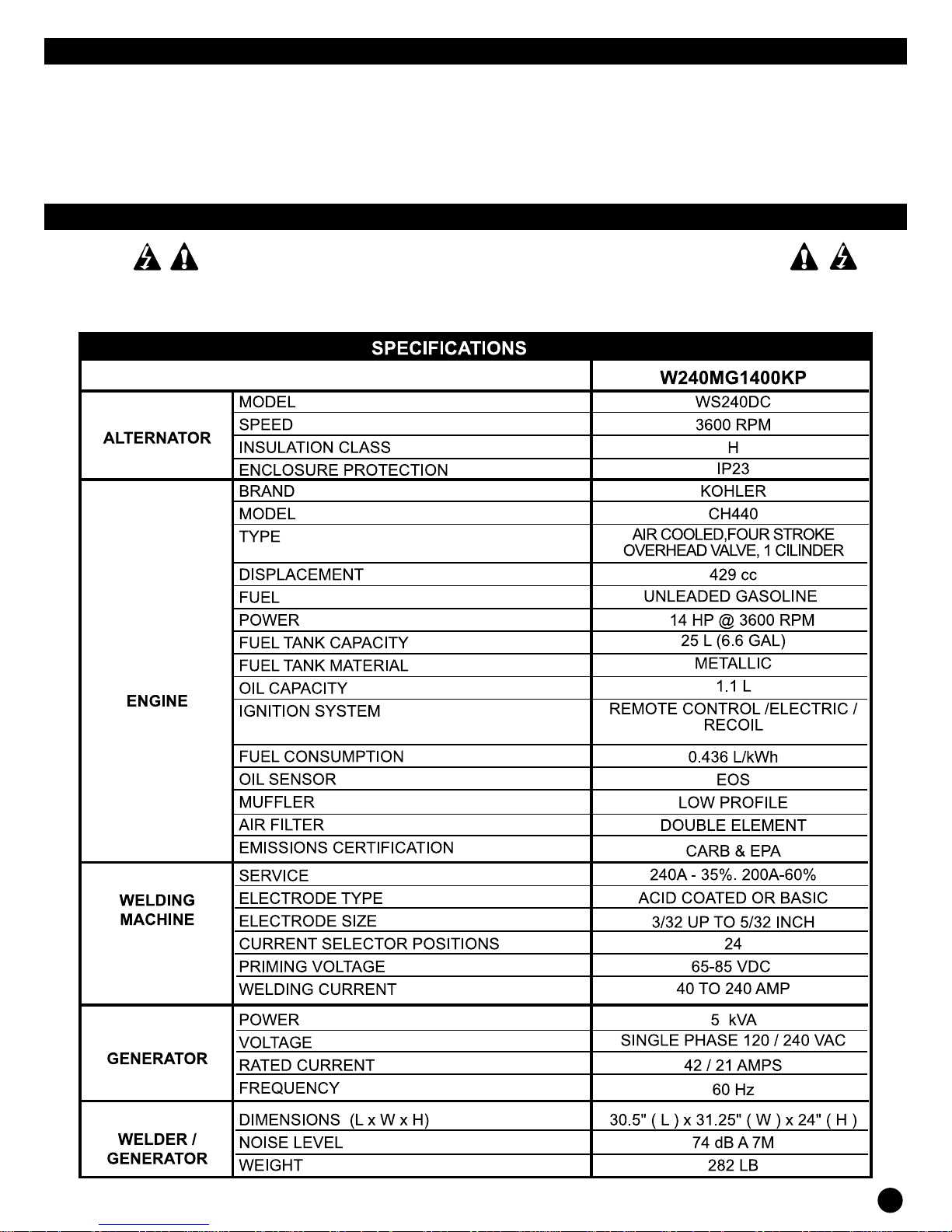
SPECIFICATIONS SUBJECT TO CHANGE WITHOUT NOTICE
IMPORTANT
To help us serve you better do not hesitate to contact us if you have any problems or suggestions.
This manual has important information for installation, operation and maintenance of your equipment. It is very
important to read this manual carefully before starting your equipment.
Always keep this owner´s manual in a safe place for further reference.
INDICATIONS
IMPORTANT SAFETY INFORMATION INDICATES HOW TO PREVENT
DAMAGE TO EQUIPMENT AND PERSONAL SAFETY INSTRUCTIONS
SPECIFICATIONS SUBJECT TO CHANGE WITHOUT NOTICE
3

DESCRIPTION
These units are provided with four strokes air cooled
1
engines designed to run at 3750 RPM max. and
continuously deliver a current corresponding to its
rated power. In these models a device is provided for
automatic engine turning off when the engine has low
oil level, so protecting it. This characteristic is generally
associated with long running models.
The alternator is thermally protected. To operate this unit
2
as a generator or a welder, place the front panel switch
according to what you want.
UNPACKING
When you unpack, inspect carefully for any damage
1
that may had occurred during shipment. Make sure that
any xture, screws, etc., are tightened before operating
the unit.
SAFETY MEASURES
Report any missing item by contacting the place of
1
purchase.
Before starting or servicing the welder/generator, read
2
and understand all instructions. Failure on complying
with safety precautions or instructions can cause
damage to the equipment and/or personal injury or
death.
NEVER OPERATE THIS WELDER/GENERATOR IN AN
EXPLOSIVE OR FLAMMABLE ENVIROMENT OR IN
AREAS WITH INSUFFICIENT VENTILATION.
12
Be sure that all tools and accessories are well prepared
for use and are properly grounded. Use one phase tools
or apparatus provided with three-prong plug power cord.
If an extension cord is used, be sure this has three- prong
plugs with a suitable ground connection..
DO NOT OPERATE YOUR EQUIPMENT ON WET
SURFACES OR UNDER THE RAIN.
TURN OFF AND DISCONNECT THE SPARKPLUG
WIRE BEFORE PERFORMING ANY SERVICE OR
MAINTENANCE TO THE UNIT.
13
Use only unleaded fuel. Do not ll the fuel tank with the
engine running. Take precautions to avoid spilling of
fuel while lling the tank. Make sure that fuel tank cap is
securely in place before starting the engine. Clean any
spilled fuel before starting the engine. Allow engine to
cool for at least two minutes before lling the tank.
This welder/generator can be used for auxiliary
14
emergency electrical service, in these cases, a double
throw switch shall be installed between the entrance main
switch and the electrical distribution box. This switch must
be installed by a licensed electrician
3
The instructions about the engine for these units are
included in a separate manual. Keep all the manuals
for future references.
Never use this welder/generator for any application
4
other than that specied by the manufacturer. Never
operate this welder/generator under conditions not
approved by the manufacturer. Never attempt to modify
the equipment to operate in a way other than that for
which it was designed.
For maintenance and repairs use only products and
5
original components.
Before operation, make sure your equipment is properly
6
connected to ground. For proper grounding procedures
refer to “grounding instructions” section in this manual.
7
Make sure that your equipment is used only by persons
who have read and understood these instructions.
8
If your welder/generator is going to be in a xed place,
hold it rmly to the oor (use anchors, expansive dowels
or similar) if not, make always sure that it will not move
with the vibrations.
9
Keep all persons away from the equipment during its
operation. Do not allow people wearing jewelry or loose
clothing manage the equipment, since these can be
caught by moving parts, causing damage to equipment
and/or personal injury. Keep the people away from
movable pieces or that which can become hot during
functioning.
Be sure that all electrical appliances are switched off
10
before connecting them to your equipment.
NEVER MIX OIL WITH GASOLINE. THIS FOURSTROKE ENGINE IS DESIGNED TO BE FUELED WITH
PURE GASOLINE. OIL IS ONLY USED FOR ENGINE
LUBRICATION
KEEP ALWAYS ACCESSIBLE A FIRE EXTINGUISHER
WHILE YOU ACCOMPLISHE ARC WELDING WORKS.
All installation, maintenance, repair and operation of this
15
equipment shall be carried out by persons qualied in
accordance with national, state and local codes.
THE INAPPROPRIATE USE OF ELECTRIC ARC
WELDING WELDERS CAN CAUSE INJURY,
ELECTRIC SHOCK AND EVEN DEATH. TAKE ALL
PRECAUTIONS DESCRIBED IN THIS MANUAL TO
REDUCE THE POSSIBILITY OF ELECTRIC SHOCK
Check that all components of the arc welder are clean
16
and in good condition prior to operating the welder. Make
sure that the insulation of all cables, electrode holders
and power cords are not damaged. Always repair or
replace damaged components before operating the
welder. Always keep panels, guards, etc. of the welding
machine in place when you operate.
17
Wear always dry protection clothing, welder gloves and
insulated footwear.
Always operate the welding machine in a clean, dry and
18
well-ventilated area. Do not operate the welding machine
in humid, wet, rainy areas or with insufcient ventilation.
19
Make sure that the work piece is properly supported
and grounded prior to begin any electric arc welding
operation.
Keep always the welder/generator clean and well
11
maintained.
4
20
You must stretch the welding cable before use to avoid
overheating and damage to the cable insulation.
SPECIFICATIONS SUBJECT TO CHANGE WITHOUT NOTICE

NEVER IMMERSE THE ELECTRODE OR ELECTRODE
HOLDER IN WATER. IF THE WELDING MACHINE
IS WET FOR ANY REASON, BE SURE THAT IT
IS COMPLETELY CLEAN AND DRY BEFORE
ATTEMPTING TO USE IT.
21
Always shut down your equipment before moving the unit.
22
Always attach rst the work conductor.
Check that the work piece is positively grounded.
23
24
Always shut the electric welder off and remove the
electrode from the holder when welder is not in use.
25
Never allow any part of the human body to touch the
work electrode and ground or the grounded work piece
at the same time.
26
The human body conditions and inconvenient body
positions while welding can cause electrical shock
hazard. When crouching, kneeling or at elevations, be
sure to insulate all conductive parts, wear appropriate
protective clothing and take precautions to prevent
injuries caused by falls.
27
Never attempt to use this equipment with current
settings or duty cycles higher than those specied on
the equipment labels.
28
Never use an electric arc welder to thaw frozen pipes.
THE DETACHED SPARKS AND HOT METAL CAN
CAUSE INJURIES.
AS THE WELDS TURNS COLDER IT IS POSSIBLE
THAT DETACHMENT OF SLAGS OCCUR. TAKE ALL
PRECAUTIONS DESCRIBED IN THIS MANUAL TO
REDUCE THE POSSIBILITY OF INJURIES CAUSED
BY SPARKS AND HOT METAL DETACHMENTS.
29
When chipping or grinding metal parts wear approved
by ANSI protective helmet or safety glasses with side
protection. Use ear plugs when welding above your head
to prevent spatter or slag falling into your ears.
ELECTRIC ARC WELDING OPERATIONS PRODUCE A
BRIGHT LIGHT AND HEAT, AND ULTRAVIOLET (UV)
RAYS. THIS MAY CAUSE INJURIES TO THE EYES
AND SKIN. TAKE ALL PRECAUTIONS DESCRIBED
IN THIS MANUAL TO REDUCE THE POSSIBILITY OF
INJURY.
30
All persons using this equipment or who are in the area
while the equipment is being used shall use protective
equipment that includes: helmet or protective welding
glass shade 10, wear resistant to ames, leather welding
gloves and full foot protection.
NEVER SEE THE OPERATIONS OF ARC WELDING
WITHOUT EYE PROTECTION DESCRIBED ABOVE.
NEVER USE DARK FILTER LENSES THAT ARE
CRACKED, BROKEN OR UNDER 10 SHADOW
CLASSIFICATION. WARN OTHERS IN THE AREA
THAT THEY DO NOT SEE THE ARC.
ELECTRIC ARC WELDING OPERATIONS CAUSE
SPARKS AND HOT METAL AT TEMPERATURES THAT
CAN CAUSE SERIOUS BURNS. WEAR GLOVES AND
PROTECTIVE CLOTHING WHEN PERFORMING ANY
METAL WORK.
TAKE ALL PRECAUTIONS DESCRIBED IN THIS
MANUAL TO REDUCE THE POSSIBILITY OF BURNS
ON THE SKIN AND CLOTHING.
31
Make sure that all persons in the area of doing welding
are protected from heat, sparks, and ultraviolet rays. Use
additional protection for face and ame resistant barriers
as needed.
32
Never touch work pieces until they have completely
cooled down.
HEAT AND SPARKS PRODUCED DURING SOME
WELDING WORKS AND OTHER METAL WORKING
OPERATIONS CAN IGNITE FLAMMABLE AND
EXPLOSIVE MATERIALS. TAKE ALL PRECAUTIONS
DESCRIBED IN THIS MANUAL TO REDUCE THE
POSSIBILITY OF FLAMES AND EXPLOSIONS.
Remove all ammable materials within a radius of 35 feet
33
(11 meters) away from the place where the welding work
is being performed. If it is not possible to remove them
tightly cover ammable materials with reproof covers.
34
Take precautions to make sure that sparks ying and
the heat do not cause ames in hidden areas, behind
screens, etc.
FIRE HAZARD. DO NOT WELD ON CONTAINERS
OR PIPES THAT CONTAIN OR HAVE CONTAINED
FLAMMABLE OR COMBUSTIBLE LIQUIDS
MATERIALS.
SOLDERING OF CYLINDERS OR CLOSED TANKS OR
DRUMS CAN CAUSE EXPLOSION IF APPROPRIATE
HOLES HAVE NOT DONE ON THEM.
VERIFY THAT ANY CYLINDER OR CLOSED
CONTAINER TO BE SOLDERED HAS A SUITABLE
VENTILATION HOLE, SO THAT EXPANDING GASES
CAN BE RELEASED.
DO NOT BREATHE FUMES PRODUCED BY THE
ARC WELDING PROCESS. THESE GASES ARE
DANGEROUS.
IF THE AREA OF WELDING CAN NOT BE VENTILATED
PROPERLY, BE SURE TO WEAR A RESPIRATOR
WITH A TANK OF OXYGEN.
Keep head and face away from the welding gases.
35
36
Do not perform electric arc welding operations on metals
that are galvanized or cadmium plated, or contain zinc,
mercury, or beryllium, without completing the following
precautions:
a. remove the coating from the base metal.
b. make sure that the area of soldering it is well ventilated.
c. use a respirator with oxygen.
Extremely toxic gases are created when these metals
are heated.
THE ELECTROMAGNETIC FIELD THAT IS
GENERATED DURING ARC WELDING CAN INTERFER
THE OPERATION OF VARIOUS ELECTRICAL AND
ELECTRONIC DEVICES, FOR EXAMPLE CARDIAC
PACEMAKERS. PEOPLE WHO USE SUCH DEVICES
SHOULD CONSULT WITH A DOCTOR BEFORE
MAKING ANY ELECTRIC ARC WELDING OPERATION
SPECIFICATIONS SUBJECT TO CHANGE WITHOUT NOTICE
5
Route the electrode and work cables together and secure
37
with tape when possible.
38
Never wrap the welder cables around the body.
39
Always place the electrode and work connectors so that
they are on the same side of the body.
40
Exposure to electromagnetic elds during welding may
have other health effects which are unknown.
MAKE ALWAYS SURE THE AREA OF SOLDERING
IS SAFE AND FREE OF HAZARDS (SPARKS,
FLAMES, THE RED METAL OR SLAG) BEFORE IT
IS ABANDONED. MAKE SURE THE MACHINE IS
SHUTDOWN AND THE ELECTRODE HAS BEEN
REMOVED. MAKE SURE THAT THE WELDING
CABLES ARE LOOSE WOUND AND OUT OF THE
WAY. MAKE SURE THAT ALL METAL AND SLAG HAS
BEEN COOLED.
ADDITIONAL SAFETY MEASURES
Those who live and work in the United States must realize
that according to the laws of this country the following codes
apply for work with welders: ANSI Standard Z49.1, OSHA
29 CFR 1910, NFPA Standard 70, CGA Pamphlet P-1, CSA
Standard W117.2, NFPA Standard 51B ANSI Standard Z87.1.
Those people who are resident in Latin American countries
should consult local codes and regulations that apply in their
respective countries. Also all users should consult the safety
measures provided by the manufacturers of the products to
be used.
PRECAUTIONS FOR NOISE
The welder/generator can produce high levels of sound, a
prolonged exposition to above 85 dB sound level is harmful
to the ear. Wear ear protection when operating around the
generator while it is running
LOCATION GENERAL
LOCATION
The selection of the appropriate location to store the
welder/generator after use can increase signicantly the
performance, reliability and life of the equipment.
1
For best results store the welder/generator in an
environment that is clean and dry. Dust and dirt in the unit
maintain moisture and increase wear of moving parts.
Store electrodes in a clean, dry location with low humidity
2
to preserve the ux coating.
GENERAL OPERATION
Check engine oil level. Oil shall not be mixed with
1
gasoline, however, adequate oil supply is necessary for
the lubrication of the engine. Refer to the engine manual
for the oil type and quantity specications.
THE UNIT IS SHIPPED WITHOUT OIL IN THE ENGINE.
OPERATION OF THE EARTH INTERRUPTER WILL
NOT BE EFFECTIVE IF THE WELDER/GENERATOR
IS NOT PROPERLY CONNECTED TO EARTH.
REFER TO THE SECTION TITLED GROUNDING FOR
APPROPRIATE STEPS TO GROUND YOUR WELDER/
GENERATOR
3
When installing a GFI, be sure to comply with all national
and local regulations. If you are not sure about the
regulations or procedures, obtain assistance from a
qualied electrician.
4
LUBRICATION
Do not attempt to start this engine without lling the
crankcase with the amount and type of suitable oil. (Use
SAE 10W-30). Your unit has been shipped from the
factory without oil in the crankcase. Operating the unit
without oil can ruin the engine.
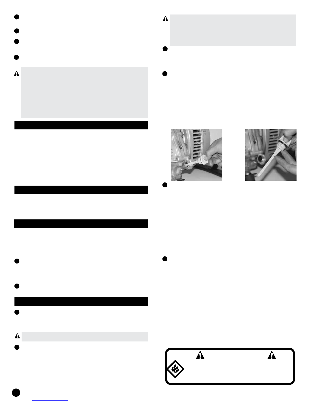
Fill the engine with oil according to the engine manual.
In this engine, the plastic cap on the casing contains a
bayonet with marks of full and empty.
5
THE LOW OIL LEVEL SENSOR
This unit is equipped with an oil low level sensor. Initially, if
the oil level is lower than the required, sensor will activate
a protective device to stop the engine. (See the attached
engine manual for more information).
If unit shuts off and the oil level is within specifications,
check that the unit is not positioned at an angle that forces
oil to vary its level. Place it on an even surface to correct
this problem. If the engine does not start, oil level could
be not sufficient to deactivate low oil level switch. Make
sure that the oil plug mark is at correct level.
6
FUEL
Fill the tank with unleaded gasoline for cars, clean, fresh.
You can use regular grade gasoline provided than it is
high octane rating (at least 90 octane). We recommend
that you always use a gasoline additive. A gasoline
additive will minimize the formation of fuel gum deposits
during storage. Gasoline additive can be added to the
gasoline in the tank or added to the fuel or gasoline in a
storage container.
Fuel and engine smoke are flammable, and potentially
explosive. Use an appropriate procedure to store and
handle fuel. Always maintain ABC fire extinguishers on
hand.
2
It is strongly recommended the use of a ground fault
interrupter (GFI). Ground fault circuit breakers can
signicantly reduce the possibility of injury if a short circuit
occurs. To install a GFI, the neutral wire of the welder/
generator must be internally grounded to the frame of
the welder/generator, and the frame must be properly
grounded.
6
CAUTION
Do not overfill the tank. Maintain a maximum
level of fuel to 1/4 inch below the top of the
fuel tank. This will allow expansion in hot
weather, thus avoiding spillage.
SPECIFICATIONS SUBJECT TO CHANGE WITHOUT NOTICE

GROUNDING
SETTLEMENT OF THE ENGINE
Be sure that the welder/generator is grounded to prevent
1
accidental electric shock. It has an earth terminal
provided for this purpose.
2
The ground wire size must be 8 AWG and you can
connect to the terminal using at tip screwdriver to lift
the terminal screws that tighten the cable.
3
The other end of the ground wire must be fastened
securely to an approved grounding source.
Following this is described ground sources approved by
the national electric code.
Other ground sources may be acceptable.
Refer to the national electric code and local regulations
for more information on sources of ground. If you are
not sure about the regulations or procedures, obtain
assistance from a qualified electrician (licensed or
certied)
a. an underground water pipe of at least 10 feet (3 m)
length.
b. a non-corrosive underground pipe at least 8 feet (2.4
meters) long and ¾ inches in diameter.
c. underground bar of copper of at least 8 feet (2.4 m)
length and 5/8 inches in diameter.
d. a Nonferrous rod of at least 8 feet (2.4 m) in length and
½ inch in diameter and approved for grounding purposes.
Any bar or pipe used to make a ground connection must
be carried to eight feet (2.4 m) deep or buried in the
deepest possible trench.
START PROCEDURE
1
Remove all electrical loads from the welder / generator.
After initial start-up, the engine must pass a settlement
run according to the manufacturer’s instructions. Refer to
the engine manual for instructions on proper settlement
run procedure.
TURN OFF
Turn off and remove all devices of electric charge from
1
the welder/generator.
2
Allow the engine to run for 2-3 minutes without electrical
loads.
3
Turn the engine switch to the (OFF) position.
4
Check that the welder/generator has completely stopped.
5
Close the fuel supply valve.
6
Allow the unit to cool before installing any cover
LOW OIL LEVEL SHUT DOWN
These models are of long run, an automatic low oil level
shutdown switch is provided to protect the engine and
the welder/generator.
When the engine oil level drops below the level needed for
a proper functioning of the engine, low oil level shutdown
switch makes the engine turns off. If the oil level is low
when trying to start the engine of the equipment, the
low oil level shutdown switch prevents the engine from
starting. If the engine does not start, check the oil level.
Note: It is important to keep the unit on an even surface.
The oil level shutdown switch can prevent the engine from
starting even if oil level is sufcient, when the welder/
generator is placed on an inclined surface.
OPERATION AS A GENERATOR
2
Turn fuel shut-off valve in counterclockwise direction to
allow the fuel to ow.
3
Turn the engine switch to the (ON) position.
Adjust lever choke in the following way:
a. for a cold engine, move the choke lever as much as
possible to the left, ooded completely in ON (open)
position.
b. for a warm/hot engine move the choke lever to an
intermediate position between the positions of drowned
and run.
4
Pull the starter rope with a rm and smooth motion.
Note: Some models may be equipped with an electric
starter. For models equipped with an electric starter,
turn the key.
5
After each start-up, allow the engine to run for 2-3 minutes
without load.
6
As the engine heats up and stabilizes, setting drowning
right lever, until it is positioned on the RUN label.
THE ENGINE SPEED IS DEFAULT TO PROVIDE
ADEQUATE VOLTAGE OUTPUT. NEVER ATTEMPT
TO MODIFY OR ADJUST THE MOTOR SPEED OR
OUTPUT VOLTAGE.
THE FRONT PANEL SWITCH MUST BE PLACED IN
GENERATOR.
PREPARATION AND INSTALLATION OF
THE GENERATOR
1
Place generator outdoors where it will be used. This
should be on a at surface, and away from ammable
materials. Do not allow the generator to get wet.
2
Fill the tank of fuel (outdoors) up to 21 litres of gasoline,
do not ll the tank up to the top.
3
Add 1.1 liters of oil to the engine by removing the bayonet
that is located on the side of the engine. Use SAE 10W-30
oil. Use a funnel to avoid spillage of oil. Check the oil level
with the bayonet; this should be marked “full”. Carefully
replace the oil plug, so avoiding damaging of the threads.
Before connecting the equipment to the generator,
4
check they are in off position. Go to the section HOW TO
DETERMINE POWER in this manual. Do not overload
the generator. Calculate the total power of the equipment.
The maximum power of the generator is indicated in the
specication sheet.
SPECIFICATIONS SUBJECT TO CHANGE WITHOUT NOTICE
7
GENERATOR CONNECTIONS
WARNING
If the generator will be used to replace energy
during electrical utility lack of services,
power input must be insulated . Refer to the
electrical safety measures of the generator in
the INSTALLATION section in this manual. These
connections must be made only by a qualified
electrician.
GENERATOR START
CAUTION
WARNING
Gasoline is very dangerous. If gasoline makes
contact with hot surfaces can cause serious
injury or death.
1. Do not fill the fuel tank with the engine running.
2. Turn off engine and wait 2 minutes before filling fuel
3. Do not spill fuel when filling the tank.
4. Do not mix oil with gasoline.
5. Follow the instructions and warnings contained in
the engine manual.
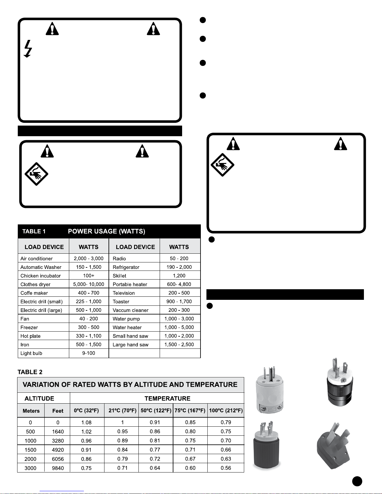
HOW TO DETERMINE THE POWER
In order to prevent overloading and possible damage to
your generator, it is necessary to know the total power
of the connected load. To determine which tools and/or
appliances your generator will run, follow the steps below:
1
Determine if you want to operate a device or multiple
devices simultaneously.
2
Verify start and function power of the apparatuses to
be connected to the generator by checking the power
required in the product label or have help using the values
of table 1 or by calculations (multiply amps x volts).
3
Summarize all the start and function powers. If label gives
only the voltage and amperage, multiply volts x amp =
watts. 1kW = 1,000 watts.
This product contains or produces
chemicals when it is used, considered by
the State of California to cause cancer,
birth defects and other serious damage.
(California Code of Health and Safety
25249.5 et seq.)
All engine exhaust contains carbon monoxide,
a deadly gas. Breathing carbon monoxide can
cause headache, dizziness, nausea, confusion
and eventually death. Carbon monoxide is deadly,
odorless and invisible gas, and it can be present even
though you cannot see or smell it. Deadly levels of carbon
monoxide can be accumulated quickly, and you may lose
ability to save yourself. Also, deadly levels of carbon
monoxide can be stored for hours or days in closed or
poorly ventilated areas. If you experience any symptoms
of poisoning, get fresh air and seek for medical help. To
prevent serious injury or death by carbon monoxide:
NEVER operate engine indoors. Although the case of
having ventilating fans, windows or open doors, carbon
monoxide can quickly reach dangerous levels.
NEVER turn on engines in areas poorly ventilated or
partially closed. Areas such as warehouses, garages,
basements, homes, rooms, etc.
NEVER turn on engines when the engine exhaust gases
may go into buildings through openings such as windows
or doors.
During starting the motor-driven appliances or tools
4
require more power than what is specified on its
nameplate. Note: Consider 2 ½ - 4 times the power
marked on the nameplate for start.
5
The welder/generator’s rated watts shall match or exceed
the number of watts required by all the apparatuses you
want to be supplied by the generator.
6
The continuous generator power decreases according to
the temperature and altitude of the place where you are
using the equipment. Use the power correction table and
multiply the rated power indicated in the specicatrion
shhet by the correction factor.
Always connect the bigger load rst, and then add the
7
other apparatuses one by one.
VOLTAGE REQUIREMENT
You must use a conditioner (regulator) line when one
or more of the following solid state equipment will be
connected to the generator:
• Control for garage door openers.
• Kitchen appliances with digital displays.
• Televisions.
• Stereo.
• Personal computers.
• Quartz watches.
• Photocopy machines.
• Telephone equipment
8
SPECIFICATIONS SUBJECT TO CHANGE WITHOUT NOTICE
CAUTION
The requirements of operating voltage and
frequency of all electronic equipment shall
be checked prior to plugging them into this
generator. Damage may occur if the equipment
is not designed to operate within a voltage variation
of +/-10% and frequency variation of +/-3 Hz of the
rating appearing on the nameplate of the generator.
In order to avoid damage, always have an additional
burden other than solid state load plugged into the
generator in case of using only solid state (such as
a television set) loads.
A line conditioner may be necessary for some
applications of solid state equipment.
INSTALLATION
WARNING
To avoid possible personal injury or property
damage, it is necessary that the installation and
all service be performed by a qualified electrician
or authorized service representative. Under no
circumstances shall be permitted that a non
qualified person make cable or wiring works into the
electrical utility circuits.
1
In order to avoid the feedback to the electrical utility
systems, isolation of the location or facility electrical
system is required.
2
Before make the temporary connection of the generator
to the location or facility electrical system, turn off or
disconnect the main service.
3
If the generator is to be used as a source of backup power
in the event of a power failure, it must be installed by a
licensed electrician in accordance with all applicable local
electrical codes.
4
Proper use requires the installation of a transfer switch
double throw by a qualified electrician trained and qualified
to ensure that the building’s electrical circuits may be
switched safely between utility power and the generator’s
output, avoiding the feedback to the power supply system.
WARNING
To avoid feedback towards the power supply
systems, isolation of the location or facility
electrical system is required. Before temporary
connection of the generator to the location or
facility electrical system, turn off the main switch.
Before making permanent connections, you must install
a double-throw transfer switch. To avoid electrocution or
property damage, only qualified electricians can connect
the generator to the location or facility electrical system.
California laws require the isolation of the residence
electrical system before connecting a generator to the
residential electrical systems.
Always follow the codes and ordinances that apply
5
to the installation of any equipment related to this
product.
NFPA 70 - National Electrical Code.
NFPA 30 - Standard for installation and use of
stationary engines of fuel.
Agricultural facilities wiring manual for auxiliary electric
power for farms.
ELECTRICAL EXTENSIONS
All loads supplied from the generator will be connected
1
to the panel using extensions or cables and it must be
done by means of 3-prong grounded 125 volts 15A
and 20 A plugs, 4-prong grounded 125/250 volts
30 A twist lock plugs, or 4-prong grounded 125/250 V
50 A. The receptacles must not be loaded above the
amperage rating.
5-15P
5-20P
SPECIFICATIONS SUBJECT TO CHANGE WITHOUT NOTICE
L14-30P
14-50P
9
2
Refer to the nameplate on the welder/generator for the power
and amperage ratings.
Note: The required power can be calculated by multiplying the
volts and the amperes. The resulting number is the power in
watts.
Always switch off and remove the electric load before turn on or
3
off the welder/generator engine.
4
Refer to the table for minimum sizes of extension cord in
accordance with the needs of loads.
5
When the load increases you must use an extension cord of
bigger size. Use of inappropriate AWG size extensions can cause
serious problems with voltage, resulting in a loss of energy and
damage of the tools.
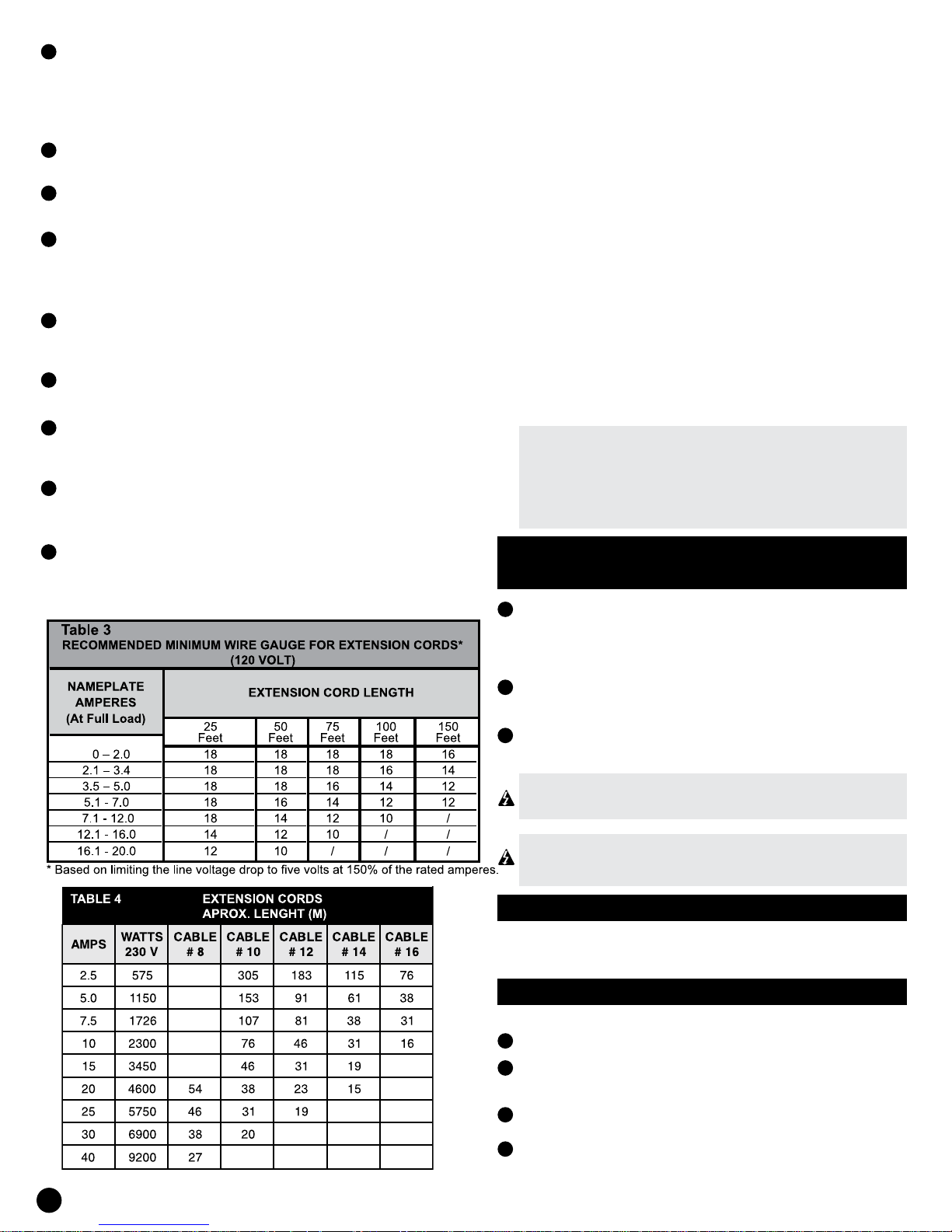
The smaller the AWG number is, the higher the conductor
6
amperage. A 14 AWG conductor, for example, can carry out a
current higher than that corresponding to a 16 AWG one.
7
When there are connected multiple extensions it must checked
that each extension is of the minimum recommended cable size.
8
If an extension is used with outputs for more than one apparatus
sum the amperes of the nameplate of each one of the devices
to determine the minimum extension cord size.
9
The extensions for 120 V outputs shall be 3-wire ones, where the
green wire is the ground wire, the white or gray lead is connected
to the neutral of generator, and the black wire is the hot wire.
If not load real watts are known, table 1 can be used as
a general guide.
Remember that apparatuses which generate heat during
operation such as heaters, incandescent lamps, motors
and hair dryers, require a power higher than devices that
generate little heat during operation such as uorescent
lamps, radios and clocks.
Power cords and extension cords may require additional
power depending of the cord length . Keep cords of
the smaller possible length. See tables 3 and 4 for
the recommended extension cords size and length
depending on the amperage or wattage.
The circuit protection is provided by two OPS (thermal
breaker) that opens when the welder/generator load
exceeds its maximum capacity or a short circuit occurs.
If the OPS is activated, use the following procedure to
correct the problem:
a. turn off and unplug all electrical load.
b. try to determine the cause of the electrical problem overload or short circuit.
c. do not use any device that has a short circuit. Avoid
overloading the welder/generator
d. press the OPS button to reset it.
A REPEATED OPERATION OF THE OVERLOAD
PROTECTOR INDICATES A PROBLEM AND
CAN CAUSE DAMAGE TO THE PRODUCT OR
ELECTRICAL DEVICES. DO NOT OPERATE THE
WELDER/GENERATOR IF THE OPS IS REPETEADLY
ACTIVATED.
Extensions for 125/250 outputs shall be 4-wire ones, where the
10
green wire is the ground wire, the white or gray lead is connected
to the neutral of generator, and black and red wires are the hot
wires.
INSTRUCTIONS FOR USE AS
EMERGENCY GENERATOR
1
Caution to avoid feedback to public services systems.
This requires an isolation of the electrical system. To
isolate the electrical system, perform the following
procedures.
2
Turn off the main electrical system switch prior to
connecting the equipment.
In accordance with national and local standards, two-
3
throw transfer switch must be installed in the system.
ALWAYS DISCONNECT THE MAIN SUPPLY BEFORE
TEMPORARILY CONNECTING THE WELDER/
GENERATOR TO A BUILDING ELECTRICAL SYSTEM.
THE INSTALLATION OF YOUR WELDER/GENERATOR
AS A BACKUP POWER SOURCE MUST BE
PERFORMED BY A QUALIFIED ELECTRICIAN.
CAUTION BEFORE STARTING
Before starting the unit, check for loose or missing parts
and any kind of damage that may have occurred during
the sent.
STARTING THE ENGINE
10
Check the oil level.
1
2
Disconnect all electrical loads from the unit. Open the
fuel shut-off valve.
3
If the engine is cold move the choke to the right lever.
4
Move the start switch to the “ON” position.
SPECIFICATIONS SUBJECT TO CHANGE WITHOUT NOTICE
Pull the retractable motor cord (with a fast steady pull), if
5
manual start, or turn the ignition switch key, if it is electric
start (turn the ignition key to the “START” position, and
then release the key after the engine starts).
After starting back choke lever to its original position (to
6
the left)
OPERATION WELDER
THE SWITCH ON THE FRONT PANEL MUST BE
PLACED IN ANY WELDING POSITION AS REQUIRED.
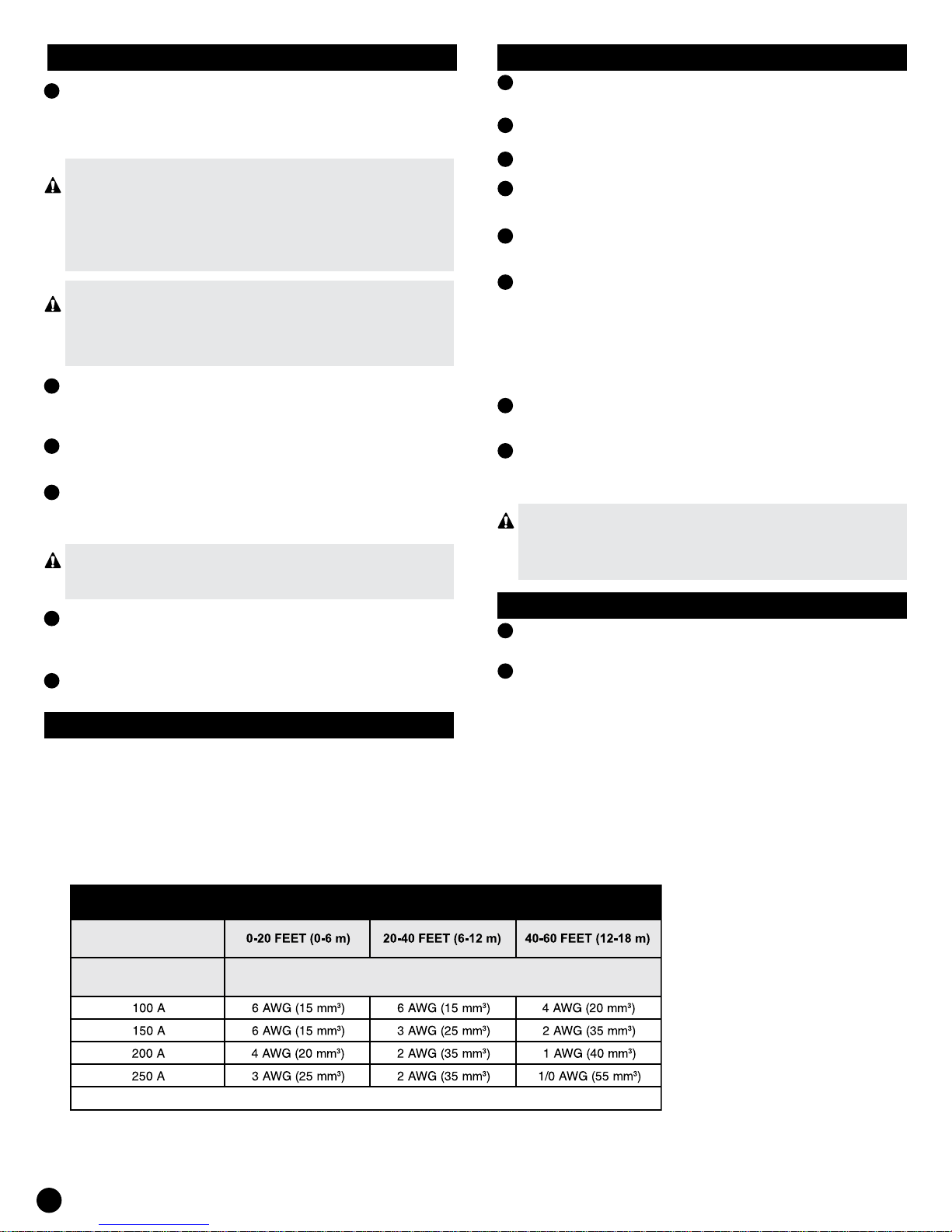
Welding cables and clamps are not included with the
units. Use welding cable of the size specied in table 5.
CAUTION
Allow the welder/generator to run with no load for five
minutes after each initial start-up to allow the engine
and the alternator to stabilize.
DANGER
• It must be provided adequate ventilation for
toxic gases and air flow for engine cooling (the
engine is cooled by air that is injected by its
own fan)
• Do not start or start the welder/generator in
an enclosed area, even if doors or windows are open.
• The motor has carbon monoxide, a poisonous, odorless
and invisible gas.
• Vacuum carbon monoxide can cause nausea, fainting
or even death.
HOW TO APPLY A LOAD
This unit has been pretested and adjusted to handle its
full capacity. To start the generator, disconnect all loads.
Apply load only after the welder/generator is running.
Voltage is regulated via the engine speed adjusted at
the factory for correct output. Move the motor speed will
make you lose the warranty.
GENERATOR’S TURN OFF
1
Remove all electrical loads.
2
Let the engine run for a few minutes without load.
3
Move the motor key to the “OFF” position. (Turn the key
to “OFF” on the electric start models)
Do not leave the welder/generator until operation is
4
stopped completely.
Close the fuel valve if the motor must be placed in storage
5
or transport.
6
If you are going to place a cover over the equipment for
protection, wait until the unit has became cool.
INITIAL START UP
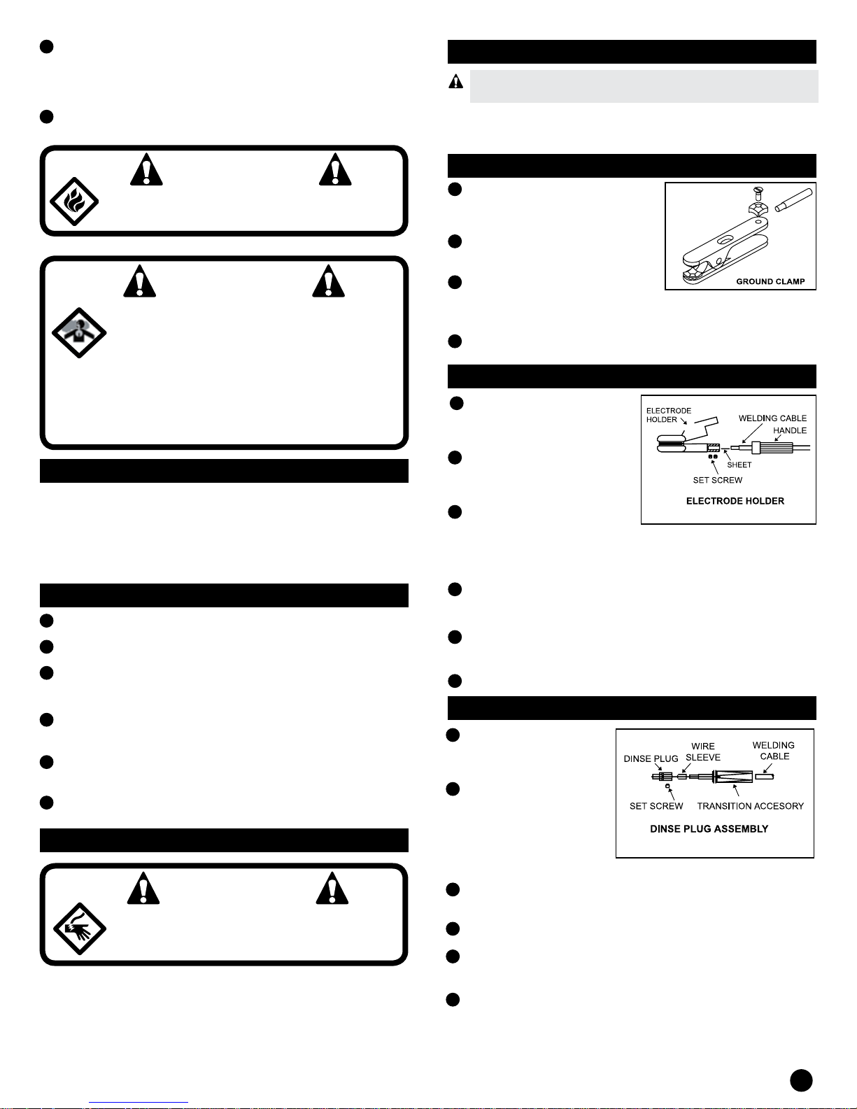
CLIP FOR GROUNDING (FIG.1)
Remove ½” (1.3 cm) of
1
insulation from the end of one
wire welding.
2
Loosen the hex nuts on work
clamp.
3
Insert the end of the welding
cable through clamp handle and slide the wire bare under
the clamp block.
4
Tighten hex nuts securing the cable in place.
ELECTRODE HOLDER (FIG.2)
Remove 1” (2.5 cm) of
1
insulation from the end of
the other wire welding.
2
Remove handle insulated
electrode holder and slide
it over the welding cable.
3
Loosen the two set screws
which are located in the
lower part of the electrode holder making sure that the
blade is between cable and xing screws.
Slide the wire without insulation within the back of the
4
electrode holder making sure that the blade is between
cable and xing screws.
5
Tighten the two fastening screws securing the cable in
place.
6
Slide the handle into place in the electrode holder.
PLUGGING DINSE
Remove ½” (1.27 cm)
1
of insulation from the
end of one wire welding.
2
Insert this end of the
welding cable through
the transition from the
“dinse” plug and slide
the bare into the sleeve
of the cable wire.
CAUTION
Do not apply a strong electrical charge
during the initial period of operation (the
first 2 or 3 hours of operation).
A controlled initial startup procedure helps to ensure
correct operation of the engine and generator. Follow
the procedure described in the engine manual engine.
SPECIFICATIONS SUBJECT TO CHANGE WITHOUT NOTICE
Insert assembly sleeve cable soldering wire into the back
3
of the plug “dinse”.
4
Tighten the fastening screws securing the cable in place.
5
Slide the attachment of transition over the hex portion
of the plug “dinse”.
6
Repeat the same steps for the other side.
11
WELDING STORAGE
1
Check that the surfaces of metals to be welded are free
from dirt, rust, paint, oil and other contaminants. These
pollutants make difcult the welding operation and cause
poor welds.
ALL THOSE PERSONNEL WHO USE THIS EQUIPMENT
OR WHO ARE IN THE AREA WHILE EQUIPMENT IS
BEING USED SHALL WEAR PROTECTION FOR
WELDING THAT INCLUDE: EYE PROTECTION
WITH PROPER SHADE (10 SHADE MIN), CLOTHING
RESISTANT TO FLAMES, WELDING LEATHER
GLOVES AND FEET TOTAL PROTECTION.
IF WELDING OR CUTTING MATERIALS ARE
GALVANIZED, OR ZINC, LEAD OR CADMIUM PLATED
REFER TO THE SECTION OF SAFETY INFORMATION
FOR INSTRUCTIONS. WHEN THESE METALS ARE
HEATED EMIT EXTREMELY TOXIC GAS.
2
Connect work clamp to the work piece. Make sure that
the contact made on bare metal and are not clogged with
paint, varnish, rust or non-metallic materials.
3
Insert the exposed part of the electrode (the end without
ux) within the jaws of the electrode holder.
4
Place the adjustment knob amperage in the rating suitable
for the diameter of the electrode. Refer to the table on the
front panel for proper electrode current values.
THE ELECTRODE HOLDER AND ROD ARE
ELECTRICALLY ENERGIZED WHEN THE ENGINE
IS RUNNING.
5
Position the electrode to begin weld, lower welding helmet
or position the hand shield and set the arc. Adjust the
amperage welding as required.
6
When nished welding, turn the engine off and store the
unit properly.
DUTY CYCLE / THERMAL PROTECTION
Welder duty cycle is the percentage of actual weld time
that can occur in a ten minute interval. For example, at
a 10% duty cycle can occur during one minute, and then
the welder must be left to cool for nine minutes.
If the equipment is not used for long periods of time, the
1
following prior to storage procedures must be performed:
2
Check the oil level and add oil if necessary.
3
Run the equipment until fuel is exhausted.
4
Remove the spark plug and pour about a teaspoon of oil
into the spark plug hole.
5
Pull the starter rope several times to distribute the oil
throughout the cylinder and combustion chamber.
6
Slowly pull the starter rope until you feel resistance.
This indicates that the piston is moving upward in the
compression cycle and that the intake and exhaust valves
are closed. (The piston pushes a small amount of air
from the spark plug in the compression hole) The use of
fuel stabilizers helps prevent gum and varnish buildup
in fuel system.
7
Whenever the equipment is stored, make sure that the
fuel shut-off valve is in closed position.
8
Refer to the engine manual accompanying this unit
for instructions regarding maintenance of engine
components.
NEVER MODIFY THE SPEED AND FREQUENCY
SETTINGS THE WELDER/GENERATOR HAS AS
DONE AT THE FACTORY. ANY ADJUSTMENT MUST
BE PERFORMED BY QUALIFIED PERSONNEL.
WELDING CABLES
1
Check condition of weld cables and repair or replace
immediately any cables with damaged insulation.
2
Check condition of electrode holder insulating pieces and
immediately replace cracked or missing parts.
Every 3 months: Replace any unreadable labels on the
welder. Use compressed air to blow all the dirt and lint
from the ventilation openings.
The internal components of this welder are protected
against overheating with an automatic thermal switch.
TABLE 5
CABLE TOTAL LENGHT
MAXIMUM WELDING
CURENT
The cable lenght is the total of the ground cables and electrode
COOPER WIRE SUGGESTED SIZES FOR WELDING MACHINES
WELDING CABLES
12
SPECIFICATIONS SUBJECT TO CHANGE WITHOUT NOTICE

INSTRUCTIONS FOR WELDING
This type of welding machine use a process known as
shielded arc (SMAW) welding. This process is used to
join metals by heating them with an electric arc created
between the electrode and the work piece.
Used electrodes
in protected arc
welding have two
parts, the inner core
is a metal rod which
shall be similar in
composition to the
base metal and
an outer coating
layer which is
called flux. There
are several types
of ux. Different ux or coatings are used depending on
a situation of welding in particular.
While the metal is melted, it can be contaminated by
elements in the air. This contamination could weaken the
weld. The ux coating creates a protective barrier called
slag that protects the molten metal from contaminants.
When current (amperage) ows through the circuit to
the electrode, an arc between the end of the electrode
and the work piece is formed. The melted metal of the
electrode ows into the molten crater and forms a bond
with the work piece as shown in gure above
Note: Discontinue using and discard electrodes that burn
up to 1 to 2 inches (2.5 to 5 cm) from the electrode holder.
ESTABLISHMENT OF AN ARC
Place the bare end of the electrode in the electrode
holder. Take the electrode holder gently to reduce the
fatigue of the hand and arm.
Note: Always keep the jaws of the electrode holder clean
to insure good electrical contact with the electrode.
BE CAREFUL OF NOT TO TOUCH WITH THE
ELECTRODE THE WORKPIECE OR WORK BENCH
SINCE THIS WOULD CAUSE AN ARC.
The best method to
establish and maintain
an arc is the method of
scratching. Scratch the
electrode at an angle
along the surface like
you will do to light a
match. Once it makes
contact with the plate,
lift the electrode
approximately 1/16” (1.5
mm) from the surface
and the arc will be
established (see Figure aside).
Note: If the electrode stick to the work piece, peel it off
by turning it quickly or bending in the electrode holder
while pulling up.
If the electrode does not take off, release the electrode
by releasing it from the electrode holder.
SPECIFICATIONS SUBJECT TO CHANGE WITHOUT NOTICE
TYPE AND SIZE OF ELECTRODES
Four types of electrodes are recommended for this welder.
The electrodes are commonly known by the designation of
the AWS (American Welding Society) as detailed below.
E-6011 DEEP PENETRATION
• Flat bead with deep penetrating arc.
• For rusty or dirty mild steel general repair .
E-6013 GENERAL PURPOSE
• All positions, bar of soft deposit with little spatter
• For mild steel general work.
E-7014 FAST FILL
• Smooth bead and fast replacement
• Ideal for joints with poor t up and general repair work.
E-7018 - AC HIGH STRENGTH
• Ideal for pipes and structural applications.
• Low hydrogen reduces porosity for a resistant welding.
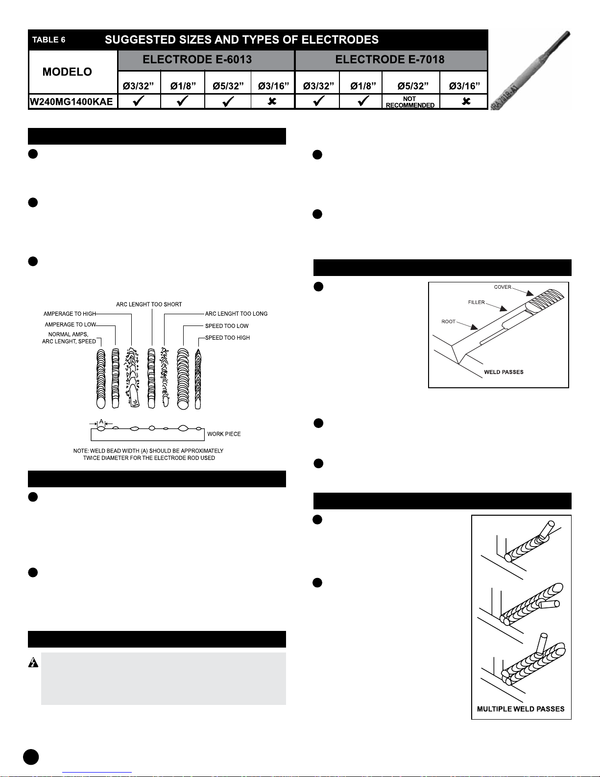
Note: Only E-6013 and E-7018 electrodes are recommended
for use with this welder. Other electrodes are designed to be
used with open circuit voltages greater than these welders are
capable of producing. Recommended electrode diameter is
3/32 “(2. 4 mm) to 5/32” (3.9 mm) for E-6013; and 3/32 “(2.
4 mm) to 1/8” (3.2 mm) for E-7018.
Basic instructions for arc welding
Four basic techniques affect the quality of the welding. These
are: amperage value, angle of welding electrode, arc length
and speed of movement. The proper use of these techniques
is necessary for obtaining a good quality weld.
THE AMPERAGE VALUE
The correct amperage involves the adjustment of the welding
machine to the required amperage value. This is regulated
by a knob on the welder. The amperage required depends on
the size (diameter) of the electrode used and the thickness
of the work piece.
Consult specications listed on the welder. Excessive amps
burn through light metals and the bead is at and porous. The
ange appears high and irregular if the amperage is too low.
WELDING ELECTRODE ANGLE
Weld electrode angle is the angle in which the electrode is
held during the welding process. The use of the correct angle
ensures adequate penetration and a formation of ange.
Electrode angle involves two positions: the angle of
displacement and working angle (see gure below).
Travel angle is the angle in the line of welding and may vary
from 5 to 45 degrees from the vertical, depending on the
conditions of soldering.
Work angle is the angle from horizontal,
measured at right angles to the line of
welding.
For most applications, a displacement
of 45 degree angle and an angle of 45
degree work is sufcient. For specic
applications, refer to the manual of arc
welding.
Note: Right handed welders should
weld from left to right. Left handed
welders should weld from right to left.
Electrode must always point towards
the sediment of welding as shown.
13
ARC LENGHT
1
The arc length is the distance from the work piece to the
tip of the electrode, the distance which must traverse the
arc. A proper arc length is essential to generate the heat
required for welding (see gure below).
2
An arc that is too long produces an unstable arc, reduces
penetration, increases the spatter and causes at and wide
beads. A too short arc does not create enough heat to melt
the work piece, the electrode tends to stick, penetration is
inadequate and uneven anges with irregularities will be.
3
A proper arc should not be greater than the diameter of the
bar. The sound of a proper arc is steady, clear sparking
similar to bacon fry.
1
After completing welding, wait to cool the welded sections.
A layer of protection, called slag now covers the ange
and this avoids that air pollutants react with molten metal.
Once the weld cools to the point that is not red hot, slag
can be removed.
2
The removal is carried out with a hammer chisel. Gently
hit the slag with the hammer and peel of the ange. The
nal cleaning is done with a wire brush. When they do
several steps of welding, remove slag before each pass.
WELDING POSITIONS
It can use four
1
basic positions; flat,
horizontal, vertical and
over head. Welding
in the flat position is
the easiest of any of
the others because
welding speed can be
increased, the molten
metal has less tendency
to corrode, penetration
can be achieved and the
work is less fatiguing.
TRAVEL SPEED
1
The travel speed is the speed at which the welding
electrode is moving moves along the area (see g. 7).
When the speed is very high, the bead is narrow and the
curl of the lip are pointed as shown. When the speed is
very low weld metal accumulates and the ange is high
and wide. To control the speed of the displacement, note
the ange (not the arc) when welding.
2
The ange is melted, orange metal behind the arc. The
width should be approximately twice the diameter of the
welding rod. Check the travel speed to obtain an even
ange width.
REMOVAL OF SLAG
USE ANSI (ANSI Z87.1) APPROVED SAFETY
GOGGLES AND PROTECTIVE CLOTHING WHEN
REMOVING SLAG. FIRED HOT REMANENTS CAN
CAUSE PERSONAL INJURY IN ANY AREA.
2
Other positions require different welding techniques as
dithering, circular step and short length soldering. A high
level of skill is required to perform these welds.
The work must be done in the at position if possible. For
3
specic applications, refer to the manual of arc welding.
STEPS OF WELDING
1
Occasionally more than one pass
is necessary to ll the joint. The
root pass is rst, followed by the
steps of lling and the cover pass
(see above and aside gures).
If the pieces are thick, it might be
2
necessary to bevel the edges that
are attached to an angle of 60
degrees. Remember to remove
the slag after each step.
14
SPECIFICATIONS SUBJECT TO CHANGE WITHOUT NOTICE
 Loading...