

Page 1

INSTALLER’S INSTRUCTIONS
IMPORTANT
It is advisable to check the following before turning on the boiler for the first time:
– Check that there are no liquids or flammable materials in the immediate vicinity of the boiler.
– Check that electrical connections have been made correctly and that the ground wire is connected to a proper
grounding system.
– Open the gas cock and check the seal on connections, including the burner connection.
– Check that the boiler is set up to run on the type of gas available.
– Check that the flue through which the products of combustion are eliminated is free.
– Check that gate valves are open, if there are any.
– Check that the heating system has been filled with water and air has been bled out of it.
– Turn on the circulation pump, unless it is commanded by an aut omatic sy stem.
– Bleed air out of the gas pipe using the pressure intake bleed valve located on the gas valve inlet.
– Check that none of the regulation, control and safety devices have been tampered with.
NOTE: When turning the generator back on, or if the boiler has not been used for some time, it is advisable to
bleed gas pipes for air. If this is not done, burner ignition may be delayed, possibly causing the boiler to shut
down. Wait at least 20 seconds from the time the indicator light comes on before releasing it.
If there is no voltage, the burner will shut down immediately. When the voltage is restored, the boiler will start
functioning again automatically. If gas pressure is insufficient, the device will shut down immediately, and the
signal for shutting down the equipment and the red gas pressure indicator light will come on.
If this occurs, the boiler cannot be started up using the device’s release button, for safety reasons. The boiler
will be ignited automatically when the pressure returns to the minimum pressure setting on the gas pressure
switch (10 mbar).
ENGLISH
CONTENTS
1 DESCRIPTION OF THE BOILER . . . . . . . . . . . . . . . . . . . . . . . . . . . . . . . . . . . . . . . . . . . . . . . . . . . . . . . . . . . . . . . . . . . . . . . . . . pag. 58
2 INSTALLATION . . . . . . . . . . . . . . . . . . . . . . . . . . . . . . . . . . . . . . . . . . . . . . . . . . . . . . . . . . . . . . . . . . . . . . . . . . . . . . . . . . . . . . . . . pag. 60
3 FEATURES . . . . . . . . . . . . . . . . . . . . . . . . . . . . . . . . . . . . . . . . . . . . . . . . . . . . . . . . . . . . . . . . . . . . . . . . . . . . . . . . . . . . . . . . . . . . . pag. 67
4 USE AND MAINTENANCE . . . . . . . . . . . . . . . . . . . . . . . . . . . . . . . . . . . . . . . . . . . . . . . . . . . . . . . . . . . . . . . . . . . . . . . . . . . . . . pag. 69
Page 2
58
1.1 INTRODUCTION
“RS Mk.II” boilers are hot water gene-
rators for mid to high power heating
systems. They consist of 7 to 14 cast
iron elements grouped in sets covering
the thermal power produced by 129,0
kW to 279.1 kW.
They are designed and built in accordance with European directives
90/396/CEE,89/336/CEE,
73/23/CEE, and 92/42/CEE and
European standard EN 656. They can
run on natural gas (methane), butane
(G30) or propane (G31).
Follow the instructions provided in this
manual to ensure correct installation
and perfect functioning of the boiler.
1 DESCRIPTION OF THE BOILER
L
P
D
G
S
C
M
R
880
14 0
485
1365
110
825
F
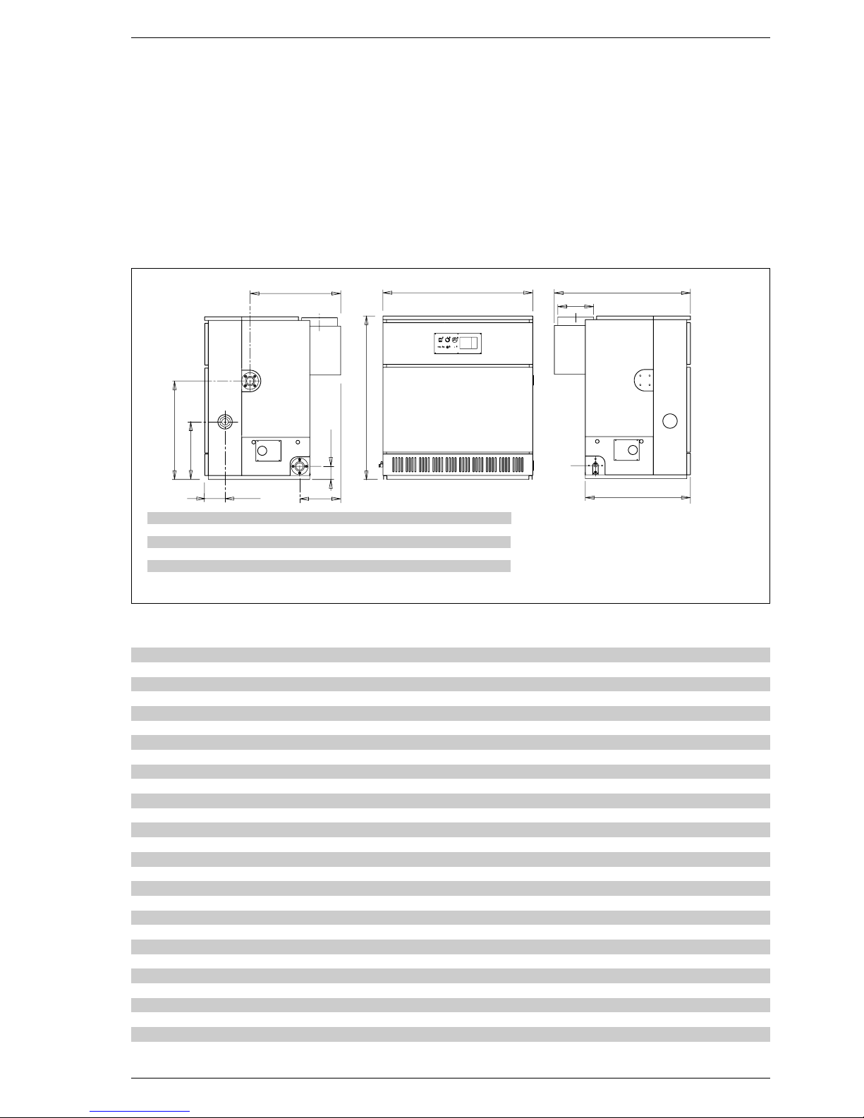
1.2 DIMENSIONS
129 151 172 194 215 237 258 279
L mm 810 920 1030 1145 1255 1370 1480 1580
P m m 1110 111 0 111 0 114 0 114 0 119 0 119 0 119 0
C mm 730 730 730 760 760 810 810 810
F mm 315 315 315 345 345 395 395 395
D ø mm 250 250 250 300 300 350 350 350
Fig. 1
R Return from heating system 2”
M Delivery to heating system 2”
G Gas 1
1
/
2
”
S Boiler drain 3/4”
1.3 TECHNICAL DATA
129 151 172 194 215 237 258 279
Thermal power kW 129,0 150,6 172,2 193,7 215,2 236,5 257,8 279,1
Thermal capacity kW 145,9 170,0 194,2 218,2 242,1 266,0 290,0 313,6
Electric power absorbed W 50 50 808080808080
Degree of electrical insulation IP 20 IP 20 IP 20 IP 20 IP 20 IP 20 IP 20 IP 20
Heating elements n° 7 8 9 10 11 12 13 14
Water content l 67,5 77,0 86,5 96,0 105,5 115,0 124,5 134,0
Max. operating pressure bar 5 5 5 5 5 5 5 5
Category II
2H3+ II2H3+ II2H3+ II2H3+ II2H3+ II2H3+ II2H3+ II2H3+
Type B11
B11 B11 B11 B11 B11 B11 B11
Maximum temperature °C 95 95 95 95 95 95 95 95
Main nozzles
Quantity n° 6 7 8 9 10 11 12 13
Methane gas ø mm 4,30 4,30 4,30 4,30 4,30 4,30 4,30 4,30
G30 - G31 ø mm 2,50 2,50 2,50 2,50 2,50 2,50 2,50 2,50
Gas rate of flow
Methane gas m
3
/h 15,44 17,99 20,55 23,10 25,63 28,16 30,70 33,20
Butane (G30) kg/h 11,50 13,41 15,32 17,21 19,10 20,98 22,88 24,74
Propane (G31) kg/h 11,32 13,19 15,07 16,93 18,79 20,64 22,50 24,34
Gas pressure at burners
Methane gas mbar 9,7 9,7 9,7 9,7 9,7 9,7 9,7 9,7
Butane (G30) mbar 28 28 28 28 28 28 28 28
Propane (G31) mbar 35 35 35 35 35 35 35 35
Gas supply pressure
Methane mbar 20 20 20 20 20 20 20 20
Butane (G30) mbar 30 30 30 30 30 30 30 30
Propane (G31) mbar 37 37 37 37 37 37 37 37
Weight kg 542 612 682 757 829 904 974 1044
Page 3
59
1.4 SHIPPING
“RS Mk.II” thermal units are supplied
in three separate packs:
PACK N. 1
Cast iron body strapped onto pallet,
complete with:
– n° 2 flanges with 2” collar for hea-
ting system delivery and return
– n° 1 blind flange
– n° 1 flange with 3/4” connection for
drain cock
– n° 2 combustion chamber doors
with cast iron indicator door
– n° 2 sheaths for thermostats and
thermometer
– n° 1 water distributor located in the
boiler return manifold, supplied in
two different lengths:
L = 406 mm vers. “129÷194”
L = 851 mm vers. “215÷279”.
PACK N. 2
Wooden crate containing:
– flue gas chamber to be assembled
– cardboard box containing skirt
– main burners, one for each element
in the body minus one
– burner manifold
– plastic bag containing:
•
n° 13 tornillos M5 x 8 screws for
anchoring burners to manifold
•
n° 32 self-tapping 12E x 1/2”
screws for fastening various parts
of the flue gas chamber and skirt
•
n° 4 M8x30 screws with plate, flat
washer and M8 nut for anchoring
flue gas chamber to boiler body
•
n° 1 3/4” drain cock with cap.
PAQUETE n° 3
Cardboard box containing:
– Gas assembly, comprising:
•
main gas valve with coil unit
•
gas pressure switch
•
pressure intake
•
second gas solenoid valve
– Electric control panel, consisting of:
•
BRAHMA SM 191.1 control device
•
interference filter
•
ignition and detection electrodes
•
sockets for connection with control panel
•
anchoring screws
– Control panel consisting of:
•
two-step control thermostat
•
manually reset safety thermostat
•
thermometer
•
gas pressure indicator light
•
device shutdown indicator light
•
illuminated main switch
•
anchoring screws.
6
7
4
2
3
1
5
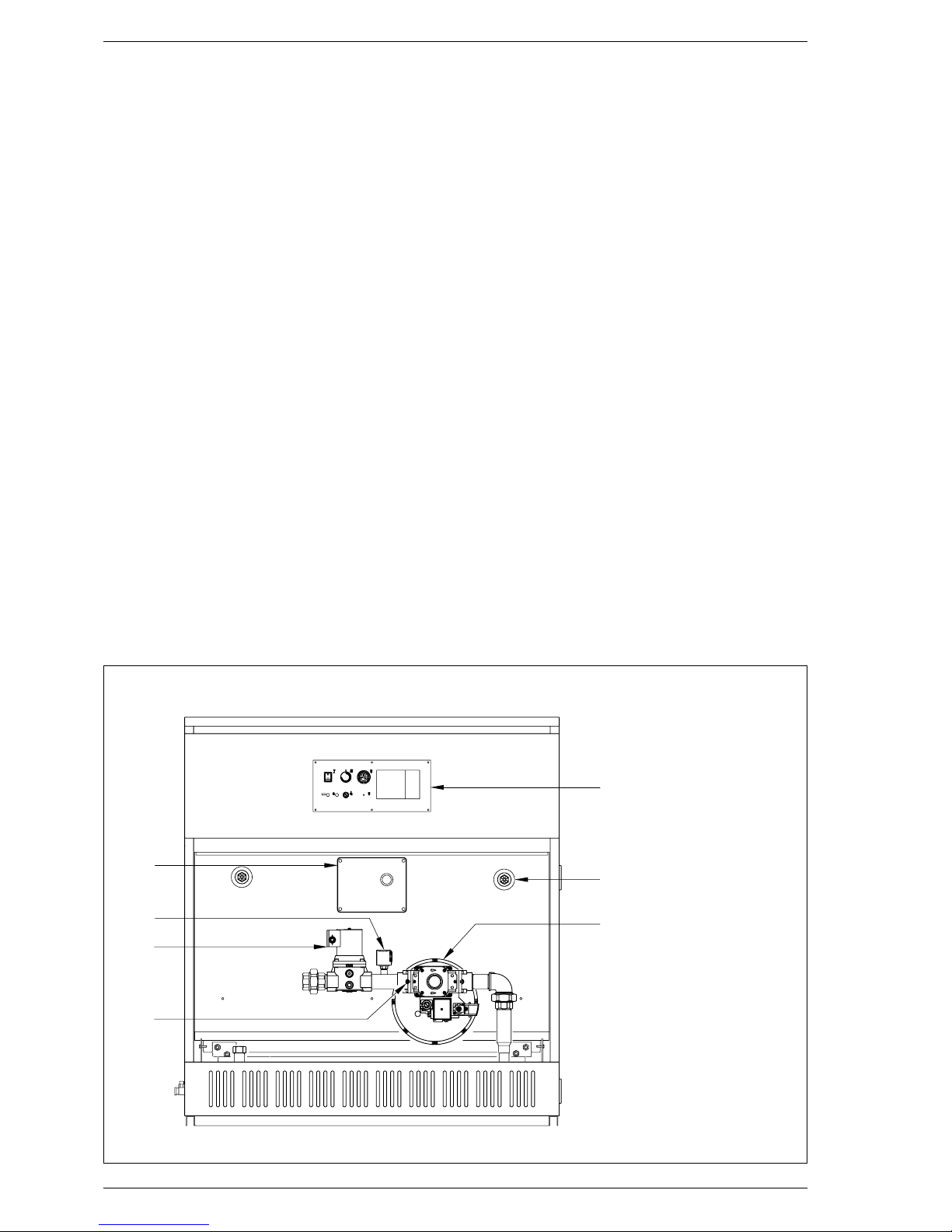
Fig. 2
1.5 FRONT INSIDE VIEW
KEY
1 Electrical control panel
2 Gas pressure switch
3 Second gas solenoid valve
4 Pressure intake
5 Control panel
6 Bulb housing sheath
7 Gas valve
Page 4

60
The boiler must be installed in a fixed
location and only by specialized and
qualified firms in compliance with all
instructions contained in this manual.
Furthermore, the installation must be
in accordance with current standards
and regulations.
2.1 BOILER ROOM
AND VENTILATION
The “RS Mk.II” boilers with a rating of
more than 35 kW must be equipped
with a technical room whose dimensions and requirements correspond to
the current safety standards. The minimum height of the boiler room must
comply with what is indicated in fig. 3 in
relation to the overall thermal capacity.
The minimum distance between the
walls of the room and the outer points
on the boiler (right and left sides and
rear) must be no less than 0.60 m. It is
possible to place a number of apparatus next to each other, on condition
that all the safety and control devices
can be easily reached. In addition, to
circulate air in the room, air vents
must be made on the outside walls for
which the surface area must never be
less than 3,000 cm
2
and 5,000 cm
2
for gas with a density greater than 0.8.
The distance between the boiler and
any fuels stored in the area must be
sufficient to prevent the fuels from reaching a hazardous temperature, and in
no case less than 4 metres.
2.2 CONNECTION WITH
HEATING SYSTEM
Connections with the heating system
should be easy to disconnect, made
with rotating pipe unions. It is always
advisable to assemble suitable gate
valves on the heating system delivery
and return pipes.
WARNING: In order to ensure proper
distribution of water in the cast iron
body, the heating system delivery
and return pipes must be connected
to the same side of the boiler. The
boiler is supplied with connections on
the right side, though they may be
moved to the left side by moving the
flanges and their collars and the corresponding water distributor.
It is advisable to ensure that the temperature dif ference between the heating system delivery and return pipes
does not exceed 20°C; installation of a
mixer valve with an anti-condensation
pump is advisable for this purpose.
WARNING: The heating system’s circulation pump(s) must be turned on
when the boiler is on. An automatic
precedence system is recommended
for this purpose.
The gas connection must be made
with seamless galvanised steel pipes
(such as Mannesmann pipes), with
threaded, sealed joints, excluding
three-piece unions except for the start
and end connections.
Pipes must pass through walls in a
sealed sheath. In determining the size
of the gas pipe from the meter to the
boiler, take into account both rate of
flow in volume (consumption) in m3/c
and the density of the gas in question.
The section of pipes in the heating
system must be sufficient to ensure
that the gas supply fulfils maximum
demand, limiting pressure drop from
the meter to any utility to no more than:
– 1,0 mbar in the case of gases in the
second family (methane gas)
– 2,0 mbar in the case of gases in the
third family (G30-G31).
On the inside of the skirt is an adhesive plate bearing technical data identifying the boiler and the type of gas
which it is set up to burn.
2.2.1 Filter on gas pipe
To prevent poor val ve functioning or, in
some cases, exclusion of the safety
devices provided, assemble an adequate filter on the gas pipe inlet.
2.3 CHARACTERISTICS
OF WATER SUPPLY
TREATMENT OF WATER USED IN THE
HEATING SYSTEM IS ABSOLUTELY
INDISPENSABLE UNDER THE FOLLOWING CONDITIONS:
– Very large heating systems (with
large water content)
– Frequent topping up of water in the
system
– When the system must be partially
or totally emptied.
2.4 FILLING THE
HEATING SYSTEM
It is a good idea to circulate water in
the pipes before connecting up the boiler in order to eliminate any foreign
matter which could affect boiler functioning. Fill the heating system slowly to
permit air bubbles to come out through
the outlets on the heating system. The
pressure at which the heating system
is filled with cold water and the preinflation pressure of the expansion tank
must correspond to, and in no case be
less than, the height of the static
column on the heating system (for
example, in the case of a static column
of 5 metres, tank pre-filling pressure
and filling pressure must at least correspond to a minimum of 0.5 bar).
2.5 FLUE
The flue for evacuation of the products
of combustion of natural draught boilers into the atmosphere must meet
the following requirements:
2 INSTALLATION
Fig. 3
H on the basis of total thermal capacity:
– no more than 116 kW: 2.00 m
– from 116 to 350 kW: 2.30 m
– from 350 to 580 kW: 2.60 m
Page 5

–
sealed against products of combustion, waterproof and heat insulated;
– made of materials which can resist
normal mechanical stress, heat and
the action of products of combustion and condensation produced by
them over time;
– ver tically oriented and free of
choking throughout its length;
– adequately insulated to prevent con-
densation or cooling of flue gases,
especially if located outside the building or in unheated premises;
– separated from combustible or
highly flammable materials by an air
space or appropriate insulation;
– provided with a chamber at least
500 mm high for collection of solid
materials and condensation underneath the entrance to the first
channel.
This chamber must be accessible
through an opening with a metal
door which does not let air in;
– circular, square or rectangular inter-
nal section; if square or rectangular,
corners must be rounded off with a
radium of no less than 20 mm;
hydraulically equivalent sections are
also permitted;
– fitted with a chimneypot at its top,
the outlet of which must be outside
of the so-called reflux area to prevent formation of counter-pressure
preventing the products of combustion from being freely released into
the atmosphere.
The minimum heights shown in fig. 4
must be complied with;
– without mechanical intake devices
at the top of the flue;
– if the flue passes through or adja-
cent to inhabited rooms, there must
be no over-pressure.
2.5.1 Flue size
The correct sizing of the flue is an
essential condition for efficient boiler
operation.
The main factors to be taken into consideration for calculating the section
are the heat input of the boiler, the type
of fuel, the percentage of CO
2
, the
mass flow of smoke at nominal load,
the temperature of the smoke, the roughness of the internal wall, and the
effect of gravity on the draught pressure, which must take into account the
external temperature and the altitude.
Table 1 shows specific parameters
pertaining to “RS Mk.II” boilers.
2.6 BOILER BODY
The cast iron body is supplied ready
assembled; if it cannot enter the boiler
room assembled, it may be supplied
dismantled.
Follow the instructions below to
assemble the body:
61
Tetto piano
0,50 m
0,50 m
Volume
tecnico
> 5 m
≤ 5m
Colmo
> 1,50 m
≤ 1,50 m
Zona di reflusso
1,50 m
2 m min.
0,50 m
oltre il colmo
45°
Tetto a 45°
Colmo
> 1,30 m
≤ 1,30 m
Zona di reflusso
0,80 m
1,20 m min.
0,50 m
oltre il colmo
30°
Tetto a 30 °
Fig. 4
TABLE 1
Thermal capacity Flue gas temperature Flue gas rate of flow
kW °C gr/s
RS 129 Mk.II 145,9 154 109,4
RS 151 Mk.II 170,0 170 111,7
RS 172 Mk.II 194,2 173 118,6
RS 194 Mk.II 218,2 153 160,8
RS 215 Mk.II 242,1 160 164,2
RS 237 Mk.II 266,0 143 206,9
RS 258 Mk.II 290,0 148 213,6
RS 279 Mk.II 313,6 154 212,5
Flat roof
30° roof
45° roof
Page 6

62
– Prepare components by cleaning
the housings of the conical nipples
with thinner.
– Introduce the plaster seam into the
groove provided for the flue gas
seal, pressing gently (fig. 5).
–
Prepare one of the two intermediate
heating elements with a 1/2” perforated stud, lubricating the conical nipples with boiled linseed oil before
introducing them (fig. 5/a).
– Prepare the head, following the same
procedure, and bring it into position
adjacent to the intermediate element.
Add only one element at a time.
– Assemble the heating elements
using the pair of tie rods supplied
assembled with their accessories,
code 6050900 (fig. 6), exerting
pressure on the upper hub and on
the lower hub simultaneously. In the
event that the elements should not
move forward in parallel during this
operation, introduce the chisel into
the tighter part and force the two
parts to be joined into parallel. The
two elements are properly joined
when their outer edges come into
contact.
– Introduce the plaster seam into the
groove in the element just mounted
and proceed to join the other elements until the body is complete.
NOTE: Before making the connection
with the heating system, test the cast
iron body at a pressure of 7.5 bar.
2.7 ASSEMBLING THE FLUE
GAS CHAMBER
The flue gas chamber is supplied in
four pieces to be joined with screws
supplied (fig. 7). It is assembled by
anchoring the right side panel (2) to
the upper panel (1) with nine self-tapping TE 12E x 1/2” screws.
The same operation must be performed on the left side panel (3). Lastly,
anchor the cleaning panel in place (4).
When assembly is complete, position
the flue gas chamber above the cast
iron body. Anchor the flue gas chamber to the body using the four plates
and the four TE M8 x 30 screws supplied (fig. 7/a).
2.8 ASSEMBLING THE WATER
DISTRIBUTOR
The water distributor on the return
line coming in from the heating
system is located on the right side of
Fig. 5
Fig. 5/a
KEY
1 Plug
2 Flange ø 35/87
3 Two-way cone
4 Tie rod L. 900 + tie rod L. 980
5 Flange ø 50/87
6 Pipe segment
7 Thrust bearing
8 Nut
9 Tightening key
Fig. 6
KEY
1 Upper panel
2 Right side panel
3 Left side panel
4 Cleaning panel
Fig. 7
Fig. 7/a
KEY
1 TE M8 x 30 screw
2 Plate
3 Washer ø 8,4
4 Nut M8
Page 7

63
the generator. If it is necessary to
move it to the left side, check that the
two rows of holes in the distributor
are directed upwards and toward the
front of the boiler (fig. 8).
2.9 ASSEMBLING THE BURNER
MANIFOLD
To assemble the burner manifold,
screw in the four TE M8 x 16 screws
on the threaded nibs of the two heads
of the boiler body (fig. 9).
2.10 ASSEMBLING THE BURNERS
Once the burner manifold has been
assembled, insert the burners in the
combustion chamber one at a time,
ensuring that the slits in the burner
are turned upward.
Push so that the burner suppor t goes
into the hole in the cast iron wall and
divides the elements (fig. 10). Anchor
the burner to the manifold with a TCB
M5 x 8 screw.
2.11 ASSEMBLING THE SKIRT
Proceed as follows to assemble the
skirt (fig. 11):
– Position the front and back supports
of the skirt base (1) between the
feet on the two heads.
– Anchor the side supports (2) and (3)
to the front and back of the skirt
base (1) with the M6 nuts supplied.
– Anchor panel (4) to panel (5) and
panel (7) to panel (8) using the connecting pins.
– and panels (7-8) to panel (9) using
connecting pins, anchoring them
together with two 7SP x 1/2” selftapping screws.
– Assemble panels (4) and (6) on the
base (3) , anchoring them on connecting pins. Proceed in the same
way to anchor panels (7) and (9) to
the base (2).
Fig. 10
KEY
1 Boiler body
2 Burner
3 Burner manifold
4 TCB M5 x 8
screw
5 Aluminium
washer ø 14
6 Burner nozzle
KEY
1 Boiler body
2 M12 x 60 stud bolt
3 Seal ø 65/95 x 2
4 Distributor pipe
5 DN50 2” collar flange
6 Nut M12
Fig. 8
Fig. 9
KEY
1 Front and rear skirt base support
2 Right skirt base support
3 Left skirt base support
4 Lower left side rear panel
5 Upper right side rear panel
6 Front left side panel
7 Rear lower right side panel
8 Rear upper right side panel
9 Front right side panel
10 Cover
11 Lower front wall
12 Upper front wall (cleaning plate)
13 Rear wall
14 Baseboard
15 Door
16 Upper front panel
Fig. 11
NOTE: The position of rings (6) and (9) may be inverted, though the
ring with the slit must always be positioned on the side where the gas
assembly exits.
KEY
1 Burner manifold
2 TE M8 x 16 screws
3 Right head
Page 8

64
– Position the lower front wall (11) by
fitting it in between the screws on
the burner manifold support
brackets and the cast iron body;
anchor the walls to panels (6) and
(9) with two 7SP x 1/2” self-tapping
screws.
– Position the upper front wall (12) by
anchoring it to panels (5-8) and to
wall (11) using four 7SP x 1/2” selftapping screws.
– Anchor the rear wall (13) to panels
(4-5) and (7-8) using the eight 7SP x
1/2” self-tapping screws supplied.
– Assemble the baseboard (14),
anchoring it to panels (6) and (9)
using connecting pins.
– Proceed in the same way to anchor
the upper front panel (16) in place.
– Assemble the cover (10) and the
door (15).
2.12 ASSEMBLING THE GAS
ASSEMBLY
Connect the gas assembly to the burner manifold as shown in fig. 12. The
gas assembly may be assembled on
the right or left side of the manifold.
WARNING: in case of the gas assembly is mounted on the left side of the
manifold, remove and rotate the gas
valve of 180° to get access frontally
at the regulations.
2.13 ASSEMBLING THE CONTROL
PANEL (fig. 12/a)
Remove the control panel’s protective
cover and inser t the wiring guard on
the front upper panel, anchoring it in
place with the screws provided. Replace the cover. Proceed to assemble the
instrument panel, anchoring it in place
with the screws provided. Insert the
instrument bulbs in their sheaths: first
insert the control thermostat bulb,
pushing it in until it touches the bottom of the sheath.
WARNING: To ensure correct temperature control in the boiler, the
bulbs of the control and safety devices must be inserted in the sheath
from the side corresponding to the
heating system delivery and return
connections. If the heating system
delivery and return connections are
on the left side of the generator, the
gas assembly must also be assembled on the left side to permit this
arrangement.
2.14 ASSEMBLING THE
ELECTRICAL PANEL
(fig. 12/b)
Remove the cover of the electrical
panel and anchor the control panel to
the lower front wall using the screws
provided. Connect the two sockets to
the plugs from the control panel. Complete the electrical panel by hooking up
the gas valve, the second gas solenoid
valve, the gas pressure switch and the
coil. Unwind the cables of the ignition
and detection electrodes emerging
from the electrical panel. Insert the
ignition electrode in the hole between
the head and the intermediate on the
gas assembly side, anchoring it to the
two stud bolts (fig. 12/c).
Perform the same operation on the
detection electrode, which will go in
the hole provided between the head
and the intermediary at the other end
of the body.
1
2
3
KEY
1 Burner manifold
2 Gas assembly
3 Bulb sheath
Fig. 12
KEY
1 Protective cover
2 Wiring guard
3 Front upper panel
4 Instrument panel
5 Instrument bulbs
6 Sheath
7 5 pole plug
8 7 pole plug
Fig. 12/a
KEY
1Cover
2 Electrical panel
3 Lower front panel
4 5 pole plug
5 7 pole plug
6
Second gas solenoid valve cable
7 Gas pressure switch cable
8 Gas valve cable
9 Coil cable
10 Detection electrode
11 Ignition electrode
Fig. 12/b
Page 9

NOTE: When assembling the two
electrodes, be very careful not to
break their ceramic coating; they
must be replaced immediately if it
is broken. All gas connections
must be tested for seal after
assembly using soapy water or
products manufactured specifically for the purpose, without using
open flame.
2.15 ELECTRICAL CONNECTION
The electrical power supply must be
connected to terminals L and N and
to the panel complying with all phase
and neutral positions as shown in
the diagram. If they are not connected properly, the flame detection circuit will not work and the boiler will
be shut down. The boiler must be con-
nected up to a single phase 230V50Hz power supply through a main
switch protected by fuses with at least
3 mm between contacts (fig. 13).
NOTE: The device must be connected to an efficient grounding
system. SIME shall not accept any
liability for damage or injury resulting from failure to ground the boiler. Turn off the power supply before
performing any operations on the
electrical panel.
65
KEY
SB Boiler shutdown indicator light
PG Gas pressure switch
EVG Main gas valve
F T 4 fuse
ER Detection electrode
E Ignition electrode
TC Step control thermostat
IG Main switch
SG Gas pressure indicator light
TS Safety thermostat
A SM 191.1 device
P Water pressure switch (not supplied)
B Coil
EVS Second gas solenoid valve
F Interference filter
TF Flue gas thermometer (Poland only)
UA Type Q 70 room thermometer (optional)
SE Outdoor temperature probe (optional)
SC Type Q Z21 boiler immersion probe (optional)
SS Type Q Z21 boiler immersion probe (optional)
PI Heating system pump (not supplied)
PB Boiler pump (not supplied)
C Control unit connectors (black - red - brown)
T Climate control
TI Insulation transformer (Belgium only)
F1 Fuse F800 mA (Belgium only)
SF Flue gas gate (not supplied)
NOTE: When connecting up the RVA 43.222 unit,
remove jumpers 12 - 13 and 15 - 16. When connecting up the flue gas gate (SF) remove the jumper
between terminals 22 - 23.
Fig. 13
KEY
1 Ignition electrode
2 M5 x 15 stud bolt
3 Washer ø 5.3
4 Nut M5 OT
5 Right head
6 Intermediate element
with nib
Fig. 12/c
Page 10

2.16 RVA43.222
CONTROL UNIT
(optional)
All boiler functions can be controlled
by the optional control unit code
8096303, supplied with an outdoor
temperature probe (SE) and boiler
immersion probe (SC) (fig. 14). Use of
the control unit requires connection of
an additional series of low voltage connectors for connection of probes and
the room temperature control unit
(the connectors are supplied in a bag
in the control panel). The bulb of the
sensor of the external D.H.W. tank
(SS), optional code 6277110, must
be inserted in the hot water sheath
and the boiler probe (SC) in the boiler
sheath. To assemble the outdoor temperature probe (SE), follow the instructions provided on its packaging. Refer
to the wiring diagram in fig. 13 for
electrical connections.
WARNING: to grant the correct
operation of the plant set the boiler thermostat at the maximum
value.
2.16.1 Features and functions
“RVA 43.222” is realized as regulator
of one boiler mono or bi-stadium or
regulator of cascade connections to
manage 16 boilers maximum.
Economical operation
– Heat production may be turned on
or off in the presence of integration
with accumulation.
– Boiler temperature control on the
basis of climate, permitting environmental compensation.
– Direct heating circuit management
(with pump) for each controller.
– Automatic adaptation to climatic
curve on the basis of the building’s
thermal inertia and the presence of
“free heat” sources (with environmental compensation).
– On/off optimisation (accelerated
heating and early off feature).
– Daily economy function calculated
on the basis of the dynamic characteristics of the building.
– Automatic summer/winter switch.
Protective functions
– Minimum and maximum delivery
temperature settings.
– Differentiated anti-freeze protection
for boiler, hot water tank and heating system.
– Boiler overheating protection.
– Pump seizing up protection.
– Burner protection with minimum
operating temperature.
Operative functions
– Simplified start-up.
– All calibration operations are per for-
med on control unit.
– Standard weekly programming.
– All calibration operations and opera-
ting settings can be read on leds
and display.
– Relay and probe tests.
Hot water production
– Daily scheduling.
–
Minimum hot water delivery temperatu-
re may be set for reduced time period.
–
Control of hot water tank filling pump.
–
Selectable priority of hot water circuit.
Other technical features
– Easy connection with digital environ-
mental unit (QAA 70).
2.16.2 Electrical connection
The electrical circuit includes a series
of connectors for installation of an
optional control unit, marked with dif ferent colours: black, red and brown (fig.
14/a). Connectors are polarised so
that order cannot be inverted.
To install the control unit, connect these
connectors and remove jumpers 13 14 and 16 - 17 from the terminal board
(fig. 13). The control unit also permits
use of room temperature control units
and probes; polarised, coloured connectors for these are located in a bag inside the control panel.
66
12
Fig. 14
KEY
1 Plastic hole cover
2 Optional control unit
12 3
Fig. 14/a
KEY
1 Control unit connectors (black - red - brown)
2 Fuse (T 4 )
3 Terminal boar d
 Loading...