

Powrmatic PZN 12, PZN 13, PZN 22, PZN 23, PZN 32 User, Installation & Servicing Instructions
...Page 1
www.powrmatic.co.uk
®
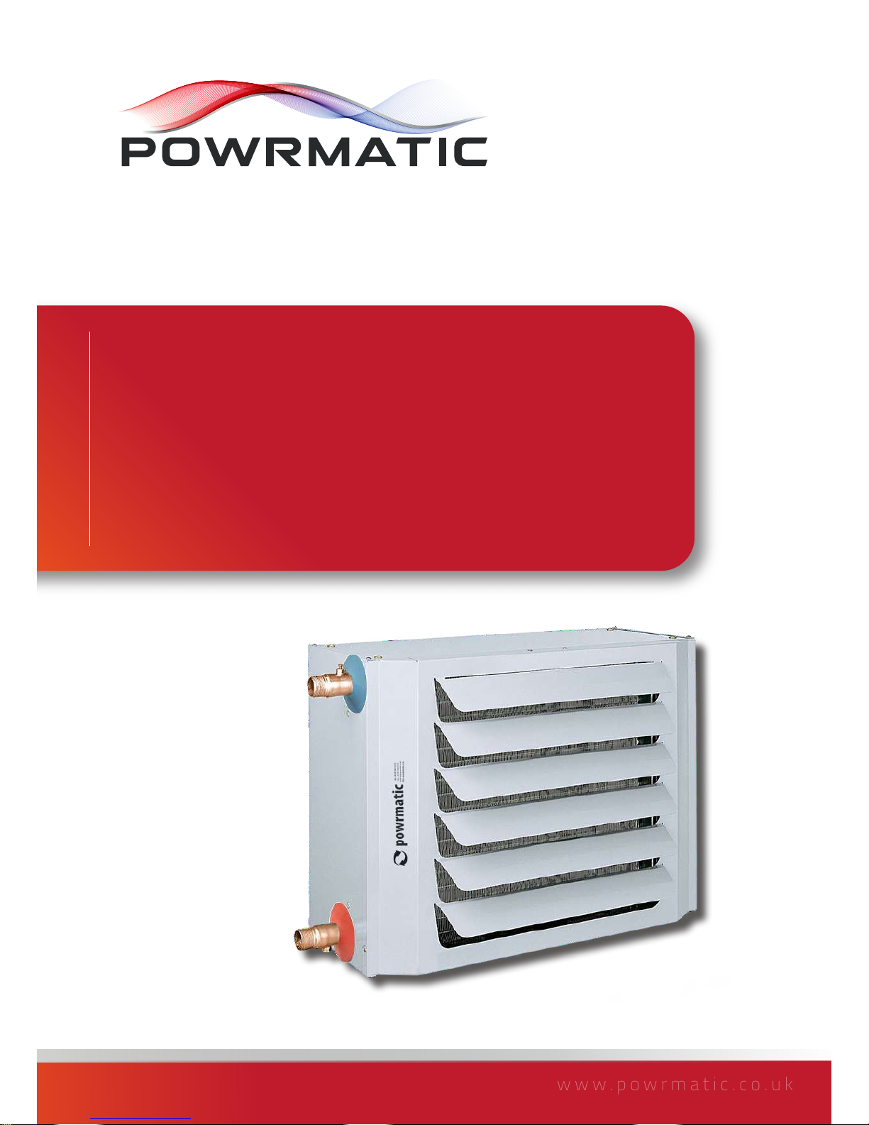
PZN
User, Installation & Servicing Manual
Issue 1.3 September 2018
Doc Ref: M107 Issue 1.3 Sep 2018
Page 2

page no. 2 oF 28
PZN Aquamatic Water Heater Doc Ref M107 issue 1.3 Sep 2018.
Important: This certificate
must be kept with the appliance
Failure to provide a copy of the commissioning sheet invalidates the heater warranty
----------------------------------------------------
Powrmatic Ltd, Hort Bridge, Ilminster, Somerset, TA19 9PS
Tel: 01460 53535 Fax: 01460 52341
Web: www.powrmatic.co.uk e-mail: [email protected]
This is to certify that this appliance is guaranteed for 12 months parts only from the date of original
commissioning. The heater must be commissioned within 4 weeks of installation.
To make a claim
In the first instance you must contact your appliance supplier, or installer and provide:-
1. The appliance type and serial number.
2. The original commissioning documentation. As much detail as possible on the fault.
3. Your supplier, or installer, will then contact Powrmatic to make a guarantee claim on your behalf.
Conditions of Guarantee
1. The heater must have been installed by a competent qualified installer, and in accordance with
the manufacturer’s instructions, building regulations and local regulations.
2. The heater has been professionally commissioned, within 4 weeks of installation, and a copy of
the commissioning sheet returned to Powrmatic.
3. The heater has been maintained on a yearly basis by a competent and qualified servicing
company.
4. The heater has been used in accordance with the manufacturer’s instructions.
5. The correct specification fuel has been used.
6. No unauthorised repairs of modifications have been made. Powrmatic ‘General Conditions of
Sales’ have been observed.
7. Except for the obligation of Powrmatic Ltd to perform warranty repairs during the guarantee
period, Powrmatic will not be liable in respect of any claim for direct or indirect consequential
losses, including loss of profits or increased cost arising from loss of use of the heater, or any
event arising there from.
Exclusions
Consumables such as links, control batteries are all excluded from guarantee.
®
Page 3
page no. 3 of 28
PZN Aquamatic Water Heater Doc Ref M107 issue 1.3 Sep 2018.
Title Section Contents Page
User Instructions 4
Pre Installation
1.1 Introduction 4
Duties 6
Dimensions 7
1.2 Technical data 8
1.3 General Requirements 16
Installation
2.1 Fitting the unit 19
2.2 Electrical Cable Installation 21
2.3 Wiring Diagrams 22
2.4 Commissioning and Testing 24
2.5 Servicing 25
Additional Documents
3.1 Fault Finding 27
Page 4
page no. 4 oF 28
PZN Aquamatic Water Heater Doc Ref M107 issue 1.3 Sep 2018.
To maintain efficient, reliable and safe operation of the
heater it must serviced annually by a qualified person.
This manual is an integral part of the machine, therefore
it should always be kept safe and it should always be
provided together with the machine, if it is transferred to
another owner or user. In case of damage or loss of this
booklet, request another copy from your local Technical
Assistance Service or Manufacturer.
Free access must be maintained to and around the heater
for servicing purposes and the air supply to the heater
must not be restricted in any way. Combustible materials
must not be stored adjacent to the heater.
Ensure that any air inlet or outlet louvres of the unit are
not blocked or restricted in anyway as this may lead to the
unit malfunctioning.
All Powrmatic units use electricity to power them, they
may also contain moving parts. It would be hazardous
to tamper with or attempt to service unless you are a
competent person in the field of Electrical work.
If you have any safety questions reference the servicing
and installation of any of our heaters please do not
hesitate to contact our head office for expert advice. Your
safety is paramount to us.
Excess temperature is damaging to health and represents
a waste of energy. Do not leave the rooms closed for a
long time. Periodically open a window to air the room/
building.
If you do not intend to use the unit for a long period of
time you MUST at least do the following:
• turn the main switch of the unit and the general
switch of the plant to "OFF"
• close the water check valves;
• if there is a risk of sub-zero temperatures, drain the
water from the unit.
If the unit has remained idle for a long period it is advisable
to have it restarted by an authorised Technical Assistance
Service or, in any case, by professionally qualified
personnel.
In case of water leaks, turn the main switch "off" and
close the water taps. Immediately call the Technical
Assistance Service or professionally qualified personnel
and do not intervene personally on the unit.
The manufacturer is responsible for the product
compliance with Laws, Directives or Construction Rules in
If the heater has not been left operational
proceed as follows.
The following preliminary checks should be made before
operating the unit
a) Ensure that the ELECTRICAL supply to the unit is
switched OFF.
b) The unit is positioned correctly.
c) Water and electrical connections have been made
correctly.
d) Water pressure (unit cold) is as required.
e) Any air has been bled from the system.
g) Check that any delivery outlet grilles are open.
h) Check that the external thermostat is set. (if fitted)
j) Check that the clock control is set to ON. (if fitted)
k) Check that any controls are switched on. (if fitted)
l) Ensure boiler is operational and check valves are open.
• Switch on the electrical supply at the isolator.
• Position the main switch to ON.
• Set fan speed as desired (where speed selector
switch is installed).
• Set room thermostat to desired temperature (higher
than current room temperature).
• At this point both the water circulator and the
heater fan start simultaneously. To prevent an initial
outflow of unpleasant cold air it is possible to delay
fan start-up with the aid of a minimum thermostat
(not supplied as accessory). This thermostat also
delays fan shutdown so as to disperse all the heat
accumulated in the exchanger into the room/area to
be heated.
• Once the temperature set on the room thermostat
has been reached the heater will shut down. When
the temperature drops back down below this setting
the fan heater restarts automatically.
1) For Short Periods:
Turn any controls/switches to OFF.
Turn the thermostat to the OFF (if fitted).
2) For Long Periods:
• Deactivate the fan heater by acting on the room
thermostat;
• Turn the main switch to OFF.
• Close the water check valves.
Page 5
page no. 5 of 28
PZN Aquamatic Water Heater Doc Ref M107 issue 1.3 Sep 2018.
Water-fed fan heaters are designed to provide heating in
winter and ventilation in summer.
The unit is designed to be suspended from suitable
roof points or alternatively to be mounted on purpose
designed brackets and are intended primarily for
commercial or industrial premises.
Hot water produced by the boiler/heat pump (not suppled)
flows through the high efficiency copper heat exchanger.
A high performance axial fan on the rear of the unit blows
ambient air across the warm heat exchanger, increasing
the output temperature.
The fan has the capability of running at three speeds
when used in conjunction with the optional variable speed
switch.
During the summer the fan can be run on its own to
provide ventilation.
IMPORTANT
Service and Maintenance Engineers shall
ensure that replacement items are fitted,
adjusted and set in accordance with the
data and detail set out in these instructions. If in doubt
consult Powrmatic Technical Department.
• Bear in mind that if you use products powered
trough electric power, gas, etc., you should comply
with some basic rules, such as:
• This device cannot be used by people (including
children) with reduced physical, sensory or mental
abilities or lack of experience and knowledge, unless
they are supervised or trained on the use of the unit
by the person who is responsible for its safety.
• Do not touch the heater if you are barefoot or if parts
of your body are wet .
• Before carrying out any cleaning and/or maintenance
work on the unit always disconnect the unit from the
mains power supply by turning the main switch to
OFF.
• Any modification to safety or regulation systems
is strictly forbidden without the Manufacturer’s
permission and guidance.
• Do not pull, disconnect and twist the electrical cables
coming from the unit, even if it is disconnected from
the electrical power supply.
• Do not stand or sit on the unit and/or put any objects
on the unit.
• Do not abandon or leave available to children the
heater packing materials (cartons, nails, plastic bags
etc.), as these are a potential source of danger.
• Do not install the unit in areas with a damp or
“aggressive” atmosphere.
• Do not insert foreign objects through the grille in the
cover.
• Do not touch the heat exchanger battery with naked
hands.
• Do not use adapters, multiple sockets or extension
leads to connect the unit to the electricity supply.
• It is forbidden to install the unit outdoors or where it
is exposed to adverse weather conditions.
force when the product is marketed. The knowledge and
observance of the laws and standards regarding plant
design, installation, operation and maintenance are the
sole responsibility of the designer, installer and user.
The manufacturer shall not be held responsible for
failure to comply with the instructions of this manual,
for the consequences of any operations carried out and
not specifically provided for or for translations open to
misinterpretation.
Page 6
page no. 6 oF 28
PZN Aquamatic Water Heater Doc Ref M107 issue 1.3 Sep 2018.
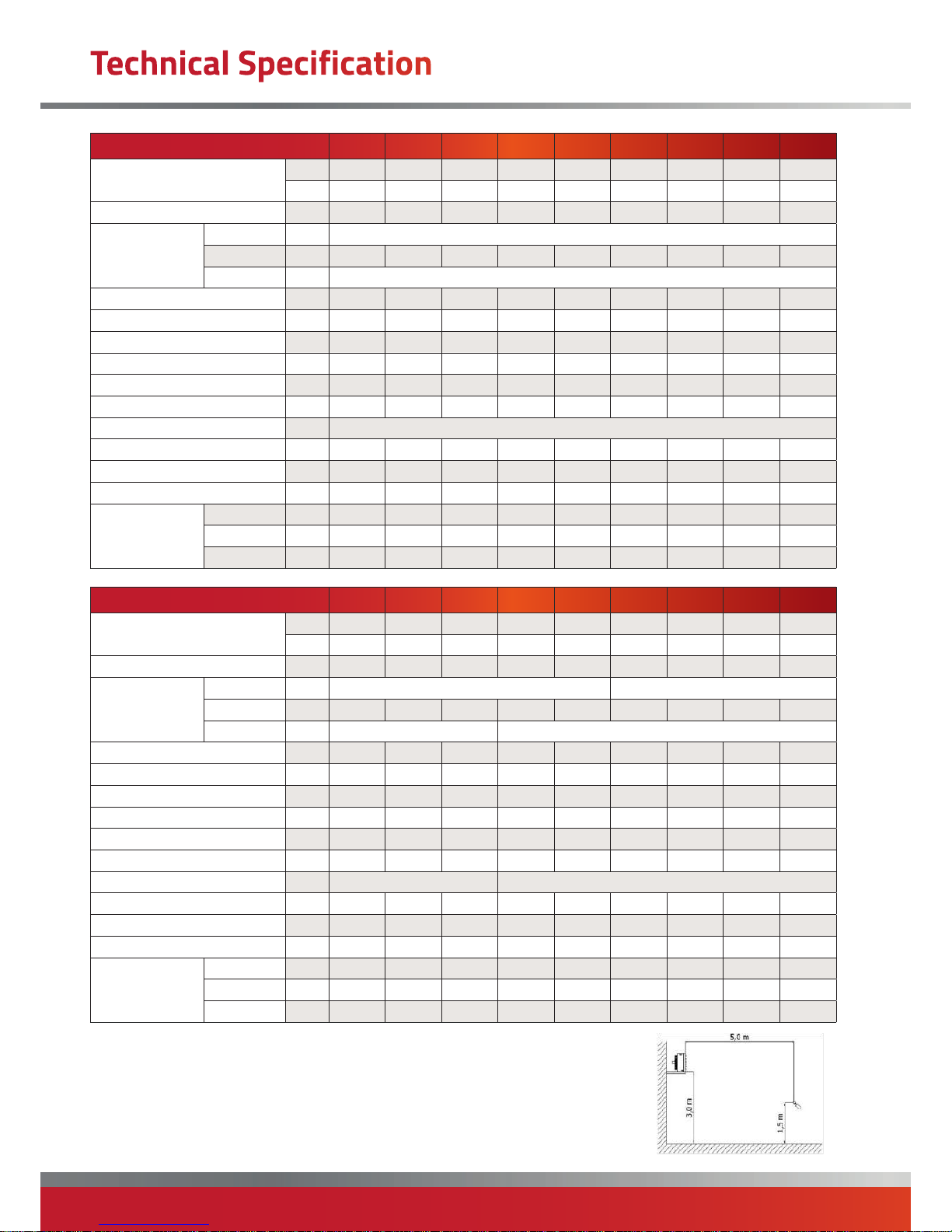
Model 12 13 22 23 32 33 42 43 52
Thermal Power ¹
kW 13.3 17.3 17.7 23.8 22.0 28.5 27.4 35.4 31.9
kcal/h 11440 14880 15220 20470 18920 24510 23560 30440 27430
Rows no. 2 3 2 3 2 3 2 3 2
Axial Fan
Qty
no. 1
dia
mm 300 300 315 315 330 330 350 350 400
rotations
rpm 1400 - 900 - 700 ³
Airflow Rate m³/h 1750 1550 2450 2300 2800 2550 3600 3400 3950
Air Delivery m 22 17 25 19 31 25 31 25 32
Air Supply Temperature ¹ °C 38 47 36 45 38 47 37 46 39
deltaP Water Side kPa 26 20 17 20 30 17 24 19 20
Water Flow Rate l/h 785 1020 1044 1401 1296 1680 1612 2141 1876
Water Capacity l 1.2 1.6 1.5 2.1 1.9 2.5 2.2 3.0 2.6
Electrical Supply V/ph/Hz 230V/1Pha/50Hz
Degree of Protection IP 55 55 55
55 54 54 54 54 55
Total Electrical Supply V/ph/Hz 74 74 86 86 120 120 130 130 200
Max Electrical Current V/ph/Hz 0.34 0.34 0.38 0.38 0.55 0.55 0.60 0.60 0.60
Sound Power Level ²
Max
dB 50 50 51 51 52 52 53 53 53
Med
dB 47 47 47 47 50 50 49 49 49
Min
dB 41 41 45 45 43 43 43 43 43
Model 53 62 63 72 73 82 83 92 93
Thermal Power ¹
kW 42.7 39.1 52.4 47.4 63.0 67.7 87.8 88.8 114.9
kcal/h 36720 33630 45060 47760 54180 58220 75510 76370 98810
Rows no. 3 2 3 2 3 2 3 2 3
Axial Fan
Qty
no. 1 2
dia
mm 400 420 420 550 550 450 450 550 550
rotations
rpm 1400 - 900 - 700 ³ 900 - 700 ³
Airflow Rate m³/h 3900 5200 4900 6700 6200 8500 7700 12550 10900
Air Delivery m 24 33 26 39 37 38 32 40 38
Air Supply Temperature ¹ °C 47 37 26 39 37 38 32 40 38
deltaP Water Side kPa 13 13 16 14 12 11 9 21 17
Water Flow Rate l/h 2514 2300 3086 2793 3707 3985 5173 5229 6764
Water Capacity l 3.6 3.0 4.6 3.5 5.2 5.3 7.3 6.1 8.5
Electrical Supply V/ph/Hz 230V/1Pha/50Hz 400V/3Pha/50Hz
Degree of Protection IP
55 55 55 55 55 55 55 55 55
Total Electrical Supply V/ph/Hz 200 220 220 305 305 240 240 610 610
Max Electrical Current V/ph/Hz 0.90 0.95 0.95 0.70 0.70 0.56 0.56 1.40 1.40
Sound Power Level ²
Max
dB 53 53 53 52 52 54 54 53 53
Med
dB 49 49 49 - - - - - -
Min
dB 43 47 47 46 46 49 49 48 48
(1) Data refers to following conditions:
- Water temperature 85-70°C
- Air temperature 15°C
- R.H. 50%
- Atmospheric pressure 1013 mbar
- Max fan speed
(2) Data refers to following conditions:
- Area unobstructed
- Max fan speed
Unit installed on wall 3 m above ground with
sound pressure measured frontally.
(3) RPM variations attained via use of
special accessories (available as optionals).
RPM figures are average values as RPM
varies from model to model.
Page 7
page no. 7 of 28
PZN Aquamatic Water Heater Doc Ref M107 issue 1.3 Sep 2018.
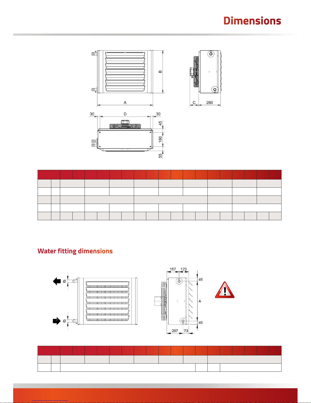
Model 12 13 22 23 32 33 42 43 52 53 62 63 72 73 82 83 92 93
A mm 555 605 655 705 755 805 855 1205 1405
B mm 390 440 490 540 590 640 690 690 690
C mm 90 116 122 172 162 172
D mm 489 539 589 639 689 739 789 1139
Weight kg 14 15 16 18 19 21 23 24 25 28 29 32 40 43 58 63 70 76
Model 12 13 22 23 32 33 42 43 52 53 62 63 72 73 82 83 92 93
A mm 300 350 400 450 500 550 600
Ø male in 1 1¼ 1 1¼
Warning: For
optimum
performance it is
essential that water
inlet-outlet directions always be
observed as indicated by the
adhesive label.
Page 8
page no. 8 oF 28
PZN Aquamatic Water Heater Doc Ref M107 issue 1.3 Sep 2018.
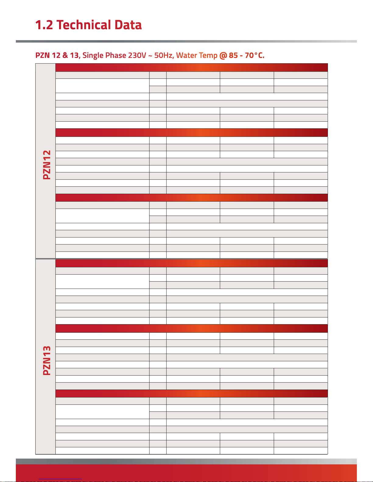
Fan heater at MAXIMUM fan speed.
Airflow Rate °C 15 20 25
Thermal Power
kW 11 12.2 11
Kcal/h 11450 10450 9450
Air Flow Rate m³/h 1750
Sound Pressure Level dB(A) 50
Air Outlet Temperature °C 38 41 44
Water Side Heat Loss kPa 26 22 18
Water Flow Rate l/h 785 715 647
Fan heater at MEDIUM fan speed.
Airflow Rate °C 15 20 25
Thermal Power kW 11.6 10.6 9.6
Kcal/h 10000 9150 8250
Air Flow Rate m³/h 1250
Sound Pressure Level dB(A) 47
Air Outlet Temperature °C 43 46 49
Water Side Heat Loss kPa 20 17 15
Water Flow Rate l/h 685 625 566
Fan heater at MINUMUM fan speed.
Airflow Rate °C 15 20 25
Thermal Power
kW 10.2 9.3 8.4
Kcal/h 8750 8000 7200
Air Flow Rate m³/h 900
Sound Pressure Level dB(A) 41
Air Outlet Temperature °C 48 50 53
Water Side Heat Loss kPa 16 14 11
Water Flow Rate l/h 598 546 494
Fan heater at MAXIMUM fan speed.
Airflow Rate °C 15 20 25
Thermal Power
kW 17.3 15.8 14.3
Kcal/h 14900 13600 12300
Air Flow Rate m³/h 1550
Sound Pressure Level dB(A) 50
Air Outlet Temperature °C 47 50 53
Water Side Heat Loss kPa 20 17 14
Water Flow Rate l/h 1020 931 842
Fan heater at MEDIUM fan speed.
Airflow Rate °C 15 20 25
Thermal Power kW 14.9 13.5 12.3
Kcal/h 12800 11650 10550
Air Flow Rate m³/h 1150
Sound Pressure Level dB(A) 47
Air Outlet Temperature °C 53 55 58
Water Side Heat Loss kPa 15 13 11
Water Flow Rate l/h 875 798 722
Fan heater at MINUMUM fan speed.
Airflow Rate °C 15 20 25
Thermal Power
kW 12.6 11.5 10.3
Kcal/h 10800 9850 8900
Air Flow Rate m³/h 850
Sound Pressure Level dB(A) 41
Air Outlet Temperature °C 59 61 62
Water Side Heat Loss kPa 11 10 8
Water Flow Rate l/h 741 675 611
Page 9
page no. 9 of 28
PZN Aquamatic Water Heater Doc Ref M107 issue 1.3 Sep 2018.
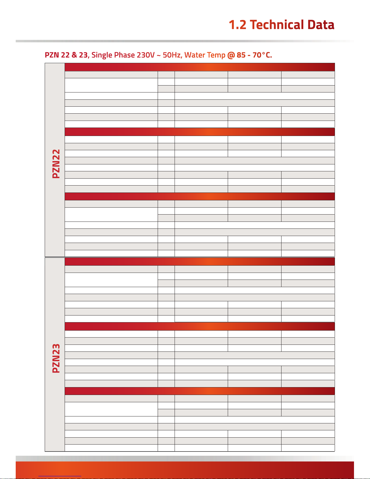
Fan heater at MAXIMUM fan speed.
Airflow Rate °C 15 20 25
Thermal Power
kW 17.7 16.2 14.7
Kcal/h 15250 13900 12600
Air Flow Rate m³/h 2450
Sound Pressure Level dB(A) 51
Air Outlet Temperature °C 36 40 43
Water Side Heat Loss kPa 17 15 12
Water Flow Rate l/h
1044 952 861
Fan heater at MEDIUM fan speed.
Airflow Rate °C 15 20 25
Thermal Power kW 16.7 15.2 13.7
Kcal/h 14350 13100 11800
Air Flow Rate m³/h 2050
Sound Pressure Level dB(A) 47
Air Outlet Temperature °C 39 42 45
Water Side Heat Loss kPa 15 13 11
Water Flow Rate l/h 981 895 810
Fan heater at MINUMUM fan speed.
Airflow Rate °C 15 20 25
Thermal Power
kW 16.2 14.8 13.4
Kcal/h 13900 12700 11500
Air Flow Rate m³/h 1900
Sound Pressure Level dB(A) 45
Air Outlet Temperature °C 40 43 46
Water Side Heat Loss kPa 15 12 10
Water Flow Rate l/h 953 869 786
Fan heater at MAXIMUM fan speed.
Airflow Rate °C 15 20 25
Thermal Power
kW 23.8 21.7 19.7
Kcal/h 20450 18650 16900
Air Flow Rate m³/h 2300
Sound Pressure Level dB(A) 51
Air Outlet Temperature °C 45 48 51
Water Side Heat Loss kPa 20 17 14
Water Flow Rate l/h
1401 1278 1156
Fan heater at MEDIUM fan speed.
Airflow Rate °C 15 20 25
Thermal Power kW 21.6 19.7 17.8
Kcal/h 18600 16950 15350
Air Flow Rate m³/h 1850
Sound Pressure Level dB(A) 47
Air Outlet Temperature °C 49 52 54
Water Side Heat Loss kPa 19 14 12
Water Flow Rate l/h 1271 1159 1049
Fan heater at MINUMUM fan speed.
Airflow Rate °C 15 20 25
Thermal Power
kW 19.8 18.1 16.3
Kcal/h 17050 15550 14050
Air Flow Rate m³/h 1550
Sound Pressure Level dB(A) 45
Air Outlet Temperature °C 52 55 57
Water Side Heat Loss kPa 14 12 10
Water Flow Rate l/h 1168 1065 963
Page 10
page no. 10 oF 28
PZN Aquamatic Water Heater Doc Ref M107 issue 1.3 Sep 2018.
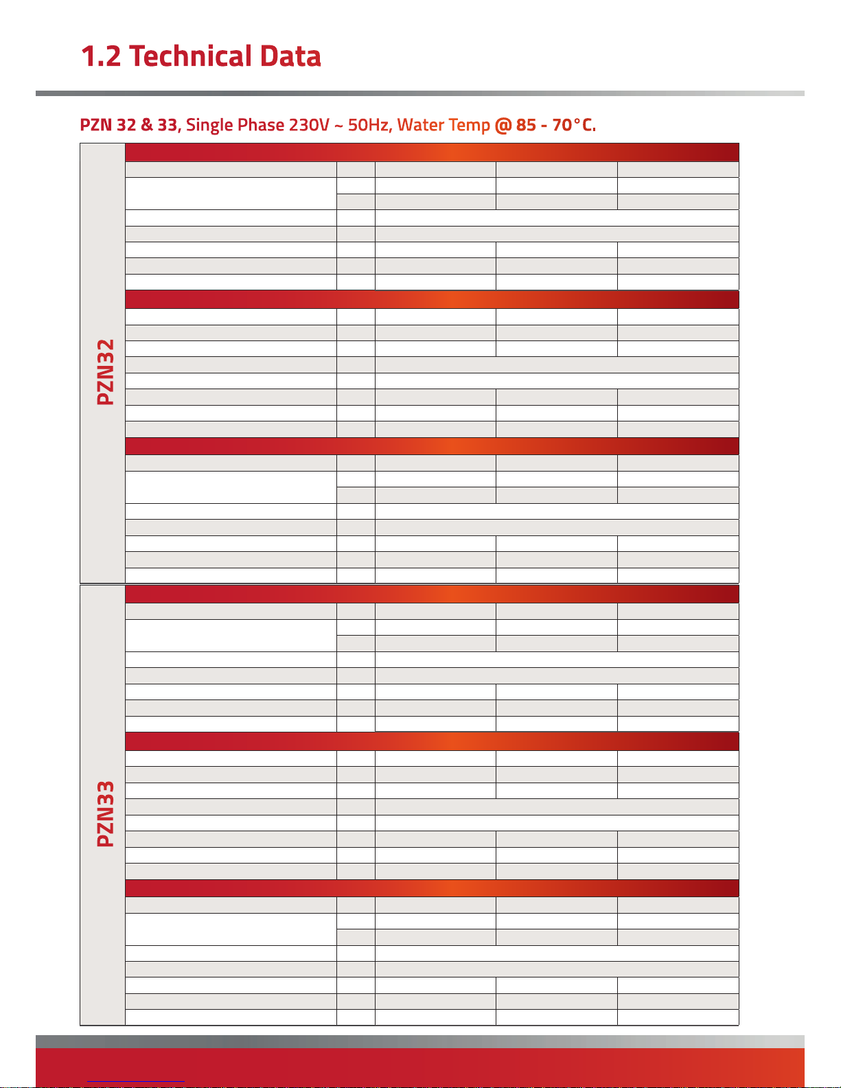
Fan heater at MAXIMUM fan speed.
Airflow Rate °C 15 20 25
Thermal Power
kW 22.0 20.1 18.2
Kcal/h 18950 17300 15650
Air Flow Rate m³/h 2800
Sound Pressure Level dB(A) 52
Air Outlet Temperature °C 38 41 45
Water Side Heat Loss kPa 30 26 22
Water Flow Rate l/h
1296 1184 1072
Fan heater at MEDIUM fan speed.
Airflow Rate °C 15 20 25
Thermal Power kW 19.4 17.7 16.0
Kcal/h 16700 15250 13750
Air Flow Rate m³/h 2050
Sound Pressure Level dB(A) 50
Air Outlet Temperature °C 43 46 49
Water Side Heat Loss kPa 24 21 17
Water Flow Rate l/h 1142 1043 944
Fan heater at MINUMUM fan speed.
Airflow Rate °C 15 20 25
Thermal Power
kW 17.5 16.0 14.5
Kcal/h 15050 13750 12450
Air Flow Rate m³/h 1650
Sound Pressure Level dB(A) 43
Air Outlet Temperature °C 46 49 52
Water Side Heat Loss kPa 20 17 14
Water Flow Rate l/h 1031 941 85215
Fan heater at MAXIMUM fan speed.
Airflow Rate °C 15 20 25
Thermal Power
kW 28.5 26.0 23.5
Kcal/h 24550 22400 20250
Air Flow Rate m³/h 2550
Sound Pressure Level dB(A) 52
Air Outlet Temperature °C 47 50 53
Water Side Heat Loss kPa 17 15 13
Water Flow Rate l/h
1680 1532 1386
Fan heater at MEDIUM fan speed.
Airflow Rate °C 15 20 25
Thermal Power kW 25.4 22.4 20.2
Kcal/h 21100 19250 17400
Air Flow Rate m³/h 1900
Sound Pressure Level dB(A) 50
Air Outlet Temperature °C 53 55 58
Water Side Heat Loss kPa 13 11 10
Water Flow Rate l/h 1446 1318 1192
Fan heater at MINUMUM fan speed.
Airflow Rate °C 15 20 25
Thermal Power
kW 21.3 19.4 17.6
Kcal/h 18350 16700 15100
Air Flow Rate m³/h 1450
Sound Pressure Level dB(A) 43
Air Outlet Temperature °C 58 60 62
Water Side Heat Loss kPa 11 9 7
Water Flow Rate l/h 1255 1144 1035
Page 11
page no. 11 of 28
PZN Aquamatic Water Heater Doc Ref M107 issue 1.3 Sep 2018.
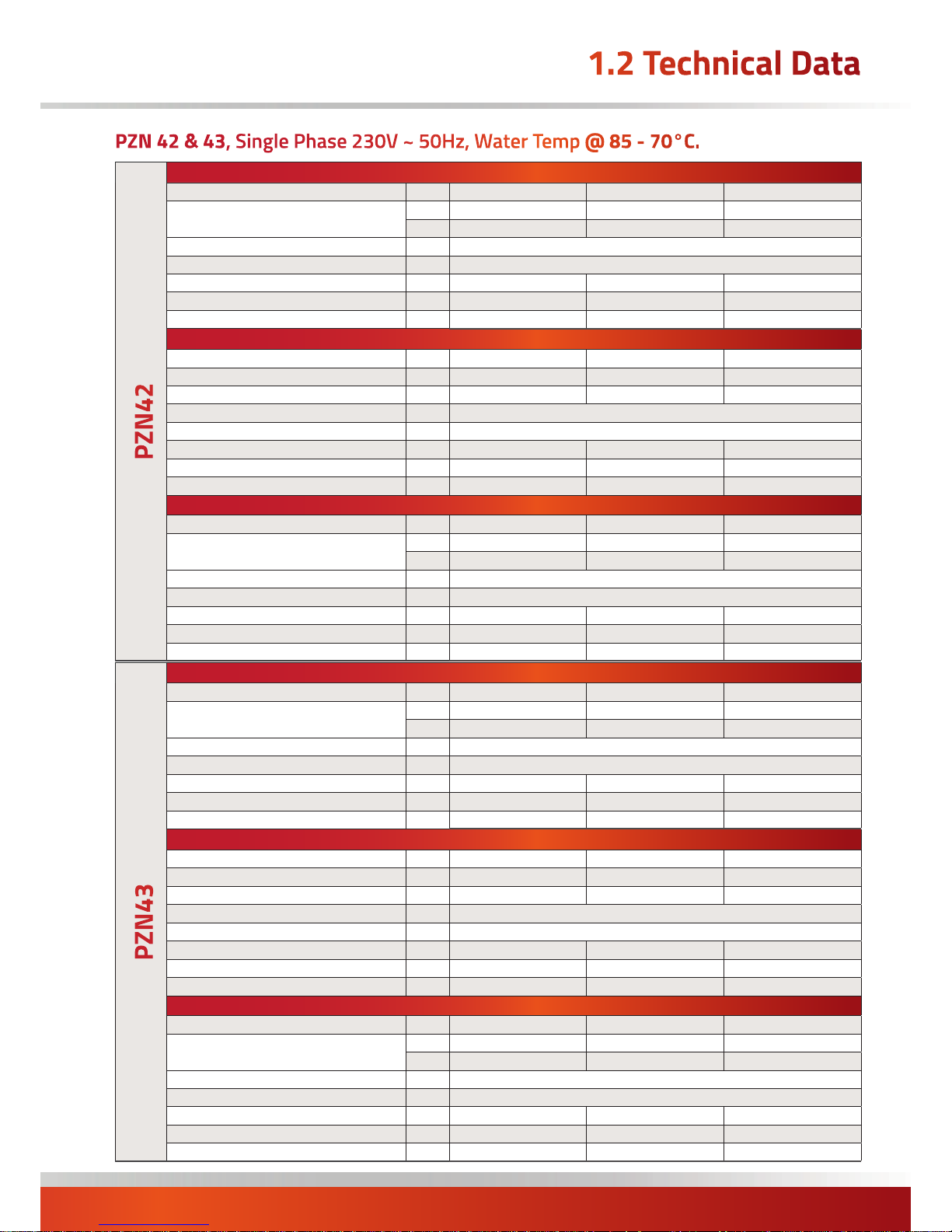
Fan heater at MAXIMUM fan speed.
Airflow Rate °C 15 20 25
Thermal Power
kW 27.4 25.0 22.6
Kcal/h 23550 21500 19450
Air Flow Rate m³/h 3600
Sound Pressure Level dB(A) 53
Air Outlet Temperature °C 37 41 44
Water Side Heat Loss kPa 24 20 17
Water Flow Rate l/h
1612 1471 1332
Fan heater at MEDIUM fan speed.
Airflow Rate °C 15 20 25
Thermal Power kW 23.0 21.0 19.0
Kcal/h 19800 18050 16350
Air Flow Rate m³/h 2350
Sound Pressure Level dB(A) 49
Air Outlet Temperature °C 44 47 50
Water Side Heat Loss kPa 18 15 13
Water Flow Rate l/h 1355 1237 1119
Fan heater at MINUMUM fan speed.
Airflow Rate °C 15 20 25
Thermal Power
kW 19.7 18.0 16.3
Kcal/h 16950 15450 14000
Air Flow Rate m³/h 1650
Sound Pressure Level dB(A) 43
Air Outlet Temperature °C 50 52 55
Water Side Heat Loss kPa 13 11 10
Water Flow Rate l/h 1161 1059 958
Fan heater at MAXIMUM fan speed.
Airflow Rate °C 15 20 25
Thermal Power
kW 36.4 33.2 30.0
Kcal/h 31300 28550 25800
Air Flow Rate m³/h 3400
Sound Pressure Level dB(A) 53
Air Outlet Temperature °C 46 49 52
Water Side Heat Loss kPa 19 16 14
Water Flow Rate l/h
2141 1953 1767
Fan heater at MEDIUM fan speed.
Airflow Rate °C 15 20 25
Thermal Power kW 27.9 25.5 23.0
Kcal/h 24000 21900 19800
Air Flow Rate m³/h 2000
Sound Pressure Level dB(A) 49
Air Outlet Temperature °C 56 58 60
Water Side Heat Loss kPa 12 10 9
Water Flow Rate l/h 1644 1499 1356
Fan heater at MINUMUM fan speed.
Airflow Rate °C 15 20 25
Thermal Power
kW 22.4 20.5 18.5
Kcal/h 19300 17600 15900
Air Flow Rate m³/h 1350
Sound Pressure Level dB(A) 43
Air Outlet Temperature °C 65 65 66
Water Side Heat Loss kPa 8 7 6
Water Flow Rate l/h 1322 1205 1089
Page 12
page no. 12 oF 28
PZN Aquamatic Water Heater Doc Ref M107 issue 1.3 Sep 2018.
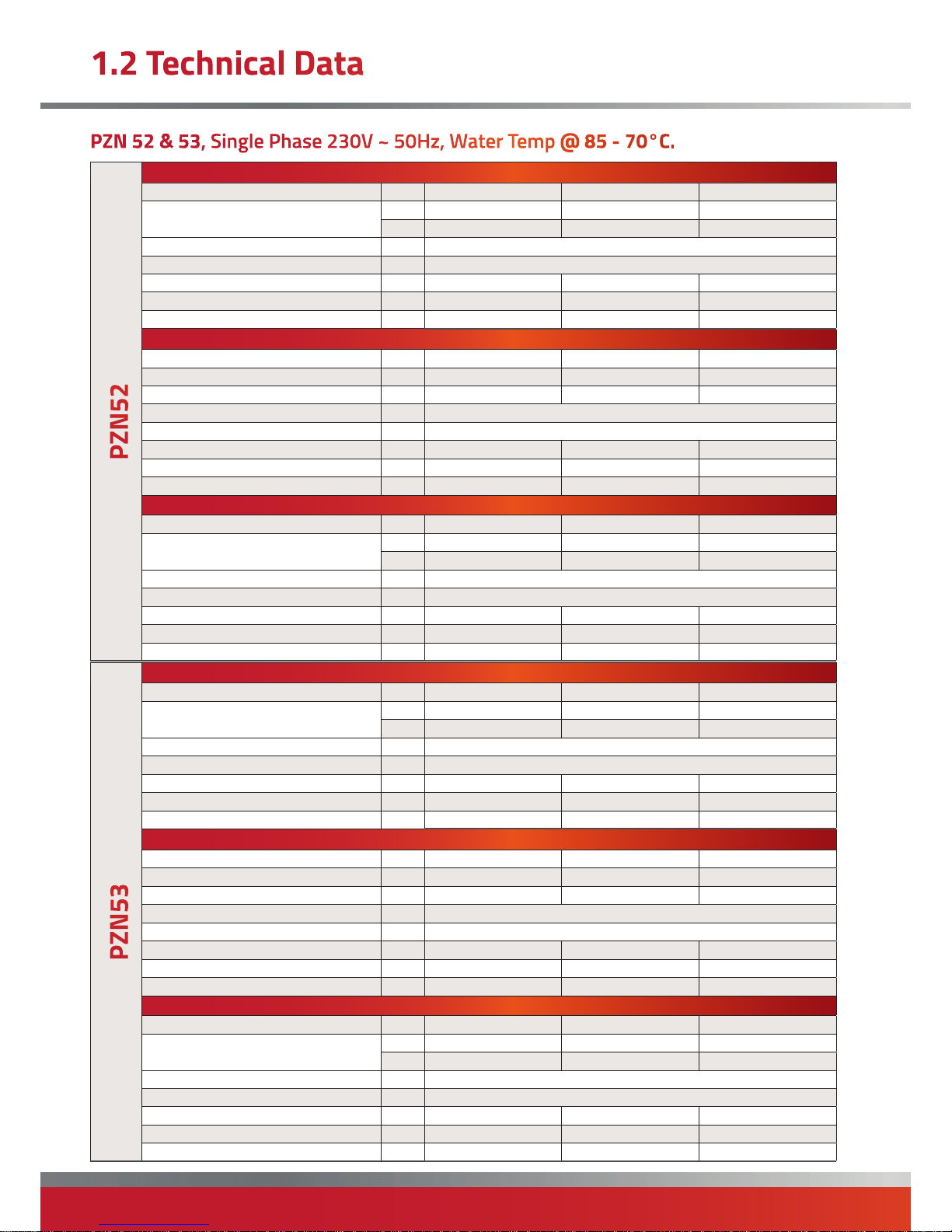
Fan heater at MAXIMUM fan speed.
Airflow Rate °C 15 20 25
Thermal Power
kW 31.9 29.1 26.3
Kcal/h 27400 25000 22650
Air Flow Rate m³/h 3950
Sound Pressure Level dB(A) 53
Air Outlet Temperature °C 39 42 45
Water Side Heat Loss kPa 20 17 14
Water Flow Rate l/h
1876 1712 1550
Fan heater at MEDIUM fan speed.
Airflow Rate °C 15 20 25
Thermal Power kW 27.7 25.3 22.9
Kcal/h 23850 21750 19700
Air Flow Rate m³/h 2800
Sound Pressure Level dB(A) 49
Air Outlet Temperature °C 44 47 50
Water Side Heat Loss kPa 15 13 11
Water Flow Rate l/h 1631 1489 1347
Fan heater at MINUMUM fan speed.
Airflow Rate °C 15 20 25
Thermal Power
kW 23.3 21.3 19.2
Kcal/h 20050 18300 16550
Air Flow Rate m³/h 1900
Sound Pressure Level dB(A) 43
Air Outlet Temperature °C 51 53 55
Water Side Heat Loss kPa 11 10 8
Water Flow Rate l/h 1371 1251 1132
Fan heater at MAXIMUM fan speed.
Airflow Rate °C 15 20 25
Thermal Power
kW 42.7 39.0 35.2
Kcal/h 36750 33500 30300
Air Flow Rate m³/h 3900
Sound Pressure Level dB(A) 43
Air Outlet Temperature °C 47 50 52
Water Side Heat Loss kPa 13 11 10
Water Flow Rate l/h
2514 2292 2073
Fan heater at MEDIUM fan speed.
Airflow Rate °C 15 20 25
Thermal Power kW 35.4 32.3 29.2
Kcal/h 30450 27750 25100
Air Flow Rate m³/h 2650
Sound Pressure Level dB(A) 49
Air Outlet Temperature °C 54 56 58
Water Side Heat Loss kPa 10 8 7
Water Flow Rate l/h 2084 1900 1718
Fan heater at MINUMUM fan speed.
Airflow Rate °C 15 20 25
Thermal Power
kW 29.2 26.6 24.1
Kcal/h 25100 22900 20700
Air Flow Rate m³/h 1850
Sound Pressure Level dB(A) 43
Air Outlet Temperature °C 61 62 64
Water Side Heat Loss kPa 7 6 5
Water Flow Rate l/h 1720 1567 1417
Page 13
page no. 13 of 28
PZN Aquamatic Water Heater Doc Ref M107 issue 1.3 Sep 2018.
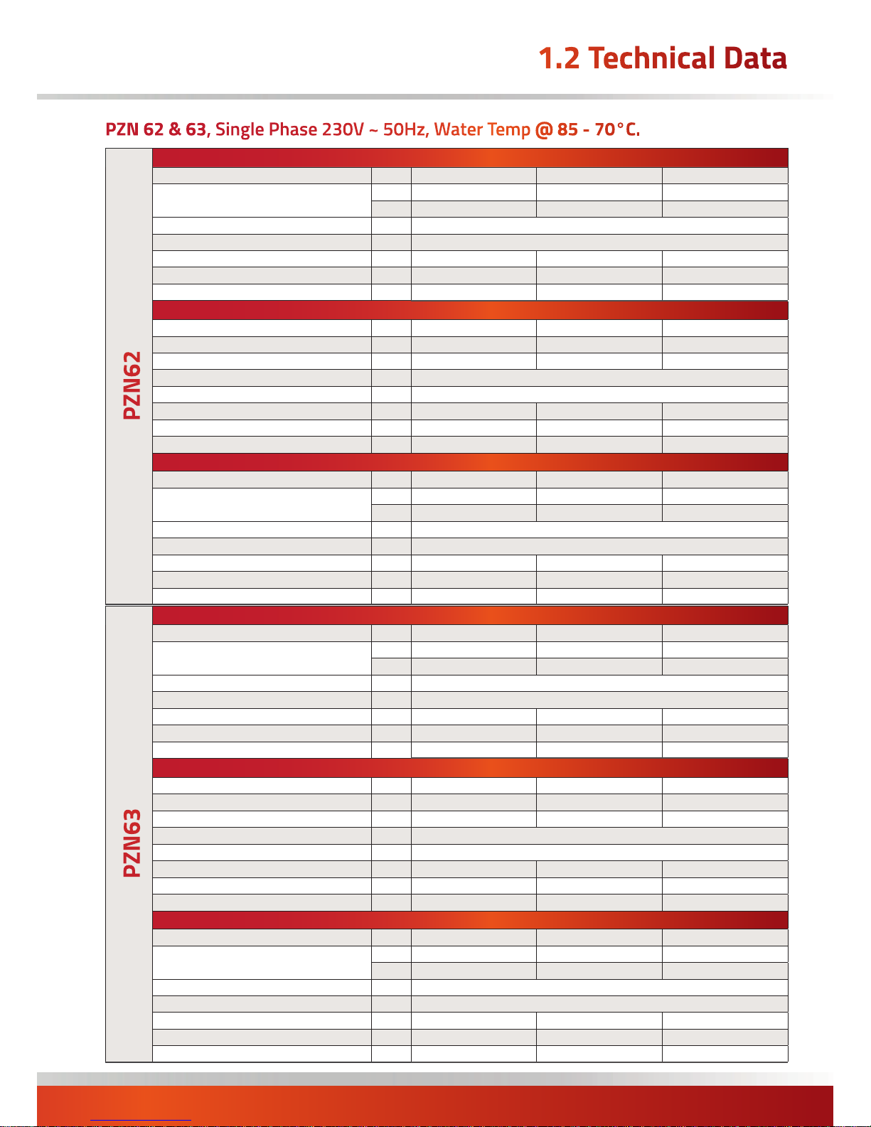
Fan heater at MAXIMUM fan speed.
Airflow Rate °C 15 20 25
Thermal Power
kW 39.1 25.6 32.2
Kcal/h 33600 30650 27700
Air Flow Rate m³/h 5200
Sound Pressure Level dB(A) 53
Air Outlet Temperature °C 37 40 44
Water Side Heat Loss kPa 13 11 9
Water Flow Rate l/h
2300 2098 1897
Fan heater at MEDIUM fan speed.
Airflow Rate °C 15 20 25
Thermal Power kW 32.9 29.8 26.9
Kcal/h 28050 25600 23150
Air Flow Rate m³/h 3300
Sound Pressure Level dB(A) 49
Air Outlet Temperature °C 44 47 50
Water Side Heat Loss kPa 9 8 7
Water Flow Rate l/h 1920 1751 1583
Fan heater at MINUMUM fan speed.
Airflow Rate °C 15 20 25
Thermal Power
kW 28.4 25.8 23.4
Kcal/h 14400 22200 20100
Air Flow Rate m³/h 2450
Sound Pressure Level dB(A) 47
Air Outlet Temperature °C 49 52 54
Water Side Heat Loss kPa 7 6 5
Water Flow Rate l/h 1668 1521 1375
Fan heater at MAXIMUM fan speed.
Airflow Rate °C 15 20 25
Thermal Power
kW 52.4 47.8 43.3
Kcal/h 45100 41150 37200
Air Flow Rate m³/h 4900
Sound Pressure Level dB(A) 53
Air Outlet Temperature °C 46 49 52
Water Side Heat Loss kPa 16 14 12
Water Flow Rate l/h
3086 2815 2547
Fan heater at MEDIUM fan speed.
Airflow Rate °C 15 20 25
Thermal Power kW 42.2 38.4 34.8
Kcal/h 36250 33050 29900
Air Flow Rate m³/h 3150
Sound Pressure Level dB(A) 49
Air Outlet Temperature °C 54 56 59
Water Side Heat Loss kPa 11 9 8
Water Flow Rate l/h 2481 2262 2046
Fan heater at MINUMUM fan speed.
Airflow Rate °C 15 20 25
Thermal Power
kW 34.8 31.6 28.6
Kcal/h 29900 27200 24600
Air Flow Rate m³/h 2200
Sound Pressure Level dB(A) 47
Air Outlet Temperature °C 61 63 64
Water Side Heat Loss kPa 8 7 6
Water Flow Rate l/h 2045 1863 1685
Page 14
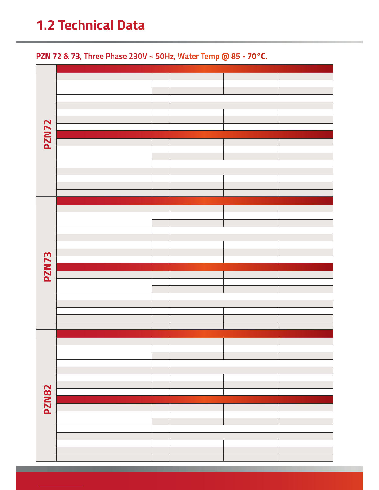
page no. 14 oF 28
PZN Aquamatic Water Heater Doc Ref M107 issue 1.3 Sep 2018.
Fan heater at MAXIMUM fan speed.
Airflow Rate °C 15 20 25
Thermal Power
kW 47.4 43.3 39.2
Kcal/h 40800 37250 33700
Air Flow Rate m³/h 6700
Sound Pressure Level dB(A) 52
Air Outlet Temperature °C 36 39 43
Water Side Heat Loss kPa 14 12 10
Water Flow Rate l/h 2793 2549 2305
Fan heater at MINUMUM fan speed.
Airflow Rate °C
15 20 25
Thermal Power
kW 41.0 37.4 33.8
Kcal/h 33250 32150 29100
Air Flow Rate m³/h 4550
Sound Pressure Level dB(A) 46
Air Outlet Temperature °C 41 44 47
Water Side Heat Loss kPa 11 9 8
Water Flow Rate l/h 2412 2200 1990
Fan heater at MAXIMUM fan speed.
Airflow Rate °C 15 20 25
Thermal Power
kW 63.0 57.4 51.9
Kcal/h 54150 49400 44650
Air Flow Rate m³/h 6200
Sound Pressure Level dB(A) 52
Air Outlet Temperature °C 45 48 50
Water Side Heat Loss kPa 12 10 8
Water Flow Rate l/h 3707 3380 3056
Fan heater at MINUMUM fan speed.
Airflow Rate °C
15 20 25
Thermal Power
kW 52.7 48.1 43.5
Kcal/h 45350 41350 37400
Air Flow Rate m³/h 4250
Sound Pressure Level dB(A) 46
Air Outlet Temperature °C 51 54 56
Water Side Heat Loss kPa 8 7 6
Water Flow Rate l/h 3105 2830 2559
Fan heater at MAXIMUM fan speed.
Airflow Rate °C 15 20 25
Thermal Power
kW 67.7 61.7 55.8
Kcal/h 58200 53100 48000
Air Flow Rate m³/h 8500
Sound Pressure Level dB(A) 54
Air Outlet Temperature °C 38 52 54
Water Side Heat Loss kPa 11 9 8
Water Flow Rate l/h 3985 3634 3286
Fan heater at MINUMUM fan speed.
Airflow Rate °C
15 20 25
Thermal Power
kW 61.0 55.6 50.3
Kcal/h 52500 47850 43300
Air Flow Rate m³/h 6550
Sound Pressure Level dB(A) 49
Air Outlet Temperature °C 42 45 48
Water Side Heat Loss kPa 9 8 6
Water Flow Rate l/h 3593 3276 2962
Page 15
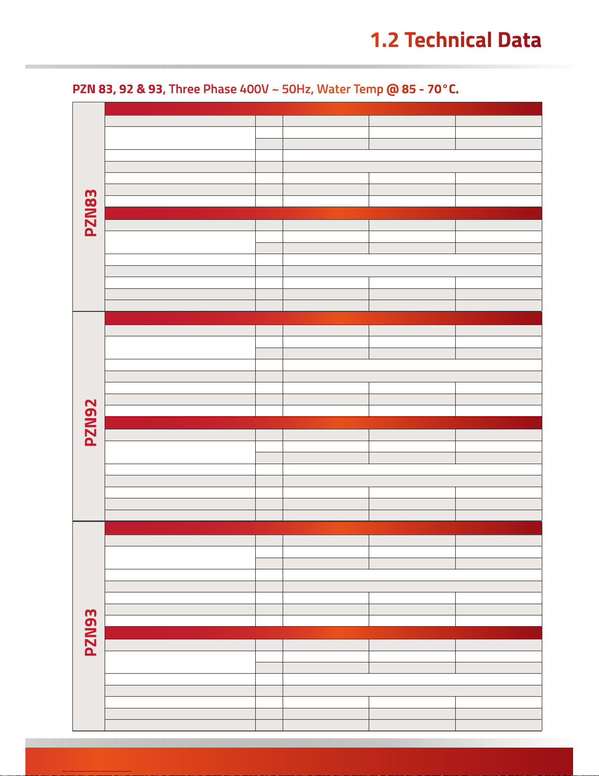
page no. 15 of 28
PZN Aquamatic Water Heater Doc Ref M107 issue 1.3 Sep 2018.
Fan heater at MAXIMUM fan speed.
Airflow Rate °C 15 20 25
Thermal Power
kW 87.8 80.1 72.4
Kcal/h 75550 68900 62250
Air Flow Rate m³/h 7700
Sound Pressure Level dB(A) 54
Air Outlet Temperature °C 48 51 53
Water Side Heat Loss kPa 9 8 6
Water Flow Rate l/h 5173 4715 4262
Fan heater at MINUMUM fan speed.
Airflow Rate °C
15 20 25
Thermal Power
kW 78.3 71.3 64.5
Kcal/h 67300 61350 55450
Air Flow Rate m³/h 6100
Sound Pressure Level dB(A) 49
Air Outlet Temperature °C 53 55 57
Water Side Heat Loss kPa 7 6 5
Water Flow Rate l/h 4607 4198 3794
Fan heater at MAXIMUM fan speed.
Airflow Rate °C 15 20 25
Thermal Power
kW 88.8 51.1 73.4
Kcal/h 66400 69750 63100
Air Flow Rate m³/h 12550
Sound Pressure Level dB(A) 53
Air Outlet Temperature °C 36 39 43
Water Side Heat Loss kPa 21 18 15
Water Flow Rate l/h 5229 4773 4321
Fan heater at MINUMUM fan speed.
Airflow Rate °C
15 20 25
Thermal Power
kW 78.0 71.2 64.4
Kcal/h 67050 61200 55400
Air Flow Rate m³/h 8950
Sound Pressure Level dB(A) 48
Air Outlet Temperature °C 41 44 47
Water Side Heat Loss kPa 17 14 12
Water Flow Rate l/h 4591 4190 3792
Fan heater at MAXIMUM fan speed.
Airflow Rate °C 15 20 25
Thermal Power
kW 114.9 104.8 94.9
Kcal/h 98800 90150 81600
Air Flow Rate m³/h 10900
Sound Pressure Level dB(A) 53
Air Outlet Temperature °C 46 49 51
Water Side Heat Loss kPa 17 15 12
Water Flow Rate l/h 6764 6171 5583
Fan heater at MINUMUM fan speed.
Airflow Rate °C
15 20 25
Thermal Power
kW 101.8 92.8 84.0
Kcal/h 87550 79850 72250
Air Flow Rate m³/h 8400
Sound Pressure Level dB(A) 48
Air Outlet Temperature °C 50 53 55
Water Side Heat Loss kPa 14 12 10
Water Flow Rate l/h 5994 5466 4945
Page 16
page no. 16 oF 28
PZN Aquamatic Water Heater Doc Ref M107 issue 1.3 Sep 2018.
All heaters must be fitted exclusively with original
accessories. The manufacturer shall not be held
responsible for any damage deriving from improper use
of the unit or from the use of non-original materials and
accessories.
All references to Law, standards, directives and technical
rules in this manual are to be considered as informative
only and valid at the date of printing of the Manual. The
entry into force of new provisions or amendments to
current laws does not represent an obligation of the
manufacturer towards third parties.
Repairs or maintenance must be performed by the
Technical Assistance Service or by qualified personnel in
accordance with this manual. Do not modify or tamper
with the appliance as dangerous situations can be created
and the manufacturer will not be liable for any damage
caused.
All connected systems (water supply, electrical
connections etc.) must be secured safely and must not
constitute obstacles or cause personnel to trip up.
PZN & PZN-X units comply with the following European
Directives:
Eletromagnetic Compatibility Directive: 2004/108/EC
Low Voltage Directive: 2006/95/EC
Machinery Directive: 2006/42/EC
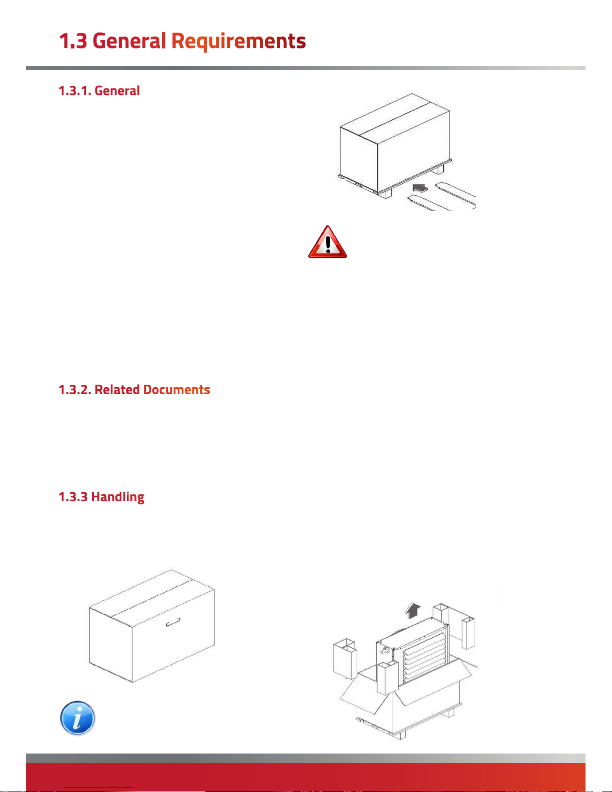
Handling must be done by properly equipped personnel.
All units are packaged in a cardboard box with handles for
handling.
Note: Units PZN 82 - 93 are packaged in a
cardboard box on a wooden base. Raise the
box with a fork-lift truck by inserting the forks
under the base.
Warnings:
• Do not move the heater by holding it by
the fins or by the fan motor.
• Shipping and handling must be carried out with
extreme care, so as to avoid damage to the unit and
danger to the people involved.
• During transportation and handling, it is forbidden to
stand near the unit.
• Use forklift forks with a minimum length equal to the
width of the machine.
• Should it be necessary
to place more than one unit on top of each other,
observe the index indicated on the packaging itself and
be very careful when aligning the packages so as not to
create unstable stacks.
• If the device needs to be moved by hand, make sure
that there is enough workforce available in proportion
with the weigh indicated in the section "DIMENSIONS
AND WEIGHT" and depending on the distance to cover.
• We suggest using protection gloves.
To remove the packaging proceed as follows:
• Cut the strap (PZN42 - 53 only);
• Open the upper part of the case;
• Remove the inner spacers;
• Pull the unit upwards out of the case.
Page 17
page no. 17 of 28
PZN Aquamatic Water Heater Doc Ref M107 issue 1.3 Sep 2018.
Note: Do not disperse the parts of the
packaging in the environment, or leave them
within the reach of children, as they are
potentially danger. For proper disposal contact
your local authorities.
The unit is sent in a single case and includes:
− UNIT HEATER
− PLASTIC BAG (A) containing:
• Instruction Manual;
• Warranty Certificate;
• Spare Parts catalogue;
• Label with barcode;
The booklet is an integral part of the unit and should be
read carefully and kept for future reference.
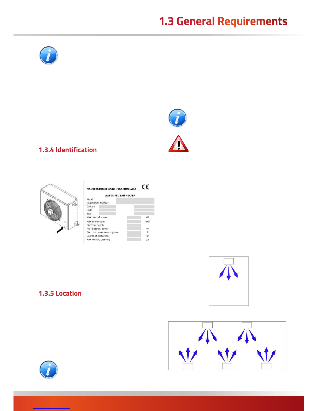
The unit can be identified by either
• the Technical Data plate (positioned on the rear of the
unit) which shows the main technical /performance data.
• the packaging label that shows the code, model and
serial number of the unit.
In case of damage or loss, request a duplicate from
Technical Assistance.
The location for the unit must be determined by the
system designer or a competent person and it must
take into account the technical requirements and the
standards and regulations in force; generally, special
permissions need to be obtained. (e.g.: regulations
concerning zoning, architecture, fires, environmental
pollution, noise emission, etc.). It is therefore advisable,
before installing the unit, to request and obtain the
necessary permissions.
Note: For proper installation always observe
the following minimum requisites:
• position the unit on a dry level surface capable of
sustaining its weight;
• respect the distances in order to allow for a correct flow
of air and normal cleaning and maintenance operations;
• position the unit in a place that makes water and
electrical connections convenient;
• be close to an electric socket;
Note: It is also necessary to make sure that:
The temperature range for use is between -15
and +40 °C
Warning: It is forbidden to install:
• in places where there are aggressive
atmospheres;
• in narrow places where the noise created by the
generator could be amplified by reverb or resonance;
• in corners where there is a deposit of dust, leaves and
anything that may reduce the efficiency of the unit by
blocking the air passage.
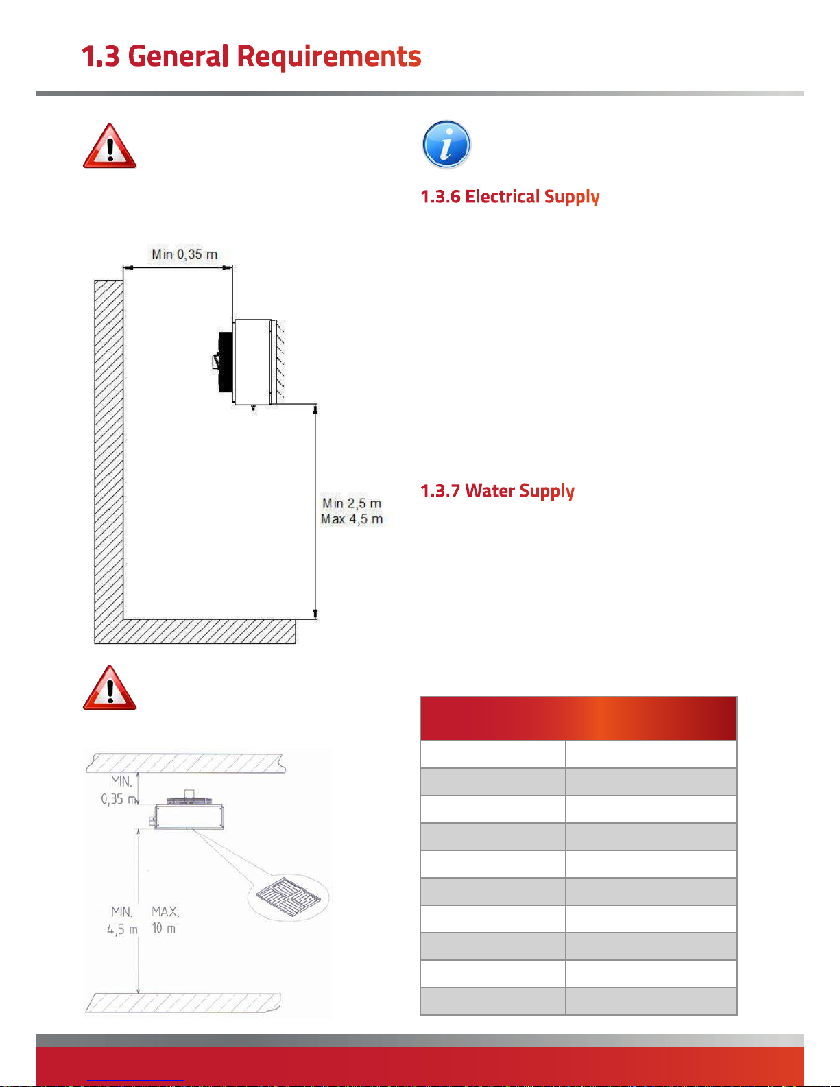
The unit is normally installed on a shelf in a higher
position as shown in the following figures. In this case
make sure that the shelves are attached to a suitable
structure by means of suitable fixing elements.
The unit features a helical fan and it is therefore suitable
to be connected to ducts with important load losses. For
special requirements, consult the Manufacturer.
Example of installation in a small room:
Example of installation in a large room/area:
Page 18
page no. 18 oF 28
PZN Aquamatic Water Heater Doc Ref M107 issue 1.3 Sep 2018.
Warning: Do not install outside and in places
with an aggressive environment.
Select the appropriate model on the basis of performance
data for average fan speed.
Example of vertical installation
Warning: To allow for proper air flow and
therefore the correct operation of the unit, it
is essential that there is no obstacle near the
outlet nozzle side panel.
Example of vertical installation
Note: When mounting the heater on the ceiling
it is recommended that you use the CEILING
INSTALLATION KIT.
Wiring external to the air heater must be installed in
accordance with the I.E.E. Regulations for Electrical
Installations and any local regulations which apply.
All standard heaters are supplied by 230V - 1ph, 50Hz.
The method of connection to the main electricity supply
must:-
- facilitate the complete electrical isolation of the unit(s)
via a suitable fused isolator (see section 2.4.5 for ratings)
- be in a readily accessible position adjacent to the unit(s)
- serve only the unit(s)
- have a contact separation of at least 3mm in all poles.
See the accompanying wiring diagram for the heater
electrical connections
The selection and installation of water system
components is the responsibility of the installer. The
installer must observe correct working practices and the
legislation in force at all times.
In systems filled with anti-freeze the use of water
disconnectors is compulsory.
Where the heater is supplied with special or recycled
water it must first be treated accordingly. Observe the
reference values in the table.
Reference Values
PH 6 – 8
Electrical conductivity less than 200mV/cm (25°C)
Chlorine ions less than 50 ppm
Sulphuric acid ions less than 50 ppm
Total iron less than 0.3 ppm
Alkalinity M less than 50 ppm
Total hardness less than 50 ppm
Sulphur ions none
Ammonia ions none
Silicon ions less than 30 ppm
Page 19
page no. 19 of 28
PZN Aquamatic Water Heater Doc Ref M107 issue 1.3 Sep 2018.
Before installation, check that the local distribution
conditions and adjustment of the appliance are
compatible.
The unit must be installed in accordance with the
rules in force and the relevant requirements of any
fire regulations or insurance company's requirements
appertaining to the area in which the heater is located,
If necessary consideration should be given to mounting
the heater on resilient pads, or equivalent, to minimise
transfer of noise and vibration to the structure of the
building.
Units mounted at high level must be supported on
a purpose designed platform or framework that is
suspended from vertical drop rods, chains or straps or
mounted on specifically designed cantilever brackets from
a non-combustible wall.
The method of installation support must be capable
of adequately supporting the weight of the unit (See
Technical Specification section) and any ancillary
equipment.
Before installing the heater the existing structure must be
inspected to ensure it is suitable.
All supports should be protected against the effects of
rust or corrosion.
If the method of mounting allows for any movement of
the heater it is essential that all gas, duct, and electrical
connections to the heater are made with flexible
connections to maintain continuity of connection.
The installation of the unit should be performed by a
qualified company that, at the end of the work, must give
the owner a declaration of conformity of the installation,
performed according to the book, that is in compliance
with the National and Local Standards in force and the
instructions provided in this instruction booklet.
The heaters have been manufactured for room heating
and they must be used for this purpose, compatibly with
their performance characteristics.
The manufacturer is exonerated from any contractual
or extra-contractual liability regarding damages caused
by incorrect installation, adjustment, maintenance or
improper use.
After unpacking the product, check its integrity and
wholeness. If not, contact the Agency that sold the unit.
In reference to standard CEI EN 60335-1, for electric
motors with rated current > 0.2 and ≤ 1.5, a deviation
equal to +20% is allowed. For this, the external electrical
protections (not supplied and to be provided by the
customer) located upstream of the device need to be
sized with an adequate margin that takes into account the
normal variables of the system.
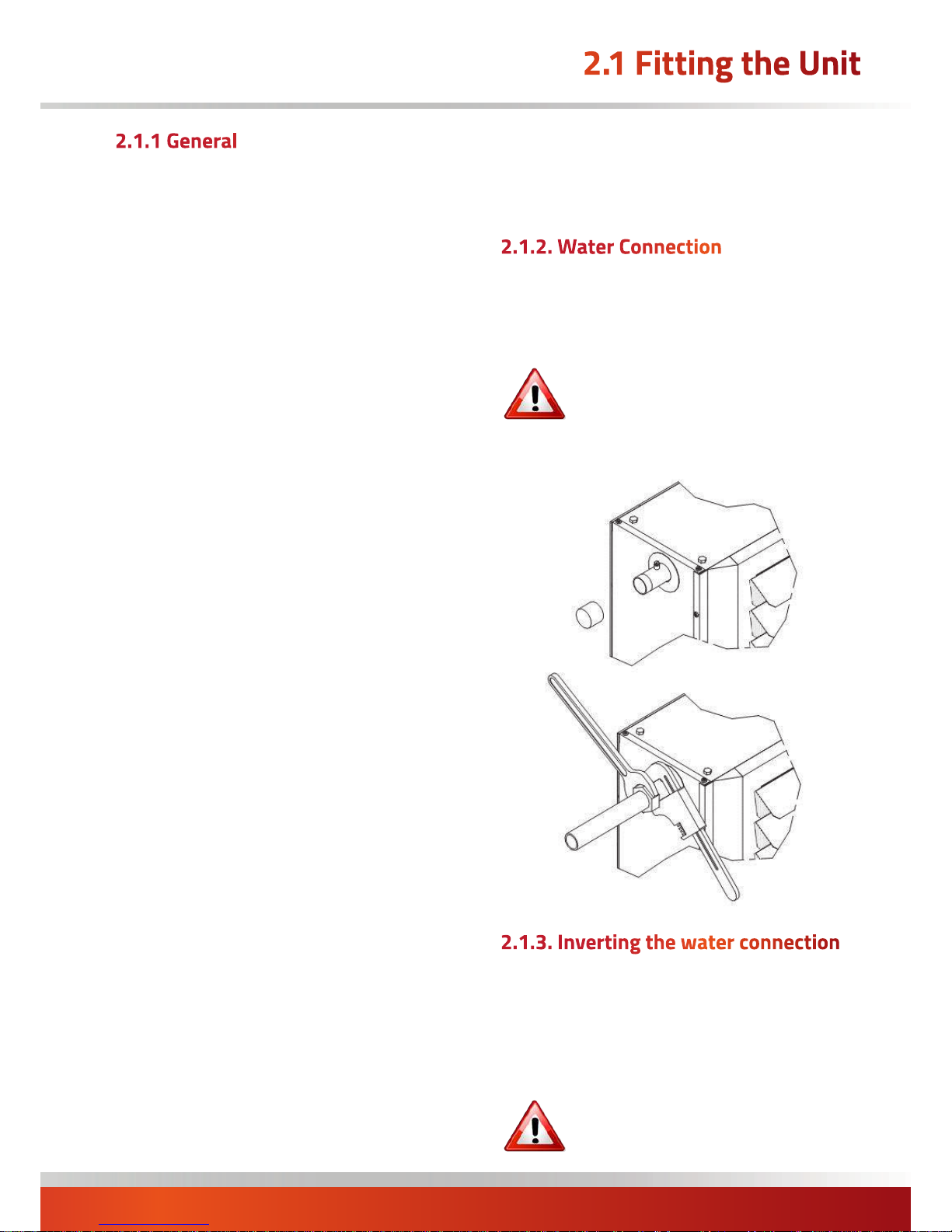
• Remove the plastic plugs from the water connection
fittings;
• Connect the system according to the hydraulic diagram
shown in the dedicated chapter.
WARNING: To prevent damage to the unit
secure the heater water fittings by using the
wrench – counterwrench method.
To seal the threads use hemp and green paste. Using
Teflon is inadvisable where anti-freeze is used.
WARNING!!!
have to leave the “red bridges into the electrical box of the fan.
To switch the water connections from one side to the
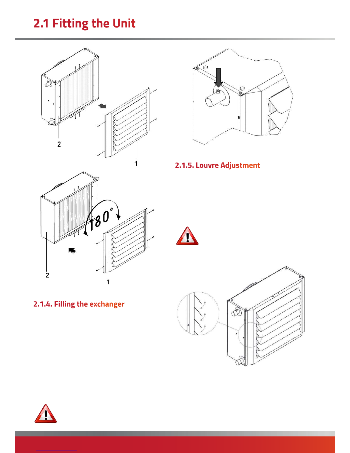
other proceed as follows:
• Disassemble the air outflow panel (1);
• Rotate the entire unit (2) 180°;
• Replace the air outflow panel (1).
WARNING: For optimum performance it is
essential that water inlet-outlet directions
always be observed as indicated by the
adhesive label.
Page 20
page no. 20 oF 28
PZN Aquamatic Water Heater Doc Ref M107 issue 1.3 Sep 2018.
• position the main switch to OFF.
• check that the water system drain valve is closed;
• open the upper manual bleed valve.
• start filling by slowly opening the water system filling
valve external to the heater unit;
• when water begins flowing out of the bleed valve
close the latter and continue filling until correct system
pressure is reached;
• repeat the procedure after the heater has been running
a few hours and periodically check pressure;
• check that there are no leaks.
WARNING: If there is a risk of sub-zero
temperatures mix some anti-freeze into the
water in manufacturer-recommended
quantities.
When the unit is delivered the directional louvres are
almost completely closed. The horizontal louvres must
be adjusted during installation so as to create an airflow
suitable for the room/area being heated. Such airflow
must not disturb the persons occupying such room/area.
The louvres can be individually adjusted manually.
Do not close the horizontal louvres
completely.
Adjust the flow directing fins by grabbing
them on the extremity.
Use suitable protective equipment.
Page 21
page no. 21 of 28
PZN Aquamatic Water Heater Doc Ref M107 issue 1.3 Sep 2018.
Warning: THIS APPLIANCE MUST BE
EARTHED.
Warning: Wiring external to the unit must be
carried out by an appropriately qualified
person to current IEE regulations for
Electrical Installations and any local regulations which
apply.
The local electrical supply must be run to a point adjacent
to the heater and be suitably terminated to provide an
isolation point that will prevent remote activation of
the unit during servicing. Wiring should be completed in
flexible conduit.
The local electrical supply conditions must be compatible
with the electrical data given on the appliance data plate.
Units for use with either 230V, 1N, 50Hz or 400V, 3N,
50Hz supplies. (see section 1.2 for details)
The method of connection to the main electricity supply
must:-
- facilitate the complete electrical isolation of the unit(s)
via a suitable fused isolator that will prevent remote
activation of the unit during servicing (see section 1.2 for
ratings).
- be in a readily accessible position adjacent to the
heater(s).
- serve only the units(s).
- have a contact separation of at least 3mm in all poles.
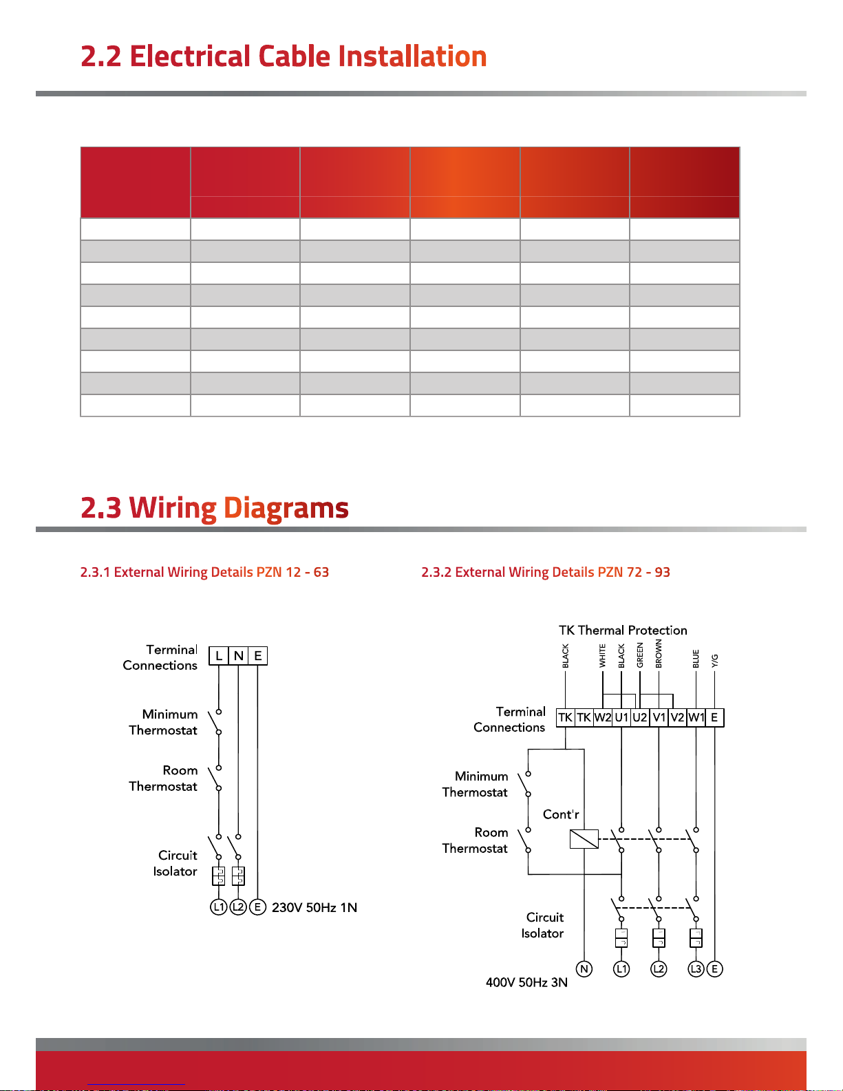
See section 2.5 or the accompanying wiring diagram for
the heater electrical connections.
Reference must be made to Section 1.2 to ascertain the
electrical loading of the unit(s) being installed so that
cables of adequate cross-sectional area are used for
the electrical installation. The length of the conductors
between the cord anchorage and the terminals must be
such that the current carrying conductors become taut
before the earth conductor if the cable or cord slips out
of the cord anchorage. All external controls must be of an
approved type.
All units are fully pre-wired and only require final
connections for the incoming mains supply and any
controlling circuits such as on-off switches, room
thermostats, three position speed controls etc.
Notes:
• Install upstream of the unit a differential magneto
thermal circuit breaker suitably sized according to the
regulations in force.
• Always connect the earthing system, taking care to
leave the earth wire slightly longer that the other wires,
so that, in case of accidental pulling, the latter is the last
one to be removed.
• Get qualified personnel to check that the section of
the cables and the electrical system are suitable for the
maximum power absorbed by the unit indicated on the
information plate.
• Respect polarity in the connection of the power supply
(phase - neutral).
• The unit must be connected to an efficient earthing
system. The manufacturer shall not be held responsible
for any damage caused by failure to earth the appliance.
• The electrical cables must be positioned so as not to
come into contact with hot and/or cold surfaces, or with
sharp edges.
• In accordance with the Standards regarding the
installation of electrical components, a device that
ensures disconnection from the mains with an opening
distance between contacts that guarantees complete
disconnection in overvoltage conditions III (Standard EN
60335-1) must be included.
• Water or gas pipes should not be used as earth
connection of the machine.
• It is compulsory to use systems that, in the event of a
fan heater breakdown, isolate the faulty unit only without
compromising the routine operation of any other units
making up the overall system.
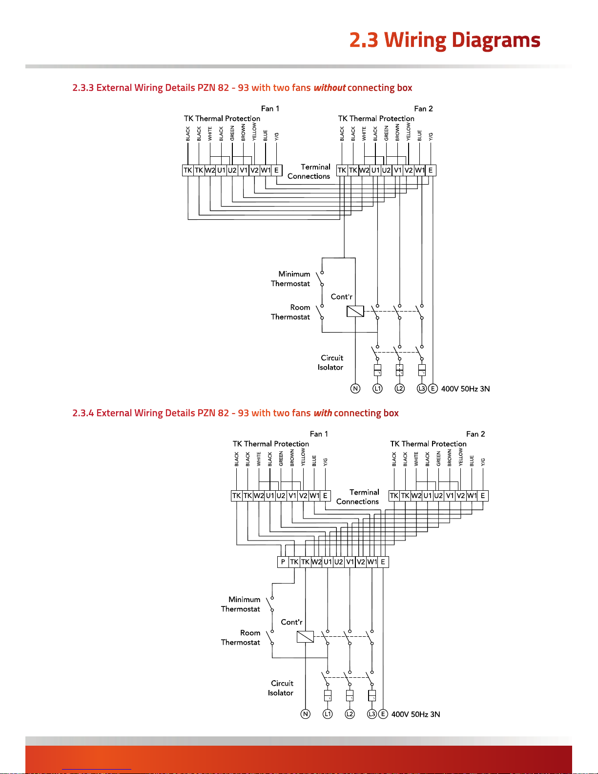
• In the types with two electric fans (PZN 82 - 93)
to activate it is possible to feed the two assemblies
separately
Page 22
page no. 22 oF 28
PZN Aquamatic Water Heater Doc Ref M107 issue 1.3 Sep 2018.
Size
Voltage Power
Supply
Max Power
Absorbed
Max Current
Absorbed
Line Fuse ¹ Cable Size ²
(V ph Hz) (W) (A) (A) (mm²)
12/13 230V ~ 50Hz 74 0.34 1 1.5
22/23 230V ~ 50Hz 86 0.38 1 1.5
32/33 230V ~ 50Hz 120 0.55 1 1.5
42/43 230V ~ 50Hz 130 0.60 1 1.5
52/53 230V ~ 50Hz 200 0.90 2 1.5
62/63 230V ~ 50Hz 220 0.95 2 1.5
72/73 400V 3N ~ 50Hz 305 0.70 2 1.5
82/83 400V 3N ~ 50Hz 240 0.56 2 1.5
92/93 400V 3N ~ 50Hz 610 1.40 2 1.5
¹ Not suppled
² Wire cross-section ensures a voltage drop of less than 5% for a length of 30 m
Wire sizing table:
Page 23
page no. 23 of 28
PZN Aquamatic Water Heater Doc Ref M107 issue 1.3 Sep 2018.
Page 24
page no. 24 oF 28
PZN Aquamatic Water Heater Doc Ref M107 issue 1.3 Sep 2018.
Checks to ensure electrical safety must be carried out by
a qualified person.
Activating the heating function
• Switch on the electrical supply at the isolator.
• Position the main switch to ON.
• Set fan speed as desired (where speed selector
switch is installed).
• Set room thermostat to desired temperature (higher
than current room temperature).
• At this point both the water circulator and the
heater fan start simultaneously. To prevent an initial
outflow of unpleasant cold air it is possible to delay
fan start-up with the aid of a minimum thermostat
(not supplied as accessory). This thermostat also
delays fan shutdown so as to disperse all the heat
accumulated in the exchanger into the room/area to
be heated.
• Once the temperature set on the room thermostat
has been reached the heater will shut down. When
the temperature drops back down below this setting
the fan heater restarts automatically.
Deactivating the heating function
• Deactivate the fan heater by acting on the room
thermostat;
• Turn the main switch to OFF.
• Close the water check valves.
WARNING: If there is a risk of sub-zero
temperatures and the system water does not
contain an anti-freeze liquid you must drain
the system.
Once the fan heater has been started check that it shuts
down on reaching the required temperature and then
restarts again when the room cools down (adjust the
room thermostat settings if necessary).
With the fan heater running:
• Check that the fan(s) rotates the right way.
• Check that fan(s) operates at the various speeds
(where fan speed control switch is installed).
• Check that electrical absorption is less than indicated
in the Technical Specification section.
• Check that there are no water leaks.
• Check that the fins are not too close together and
that there is no obstruction to airflow.
• If the fan heater passes all these checks it may be
restarted.
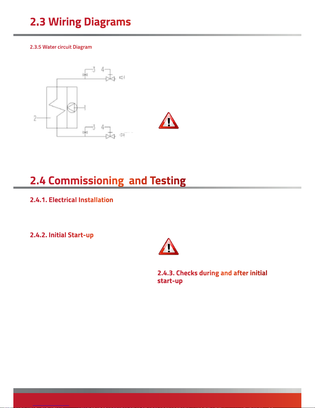
OUTPUT
INPUT
1. Helical fan(s)
2. Water-air exchanger
3. Manual air bleed
4. Spherical check valve (not supplied)
WARNING: Install a drain valve at the lowest
point in the water circuit to empty the system
when necessary.
Page 25
page no. 25 of 28
PZN Aquamatic Water Heater Doc Ref M107 issue 1.3 Sep 2018.
• Checking the pressure of the system
Regularly check the pressure of the system, so as to
allow the unit to operate in optimal conditions.
Do not exceed the maximum working
pressure limit indicated in chapter TECHNICAL
DATA.
• Clean external panels
This cleaning should only be carried out with damp cloths
with soap and water. For stubborn stains, moisten the
cloth with a mixture of 50% water and 50% denaturated
alcohol or specific products. After cleaning, dry the
surfaces carefully.
Do not use sponges soaked in abrasive
products or powder detergents.
• Clean fan
Remove any dust and/or foreign objects that may have
deposited on the fan and/or grating with compressed air.
• Clean heat exchanger
Remove the air outflow grating. Then clean off any dust
that may have deposited on the exchanger fins with the
aid of compressed air.
WARNING: For heavily used installations,
maintenances should be carried out every 6
months.
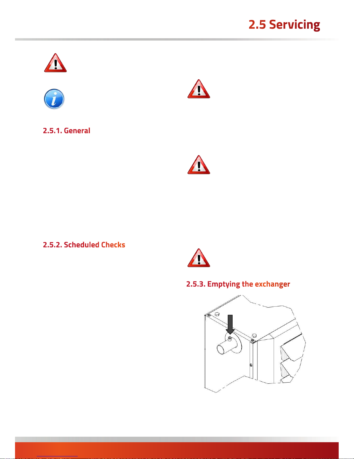
• position the main switch to OFF.
• check that the water system drain valve is closed;
• open the manual bleed valves (shown)
• open the system drain valve and drain all the water;
WARNING: Always switch off and disconnect
electricity supply and close the water check
valve before carrying out any servicing work
or replacement of failed components.
NOTE: If a suspended unit is to be serviced do
not lean ladders against the heater.
Ensure that an access tower or equivalent is
used.
Full maintenance should be undertaken not less than once
per year by a qualified person.
No 'specialised 'tools will be required to carry out this
service.
A fault finding guide is given in section 3.1 to aid servicing.
After any servicing work has been complete, or any
component replaced, the air heater(s) must be fully
commissioned and tested for soundness as described in
Section 2.6.
The following checks should be carried out during an
annual maintenance:
• Check for air in circuit
Loosen the manual bleed valves and check that there is
no air.
• Check voltage
Using a voltmeter check that the power supply is as
indicated on the technical data plaque (tolerance ± 10%).
• Check absorption
Using an ammeter check that the electrical current of
each phase is less than that indicated on the technical
data plaque.
• Check electrical connections
Disassemble the electrical connections box and check that
all the terminal grips are tightened properly.
• Check water couplings
Check for leaks along the entire circuit.
Page 26
page no. 26 oF 28
PZN Aquamatic Water Heater Doc Ref M107 issue 1.3 Sep 2018.
• close the manual bleed valves and remove any trace of
water from the system with the aid of compressed air.
WARNING: If the system contains anti-freeze
the water must be collected and, where
possible, re-used. Do not dump as with
normal water, because the anti-freeze is a
pollutant.
• position the main switch to OFF.
• check that the water system drain valve is closed;
• open the upper manual bleed valve.
• start filling by slowly opening the water system filling
valve external to the heater unit;
• when water begins flowing out of the bleed valve
close the latter and continue filling until correct system
pressure is reached;
• repeat the procedure after the heater has been running
a few hours and periodically check pressure;
• check that there are no leaks.
WARNING: If there is a risk of sub-zero
temperatures mix some anti-freeze into the
water in manufacturer-recommended
quantities.
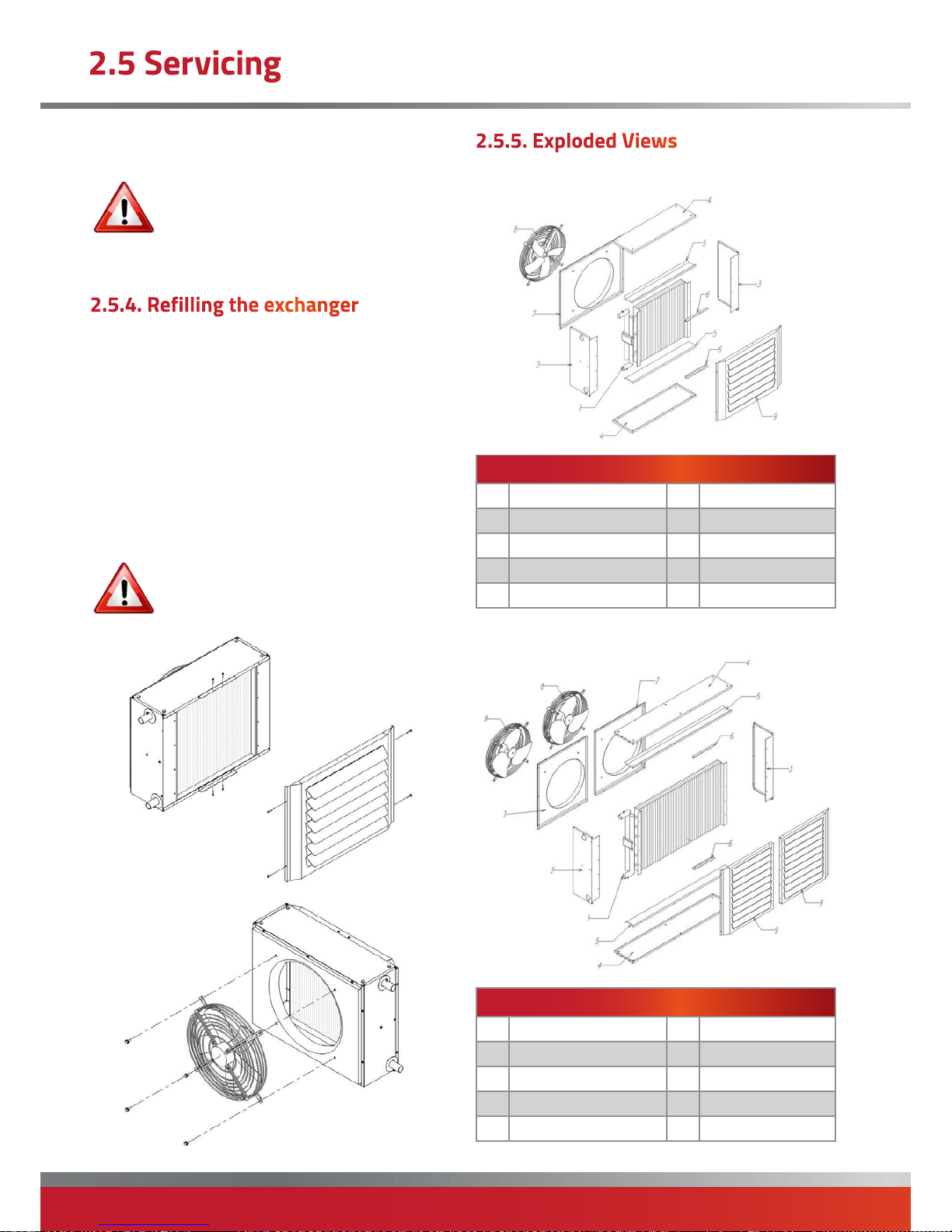
2.5.5.1 PZN 12 - 73
STRUCTURE
Item
1 Heat Exchanger 6 Fixing brackets
2 LHS panel 7 Rear panel
3 RHS panel 8 Fan
4 Top/Bottom panel 9 Outlet Louvre
5 Strengthening brackets
2.5.5.2 PZN 82 - 93
STRUCTURE
6 Fixing part
7 Fixing part
8 Fan(s)
9 Outflow grating
18
Item
1 Heat Exchanger 6 Fixing brackets
2 LHS panel 7 Rear panels
3 RHS panel 8 Fans
4 Top/Bottom panel 9 Outlet Louvres
5 Strengthening brackets
Page 27
page no. 27 of 28
PZN Aquamatic Water Heater Doc Ref M107 issue 1.3 Sep 2018.
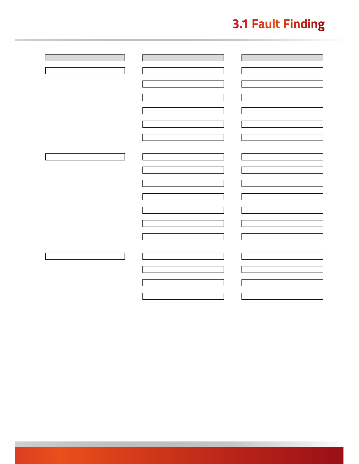
38.0 TROUBLESHOOTING
PROBLEM
CAUSE
SOLUTION
THE FAN DOES NOT START
No power
Check unit is powered
Main switch turned to OFF
Turn to ON
Room thermostat faulty
Check room thermostat
Fan faulty
Check fan motor
Condenser faulty
Check condenser
Overload cut-out tripped
Check absorption
POOR HEATING EFFICIENCY
Heat exchanger dirty
Clean exchanger
Airflow obstructed
Remove obstruction
Improper room temp. setting
Check regulation
Wrong water temperature
Check water temperature
Air in water circuit
Bleed air from system
Fan faulty
Check fan motor
Fan rotation inverted
Check direction of fan rotation
NOISE OR VIBRATION
Contact between metal parts
Inspect for contact
Screws loose
Tighten
Fan improperly balanced
Replace
Fan dirty
Clean
Page 28
page no. 28 oF 28
PZN Aquamatic Water Heater Doc Ref M107 issue 1.3 Sep 2018.
Stamm International Corporation
PO Box 1929
Fort Lee, NJ 07024
Tel: 201-947-1700
Fax: 201-947-9662
E-mail: stamminc@pobox.com
Stamm International HQ
www.powrmatic.co.uk
Powrmatic Limited
Hort Bridge, Ilminster
Somerset
TA19 9PS
tel: +44 (0) 1460 53535
fax: +44 (0) 1460 52341
e-mail: [email protected]
web: www.powrmatic.co.uk
Powrmatic Ireland
45 Broomhill Close
Tallaght
Dublin 24
tel: +353 (0) 1452 1533
fax: +353 (0) 1452 1764
e-mail: [email protected]
web: www.powrmatic.ie
Getting In Touch
Powrmatic pursues a policy of continues improvement in both design and performance of its products and therefore reserves the right to change, amend or
vary specifications without notice. Whilst the details contained herein are believed to be correct they do not form the basis of any contract and interested
parties should contact the Company to confirm whether any material alterations have been made since publication of this brochure.
EURO-AIR
QUALITY
ICOM
Energy Association
More information is available from our website by scanning the following QR code.
 Loading...