

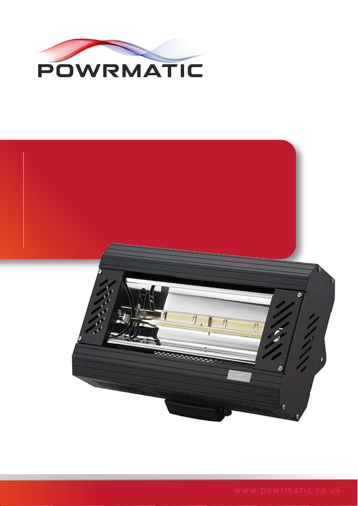
Powrmatic PQ-A1A010, PQ-A1C030, PQ-A1B030, PQ-A1B040, PQ-A1C045 User, Installation & Servicing Manual
...Page 1
www.powrmatic.co.uk
PQ-A
Doc Ref: M308 Issue 1.1 May 2019
®
User, Installation & Servicing Manual
Issue 1.1 May 2019
Page 2

Certificate Of Guarantee
®
Certificate of Guarantee
This is to certify that this heater is guaranteed for two years parts and one year labour from the date
of original commissioning. The heater must be commissioned within 4 weeks of installation.
To make a claim
In the first instance you must contact your appliance supplier, or installer and provide:-
1. The appliance type and serial number.
2. The original commissioning documentation. As much detail as possible on the fault.
3. Your supplier, or installer, will then contact Powrmatic to make a guarantee claim on your behalf.
Conditions of Guarantee
1. The heater must have been installed by a competent qualified installer, and in
accordance with the manufacturer’s instructions, building regulations and local regulations.
2. The heater has been professionally commissioned, within 4 weeks of installation, and a copy of
the commissioning sheet returned to Powrmatic.
3. The heater has been maintained on a yearly basis by a competent and qualified servicing
company.
4. The heater has been used in accordance with the manufacturer’s instructions.
5. The correct specification fuel has been used.
6. No unauthorised repairs of modifications have been made. Powrmatic ‘General Conditions of
Sales’ have been observed.
7. Except for the obligation of Powrmatic Ltd to perform warranty repairs during the guarantee
period, Powrmatic will not be liable in respect of any claim for direct or indirect consequential
losses, including loss of profits or increased cost arising from loss of use of the heater, or any
event arising there from.
Exclusions
Consumables such as fusible links, control batteries are all excluded from guarantee.
----------------------------------------------------
Powrmatic Ltd, Hort Bridge, Ilminster, Somerset, TA19 9PS
Tel: 01460 53535 Fax: 01460 52341
Web: www.powrmatic.co.uk e-mail: [email protected]
Important: This certificate
must be kept with the appliance
Failure to provide a copy of the commissioning sheet invalidates the heater warranty
page no. 2 of 16
PQ-A Range Users, Installation & Servicing Instructions Doc Ref M308 issue 1.1 May 2019.
Page 3
Contents
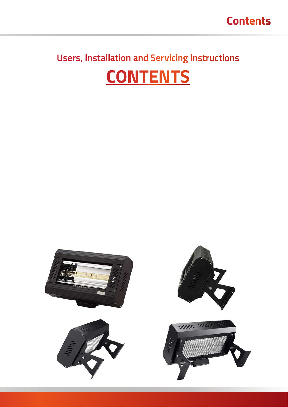
Users, Installation and Servicing Instructions
CONTENTS
Title Section Contents Page
User Instructions 4
Pre Installation
1.1 Introduction 4
Dimensions 6
1.2 Technical data 9
Installation
2.1 Installation 10
2.2 Maintenance 12
PQ-A Range Users, Installation & Servicing Instructions Doc Ref M308 issue 1.1 May 2019.
page no. 3 of 16
Page 4
User Instructions
If the heater has not been left operational
proceed as follows.
A) Checks before operating the Air
Heater
The following preliminary checks should be made before
lighting the heater(s)
a) Ensure that the ELECTRICAL supply to the controller/
external switch/heater is switched ON.
b) Ensure there is no foreign objects inside the grille or
covering the body of the heater.
B) Operating the Air Heater
Switch ON via the external switch/push button timer/
1.1 Introduction
external controller. To deactivate, switch OFF via the
external switch/push button timer/external controller.
C) IMPORTANT
To maintain correct, efficient, reliable and safe operation
of the heater it must serviced by a qualified person.
Free access must be maintained to and around the heater
for servicing purposes and the air supply to the heater
must not be restricted in any way. Combustible materials
must not be stored adjacent to the heater.
All Powrmatic heaters use electricity to power them.
It would be hazardous to tamper with or attempt to
service unless you are a competent person in the field of
Electrical work.
If you have any safety questions reference the servicing
and installation of any of our heaters please do not
hesitate to contact our head office for expert advice. Your
safety is paramount to us.
The Powrmatic A-Range of high powered heaters have
been designed and manufactured at the highest standard
to provide radiant heat to commercial and industrial
environments at high level and are available in heat
outputs of 1kW to 18kW.
The A-Range boasts all of the performance benefits
associated with full quartz shortwave technology
while providing an economic solution for industrial
and commercial heating requirements. It offers all the
convenience of electricity together with very low running
costs when compared to other forms of heating.
The range of quartz infrared heaters to suit any
application requiring a reliable heating solution including
commercial, domestic, outdoor and industrial heating
with reliability, durability and virtually maintenance free
benefits.
Profile Design
Use of dedicated extruded aluminium profile. This helps
the powerful heaters stay cool during running time. The
aluminium profile is lightweight and eliminates rusting
and discoloration.
Unique designed integral aluminium heat sinks
additionally help keep the heater cool and improve
reliability compared with inferior alternatives on the
market.
Shortwave Technology
full shortwave technology is noiseless and contributes
to no atmospheric pollution and no movement of dust
or other particles, which can be important in many
environments.
Parabolic Reflectors
The unique deep, smooth parabolic reflectors produced
using high grade anodised aluminium provides superior
consistent reflectivity through 100% of the reflector. This
provides intense uniformed heat coverage across a larger
area. The 0.8mm thick reflector effortlessly projects
heat forwards and in turn provides unbeatable heat
performance.
Durability
hard wearing / durable, reliable and designed to stand
hours of consistent commercial / industrial use.
It has been engineered to dissipate heat in order to keep
the body running cool which in turn increases life of the
product and its components.
Installation Flexibility
dedicated bracketry provide flexibility when installing on
side walls or overhead. also the swivel bracket (selected
models) offer directional heat where required which
makes the Apollo an easy to install flexible heating
solution.
Energy Saving Controls
compatible with energy saving controllers which
provides both controllability of heat output and energy
saving benefits to all models including the three phase
configuration which can be variably controlled.
IMPORTANT
Service and Maintenance Engineers shall
ensure that replacement items are fitted,
adjusted and set in accordance with the
data and detail set out in these instructions. If in doubt
consult Powrmatic Technical Department.
page no. 4 of 16
PQ-A Range Users, Installation & Servicing Instructions Doc Ref M308 issue 1.1 May 2019.
Page 5
User Instructions
CAUTION:
When using electrical heaters, basic
precautions should always be followed to
reduce the risk of fire, electric shock, and injury
to persons, including the following:
Read all instructions before using this heater.
• Before using this appliance:
- Check that the voltage indicated on the type plate
corresponds to the mains supply voltage.
- Ensure that the heater has been securely fastened in its
final mounting position.
• Do not locate the heater immediately below a socket
outlet.
• This appliance can be used by children aged from 8
years and above and persons with reduced physical,
sensory or mental capabilities or lack of experience
and knowledge if they have been given supervision or
instruction concerning use of the appliance in a safe way
and understand the hazards involved. Children shall not
play with the appliance. Cleaning and user maintenance
shall not be made by children without supervision.
• Children of less than 3 years should be kept away unless
continually supervised.
• Children aged from 3 years and less than 8 years shall
only switch on/ off the appliance provided that it has
been placed or installed in its intended normal operating
position and they have been given supervision or
instruction concerning use of the appliance in a safe way
and understand the hazards involved. Children aged from
3 years and less than 8 years shall not plug in, regulate
and clean the appliance or perform user maintenance.
• Arrange the mains supply cord so it cannot be tripped
over or damaged.
• Do not cover or obstruct the heater while it is in use.
• Do not should any item be place any item on or above
any part of the heater, whether the heater is being used
or not.
• Do not insert any object through any slot or opening in
the heater.
• Do not use if a guard is not present.
• Do not install less than the minimum mounting distance
from the floor.
Warning: This heater is not equipped with a
device to control the room temperature. Do
not use this heater in small rooms when they
are occupied by persons not capable of leaving
the room on their own, unless constant supervision is
provided.
• This heater is for indoor use only - do not install
outdoors or use the heater in a damp area, for example a
bathroom, laundry areas and similar locations or near to a
swimming pool. Never locate the heater where it may fall
into a bathtub or other water container.
• Do not expose to rain, snow, etc.
• A heater has hot parts inside. Do not use it in areas
where petrol, paint, or flammable liquids are used or
stored.
Warning: This appliance must be connected to
a supply that is earthed!
CAUTION: - Some parts of the product can
become very hot and cause burns. Particular
attention has been given where children and
vulnerable people are present.
Warning: UNDER NO CIRCUMSTANCES should
any person attempt to touch any of the lamps
whilst the unit is switched on or when it has
been recently used.
• Remove the plug from the mains socket (or disconnect
pole switch) during installation, cleaning and/or replacing
the element and always ensure that the element is cool.
• Do not handle the halogen lamp with bare hands. If it is
inadvertently touched, remove finger marks with a soft
cloth and methylated spirit or rubbing alcohol, otherwise
the marks will burn into the quartz glass, causing
premature heater failure.
• Do not use an extension cord with this product because
the extension cord may overheat and cause a risk of fire.
• Keep the mains supply cord away from the body of the
heater which will get hot during use.
Warning: - RISK OF FIRE
Keep combustible material such as furniture,
papers, clothes and curtains the safe distance
as marked on the heater from the front of the
heater and away from the sides and rear.
See on heater label
IMPORTANT - SAVE THESE INSTRUCTIONS FOR FUTURE
REFERENCE.
PQ-A Range Users, Installation & Servicing Instructions Doc Ref M308 issue 1.1 May 2019.
page no. 5 of 16
Page 6
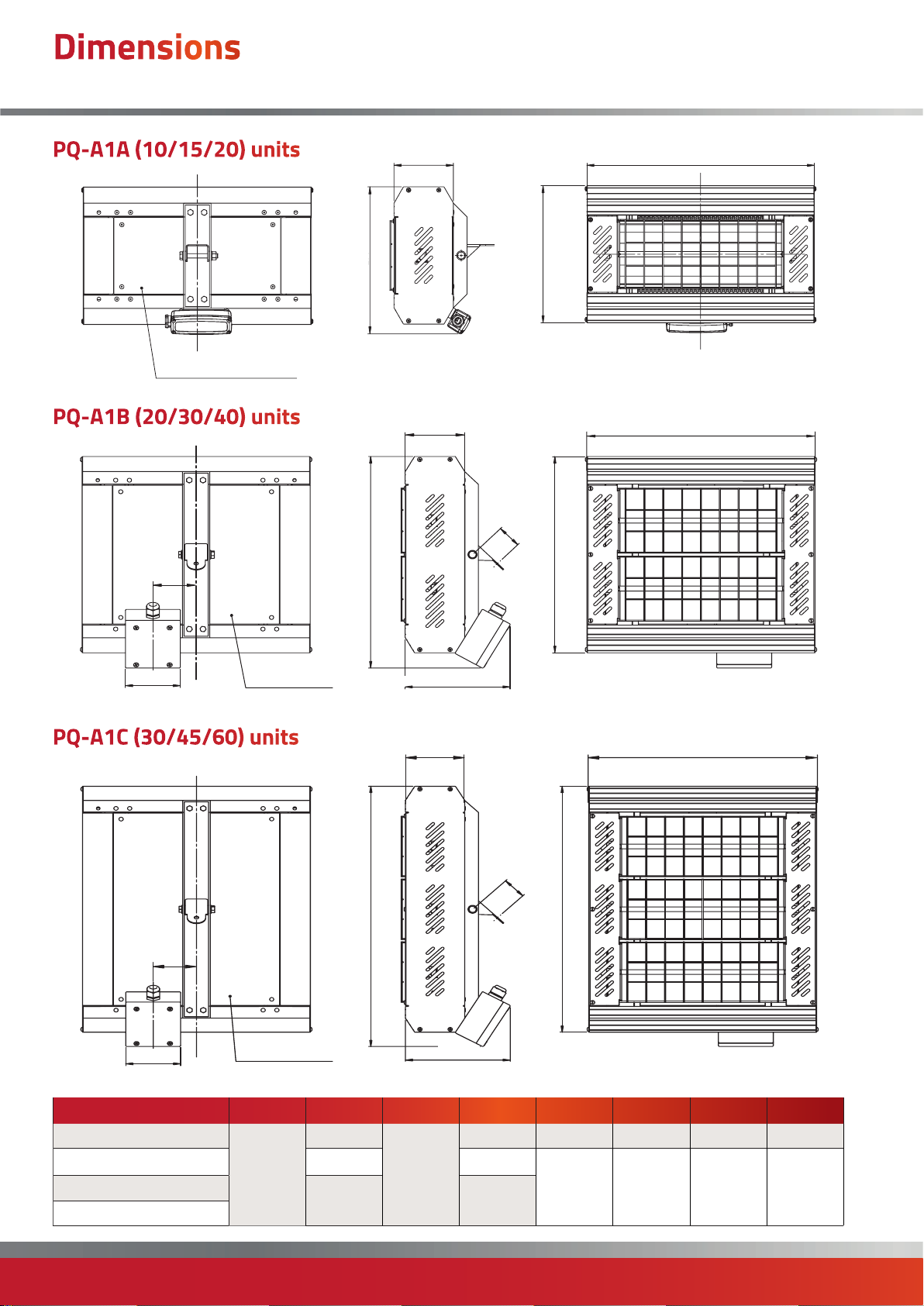
Dimensions
PQ-A
PQ-A1A (10/15/20) units
BACK
MESH - PATTERN NOT SHOWN
PQ-A1B (20/30/40) units
F
AC
D
SIDE
B
FRONT
AC
H
D
B
E
MESH - PATTERN NOT SHOWN
SIDE
PQ-A1C (30/45/60) units
D
F
E
PQ- A1A010/015/020
PQ- A1B020/030/040 390 420
PQ- A1C030/045/060
PQ- A3C030/045/060
MESH - PATTERN NOT SHOWN
SIDE
A B C D E F G H
255
422
525 555
110
G
FRONTBACK
AC
H
B
G
273 n/a n/a n/a n/a
FRONTBACK
102 80 194 45
page no. 6 of 16
PQ-A Range Users, Installation & Servicing Instructions Doc Ref M308 issue 1.1 May 2019.
Page 7
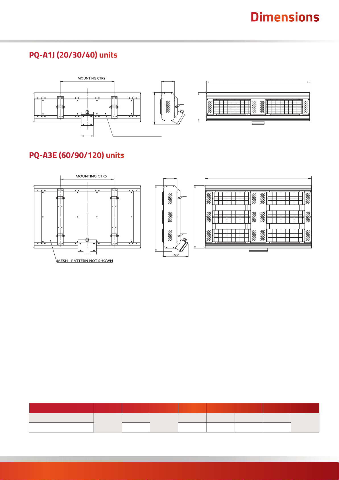
PQ-A1J (20/30/40) units
Dimensions
PQ-A
BACK
J
MESH - PATTERN NOT SHOWN
E
PQ-A3E (60/90/120) units
BACK
J
SIDE
FRONT
AC
D
B
FRONT
AC
D
B
MESH - PATTERN NOT SHOWN
PQ- A1J020/030/040
PQ- A3E060/090/120 630 663 102 n/a 199
E
A B C D E F G J
255
857
G
285 102 n/a n/a
110
435
PQ-A Range Users, Installation & Servicing Instructions Doc Ref M308 issue 1.1 May 2019.
page no. 7 of 16
Page 8
Dimensions
PQ-A
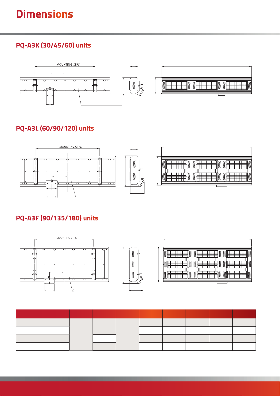
PQ-A3K (30/45/60) units
BACK
H
F
E
MESH - PATTERN NOT SHOWN
PQ-A3L (60/90/120) units
BACK
J
F
E
MESH - PATTERN NOT SHOWN
SIDE
FRONT
AAC
D
SIDE
C
D
B
FRONT
A
B
G
PQ-A3F (90/135/180) units
BACK
J
F
E
PQ- A1K030/045/060
PQ- A1K030/045/060 285 102 215 199 860
PQ- A3L060/090/120 441 473 150 213 199 860
PQ- A3F090/135/180 630 661 150 215 200 860
MESH - PATTERN NOT SHOWN
A B C D E F G J
255
1282
SIDE
FRONT
A
C
D
B
G
285 102 215 199 860
110
page no. 8 of 16
PQ-A Range Users, Installation & Servicing Instructions Doc Ref M308 issue 1.1 May 2019.
Page 9
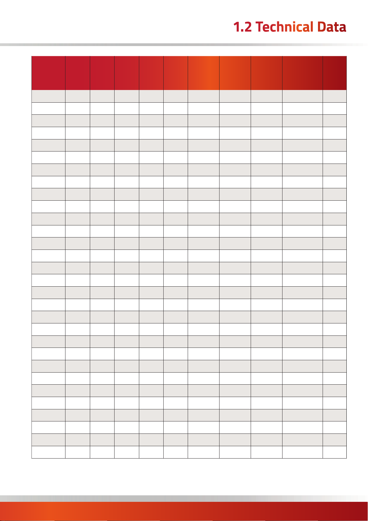
1.2 Technical Data
Model
PQ-A1A010
PQ-A1A015
PQ-A1A020
PQ-A1B020
PQ-A1B030
PQ-A1B040
PQ-A1C030
PQ-A1C045
PQ-A1C060
PQ-A1J020
PQ-A1J030
PQ-A1J040
Body
Dimensions
(W x H x D)
Voltage
Lamps x
Power
Total
Power
Current
Per Phase
Current
Per Phase
Min Height
From Floor
Min Height
From
Ceiling
Min Distance
From
Side Wall
v kW kW V A m m m mm Kg
230 1 × 1.0 1.0 1 4.3 2.0 0.15 1.0 422 × 255 × 110 3.0
230 1 × 1.5 1.5 1 6.5 2.0 0.15 1.0 422 × 255 × 110 3.0
230 1 × 2.0 2.0 1 8.7 2.0 0.15 1.0 422 × 255 × 110 3.0
230 2 × 1.0 2.0 1 8.7 2.0 0.5 1.5 422 × 390 × 110 4.0
230 2 × 1.5 3.0 1 13.0 2.0 0.5 1.5 422 × 390 × 110 4.0
230 2 × 2.0 4.0 1 17.4 2.5 0.5 1.5 422 × 390 × 110 4.0
230 3 × 1.0 3.0 1 13.0 2.0 0.5 1.5 422 × 525 × 110 5.0
230 3 × 1.5 4.5 1 19.6 2.5 0.5 1.5 422 × 525 × 110 5.0
230 3 × 2.0 6.0 1 26.0 3.0 0.5 1.5 422 × 525 × 110 5.0
230 2 × 1.0 2.0 1 8.7 2.5 0.15 1.0 857 × 255 × 110 6.0
230 2 × 1.5 3.0 1 13.0 2.5 0.15 1.0 857 × 255 × 110 6.0
230 2 × 2.0 4.0 1 17.4 2.5 0.15 1.0 857 × 255 × 110 6.0
Weight
Without
Guard
PK-A1K030
PK-A1K045
PK-A1K060
PQ-A3C030
PQ-A3C045
PQ-A3C060
PQ-A3E060
PQ-A3E090
PQ-A3E120
PQ-A3F090
PQ-A3F135
PQ-A3F180
PQ-A3K030
PQ-A3K045
PQ-A3K060
230 3 × 1.0 3.0 1 13.0 2.5 0.15 1.5 1282 × 255 × 110 8.0
230 3 × 1.5 4.5 1 19.6 2.5 0.15 1.5 1282 × 255 × 110 8.0
230 3 × 2.0 6.0 1 26.0 3.0 0.15 1.5 1282 × 255 × 110 8.0
400 3 × 1.0 3.0 3* 4.3 2.0 0.5 1.5 422 × 525 × 110 5.5
400 3 × 1.5 4.5 3* 6.5 2.5 0.5 1.5 422 × 525 × 110 5.5
400 3 × 2.0 6.0 3* 8.7 3.0 0.5 1.5 422 × 525 × 110 5.5
400 6 × 1.0 6.0 3* 8.7 3.0 0.5 1.5 857 × 630 × 110 12.0
400 6 × 1.5 9.0 3* 13.0 4.0 0.5 1.5 857 × 630 × 110 12.0
400 6 × 2.0 12.0 3* 17.4 4.5 0.5 1.5 857 × 630 × 110 12.0
400 9 × 1.0 9.0 3* 13.0 4.0 0.5 1.5 1282 × 630 × 110 20.0
400 9 × 1.5 13.5 3* 19.6 5.0 0.5 1.5 1282 × 630 × 110 20.0
400 3 × 2.0 18.0 3* 26.1 6.0 0.5 1.5 1282 × 630 × 110 20.0
400 3 × 1.0 3.0 3* 4.3 2.5 0.5 1.5 1282 × 255 × 110 8.0
400 3 × 1.5 4.5 3* 6.5 2.5 0.5 1.5 1282 × 255 × 110 8.0
400 3 × 2.0 6.0 3* 8.7 3.0 0.5 1.5 1282 × 255 × 110 8.0
PQ-A3L060
PQ-A3L090
PQ-A3L120
* Star connection with neutral star point to balance load.
400 6 × 1.0 6.0 3* 8.7 3.0 0.5 1.5 1282 × 441 × 110 17.0
400 6 × 1.5 9.0 3* 13.0 4.0 0.5 1.5 1282 × 441 × 110 17.0
400 6 × 2.0 12.0 3* 17.4 4.5 0.5 1.5 1282 × 441 × 110 17.0
PQ-A Range Users, Installation & Servicing Instructions Doc Ref M308 issue 1.1 May 2019.
page no. 9 of 16
Page 10
2.1 Fitting the Unit
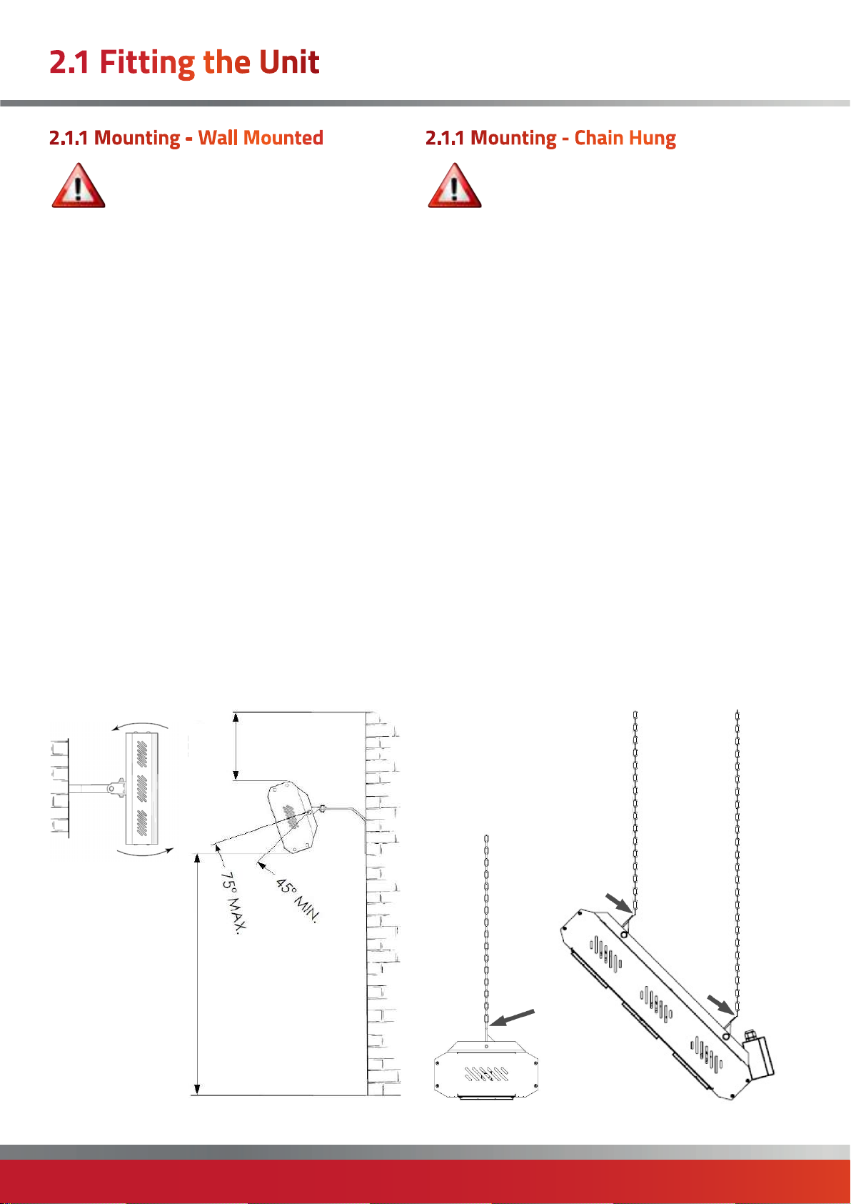
2.1.1 Mounting - Wall Mounted
Warning: Switch off/unplug the heater from
the mains supply when mounting or adjusting
the heater position.
• The heater must be mounted in such a way that the
halogen lamp does not slant more than 4° from the
horizontal, when viewed from the front.
• The heater is suitable for installation only on a normally
non-flammable surface. Observe the minimum safe
distance between the heater body and inflammable
surfaces when mounting.
• Refer to Section 1.2 for the recommended mounting
height for the heater.
• Keep out of the reach of children.
1. Separate the heater from the mounting bracket by
loosening the two nuts at the rear of the heater.
2. Securely fasten the bracket to the mounting surface
using the fixing holes in the bracket.
3. Replace the heater on the bracket using the nut and
bolt supplied and fix in the required angular position by
tightening the fixing bolt on the bracket. See diagram
below.
2.1.1 Mounting - Chain Hung
Warning: : Switch off/unplug the heater from
the mains supply when mounting or adjusting
the heater position.
• The heater is suitable for installation on chains that are
suitably fixed to a structure sufficient to hold the weight of
the heater.
• Observe the minimum safe distance between the heater
body and inflammable surfaces when mounting.
• Refer to Section 1.2 for the recommended positioning
of the heater with regards to minimum distances.
• Do not install the heater in a corner! If installing near
a corner, always ensure minimum side wall distance is
adhered to.
• Always allow the heater to cool before attempting to
reposition/move. Never attempt to move the heater while
it is switched on!
1. When chain hung, ensure chains are of adequate size
and securely fixed to support the weight of the heater.
2. Fix the heater assembly to the chains via the holes in
the body brackets if intending to face directly down as
shown below. On units having channel brackets, attach the
chains to the adjustable brackets as shown below.
PLAN VIEW
SIDE VIEW
SEE
SECTION 1.2
SEE SECTION 1.2
• Ensure the supply cord does not rest on the heater.
page no. 10 of 16
PQ-A Range Users, Installation & Servicing Instructions Doc Ref M308 issue 1.1 May 2019.
Page 11
2.1 Fitting the Unit
2.1.3. Electrical Connections
Warning: This appliance must be earthed!
Warning: If the supply cord is damaged, it
must be replaced by the manufacturer, its
service agent or similarly qualified persons in
order to avoid a hazard.
CAUTION: Please observe the minimum safe
distance between the heater body and any
inflammable surfaces.
CAUTION: All installations must be in
accordance with the latest electrical safety
regulations. If in any doubt, please consult a
suitably qualified electrician.
Note: When hard wiring, a large double pole
switch with a 3.0mm contact disconnection
should be fitted.
Note: We recommend using a RCD where
applicable.
Note: All installations must be in accordance
with the latest I.E.E safety regulations or
equivalent. If in any doubt, please consult a
suitably qualified electrician.
• Single length lamps - models PQ-A1A010, PQ-A1A015,
PQ-A1A020, PQ-A1B020, PQ-A1B030, PQ-A1B040,
PQ-A1C030, PQ-A1C045 and PQ-A1C060 are fitted with
2.0 meters of supply cord for hard wiring therefore it is
unnecessary to remove the terminal cover plate in order
to carry out normal installation of these models.
The wire which is coloured green and yellow must be
connected to the terminal in the plug which is marked with
the letter E, or with the earth symbol, or coloured green, or
green and yellow.
The wire which is coloured blue must be connected to the
terminal marked N or coloured black.
The wire which is coloured brown must be connected to
the terminal marked L or coloured red.
• All unwired versions should be installed by a suitably
qualified electrician, following the instructions herewith.
• Heat resisting cable must be used.
• We recommend using a RCD where applicable. If self
wiring, a large double pole switch with a 3mm contact
disconnection should be fitted.
• If the supply cord becomes damaged, it must be replaced
by the manufacturer, its service agent or a similar qualified
person in order to avoid a hazard.
• For industrial installations, the units must be supplied
via double pole miniature circuit breakers (MCB) with
instantaneous coefficients in the range 7 to 10 with a
separation of at least 3mm between contacts.
Refer to section 1.2 for MCB ratings.
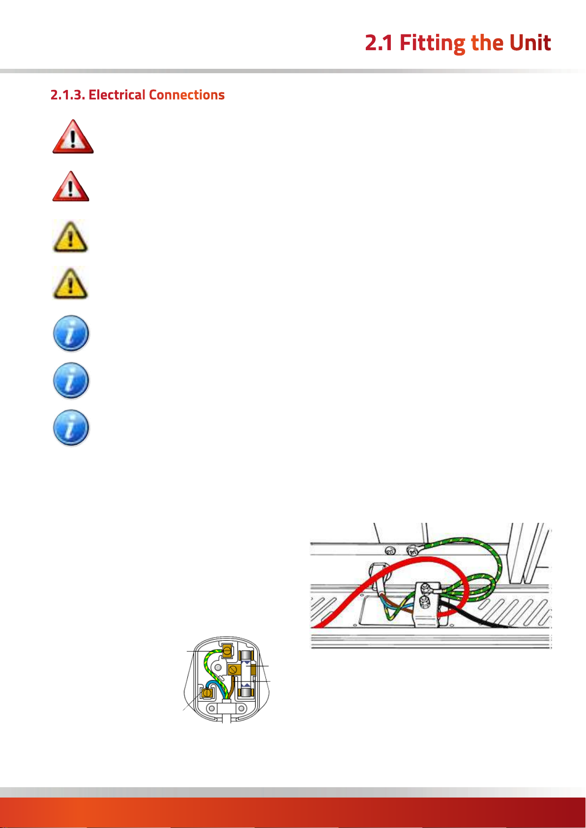
1. Remove cover from terminal box mounted at the rear of
the heater.
2. Feed the supply cable through the strain relief bush (not
supplied) and connect to the terminal block and earth stud
(as shown below).
A domestic 13 Amp socket is used for the power supply,
proceed as follows for plug connections. Note: A domestic
plug/socket is only suitable for models PQ-A1A010, PQA1A015, PQ-A1A020 and PQ-A1B020.
The wires in the mains lead are coloured in accordance
with the following code:
EARTH
Green and yellow: Earth,
Blue: Neutral,
Brown: Live.
NEUTRAL
• Since the colours of the wires in the mains lead of
this appliance may not correspond with the markings
identifying the terminals in the plug, proceed as follows:
PQ-A Range Users, Installation & Servicing Instructions Doc Ref M308 issue 1.1 May 2019.
FUSE
LIVE
page no. 11 of 16
Page 12
2.2 Maintenance
Note: It is very important that the
replacement lamp is exactly the same as the
one the heater was supplied with.
Failure to fit the exact same type could cause the heater
to fail or even become dangerous especially when used in
an outdoor environment.
Please contact Powrmatic Limited to purchase your
replacement lamp and state the model
number of the heater you wish
to fit the lamp to.
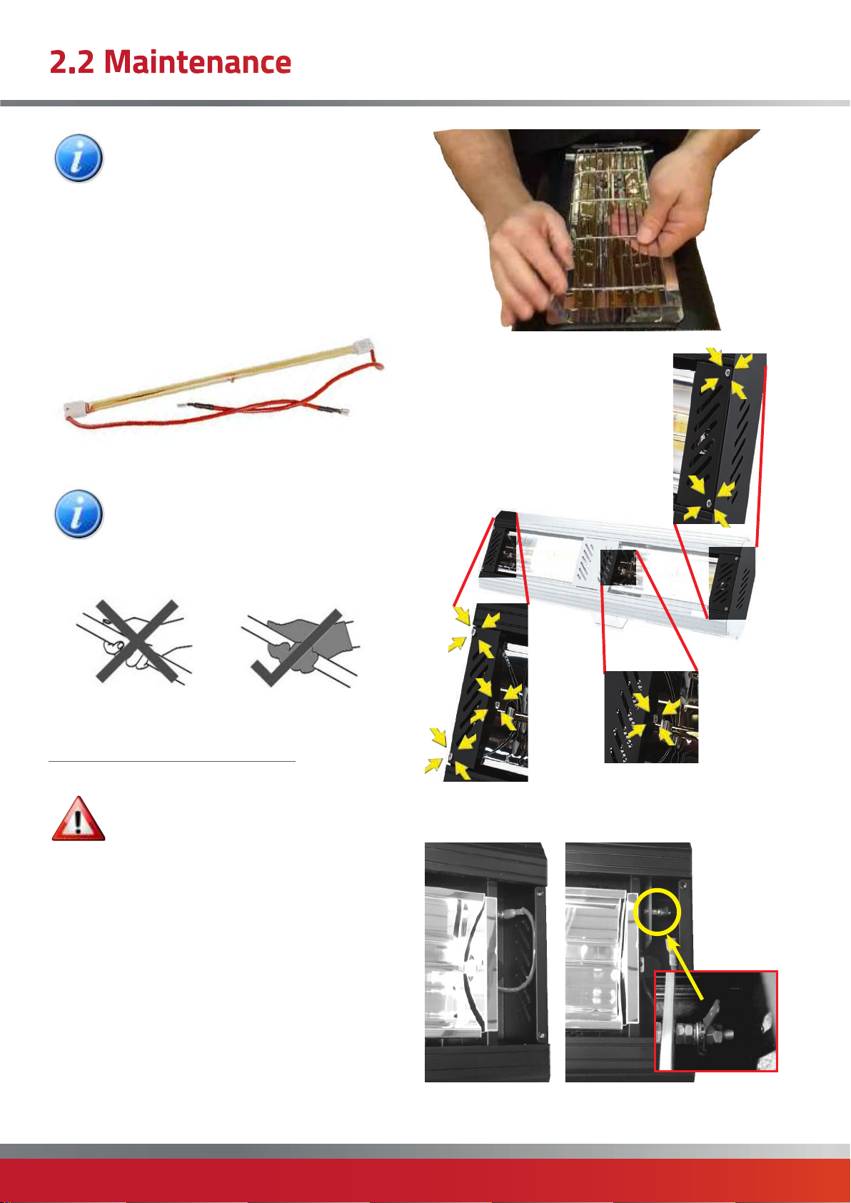
3. Remove either the three screws from
both front side covers on smaller
models, or remove the screws from
both sides the middle cover(s) on
longer models by as shown below.
Note: Your new lamp(s) should NOT be handled
with bare hands. Remove finger marks with a
soft cloth and methylated spirits or rubbing
alcohol. Finger marks will burn into the lamps
quartz glass causing premature failure.
2.2.1. REPLACING A LAMP
Warning: Unplug/switch off from the
mains power to the heater power before any
attempts are made to replace the lamp.
Contact your service agent for the correct replacement
lamp quoting model type and rating from rating label.
It is important that you read through the lamp
replacement procedure before commencing.
4. Locate the lamp wire by the terminal and release from
tab. Repeat at other end.
1. Disconnect the power supply to the heater.
2. Remove guard (where fitted) by flexing one end and
releasing from it’s locating holes on the lamp to be
replaced.
page no. 12 of 16
PQ-A Range Users, Installation & Servicing Instructions Doc Ref M308 issue 1.1 May 2019.
Page 13
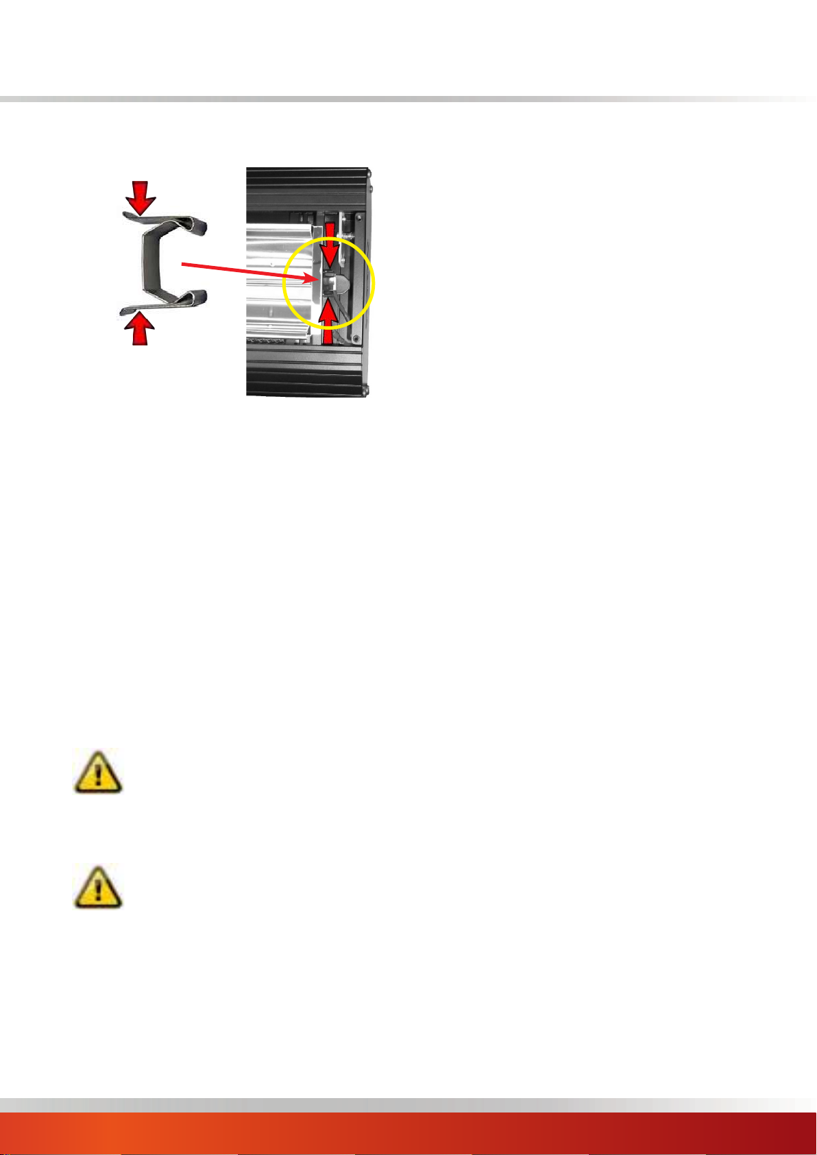
5. Remove the lamp holding clips by squeezing the clip
together and lifting away as shown.
6. Slide the lamp out through the extrusion feeding one
way first with the wire and then the opposite way to take
out and remove.
Take care not to scratch the reflector surface.
7. Refit the new lamp.
Take care not to mark the reflector or touch the new lamp
with the hands (see caution).
8. Replace the lamp holding clips. Make sure they are
firmly in place over the white ceramic ends of the lamp.
9. Refit the male and female connectors by fully pushing
together. Cover and refit the black sleeve.
10. Replace the front side and or middle covers in reverse
order and then refit the wire guard(s) if originally fitted.
CAUTION:. Do not handle lamp with bare
hands.
Remove finger marks with a soft cloth and
methylated spirit or alcohol.
Finger marks will burn into quartz causing
premature lamp failure.
CAUTION:
Outer casing can reach high temperatures.
PQ-A Range Users, Installation & Servicing Instructions Doc Ref M308 issue 1.1 May 2019.
page no. 13 of 16
Page 14
Notes:
page no. 14 of 16
PQ-A Range Users, Installation & Servicing Instructions Doc Ref M308 issue 1.1 May 2019.
Page 15
Notes:
PQ-A Range Users, Installation & Servicing Instructions Doc Ref M308 issue 1.1 May 2019.
page no. 15 of 16
Page 16
www.powrmatic.co.uk
Getting In Touch
Powrmatic Limited
Hort Bridge, Ilminster
Somerset
Stamm International HQ
TA19 9PS
tel: +44 (0) 1460 53535
Stamm International Corporation
fax: +44 (0) 1460 52341
PO Box 1929
e-mail: [email protected]
Fort Lee, NJ 07024
web: www.powrmatic.co.uk
Tel: 201-947-1700
Fax: 201-947-9662
E-mail: stamminc@pobox.com
More information is available from our website by scanning the following QR code.
Powrmatic Ireland
45 Broomhill Close
Tallaght
Dublin 24
tel: +353 (0) 1452 1533
fax: +353 (0) 1452 1764
e-mail: [email protected]
web: www.powrmatic.ie
Powrmatic pursues a policy of continues improvement in both design and performance of its products and therefore reserves the right to change, amend or
vary specifications without notice. Whilst the details contained herein are believed to be correct they do not form the basis of any contract and interested
parties should contact the Company to confirm whether any material alterations have been made since publication of this brochure.
page no. 16 of 16
ICOM
Energy Association
PQ-A Range Users, Installation & Servicing Instructions Doc Ref M308 issue 1.1 May 2019.
EURO-AIR
QUALITY
 Loading...