

Page 1
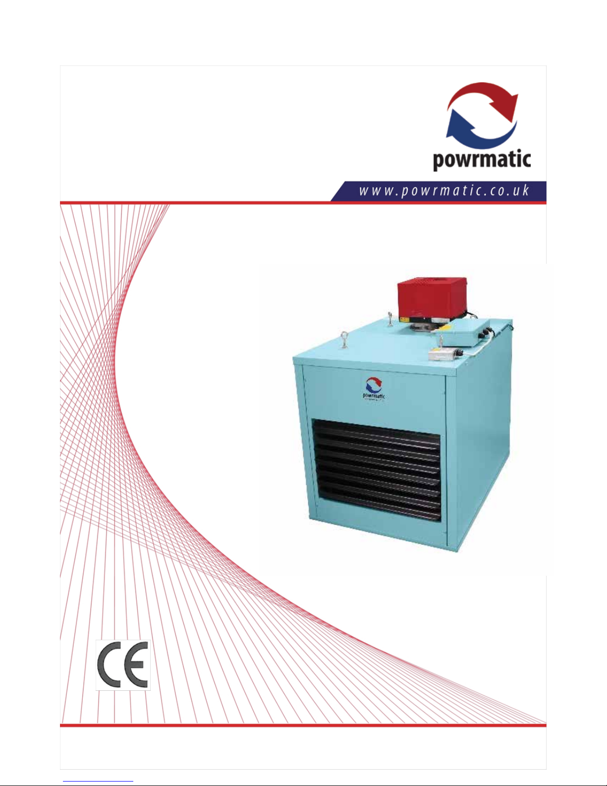
OUH Suspended Oil Unit Heater
Industrial & Commercial Heating Systems.
Issue 5.1 September 2015
Users, Installaon and
Servicing Instrucons
WARNING: THIS APPLIANCE MUST BE EARTHED
H E A T I N G / / V E N T I L A T I O N / / A I R C O N D I T I O N I N G
Page 2
powrmatic
Certificate of Guarantee
Dear Customer
This is to certify that this heater is guaranteed for two years parts and one year labour
from the date of original commissioning. The heater must be commissioned within 4
weeks of installation.
To make a claim
In the first instance you must contact your appliance supplier, or installer and provide:-
1. The appliance type and serial number.
2. The original commissioning documentat
ion.
3. As much detail as possible on the fault.
Your supplier, of installer, will then contact Powrmatic to make a guarantee claim on
your behalf.
Conditions of Guarantee
1. The heater must have been installed by a competent regognised instraller, and in
accordance with the manufactures instructions, building regulations and local
regulations.
2. The heater has been professionally commissioned
, within 4 weeks of installation,
and a copy of the Commissioning Sheet returned to Powrmatic.
3. The heater has been maintained on a yearly basis by a competent servicing
company.
4. The heater has been used in accordance with the manufactures instructions.
5. The correct specification fuel has been used.
6. No unauthorised repairs of modifications have been made.
7. Powrmatic ‘General Conditi
ons of Sales’ have been observed.
8. Except for the obligation of Powrmatic Ltd to perform warranty repairs during the
guarantee period Powrmatic will not be liable in repect of any claim for direct or
indirect consequential losses, including loss of profits or increased cost arising from
loss of use of the heater, or any event arising there from.
Exclusions
1. Gaskets and fan belts are not included in the guarantee.
----------------------------------------------------
Powrmatic Ltd, Hort Bridge, Ilminster, Somerset, TA19 9PS
Tel:01460 53535 Fax: 01460 52341
Web: www.powrmatic.co.uk e-mail service@powrmatic.co.uk
Important: This certificate must
be kept with the appliance
Failure to provide a copy of the commissioning sheet invalidates the heater waranty
Installer
Date :_____________ Signed ____________________________________________Installer
Commissioned
Date :_____________ Signed _______________________________Commissioning Engineer
Page 2 OUH Range Users, Instrucons & Service Instrucons Issue 5.1 September 2015
Page 3

OUH Range Users, Instrucons & Service Instrucons Issue 5.1 September 2015 Page 3
Dear Customer - thank you for choosing Powrmac.
We appreciate you buying one of our high quality products and know that you have made the best
choice. By choosing Powrmac, you are invesng in UK manufacturing & its workforce. We pride
ourselves by manufacturing products that provide clean, comfortable and safe working environments worldwide together with the personal & professional service and back-up you deserve. If you
have any quesons or concerns regarding this product, please contact our Technical Support Team by
calling 01460 53535.
Users, Installaon and Servicing Instrucons
CONTENTS
Title Secon Contents Page
User Instrucons 4
Pre Installaon 1.1 Introducon 5
1.2 Technical Data - Size Data 6
1.3 General Requirements 8
Installaon 2.1 Fing the unit 11
2.2 Air Distribuon 12
2.3 Commissioning and Tesng 13
Servicing 3.1 Servicing 14
Data 4.1 Short List of Parts 15
Figure Title Page
1. Limit Thermostat 15
Table Title ` Page
1. Dimensions 7
2. Specications 7
3. Electrical Loadings 1ph 8
4. Burner Settings - 35sec Oil 8
Page 4
Page 4 OUH Range Users, Instrucons & Service Instrucons Issue 5.1 September 2015
A) Checks before lighting the Air
Heater
The following preliminary checks should be made before
lighting the heater(s)
a) Ensure that the ELECTRICAL supply to the heater is
switched OFF.
b) Check that all warm air delivery outlets are open.
c) Check that the thermostat is set at MAX.
d) Check that the clock control is set to an ON period.
e) Check that any other controls are calling for heat.
f) Ensure that the Summer/Winter switch is in the Winter
position.
g) Check that the overheat reset button has not operated.
B) Lighting the Air Heater
NOTE: If it is not possible to light the heater after
2/3 attempts contact your installer.
1. Switch on the electrical supply at the isolator.
2. Press the limit interlock reset switch on the control box
of the heater. (Note: This step is not performed again
unless there is an interruption in the electrical supply to
the heater).
3. The burner air fan will run and after a pre purge period
of approximately 30 seconds the ignition spark will be
generated and the oil valve opened.
The main burner will then start.
NOTE: If the main burner fails to light the burner
will go to lockout and the lockout indicator / reset
button on the burner control box will be illuminated. To restart the burner push the lockout reset
button. Additional, more easily accessible,
controls may be fitted that mimic the lockout
indicator and reset button functions.
If the unit will not light after four or five attempts
then shut down the unit and call in a service engineer.
C) To Shut Down the Air Heater
1. For Short Periods:
Turn the room thermostat to the OFF or lowest setting.
2. For Long Periods:
Turn the room thermostat to the OFF or lowest setting.
Wait approximately 4-5 minutes for the main air fan of the
heater to stop running and the turn off the oil supplies and
electric supplies to the heater.
D) Description of Operation
Important: All heaters must be controlled by the
fitted external controls and not by use of the main
switch in the electrical supply to the heater.
The burner start up sequence will commence when the
controls
e.g. Timeclock, room thermostat etc. call for heat. The
burner air fan will run and after a pre purge period the
burner will light.
Approximately 2/3 minutes after the burner lights the
heater fan will automatically start. When the external
controls are satisfied the burner will be turned off and
approximately 4/5 minutes later the heater fan will automatically stop.
D.1) Summer / Winter Modes
Certain types of external controls will provide for two
modes of operation i.e.
Summer: The heater fan alone will run at the dictate of the
external controls to provide air movement.
Winter: The heater will operate normally.
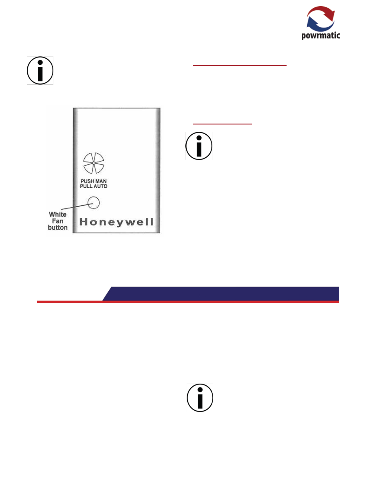
E) Fan and Limit Control
The fan and limit controls are mounted on the top of the
air heater.
1. Main Air Fan MAN / Auto
When the white button (Refer to Figure following) is
pushed in the fan will run continuously i.e not controlled
by any external controls e.g. Timeclock. When the white
button is pulled out the fan will start and stop automatically in conjunction with the burner. See Section 2.
2. Limit Thermostat
This operates if high temperatures within the heater are
detected, the burners are turned off and a red indicator
light on the front of the heater is illuminated. The fault
condition must be identified and rectified and the thermostat manually reset.
When the unit has cooled push the reset switch on the
front of the heater to reset the limit thermostat interlock
relay, the red indicator light will go out and the unit is operational again.
Note: The limit thermostat(s) can only be reset
once the unit has cooled down.
Unless the cause of the fault condition is readily
obvious, for example a power cut whilst the
heater was operating, a service engineer should
be contacted.
Users Instructions
Page 5
1.1 Introduction
The Powrmatic OUH Range is a range of oil fired forced
draught, closed flue, fanned circulation air heaters having
an output range of 20kW to 60kW .
The heaters are designed for suspension from suitable
roof points, or alternatively mounted on purpose designed
wall brackets, and are intended for heating commercial or
industrial premises.
The OUH-F has an axial type fan assembly fitted at the
rear of each heater to circulate the air being heated
across the combined combustion chamber/ heat
exchanger. A centrifugal fan variation is presented in the
OUH-C range for ducted applications. The OUH-D range,
in having no fan fitted, allows for ducted use where the air
moving unit is remote from the heater.
All units are fired with a forced draught packaged oil
burner complete with all necessary safety controls. Each
air heater must be connected to an individual closed flue
system only.
Fuel Types
All units are supplied as standard for use with 35sec fuel
and can be supplied for use with 28sec fuel as an option.
In accordance with guidelines from our burner supplier,
Riello, the burners fitted to Powrmatic oil-fired heaters are
suitable for fuels with a bio content of up to 10% only.
For fuels with a bio content of more than 10%, please
consult our Technical Department.
IMPORTANT
Service and Maintenance Engineers shall ensure
that replacement items are fitted, adjusted and
set in accordance with the data and detail set out
in these instructions. If in doubt consult P o w r matic Technical Department.
OUH Range Users, Instrucons & Service Instrucons Issue 5.1 September 2015 Page 5
Note: The limit thermostat interlock relay will
require resetting after loss of the electrical supply
to the heater regardless of whether the limit
thermostat has operated.
Limit Thermostat
F) Fan and Limit Control
Regular servicing is essential to maintain efficient, reliable
and safe operation of the heater. Users are strongly
recommended to have the heater serviced by a qualified
person at least annually and preferably at the end of the
heating season.
G) IMPORTANT
Free access must be maintained to and around
the heater for servicing purposes and the air
supply to the heater must not be restricted in any
way. Combustible materials must not be stored
adjacent to the heater.
All Powrmatic OUH heaters use oil and electricity
to power them, they may also contain moving
parts such as pulley belts.
It would be hazardous to tamper with or attempt
to service unless you are a competent person in
the field of Oil and Electrical work.
If you have any safety questions reference the
servicing and installation of any of our heaters
please do not hesitate to contact our head office
for expert advice.
Your safety is paramount to us.
Page 6

Page 6 OUH Range Users, Instrucons & Service Instrucons Issue 5.1 September 2015
1.2 Technical Data
OUH20/F
OUH20/C
OUH30, 45 & 60/F
Rear View
EF F
D
A K
Side View
B
C
M
Front View
Rear View
L50mm
Side View
J
H
G
Front View
Rear View
E F
D
A K
Side View
B
C
M
Front View
Page 7

OUH Range Users, Instrucons & Service Instrucons Issue 5.1 September 2015 Page 7
OUH30, 45 & 60/C
Table 1. Dimensions
Note: D is the norminal flue diameter.
Table 2. - Specifications
Rear View
50mm L
Side View
J
H
G
Front View
Model
OUH 20
555 610 100 465 101 549
410
370340
85
OUH 30
270
Type
668
N/A N/A
780 847 125 490 276 490
494
270975
636 418
131
N/A N/A
N/A
N/A
N/A
N/A
F
F
C
C
A
B
C
D
E
F
G
H
J
K
L
M
MAXIMUM
DUCT
RESISTANCE
MODEL
INPUT
(Net)
OUTPUT
kg
kW m³/s Pa kW
OUH20
21.92 20.0 0.5758
OUH 30
32.15 30.0 0.6847
OUH 45
49.40 45.0 1.0814
OUH 60
65.57 60.0 1.4072
N/A 0.040 53
140
0.373
91.5
N/A
0.130
126
187 1.100 142
N/A 0.300 126
100 1.100 142
N/A 0.760 126
50 1.100 142
F
C
F
C
F
C
F
C
HIGH FIRE
AIR
VOLUME
FAN
MOTOR
WEIGHT
NOISE
LEVEL
dB(A) @ 3m
N/A
N/A
N/A
N/A
46
54
52
53
THROW
8.5
16.1
25.3
34.1
N/A
N/A
N/A
N/A
lt/h
2.17
3.19
4.89
6.51
FUEL
INPUT
OUH 45 780 847 125 490 276 490
494
270975
636 418
143
N/A N/A N/A
N/A
F
C
OUH 60 780 847 125 490 276 490
494
270975
636 418
165
N/A N/A N/A
N/A
F
C
Page 8

Page 8 OUH Range Users, Instrucons & Service Instrucons Issue 5.1 September 2015
Table 3 - Electrical Loadings 1ph
Table 4 - Burner Settings - 35sec Oil - Net CV (i) = 42.69 Mj/kg
1.3 General Requirements
1.3.1. Related Documents
Installation of air heaters must be in accordance with the
relevant requirements of:
BS 5410: Part 2: 1978 Code of Practice for Oil Firing
Installations of 45kW and Above
The Building Regulations
The I.E.E. Regulations
It should also be in accordance with relevant requirements of the local authority and fire authority, in addition
the following British Standard Codes of Practice must be
observed CP.3 Ch IV Precautions Against Fire Part 2
Shops and Departmental Stores Part 3 Office Buildings.
OFTEC Technical Book 3: Domestic & Commercial
requirements for oil storage and supply equipment.
OFTEC Technical Book 4: Oil fired appliances & system
installation requirements.
OFTEC Easy Guides to non domestic oil feed pipes and
oil storage.
1.3.2 Location
The location chosen for the air heater must permit the
provision of a satisfactory flue system and an adequate air
supply. The location must also facilitate ease of servicing
and satisfactory air circulation around the heater.
The air heater must be installed strictly in accordance with
any fire regulations or insurance company's requirements
appertaining to the area in which the heater is located,
particularly where special risks are involved such as areas
where petrol vehicles are housed, cellulose spraying
areas, and wood working departments etc.
The air heater must be installed either:
(a) suspended by chains or straps of adequate strength to
safely carry the weight of the unit and ancillary equipment
or
(b) On specifically designed cantilever brackets from a
non-combustible wall or
(c) On a level non-combustible surface which is capable
of adequately supporting the weight of the air heater and
any ancillary equipment.
The heater must not be installed in conditions for which it
is not specifically designed e.g. highly corrosive atmospheres, vitiated atmospheres, or where adverse wind
conditions may be experienced. Where the location of the
heater is such that it might suffer external mechanical
damage e.g. from overhead cranes, fork lift trucks etc. it
must be suitably protected. Any ducting should be kept as
short and direct as possible having regard to the distribution of the heated air.
/F Models /C Models
MODEL
PLATE
AMPS
(A)
START
AMPS
(A)
RUN
AMPS
(A)
FUSE
RATING
(A)
OUH 20
2
OUH 30
0.18 0.34 0.16 3.3 6.5 4.2
1.05 0.33 9.8 18.0 7.2
OUH 45
2.40 1.20 9.8 18.0 7.2
5
NOMINAL
MOTOR
R.P.M.
PLATE
AMPS
(A)
START
AMPS
(A)
RUN
AMPS
(A)
FUSE
RATING
(A)
OUH 60
5.90 3.00
0.60
3.30
1.25
9.8 18.0 7.2
900
1230
10
900
Riello Burners
Nozzle Pump Head Setting Combustion Nominal
Model Type Make Size Angle Type Pressure No. Postion Air Setting CO
2
%
US Gal ° bar
OUH 20 3GB Danfoss 0.50 60 S 9.5 N/A Fixed 2.0 12.5
OUH 30 G10 Danfoss 0.60 45 S 14.3 1.0 N/A 1.5 12.8
OUH 45 G10 Danfoss 1.00 45 S 12.2 3.0 N/A 2.0 12.0
OUH 60 G10 Danfoss 1.25 45 S 15.6 3.0 N/A 5.0 12.0
950
910
1370
NOMINAL
MOTOR
R.P.M.
5
3
Page 9

OUH Range Users, Instrucons & Service Instrucons Issue 5.1 September 2015 Page 9
Any combustible material adjacent to the heater and flue
systems must be so placed as to ensure that its temperature does not exceed 65°C (150°F).
1.3.3 Main Storage Tank and fittings
Construction and installation should be in accordance
with:
(a) BS 5410 Part 2 Section 6
(b) BS 799 Part 5
(c) BS 1563
The latter three standards apply to cast iron sectional,
mild steel sectional, and mild steel welded tanks respectively and therefore must be applied appropriately.
1.3.4 Service Tanks and fittings
1.3.4.1 Construction
These should be designed and constructed in accordance with BS 799 Part 5
1.3.4.2. Installation
The installation should be in accordance with:- BS 5410
Part 2.
In addition the service tank installation must comply with
local regulations and by-laws and with the requirements
of insurance companies
1.3.5 One Pipe System (Storage to
burner)
1.3.5.1 General
Refer also to the detail provided in the burner handbook
regarding pipe sizing. These must be generally in accordance with B S 799 Part 3 and BS 5410 Part 2.
Particular attention is drawn to the following:
a) Pipe jointing compounds must be capable of withstanding the solvent action of the fuel oil under all operating
temperatures and pressures. Jointing compounds
containing oil shall not be used. Hemp and other fibrous
materials shall not be used as packing for screwed joints.
b) Soft solder copper tube fittings and galvanised pipes
and fittings must not be used.
c) Oil lines must be completely air-tight.
d) The pump suction must not exceed a maximum of 0.4
bar (30cm Hg). Beyond this limit gas may be released
from the oil.
1.3.5.2 Single Pipe System - Gravity
Feed
Warning: The burners are supplied adjusted for a single
pipe system. If the burner is to be used on a twin pipe
system the Internal bypass plug of the burner oil pump
must be fitted. Refer to the burner instruction booklet.
Ideally the return pipe should terminate within the oil tank
at the same level as the suction line, both being below the
minimum oil level.
1.3.6 Fire Valve
It is recommended that the fire valves should be installed
as follows:
1. Main storage to service tank supply (if applicable)
2. Main storage to burner supply
3. Service tank to burner supply (if applicable)
Fire valves should be installed generally in accordance
with the requirements of BS 799: Part 5. The fire valve
should be situated in an easily accessible position as near
the tank as possible and where practicable within the
boundary of the tank chamber or catchpit retaining wall.
1.3.7 Flue System
The flue system should generally be in accordance with
BS 5410 Part 2.
Materials used for the flue system should be mechanically
robust, resistant to internal and external corrosion,
non-combustible and durable under the conditions to
which they are likely to be subjected. Prevention of
condensation within the flue should be an important factor
in the design of the flue system. In order to minimise
condensation the use of double walled flue pipe or insulation is recommended.
Where condensation in the flue is unavoidable, or rain
ingress is possible, provision must be made for a condensate drain connected to a suitable drain or gully. The
condensation pipe from the flue to the disposal point
should be of non-corrodible material of not less than
22mm (¾ in) size.
Facilities should be provided for disconnecting the flue
pipe from the air heater for inspection and servicing
purposes. Bends with removable covers should be fitted
for inspection and cleaning purposes where considered
appropriate.
The flue should terminate in a freely exposed position and
must be situated such that products of combustion do not
enter any opening in a building in such concentration as
Page 10

Page 10 OUH Range Users, Instrucons & Service Instrucons Issue 5.1 September 2015
to constitute a health hazard.
1.3.8 Combustion & Ventilation Air
Supply
Where the air heater is to be installed in the space to be
heated it requires the space containing it to have a permanent air vent direct to outside air. The air vent should have
negligible resistance and must not be sited in any position
where it is likely to be easily blocked or flooded, neither
should it be positioned adjacent to an extraction system
carrying flammable vapour.
The air supply requirement that follows is related to the
maximum rated heat input of the heater, or heaters if more
than one is installed in the same space.
Total Input Rating Air Vent Area
of Air Heaters (Air direct-from outside)
Up to 60kW 4.5 cm²/kW in excess of 7kW
From 60kW up to 730kW 4.5 cm²/kW
Where the air heater is to be installed in a plant room, the
heater requires the plant room housing it to have permanent air vents communicating directly with the outside air,
at high and low level. Where communication with the
outside air is possible only by means of high level air
vents, ducting down to floor level for the lower vents
should be used. Air vents should have negligible resistance and must not be sited in any position where they are
likely to be easily blocked or flooded, neither should they
be positioned adjacent to any extraction system carrying
flammable vapour.
Grilles or louvers should be so designed that high velocity
air streams do not occur within the plant room.
The air supply requirements stated below are related to
the maximum rated heat input of the air heater(s). The
minimum free area requirements of the air vents is given
below.
Total Input Rating Position of Air Vent Areas
of Air Heater(s) Vents (Air direct from
outside)
Up to 730kW High Level 4.5cm²/kW
Low Level 9.0 cm²/kW
1.3.9 Air Distribution System
Where single OUH units are required to cover a large floor
area, and in buildings with high roof or ceiling heights
Calecon thermal economiser units should be fitted to
ensure even heat distribution and minimise stratification.
Care should be taken to avoid impeding the air throw with
racking, partitions, plant or machinery etc. Various outlet
configurations are available as optional extras to modify
the air throw pattern to suit particular site conditions.
For ducted units all delivery and return air ducts, including
air filters, jointing and any insulation or lining must be
constructed entirely of materials which will not contribute
to a fire, are of adequate strength and dimensionally
stable for the maximum internal and external temperatures to which they are to be exposed during commissioning and normal operation.
Where inter-joist spaces are used as duct routes they
should be suitably lined with a fire-resisting material.
A full and unobstructed return air path to the air heater(s)
must be provided.
If the air heater(s) is installed in a plant room the return air
intake(s) and the warm air outlet(s) from the heater(s)
must be fully ducted, into and out of the plant room to
avoid interference with the operation of the heater.
The openings in the structure of the plant room through
which the ducting passes must be fire stopped.
Care must be taken to ensure that return-air intakes are
kept clear of sources of smells and fumes, and where
there is any possibility of pollution of the air by dust, shavings etc., precautions must be taken to prevent contamination.
If necessary suitable barrier rails should be provided to
prevent any combustible material being placed within
900mm of the outlets.
1.3.10 Electrical Supply
Wiring external to the air heater must be installed in accordance with the I.E.E. Regulations for Electrical Installations and any local regulations which apply.
All standard heaters are supplied by 230V - 1ph, 50Hz.
The method of connection to the main electricity supply
must:-
- facilitate the complete electrical isolation of the unit(s)
- be in a readily accessible position adjacent to the unit(s)
- serve only the unit(s)
- have a contact separation of at least 3mm in all poles.
See the accompanying wiring diagram for the heater
electrical connections
OUH units can also be supplied for 400V 3N, 50Hz.
Page 11

OUH Range Users, Instrucons & Service Instrucons Issue 5.1 September 2015 Page 11
2.1 Fitting the Unit
2.1.1 General
The air heater will be delivered to site pallet mounted and
protected by plastic sheeting.
Whichever method of mounting the air heater is used the
following minimum clearances for installation and servicing must be observed:
Right-hand side (looking at front of heater) 0.5m
Left-hand side (looking at front of heater) 0.5m
Top of burner to ceiling 1.0m
Rear of heater to nearest wall 0.4m
In order to achieve the desired performance levels it is
recommended that the installation height (floor level to
base of unit) for OUH20 and OUH30 is between 2.5m
and 3.0m, and OUH45 and OUH60 is between 3.0m and
5.0m.
If the heater is to be base mounted it may be stood directly on the platform, provided it is of a suitable non-combustible material and does not extend past the front edge of
the heater.
For multi-heater installations the following minimum
distances between units must be observed.
Between units, side to side 3.0m
Between units, back to back 3.0m
2.1.2 Fitting the Air Heater
The air heater may be installed either:
(a) Suspended by steel chains, rods or straps.
(b) On specifically designed cantilever brackets from a
non-combustible wall.
(c) On a level non-combustible surface providing the
platform does not extend past the front edge of the heater.
Whatever method of installation is used it must be capable of adequately supporting the weight of the unit (See
Table 2) and allowance must be made for any ancillary
equipment. Before installing the heater any existing trusses, walls brackets etc. must be inspected to ensure they
are suitable. All supports should be protected against
corrosion.
If noise levels are of particular importance, the heater
should be isolated from the structure of the building by
installing it on suitable anti-vibration mountings.
In all such cases, and in addition, when the heater is
suspended it is essential that all oil, duct, electrical and
flue connections to the heater are made with flexible
connections to maintain continuity of connection. In the
case of the flue connection single wall stainless steel flue
is deemed to flex sufficiently to meet the requirements.
2.1.3 Connection of Air Heater(s) to
Flue System
The flue system connects directly into the flue socket on
the top (OUH20) or rear (OUH30 - 60) of the heater. The
socket is sized to accept standard sheet metal flue that is
secured in place using suitable fasteners.
The flue system must be fabricated with sockets facing
upwards and sound joints must be achieved by either:
(a) a close tolerance mechanical fit between sections, or
(b) the use of a suitable caulking string and cold caulking
compound.
2.1.3.1. General Requirements
In all cases the flue outlet socket must be connected via
an approved flue system to outside air. . If an offset is
required two sets of 45° bends may be used each set
being equivalent to 0.5m of flue length. The minimum flue
length (end of flue terminal to top of heater) shall not be
less than 2.0m.
All flue ducts must be supported independently of the air
heater.
The flue terminal must not be installed so as to be less
than:
- 300mm below an opening e.g. window, air brick etc.
- 200mm below eaves or gutter.
- 300mm from an internal or external corner.
- 1200mm from a surface facing the terminal.
- 1500mm vertically from another terminal on the same
wall.
- 300mm horizontally from another terminal on the same
wall.
- 2000mm from ground level.
2.1.4 Condensate Drainage
The design of the flue system should minimise the formation of condensation and long external runs should be
completed in twin wall insulated flue. Where condensate
and/or rain water ingress is envisaged to be a problem a
flue drain length or condensate drain tee that drains into a
gulley must be fitted.
Page 12

Page 12 OUH Range Users, Instrucons & Service Instrucons Issue 5.1 September 2015
2.1.5 Oil Connection
The oil pipework length and diameter should be in accordance with the information given in the burner instruction
booklet.
The pump suction should not exceed 0.4 bar.
The oil line must terminate not more than 450mm from the
burner with the final connection by the flexible hoses
supplied with the burner.
Because the burner is at high level it is recommended that
a non-return valve is fitted adjacent to the burner to
prevent oil draining back when the burner is not operating.
2.1.6 Electrical Connections
All units are fully prewired and only require final connection of the incoming mains supply and completion of the
control circuit (230V) via a room thermostat, time clock
etc.
All units must be earthed. The electrical supply must be
run to a point adjacent to the heater and be suitably terminated to provide an isolation point that will prevent remote
activation of the unit during servicing. See Table 3 (Page
3) to ascertain the electrical loading of the unit(s) so that
cables of adequate cross-sectional area are used for the
electrical installation. The length of the conductors
between the cord anchorage and the terminals must be
such that the current carrying conductors become taut
before the earth conductor if the cable or cord slips out of
the cord anchorage. All external controls must be of an
approved type.
See the wiring diagram in Section 8.
OUH/D models supplied less fan must be electrically
interlocked to the air movement system so that this is
started in the same manner as the air heater fan would be
viz. A connection from the heater terminal marked “Live
Main Fan” must be made to one side of the fan motor
contactor coil, the other side of the coil being connected to
Neutral. The fan motor electrical supply must be direct
and not taken from the internal wiring of the OUH heater.
2.2 Air Distribution System
2.2.1 General
OUH/C and OUH/D models are designed for use with duct
work to more precisely define the point of air delivery, and
/or provide ducted return air or ducted fresh air inlet. All
ducting must be independently supported of the air
heater.
Joints and seams of supply ducts and fittings must be
securely fastened and made airtight. If required the
ductwork should be insulated to reduce heat loss.
2.2.2 Noise Reduction
Ducting should be connected to the heater spigots via an
airtight flexible coupling of non-combustible material.
Before fitting the coupling it must be ensured that a
minimum clearance of approximately 15mm will be maintained between the ends of the ducting and the heater
spigots.
Sound attenuators may be fitted in inlet and outlet ducts to
reduce airborne fan noise. Materials used in outlet sound
attenuators must be capable of withstanding 100°C air
temperature without any deterioration.
2.2.3 Room Thermostat Siting
The room thermostat should be fitted at a point which will
be generally representative of the heated area as far as
temperature is concerned. Draughty areas, areas subjected to direct heat e.g. from the sun, and areas where the
air movement is relatively stagnant e.g. in recesses, are
all positions to be avoided.
The thermostat should be mounted about 1.5m from the
floor.
Any room thermostat, frost thermostat, time clock etc.
must be suitable for switching 230V, 5A and must be of the
'snap action' type to minimise contact bounce.
For electrical connections of external controls see the
wiring diagrams in Section 4.2.
Page 13

OUH Range Users, Instrucons & Service Instrucons Issue 5.1 September 2015 Page 13
2.3 Commissioning & Testing
2.3.1 Electrical Installation
Checks to ensure electrical safety must be carried out by
a qualified person.
2.3.2 Oil Installation
This should be commissioned generally in accordance
with BS 5410 Part 2 Section 59 Paragraphs 59.1.1.1 to
59.1.1.6
2.3.3 Air Distribution System
The system should be checked to ensure that the installation work has been carried out in accordance with the
design requirements.
Particular attention should be given to the correct arrangement of delivery ducts and registers, return air ducts and
grills and general adequacy of return air paths.
For OUH/C and OUH/D units ensure that the ductwork is
balanced so that the specified motor running currents are
achieved.
2.3.4 Checks before lighting the Air
Heater
This should generally be in accordance with BS 541 Part
2 Section 59.2.1.1 to 59.2.1.5 inclusive. In addition check
that:
a) The ELECTRICAL supply to the heater is switched
OFF.
b) That all warm air delivery outlets are open.
c) That the thermostat is set at MAX.
d) That the clock control is set to an ON period.
e) That any other controls are calling for heat.
f) If a Powrtrol or MC200 is being used that the Winter
mode is selected.
2.3.5 Lighting the Air Heater
Refer also to the burner instruction booklet.
1. Remove the burner cover after releasing the three
retaining screws.
2. Fit pressure gauge, complete with vent tee to oil pump.
3. Check oil supply valve is open.
4. Switch on electricity supply
5. Press the limit interlock reset switch on the control box
of the heater. (Note: This step is not performed again
unless there is an interruption in the electrical supply to
the heater).
6. The burner fan should start to run. If it does not, check
the red lock out button on the control box. If this is illuminated depress once to re-set.
7. During the pre-purge period bleed the air from the pump
and pipework through the bleed plug on the pressure
gauge vent tee, until air free oil is obtained.
N.B.: Depending upon the length of pipework it may be
necessary to repeat this operation more than once. If this
is the case it should be noted that the burner will go to
lockout and therefore the lock-out button must be pressed
to restart the burner.
8. Once air free oil is flowing from the bleed plug close the
gauge vent plug. If necessary restart the ignition
sequence.
2.3.6 Adjustments
2.3.6.1 Oil Pressure
Leave the appliance to run for 15 minutes and then cheek
that the oil pressure is as specified in Table 4 Section 1. If
not adjust the pump pressure accordingly. (See burner
instruction booklet.)
2.3.6.2 Combustion
1. Complete a flue gas analysis. The Carbon Dioxide
content should be within ± 0.5% of the following values, if
not adjust combustion air accordingly, (See burner
instruction booklet.) and re-check the flue gas analysis.
OUH 20 12.5%
OUH 30 12.8%
OUH 45 & 60 12.0%
2. Turn the room thermostat to MIN to turn OFF the
burner.
Remove the pressure gauge, refit the sealing plug into the
pump.
3. Refire the burner and ensure that there are no oil leaks.
Replace the burner cover.
2.3.7 Handing over the Air Heater
Hand these instructions to the user or purchaser for retention and instruct in the efficient and safe operation of the
air heater and associated controls.
Adjust the automatic controls to those values required by
the User.
Page 14

Page 14 OUH Range Users, Instrucons & Service Instrucons Issue 5.1 September 2015
Finally, advise the user or purchaser that, for continued
efficient and safe operation of the air heater, it is important
that servicing is carried out annually.
In the event that the premises are not yet occupied turn off
the oil and electricity supplies and leave instructional
literature on site.
3.1 Servicing
WARNING: Always switch off and disconnect the
electrical supply to the heater and any seperate
electrical supply to external controls. Close the
gas service valve or turn off the oil supply before
carrying out any servicing work or replacement of
failed components. (Refer also to the burner
instruction booklet.)
3.1.1 General
Full maintenance should be undertaken not less than
once per year. After any servicing work has been complete or any component replaced the air heater(s) must be
fully commissioned and tested for fuel tightness as
described in Section 6.
In addition the following should be completed.
a) Check and clean any oil filters
b) Check the correct operation of any fire valves
3.1.2 Burner Servicing/Maintenance
Refer to the burner instruction booklet supplied with the
heater and complete the servicing/maintenance instructions therein.
3.1.3 Main Burner Assembly Removal
1. Ensure that the oil valve is turned OFF and then disconnect the oil supply pipe from the burner.
2. Disconnect the electrical connections to the burner.
3. Remove the nuts securing the burner to the heater.
4. reassemble in reverse order.
3.1.4 Heat Exchanger
Whilst the main burner assembly is removed from the unit
check that the inside of the heat exchanger is clean. If
necessary clean out deposits using a stiff brush and
vacuum cleaner.
3.1.5 Main Fan Assembly
3.1.5.1 OUH/F Models
1. Inspect the fan blades to see that they are not damaged
and that there is no excessive build up of deposits that
could give rise to an imbalance. Should it be necessary to
remove the assembly for cleaning proceed as follows.
2. Slacken the cable gland on the heater casing through
which the fan electrical cable passes.
3. Disconnect the fan leads from the electrical terminals.
4. Withdraw cable through entry grommet.
5. Remove the fan and motor assembly complete by
removing the four hexagon headed bolts that secure the
fan to the rear panel.
6. Reassemble in reverse order.
3.1.5.2 OUH/C Models
1. Inspect the fan blades to see that they are not damaged
and that there is no build up of excessive deposits that
could give rise to an imbalance. Should it be necessary to
remove the assembly for cleaning proceed as follows.
2. Slacken the cable gland on the casing through which
the fan electrical cable passes.
3. Disconnect the fan leads from the electrical terminals in
the contactor enclosure.
4. Withdraw cable through entry grommet.
5. Remove the complete fan assembly by removing the
fixings securing the fan to the rear panel of the heater.
6. Reassemble in reverse order.
3.1.6 Replacement of Faulty
Components
3.1.6.1 Fan/Limit Thermostat
- Honeywell L4064B
1. Squeeze the sides of the cover and remove cover by
pulling forward.
2. Release wiring from clamp terminals by pushing a small
screwdriver into the clamp release holes adjacent to the
clamps.
3. Remove the 2 screws securing the thermostat to the
heater panel and withdraw thermostat.
4. Reassemble new unit in reverse order referring to the
heater wiring diagram to ensure correct wiring location.
Important: A replacement fan/limit thermostat may have a
brass link between the bottom fan terminal and the bottom
limit terminal (situated in the slot between the two terminals). This MUST be removed, by breaking the link off
using a pair of thin nose pliers, before the replacement
thermostat is installed.
5. Ensure that the fan and limit settings are as follows:Fan ON - 122°F (50°C), Fan OFF - 86°F (30°C)
Limit OUH20 239°F (115°C)
OUH30-60 194°F (90°C)
Page 15

OUH Range Users, Instrucons & Service Instrucons Issue 5.1 September 2015 Page 15
Note: The new L4064B may be supplied with the
limit temperature mechanically limited to less
than the setting required. To release the mechanical limit push a pointed object into the small hole
at the top of the dial. At the same time prevent the
dial from rotating and push the limit temperature
adjuster around to the required setting.
4.1 Short List of Parts
Only originally specified parts may be fitted as service replacements.
Please refer to Powrmatic Ltd for any parts not detailed in the listing below.
ITEM USAGE PART #
Fan & Limit Thermostat All 143000306
Fig 1 Limit Thermostat
CAUTION
DO NOT ROT ATE - HOLD
DIAL WHEN SETTING POINTERS
5
0
1
0
0
1
5
0
2
0
0
2
5
0
F
A
N
L
I
M
I
T
O
F
F
O
N
O
F
F
Limit Set point
Adjustment
Fan Circuit
OUT
Limit Circuit
OUT
Fan ON
Override
Set Point Dial
Brass Link Location
Fan OFF Set point
Adjustment
NOTE: Temperature points on the dial are in Fahrenheit
Limit Circuit
IN
Fan Circuit
IN
Fan ON Set point
Adjustment
Page 16

Page 16 OUH Range Users, Instrucons & Service Instrucons Issue 5.1 September 2015
HEATING DIVISION
Hort Bridge
Ilminster, Somerset TA19 9PS
Tel: 01460 53535 Fax: 01460 52341
Every effort is made to ensure accuracy at time of going to press. However as part of our continued product improvement, we reserve the right to alter spcification without notice.
More information is available from our web site on:-
http://www.powrmatic.co.uk/products/heating/browse/view/product/ouh-oil-unit-heaters/
 Loading...