

Powrmatic NVx10, NVx15, NVx Series, NVx20, NVx35 User, Installation And Servicing Instructions
...
Issue 5.5 August 2015
Users, Installation
and Servicing
Instructions
(Brahma Control, MKIII LIB & GM44)
WARNING: THIS APPLIANCE MUST BE EARTHED
IMPORTANT: Reset from Lockout is by a switched Neutral
GB & IE H E A T I N G / / V E N T I L A T I O N / / A I R C O N D I T I O N I N G
powrmatic
Installer
Certificate of Guarantee
Dear Customer
This is to certify that this heater is guaranteed for two years parts and one year labour
from the date of original commissioning. The heater must be commissioned within 4
weeks of installation.
To make a claim
In the first instance you must contact your appliance supplier, or installer and provide:-
1. The appliance type and serial number.
2. The original commissioning documentat
3. As much detail as possible on the fault.
Your supplier, or installer, will then contact Powrmatic to make a guarantee claim on
your behalf.
ion.
Conditions of Guarantee
1. The heater must have been installed by a competent recognised instraller, and in
accordance with the manufactures instructions, building regulations and local
regulations.
2. The heater has been professionally commissioned, within
and a copy of the commissioning sheet returned to Powrmatic.
3. The heater has been maintained on a yearly basis by a competent servicing
company.
4. The heater has been used in accordance with the manufactures instructions.
5. The correct specification fuel has been used.
6. No unauthorised repairs of modifications have been made.
7. Powrmatic ‘General Conditions of Sa
8. Except for the obligation of Powrmatic Ltd to perform warranty repairs during the
guarantee period Powrmatic will not be liable in repect of any claim for direct or
indirect consequential losses, including loss of profits or increased cost arising from
loss of use of the heater, or any event arising there from.
les’ have been observed.
4 weeks of installation,
Exclusions
1. Gaskets and fan belts are not included in the guarantee.
----------------------------------------------------
Powrmatic Ltd, Hort Bridge, Ilminster, Somerset, TA19 9PS
Tel:01460 53535 Fax: 01460 52341
Web: www.powrmatic.co.uk e-mail service@powrmatic.co.uk
Important: This certificate must
be kept with the appliance
Failure to provide a copy of the commissioning sheet invalidates the heater waranty
Date :_____________ Signed ____________________________________________Installer
Commissioned
Date :_____________ Signed _______________________________Commissioning Engineer
Page 2 NVX Range Users, Instrucons & Service Instrucons Issue 5.5 August 2015

Dear Customer - thank you for choosing Powrmac.
We appreciate you buying one of our high quality products and know that you have made the best
choice. By choosing Powrmac, you are invesng in UK manufacturing & its workforce. We pride
ourselves by manufacturing products that provide clean, comfortable and safe working environments worldwide together with the personal & professional service and back-up you deserve. If you
have any quesons or concerns regarding this product, please contact our Technical Support Team by
calling 01460 53535.
Users, Installaon and Servicing Instrucons
CONTENTS
Title Secon Contents Page
User Instrucons 4
Pre Installaon
1.1 Introducon 5
1.2 General Requirements 6
1.3 Size Data 10
Installaon
2.1 Fing the unit 16
2.2 Flue/Combuson Air Duct System 18
2.3 General Idenficaon of Electrical Items 20
2.4 Electrical Cable Instrallaon 21
2.5 Electrical Thermostat Connecons 22
2.6 Commissioning and Tesng 22
2.6 Servicing 26
Data
3.1 Technical Data 29
Addional Documents
4.1 Fault Finding Flow Chart 32
4.2 Short List of Parts 34
NVX Range Users, Instrucons & Service Instrucons Issue 5.5 August 2015 Page 3

Users Instructions
If the heater has not been left operational proceed as
follows.
A) Checks before lighting the Air
Heater
The following preliminary checks should be made before
lighting the heater(s)
a) Ensure that the ELECTRICAL supply to the heater is
switched OFF.
b) Check that all warm air delivery outlets are open.
c) Check that the thermostat is set at MAX.
d) Check that the clock control is set to an ON period.
e) Check that any other controls are calling for heat.
B) Lighting the Air Heater
1. Switch on the electrical supply at the isolator
2. If the Limit indicator light comes on press the limit interlock reset switch on the front panel of the heater.
3. The startup sequence will commence. After a short
delay the burners will light and the green ‘ON’ indicator on
the front of the heater will be illuminated.
4. If the burners fail to light the control box will automatically restart the ignition sequence. If after 5 attempts at
ignition the burners have still failed to light the control box
will go to lockout and the red lockout light on the front of
the heater (or on the low level remote reset, MC200 or
Powrtrol RR if fitted) will be illuminated. To restart the
ignition sequence depress the reset button on the low
level reset for about 1-2 seconds.
WARNING: If it is not possible to light the heater
after several attempts, contact the installer or
local service company.
C) To Shut Down the Air Heater
1) Standard Units
The ignition sequence commences each time the external
controls e.g. Time clock, room thermostat etc. call for
heat. The internal exhaust fan will run and, when
sufficient combustion airflow is proved by the air pressure
switch, the ignition spark will be generated, the main gas
valve opens and the burners light. The green ‘ON’ indicator will be illuminated. The heater fan will automatically
start approximately 2 minutes after the burners light.
When the external controls are satisfied the burners will
be turned off and approximately 2 - 3 minutes later the
heater fan will be automatically stopped. If the burners fail
to light the control box will make another four attempts at
ignition.
2) High / Lo & Modulating Units
When the burners are alight, the heat output will be
controlled either to high fire or low fire or, in the case of
modulating units, to any point between high and low fire;
depending on the requirements of the space being
heated and the external controls fitted.
3) Summer / Winter Modes
Certain types of external controls will provide for two
modes of operation i.e.
Summer: The heater fan alone will run at the dictate of the
external controls to provide air movement.
Winter: The heater will operate normally.
4) Overheat Thermostat
This operates if high temperatures within the heater are
detected, the burners are turned off and a Amber indicator
switch light on the front panel is illuminated. NVx10 - 75
units have the thermostat located inside the controls
section. NVx90 - 140 units have an additional thermostat
on the side of the unit at the opposite end to the controls
(either thermostat can go to limit and shut off the burners).
The fault condition must be identified and rectified and the
thermostat manually reset.
1) For Short Periods:
Turn the room thermostat to the OFF, or set to it’s lowest
setting.
2) For Long Periods:
Complete step 1 above. Wait for 5 minutes and then turn
OFF the electrical supply at the isolator.
D) Description of Operation
Important: The heater must NOT be controlled
by switching ON and OFF the main electrical
supply to it.
Page 4 NVX Range Users, Instrucons & Service Instrucons Issue 5.5 August 2015
When the unit has cooled, push the Amber indicator
switch on the front panel to reset the limit thermostat interlock relay, the red indicator light will go out and the unit is
operational again.
Note: The limit thermostat(s) can only be reset
once the unit has cooled down.
Unless the cause of the fault condition is readily
obvious, for example a power cut whilst the
heater was operating, a service engineer should
be contacted.
E) Maintenance
To maintain efficient, reliable and safe operation of the
heater it must serviced by a qualified person at least
annually and preferably at the end of the heating season.
F) IMPORTANT
Free access must be maintained to and around the heater
for servicing purposes and the air supply to the heater
must not be restricted in any way. Combustible materials
must not be stored adjacent to the heater.
If at any time a gas leak is suspected, turn OFF the gas
supply at the meter and contact the local gas undertaking
immediately.
All Powrmatic heaters use gas and electricity to power
them, they may also contain moving parts such as pulleys
and belts. It would be hazardous to tamper with or attempt
to service unless you are a competent person in the field
of Gas and Electrical work.
If you have any safety questions reference the servicing
and installation of any of our heaters please do not
hesitate to contact our head office for expert advice. Your
safety is paramount to us.
Gas Safety (Installation & Use) (Amendment) Regulations
It is law that all gas appliances are installed,
adjusted and, if necessary, converted by qualified
persons* in accordance with the current issue of
the above regulations. Failure to install appliances correctly can lead to prosecution. It is in your
own interests and that of safety to ensure that the
law is complied with.
* An approved class of person listed on the gas
safe register.
1.1 Introduction
The NVx range are highly efficient, gas fired, fanned
circulation air heaters that cover heat outputs of 10kW to
140kW, have a closed combustion circuit and are
supplied complete with a flue system. They are certified
for use on Natural Gas, Group H - G20, and Propane G31 only. Appliance Categories are Cat II2H3P (GB, IE).
The heaters are designed to be suspended from suitable
roof points or alternatively to be mounted on purpose
designed brackets and are intended primarily for heating
commercial or industrial premises. All variants, with the
exception of NVx/EA units, are for internal use only.
NVx heaters feature a closed combustion circuit and
have an internal exhaust fan, mounted downstream of
the heat exchanger, to evacuate the products of combustion and draw in air for combustion. The air heater must
be connected to a flue system that is approved by Powrmatic Ltd.
They may be used where the atmosphere inside the
premises could be contaminated e.g. Dust, oil mist etc.
but the heaters are not airtight and therefore may not be
used in areas classified as hazardous as defined in BS
5345: Part 2 or areas subjected to significant negative
pressures due to extract systems.
NVx/F heaters have an axial fan assembly fitted at the
rear to circulate the air being heated through the formed
tube heat exchanger. NVx/CCF units are supplied with a
centrifugal fan and NVx/D units for use with ducted
systems where the air moving fan is by others or a
centrifugal fan section is used adjacent to or remote from
the heater. NVx/DH units are for use in air handling units
and NVx/EA units are for siting externally.
Heaters are fitted as standard with inshot burners, a fully
automatic control for ignition, flame sensing, gas supply
control and safety functions, an internal exhaust fan,
main air fan (/F and /C models), and fan/limit thermostat.
Options include High/Low or Modulating burner controls,
inlet duct connection, outlet duct connection, 30°, 45°
head, 90° outlet bend, vertical/horizontal outlet louvre
assembly and a full range of modular duct components.
IMPORTANT
Service and Maintenance Engineers shall
ensure that replacement items are fitted, adjusted and set in accordance with the data and detail
set out in these instructions. If in doubt consult
Powrmatic Technical Department.
Gas Safety (Installation & Use) Regulations
1998
It is law that all gas appliances are installed,
adjusted and, if necessary, converted by qualified persons* in accordance with the current
issue of the above regulations. Failure to install
appliances correctly can lead to prosecution. It is
in your own interests and that of safety to ensure
that the law is complied with.
* An approved class of person listed on the gas
safe register.
NVX Range Users, Instrucons & Service Instrucons Issue 5.5 August 2015 Page 5
1.2 General Requirements
1.2.1. Related Documents
The installation of the air heater(s) must be in accordance
with the rules in force and the relevant requirements of the
Gas Safety Regulations, Building Regulations and the
I.E.E. Regulations for Electrical Installations. It should
also be in accordance with any relevant requirements of
the local gas region, local authority and fire authority and
the relevant recommendations of the following documents.
Institution of Gas Engineers & Managers
IGE/UP/1 (Ed.2) Strength and tightness testing and purg-
ing of industrial and commercial gas installations.
IGE/UP/1A Soundness testing and direct purging of small
low pressure industrial and commercial gas installations.
IGE/UP/2 Gas installation pipe work, boosters and compressors on industrial and commercial premises.
IGE/UP/10 (with Amendments October 2010) Installation
gas appliances in industrial and commercial premises.
British Standards Code of Practice
BS 5588 Fire precautions in the design and construction
of buildings.
Part 2 : 1985 Code of Practice for Shops
Part 3 : 1983 Code of Practice for Office Buildings
BS 6230 Installation of Gas Fired Forced Convection Air
Heaters for Commercial and Industrial Space Heating.
Those appliances having a gross input rating not exceeding 60kW viz. NVx10 to NVx50 inclusive and installed to
take their combustion air from within the building must be
installed in accordance with the relevant recommendations of the following document.
BS 5440 Flues and Air Supply for gas appliances of rated
input not exceeding 60kW (1st and 2nd family gases),
Part 2 – Air Supply
For NV/D units of 10 - 50 size, reference should also be
made to
BS 5864 Code of Practice for installation of gas-fired
ducted-air heaters of rated input not exceeding 60kW.
tible base. In all cases, it is important that all supporting
structures have been assessed with regard to the relevant
weight loadings.
Consideration should be given to flue routes and points of
exit, gas, electrical and control connections. Consideration should also be given to the throw characteristics of
the heater, issues of public access and siting of environmental control stations and/or remote temperature
sensors where the position needs to be representative of
the zone temperature to which they refer.
Where the location of the air heater is such that it might
suffer external mechanical damage e.g. from overhead
cranes, fork lift trucks, it must be suitably protected.
Heaters should not be installed in hazardous areas or
areas where there is a foreseeable risk of flammable or
corrosion inducing particles, gases or vapours being
drawn into the combustion air or main fan circuits.
Areas where special consideration or advice may be
required could include but is not limited to –
• Where de-greasing solvents are present, even in
minute concentrations
• Where paint spraying is carried out
• Where styrenes or other laminating products are
used
• Where airborne silicone is present
• Where petrol engine vehicles are stored or main
tained
• Where dust is present (i.e. wood working or
joinery shops)
• Where high levels of extract persist
Installation in such areas may be possible under specific
conditions. Please consult our Technical Department for
further information.
1.2.2.1 Sizing of the heater
The heater should be correctly sized for the area that it is
heating, Full calculations need to be preformed to ensure
the correct KW output heater is fitted (CIBSE elemental
methodology can be used, or the Powrmatic Technical
Department can provide guidelines).
1.2.2 Location
Powrmatic NVx units are designed to operate within an
ambient temperature range of -10 to 25°C.
NVx heaters can be installed in several ways: i) suspended from ‘drop rods’ via purpose designed M10 suspension
fixing points on the heater, ii) attached to our optional wall
support brackets or iii) positioned on a level, non-combus-
Page 6 NVX Range Users, Instrucons & Service Instrucons Issue 5.5 August 2015
1.2.3 Electrical Supply
Wiring external to the air heater must be installed in
accordance with the I.E.E. Regulations for Electrical
Installations and any local regulations which apply.
All standard heaters are supplied by 230V - 1ph, 50Hz.
The method of connection to the main electricity supply
must:-
- facilitate the complete electrical isolation of the unit(s)
- be in a readily accessible position adjacent to the unit(s)
- serve only the unit(s)
- have a contact separation of at least 3mm in all poles.
See the accompanying wiring diagram for the heater
electrical connections
NVx/C and fan/silencer units can also be supplied for
400V 3N, 50Hz.
1.2.4 Gas Supply
A servicing valve and union to facilitate servicing must be
fitted to the gas inlet pipe work of the heater. The gas
supply must be completed in solid pipe work and be
adequately supported. Heaters suspended by drop rods,
straps or chains must have a flexible connection as the
final link between the gas supply pipe work and the
heater. Sufficient slack must be left in the connection to
take account of normal movement of the heater.
Warning
When completing the final gas connection to the
heater do not place undue strain on the gas pipe
work of the heater.
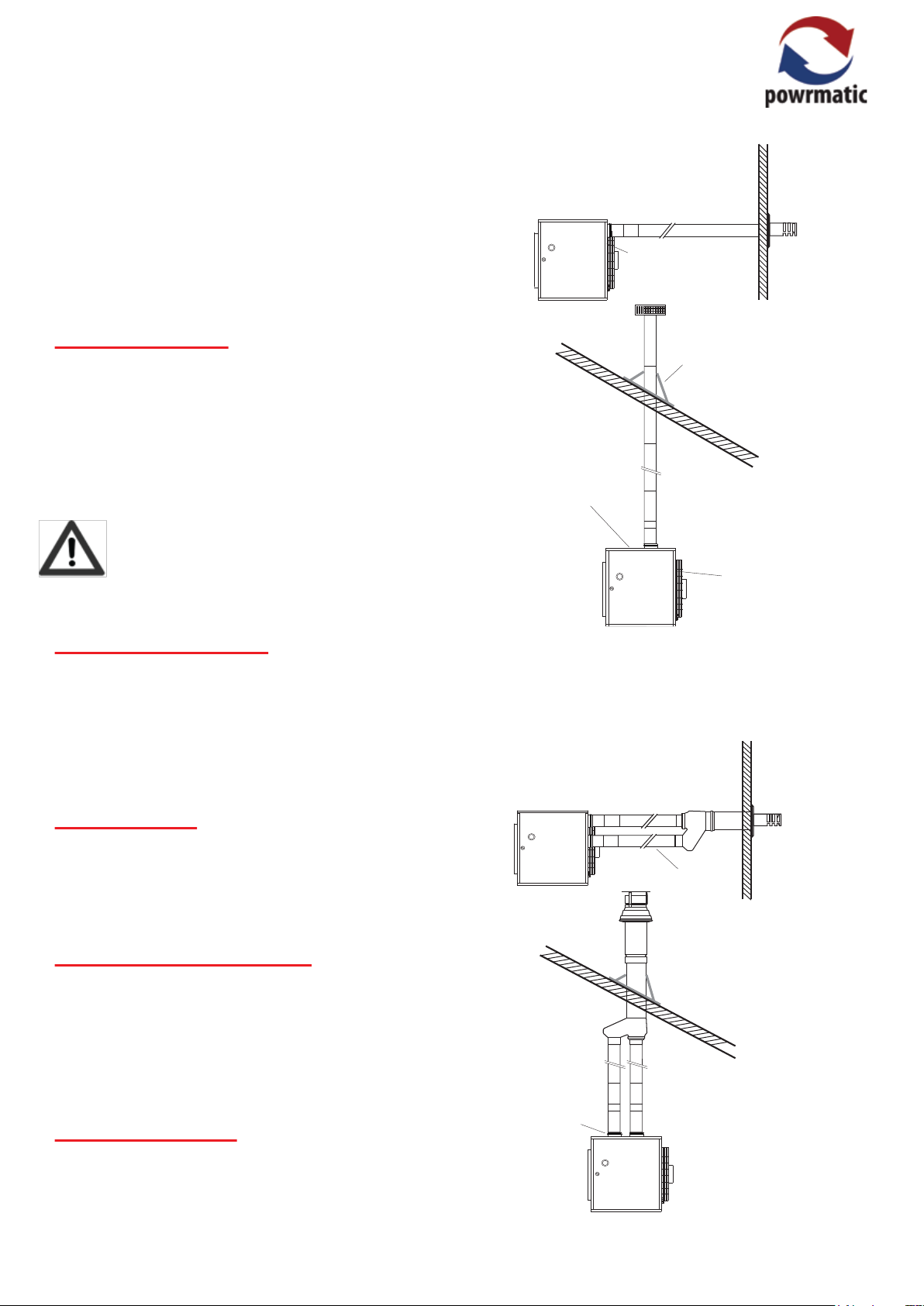
combustion air ducts are available.
Type B22 Installation,
Combustion air entry
(fitted with inlet grille and
inlet bend (not shown))
Flashing
Combustion air entry
(fitted with inlet grille)
Combustion air entry
(fitted with inlet grille and
inlet bend (not shown))
1.2.4.1 Service Pipes
The local gas undertaking should be consulted at the
installation planning stage in order to establish the availability of an adequate supply of gas. An existing service
pipe must not be used without prior consultation with the
local gas undertaking. The inlet gas pressure under
running conditions must not be less than 17.5mb.
1.2.4.2 Meters
An existing meter should be checked, preferably by the
gas undertaking, to ensure that the meter is adequate to
deal with the total rate of gas supply required by all
connected equipment.
1.2.4.3. Installation Pipes
Installation pipes should be fitted in accordance with
IGE/UP/2. Pipe work from the meter to the air heater must
be of adequate size. Do not use pipes of a smaller size
than the inlet gas connection of the heater. The complete
installation must be tested for soundness as described in
the above Code.
The flue must terminate in a freely exposed position and
be sited to prevent the products of combustion entering
any opening in a building in such concentration as to be
prejudicial to health or a nuisance.
Type C12 or C32 Installation,
Combustion
air duct
Combustion air
1.2.5 Flue System
socket
Only flue systems supplied through Powrmatic Ltd may be
used with NVx units. Several configurations of flue and
NVX Range Users, Instrucons & Service Instrucons Issue 5.5 August 2015 Page 7
1.2.6 Combustion & Ventilation Air
Supply
2) Installation in plant rooms or enclosures
There must be permanent air vents communicating directly with the outside air, at high level and at low level.
There shall be provision for a supply of air for combustion
and, in the case of heaters installed in an enclosure or
plant room, for ventilation.
1) Installation in the heated space
In buildings with a design air change rate of 0.5 /h or
greater, additional natural or mechanical ventilation is not
necessary.
In buildings not having a design air change rate of 0.5 /h
the following apply.
Natural Ventilation
Grilles having a free area of at least 2cm² per kW of rated
heat input shall be provided at low level i.e. below the
level of the heater flue connection.
Mechanical Ventilation
Must ensure that the space air change rate is at least
0.5/h, must be of the ‘input’ type and interlocked to ensure
the heaters cannot work if the input system is not working.
Plant Rooms
Low level (inlet) 4cm²/kw of total rated net heat input
High level (outlet) 2cm²/kw of total rated net heat input
Enclosures
Low level (inlet) 10cm²/kw of total rated net heat input
High level (outlet) 5cm²/kw of total rated net heat input
Mechanical Ventilation
The minimum flow rate of ventilation shall be 4.14m³/h per
kilowatt of total rated heat input.
1) Installation in the heated space
No additional provision for the supply of air is necessary.
2) Installation in a plant room or enclosure
If the means of ventilation is to a room or internal space
then high and low level vents each having a free area of
10cm² per kW (net) of maximum heat input shall be fitted.
If the means of ventilation is direct to outside air then high
and low level vents each having a free area of 5cm² per
kW (net) of maximum heat input shall be fitted.
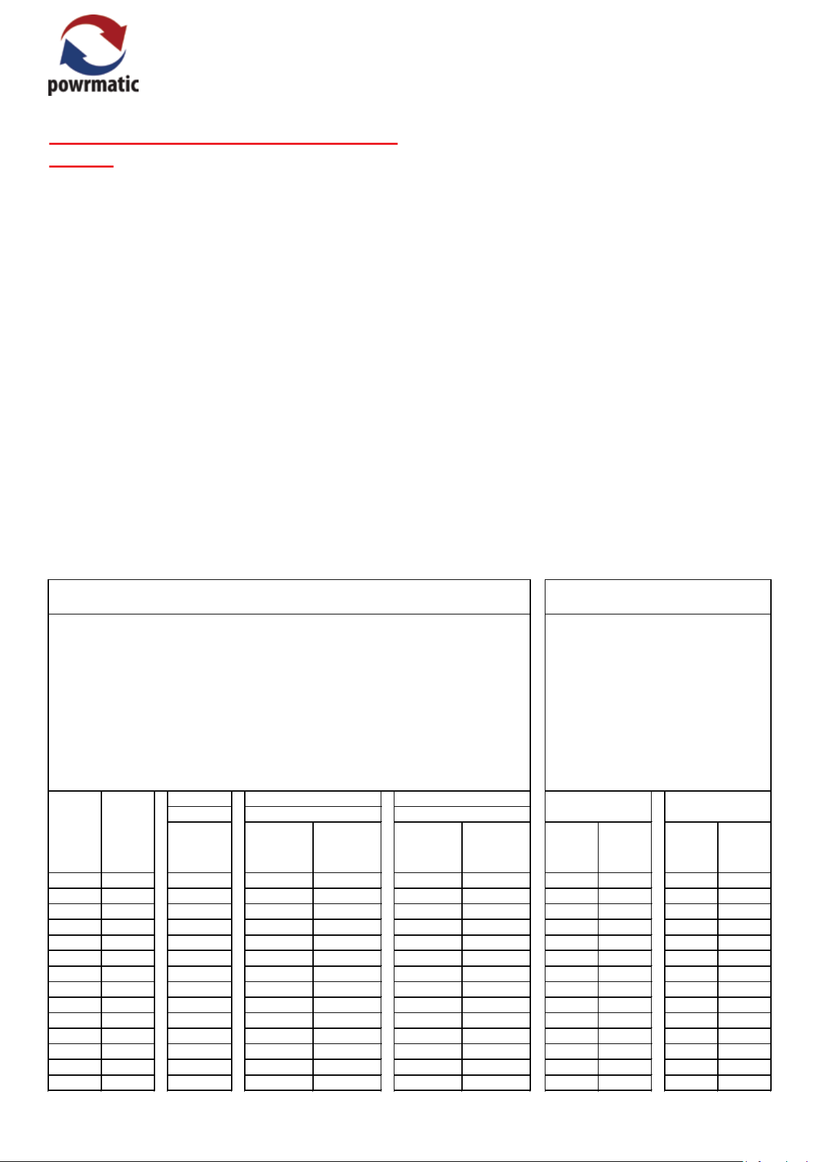
Type B22 Installaon
These refer to Secon 2.2 of the instrucons
Air vents shall be permanently open.
Figures in Column 1 are for heaters installed in the space they are heang.
Figures in column 2 are for heaters sited in a pla
Figures in column 3 are for heaters installed in an enclosure, venlaon to outside air.
In all cases figures are per heater installed.
For mul heater installaons the appropriate values for each heater must be added together.
1 3
In the space
Input kWNVx
10 10.8 21.6 43.2 21.6 108.0 54.0 108.0 108.0 54.0 54.0
15 16.0 32.0 64.0 32.0 160.0 80.0 160.0 16
20 21.9 43.8 87.6 43.8 219.0 109.5 219.0 219.0 109.5 109.5
25 27.3 54.6 109.2 54.6 273.0 136.5 273.0 273.0 136.5 136.5
30 32.6 65.2 130.4 65.2 326.0 163.0 326.0 326.0 163.0 163.0
35 39.3 78.6 157.2 78.6 393.0 196.5 393.0 393.0 196.5 196.5
40 43.5 87.0 174.0 87.0 435.0 217.5 435.0 435.0 217.5 217.5
50 54.2 108.4 216.8 108.4 542.0 271.0 542.0 542.0 271.0 271.0
60 65.6 131.2 262.4 131.2 656.0 328.0 656.0 656.0 328.0 328.0
75 81.3 162.6 325.2 162.6 813.0 406.5 813.0 813.0 40
90 & 90S 95.3 190.6 381.2 190.6 953.0 476.5 953.0 953.0 476.5 476.5
120 130.1 260.2 520.4 260.2 1301.0 650.5 1301.0 1301.0 650.5 650.5
140 148.9 297.8 595.6 297.8 1489.0 744.5 1489.0 1489.0 744.5 744.5
Low Level
Grille
Free Area
cm² cm² cm² cm² cm² cm² cm² cm² cm²
Low Level
Free Area
nt room, venlaon to outside air.
2
In a plant room In an enclosure
Grille
High Level
Grille
Free Area
Low Level
Grille
Free Area
High Level
Free Area
Grille
Type C
These refer to Secon 2.2 of the instrucons
Air vents shall be permanently open.
Figures are for heaters in plant rooms or
enclosures.
Figures in column 1 are where venlaon
is to a room or in
Figures in column 2 are where venlaon
is to outside air.
In all cases figures are per heater installed.
For mul heater installaons the
appropriate values for each heater must be
added together.
Low Level
Free Area
or C32 Installaon
12
ternal space.
1 2
High Level
Grille
Grille
Free Area
0.0 80.0 80.0
Low Level
Grille
Free Area
6.5 406.5
High Level
Grille
Free Area
Page 8 NVX Range Users, Instrucons & Service Instrucons Issue 5.5 August 2015
1.2.7 Air Distribution System
Where NVx/F units are required to cover a large floor
area, and in buildings with high roof or ceiling heights
Calecon thermal economiser units may be considered to
ensure even heat distribution and minimise stratification.
Care should be taken to avoid impeding the air throw with
racking, partitions, plant or machinery etc. Various outlet
configurations are available as optional extras to modify
the air throw pattern to suit particular site conditions.
For ducted units, the duct work must comply to current
regulations and be correctly calculated to match the
particular heaters resistance and air flow.
A full and unobstructed return air path to the air heater(s)
must be provided.
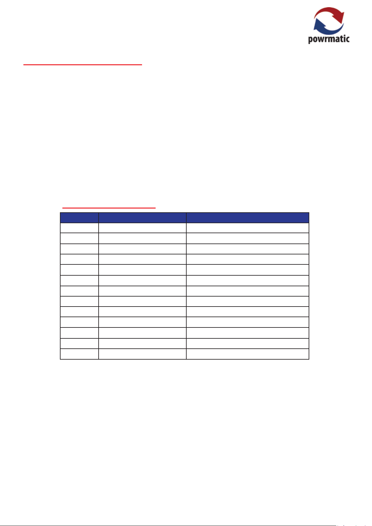
Ducting Requirements
Model Air Volume m3/h Maximum Duct Resistance
NVx10 936 140
NVx15 1405 145
NVx20 1873 177
NVx25 2341 143
NVx30 2809 250
NVx35 3600 210
NVx40 3746 236
NVx50 4682 205
NVx60 5619 250
NVx75 7024 260
NVx90 8428 200
NVx120 11237 284
NVx140 13110 285
If the air heater(s) is installed in a plant room, the return air
intake(s) and the warm air outlet(s) from the heater(s)
must be fully ducted, into and out of the plant room to
avoid interference with the operation of the heater.
The openings in the structure of the plant room/enclosure
through which the ducting passes must be fire stopped.
Care must be taken to ensure that return-air intakes are
kept clear of sources of smells and fumes, and where
there is any possibility of pollution of the air by dust, shavings etc., precautions must be taken to prevent contamination.
If necessary, suitable barrier rails should be provided to
prevent any combustible material being placed within
900mm of the outlets.
NVX Range Users, Instrucons & Service Instrucons Issue 5.5 August 2015 Page 9
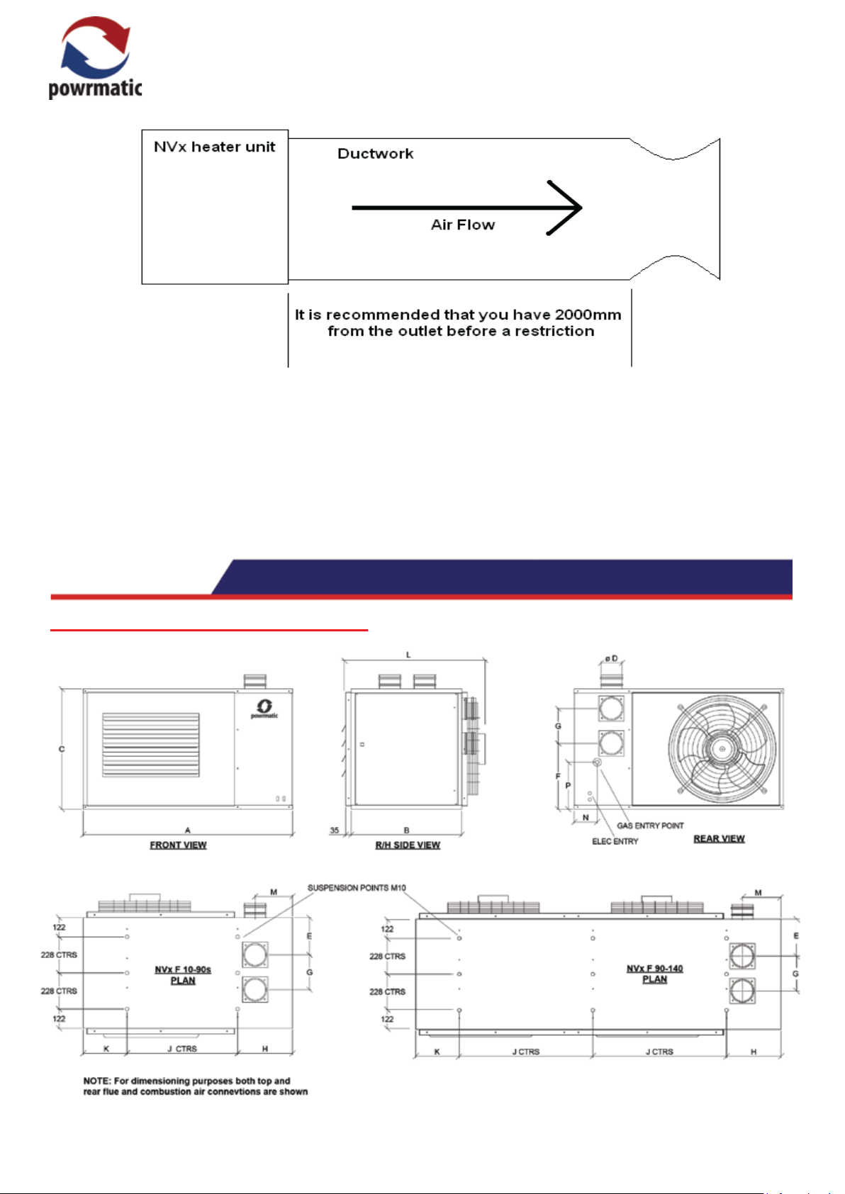
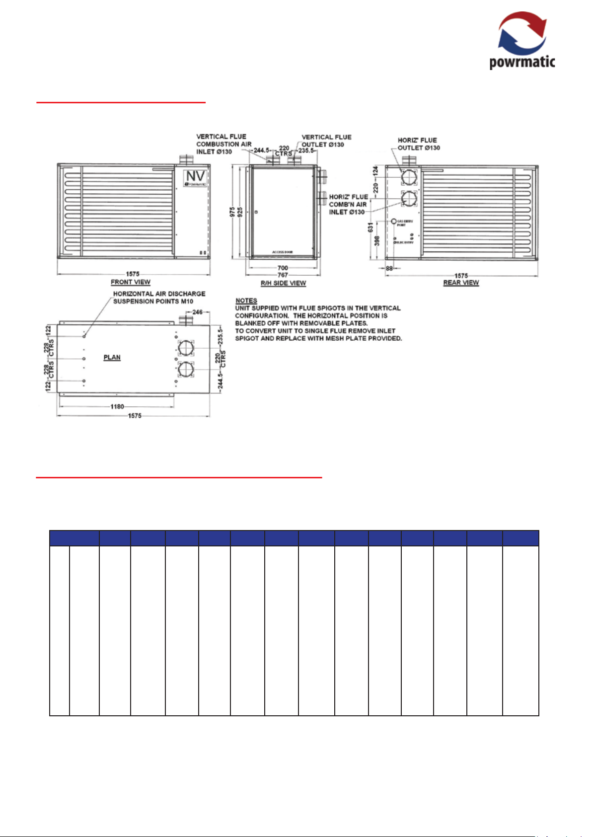
NVx F - Axial Fan Crossflow Units
1.3 Size Data
Page 10 NVX Range Users, Instrucons & Service Instrucons Issue 5.5 August 2015
NVx 90S - Single Fan Unit
NVx F / NVx90S - Axial Fan Crossflow Units
Model
A
B
C
DØ
E
F
G
H
J
K
L
M
N
P
mm
mm
mm
mm
mm
mm
mm
mm
mm
mm
mm
mm
mm
mm
10 15 20 25 30 40 50 60 75 90S 90 120
785
700
540
80
248
308
120
317
250
218
892
216
114
194
1000
700
540
80
248
308
120
317
250
232.5
892
216
114
194
1000
700
540
80
248
308
120
317
450
232.5
925
216
114
194
1000
700
540
80
248
308
120
317
450
232.5
925
216
114
194
1000
700
760
100
233.5
492
142
317
450
232.5
925
206
114
297
1000
700
760
100
233.5
492
142
317
450
232.5
905
206
114
297
1000
700
912
100
233.5
644
142
317
450
232.5
925
206
114
374
1325
700
760
130
235.5
416
220
347
700
278
939
236
145
297
1325
700
912
130
235.5
568
220
347
700
278
985
236
145
374
1575
700
975
130
235.5
631
220
347
950
278
915
246
88
398
2325
700
700
130
235.5
321
220
347
850
278
925
246
88
260
2325
700
831
130
235.5
487
220
347
850
278
939
246
88
326
140
2325
700
975
130
235.5
631
220
347
850
278
939
246
88
398
NVX Range Users, Instrucons & Service Instrucons Issue 5.5 August 2015 Page 11
 Loading...