

Powrmatic NVx15CCF, NVx20CCF, NVx25CCF, NVx30CCF, NVx40CCF User, Installation & Servicing Manual
...
NVx Suspended Gas Unit Heater
Industrial & Commercial Heating Systems
Issue 6.4 Aug 2017
User, Installation
& Servicing Manual
www.powmatic.co.uk
+44 (0) 1460 53535
info@powrmatic.co.uk
powrmatic
ertificate of Guarantee
C
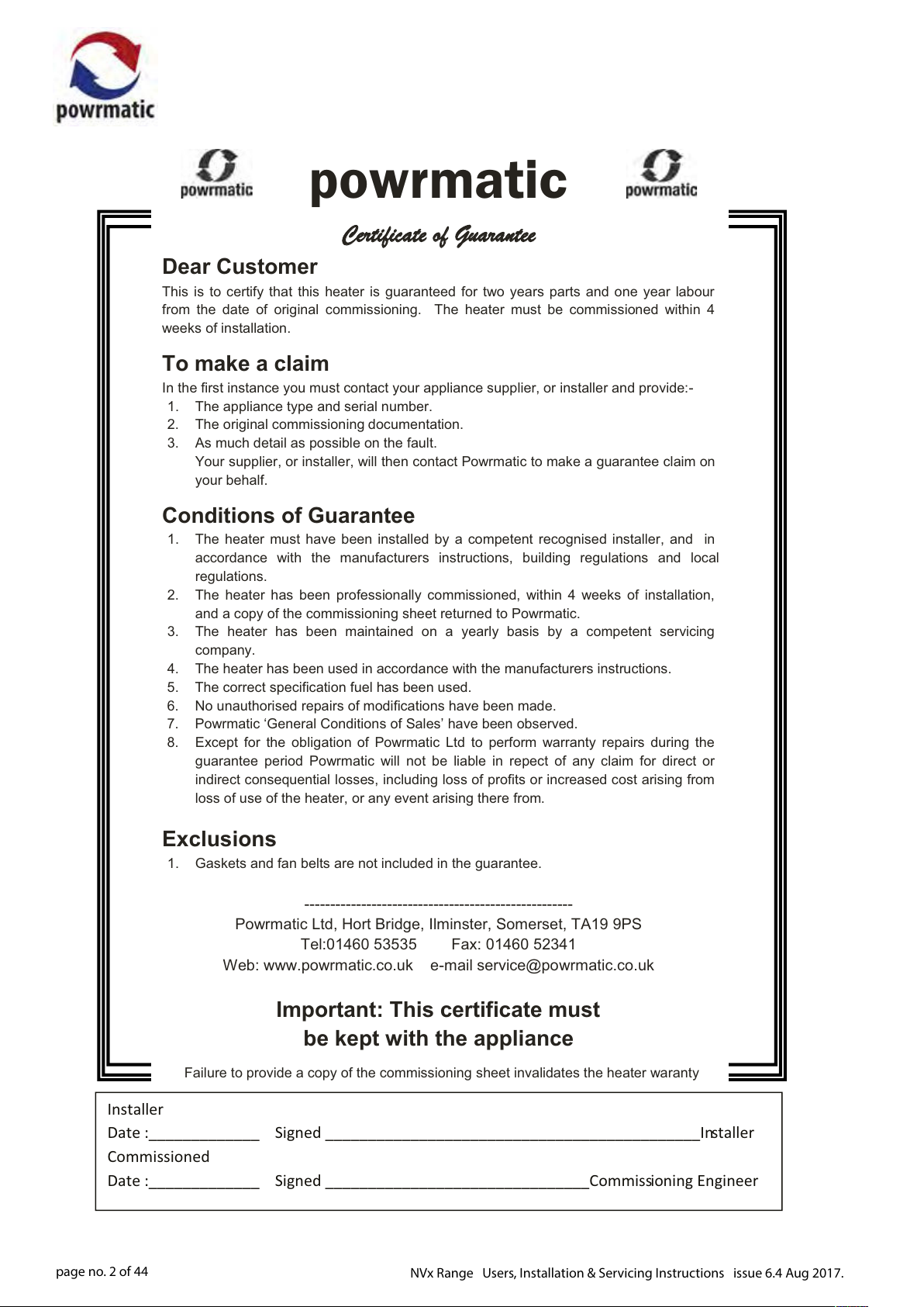
Dear Customer
This is to certify that this heater is guaranteed for two years parts and one year labour
from the date of original commissioning. The heater must be commissioned within 4
weeks of installation.
To make a claim
In the first instance you must contact your appliance supplier, or installer and provide:-
1. The appliance type and serial number.
2. The original commissioning documentation.
3. As much detail as possible on the fault.
Your supplier, or installer, will then contact Powrmatic to make a guarantee claim on
your behalf.
Conditions of Guarantee
1. The heater must have been installed by a competent recognised installer, and in
accordance with the manufacturers instructions, building regulations and local
regulations.
2. The heater has been professionally commissioned, within 4 weeks of installation,
and a copy of the commissioning sheet returned to Powrmatic.
3. The heater has been maintained on a yearly basis by a competent servicing
company.
4. The heater has been used in accordance with the manufacturers instructions.
5. The correct specification fuel has been used.
6. No unauthorised repairs of modifications have been made.
7. Powrmatic ‘General Conditions of Sales’ have been observed.
8.
Except for the obligation of Powrmatic Ltd to perform warranty repairs during the
guarantee period Powrmatic will not be liable in repect of any claim for direct or
indirect consequential losses, including loss of profits or increased cost arising from
loss of use of the heater, or any event arising there from.
Exclusions
1. Gaskets and fan belts are not included in the guarantee.
----------------------------------------------------
Powrmatic Ltd, Hort Bridge, Ilminster, Somerset, TA19 9PS
Tel:01460 53535 Fax: 01460 52341
Web: www.powrmatic.co.uk e-mail service@powrmatic.co.uk
Important: This certificate must
Installer
Date :_____________ Signed ____________________________________________Installer
Commissioned
Date :_____________ Signed _______________________________Commissioning Engineer
page no. 2 of 44
be kept with the appliance
Failure to provide a copy of the commissioning sheet invalidates the heater waranty
NVx Range Users, Installation & Servicing Instructions issue 6.4 Aug 2017.
Dear Customer - thank you for choosing Powrmatic.
We appreciate you buying one of our high quality products and know that you have made the best
choice. By choosing Powrmatic, you are investing in UK manufacturing & its workforce. We pride
ourselves by manufacturing products that provide clean, comfortable and safe working environments
worldwide together with the personal & professional service and back-up you deserve. If you have
any questions or concerns regarding this product, please contact our Technical Support Team by
calling 01460 53535.
Users, Installation and Servicing Instructions
CONTENTS
Title Section Contents Page
User Instructions 4
Pre Installation
1.1 Introduction 5
Duties 6
Dimensions 7
Accessories 12
1.2 Technical data 14
1.3 General Requirements 16
Installation
2.1 Fitting the unit 20
2.2 Flue/Combustion Air Duct System 22
2.3 General Identication of Electrical Items 24
2.4 Electrical Cable Installation 25
2.5 Wiring Diagrams 27
2.6 Commissioning and Testing 32
2.7 Servicing 36
Additional Documents
3.1 Fault Finding Flow Chart 40
3.2 Short List of Parts 42
NVx Range Users, Installation & Servicing Instructions issue 6.4 Aug 2017.
page no. 3 of 44
User Instructions
If the heater has not been left operational
proceed as follows.
A) Checks before lighting the Air Heater
The following preliminary checks should be made before
lighting the heater(s)
a) Ensure that the ELECTRICAL supply to the heater is
switched OFF.
b) Check that all warm air delivery outlets are open.
c) Check that the thermostat is set at MAX.
d) Check that the clock control is set to an ON period.
e) Check that any other controls are calling for heat.
B) Lighting the Air Heater
1. Switch on the electrical supply at the isolator
2. If the Limit indicator light comes on press the limit
interlock reset switch inside the heater.
3. The startup sequence will commence. After a short
delay the burners will light and the green ‘ON’ indicator on
the front of the heater will be illuminated.
D) Description of Operation
Important: The heater must NOT be
controlled by switching ON and OFF the
main electrical supply to it.
1) Standard Units
The ignition sequence commences each time the external
controls e.g. Time clock, room thermostat etc. call for
heat. The internal exhaust fan will run and, when sucient
combustion airow is proved by the air pressure switch,
the ignition spark will be generated, the main gas valve
opens and the burners light. The green ‘ON’ indicator
will be illuminated. The heater fan will automatically start
approximately 2 minutes after the burners light. When the
external controls are satised the burners will be turned
o and approximately 2 - 3 minutes later the heater fan will
be automatically stopped. If the burners fail to light the
control box will make another four attempts at ignition.
2) High / Lo & Modulating Units
When the burners are alight, the heat output will be
controlled either to high re or low re or, in the case of
modulating units, to any point between high and low re;
depending on the requirements of the space being heated
and the external controls tted.
4. If the burners fail to light the control box will
automatically restart the ignition sequence. If after 5
attempts at ignition the burners have still failed to light
the control box will go to lockout and the Amber lockout
light on the front of the heater (or on the low level remote
reset, MC200 or Powrtrol RR if tted) will be illuminated. To
restart the ignition sequence depress the reset button on
the low level reset for about 1-2 seconds.
WARNING: If it is not possible to light the
heater after several attempts, contact the
installer or local service company.
C) To Shut Down the Air Heater
1) For Short Periods:
Turn the room thermostat to the OFF, or set to it’s lowest
setting.
2) For Long Periods:
Complete step 1 above. Wait for 5 minutes and then turn
OFF the electrical supply at the isolator.
3) Summer / Winter Modes
Certain types of external controls will provide for two
modes of operation i.e.
Summer: The heater fan alone will run at the dictate of the
external controls to provide air movement.
Winter: The heater will operate normally.
4) Overheat Thermostat
This operates if high temperatures within the heater are
detected, the burners are turned o and a Red indicator
switch light on the front panel is illuminated. NVx15 - 75
units have the thermostat located inside the controls
section. NVx90SF - 140SF units have an additional
thermostat on the side of the unit at the opposite end to
the controls (either thermostat can go to limit and shut o
the burners). The fault condition must be identied and
rectied and the thermostat manually reset via the red
high limit reset switch. When the unit has cooled, push the
Red indicator switch inside the front panel to reset the limit
thermostat interlock relay, the red indicator light will go
out and the unit is operational again.
Note: The limit thermostat(s) can only be reset
once the unit has cooled down.
Unless the cause of the fault condition is
readily obvious, for example a power cut whilst
page no. 4 of 44
NVx Range Users, Installation & Servicing Instructions issue 6.4 Aug 2017.
the heater was operating, a service engineer should be
contacted.
and belts. It would be hazardous to tamper with or attempt
to service unless you are a competent person in the eld of
Gas and Electrical work.
E) Maintenance
To maintain ecient, reliable and safe operation of the
heater it must serviced by a qualied person at least
annually and preferably at the end of the heating season.
F) IMPORTANT
Free access must be maintained to and around the heater
for servicing purposes and the air supply to the heater
must not be restricted in any way. Combustible materials
must not be stored adjacent to the heater.
If at any time a gas leak is suspected, turn OFF the gas
supply at the meter and contact the local gas undertaking
immediately.
All Powrmatic heaters use gas and electricity to power
them, they may also contain moving parts such as pulleys
1.1 Introduction
The NVx range are highly ecient, gas red, fanned
circulation air heaters that cover heat outputs of 15kW to
140kW, have a closed combustion circuit and are supplied
complete with a ue system. They are certied for use
on Natural Gas, Group H - G20, and Propane - G31 only.
Appliance Categories are Cat II2H3P (GB, IE).
The heaters are designed to be suspended from suitable
roof points or alternatively to be mounted on purpose
designed brackets and are intended primarily for heating
commercial or industrial premises. All variants, with the
exception of NVx/EA units, are for internal use only.
NVx heaters feature a closed combustion circuit and have
an internal exhaust fan, mounted downstream of the
heat exchanger, to evacuate the products of combustion
and draw in air for combustion. The air heater must be
connected to a ue system that is approved by Powrmatic
Ltd.
They may be used where the atmosphere inside the
premises could be contaminated e.g. Dust, oil mist etc. but
the heaters are not airtight and therefore may not be used
in areas classied as hazardous as dened in BS 5345: Part 2
or areas subjected to signicant negative pressures due to
extract systems.
NVx/F heaters have an axial fan assembly tted at the
rear to circulate the air being heated through the formed
tube heat exchanger. NVx/CCF units are supplied with
a centrifugal fan and NVx/D units for use with ducted
systems where the air moving fan is by others or a
If you have any safety questions reference the servicing
and installation of any of our heaters please do not hesitate
to contact our head oce for expert advice. Your safety is
paramount to us.
Gas Safety (Installation & Use) (Amendment)
Regulations
It is law that all gas appliances are
installed, adjusted and, if necessary,
converted by qualied persons* in
accordance with the current issue of the
above regulations. Failure to install appliances
correctly can lead to prosecution. It is in your own
interests and that of safety to ensure that the law is
complied with.
* An approved class of person listed on the gas safe
register.
centrifugal fan section is used adjacent to or remote from
the heater. NVx/DH units are for use in air handling units
and NVx/EA units are for siting externally.
Heaters are tted as standard with inshot burners, a fully
automatic control for ignition, ame sensing, gas supply
control and safety functions, an internal exhaust fan, main
air fan (/F and /C models), and fan/limit thermostat.
Options include High/Low or Modulating burner controls,
inlet duct connection, outlet duct connection, 30°, 45°
head, 90° outlet bend, vertical/horizontal outlet louvre
assembly and a full range of modular duct components.
IMPORTANT
Service and Maintenance Engineers shall
ensure that replacement items are tted,
adjusted and set in accordance with the
data and detail set out in these instructions. If in doubt
consult Powrmatic Technical Department.
Gas Safety (Installation & Use) Regulations 1998
It is law that all gas appliances are
installed, adjusted and, if necessary,
converted by qualied persons* in
accordance with the current issue of the
above regulations. Failure to install appliances
correctly can lead to prosecution. It is in your own
interests and that of safety to ensure that the law is
complied with.
* An approved class of person listed on the gas safe
register.
NVx Range Users, Installation & Servicing Instructions issue 6.4 Aug 2017.
page no. 5 of 44
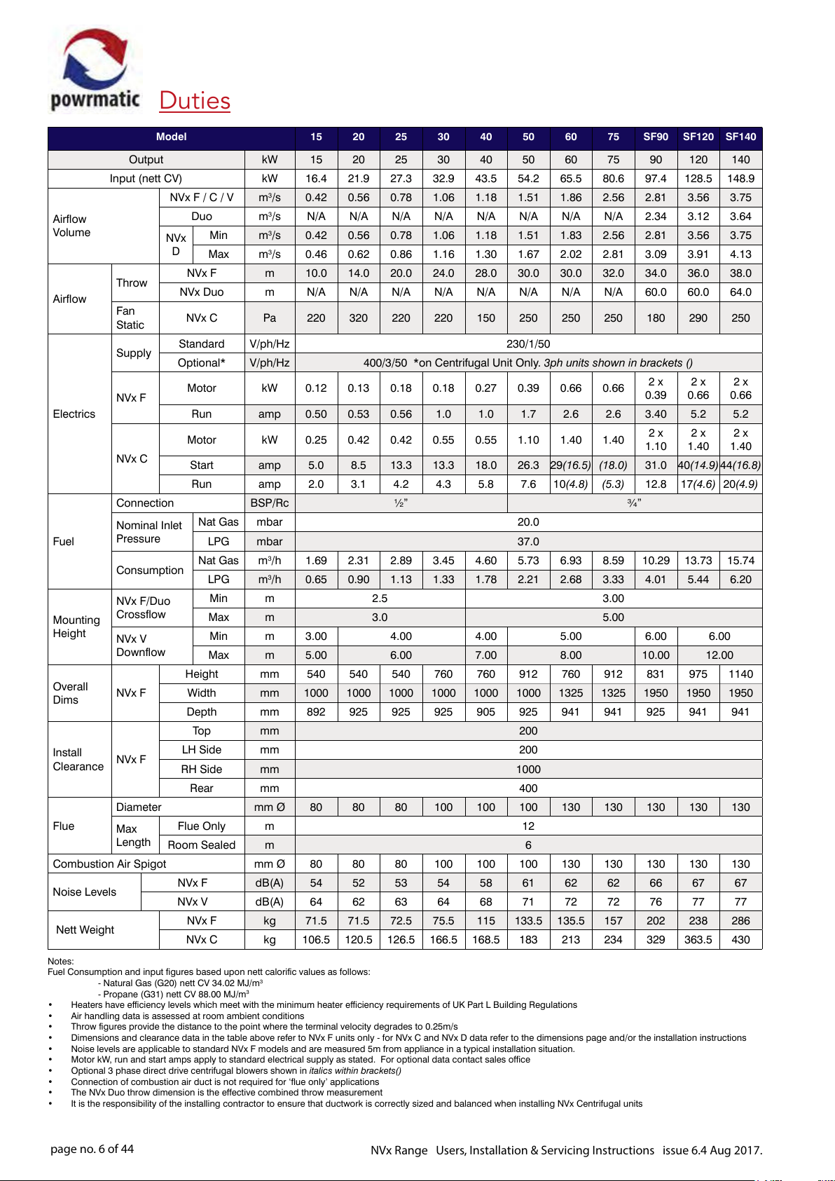
Duties
Model 15 20 25 30 40 50 60 75 SF90 SF120 SF140
Output kW 15 20 25 30 40 50 60 75 90 120 140
Input (nett CV) kW 16.4 21.9 27.3 32.9 43.5 54.2 65.5 80.6 97.4 128.5 148.9
NVx F / C / V m
Airflow
Volume
Throw
Airflow
Fan
Static
Supply
NVx F
Electrics
Duo m
D
Min m
Max m
NVx
NVx F m 10.0 14.0 20.0 24.0 28.0 30.0 30.0 32.0 34.0 36.0 38.0
NVx Duo m N/A N/A N/A N/A N/A N/A N/A N/A 60.0 60.0 64.0
NVx C Pa 220 320 220 220 150 250 250 250 180 290 250
Standard V/ph/Hz 230/1/50
Optional* V/ph/Hz 400/3/50 *on Centrifugal Unit Only. 3ph units shown in brackets ()
Motor kW 0.12 0.13 0.18 0.18 0.27 0.39 0.66 0.66
Run amp 0.50 0.53 0.56 1.0 1.0 1.7 2.6 2.6 3.40 5.2 5.2
Motor kW 0.25 0.42 0.42 0.55 0.55 1.10 1.40 1.40
NVx C
Start amp 5.0 8.5 13.3 13.3 18.0 26.3 29(16.5) (18.0) 31.0 40(14.9)44(16.8)
Run amp 2.0 3.1 4.2 4.3 5.8 7.6 10(4.8) (5.3) 12.8 17(4.6) 20(4.9)
Connection BSP/Rc ½” ¾”
Nat Gas mbar 20.0
LPG mbar 37.0
Nat Gas m
LPG m
Min m 2.5 3.00
Max m 3.0 5.00
Min m 3.00 4.00 4.00 5.00 6.00 6.00
Max m 5.00 6.00 7.00 8.00 10.00 12.00
Fuel
Mounting
Height
Nominal Inlet
Pressure
Consumption
NVx F/Duo
Crossflow
NVx V
Downflow
Height mm 540 540 540 760 760 912 760 912 831 975 1140
Overall
Dims
NVx F
Width mm 1000 1000 1000 1000 1000 1000 1325 1325 1950 1950 1950
Depth mm 892 925 925 925 905 925 941 941 925 941 941
To p mm 200
Install
Clearance
NVx F
LH Side mm 200
RH Side mm 1000
Rear mm 400
Diameter mm Ø 80 80 80 100 100 100 130 130 130 130 130
Flue
Max
Length
Flue Only m 12
Room Sealed m 6
Combustion Air Spigot mm Ø 80 80 80 100 100 100 130 130 130 130 130
Noise Levels
eight
Nett W
Notes:
Fuel Consumption and input figures based upon nett calorific values as follows:
- Natural Gas (G20) nett CV 34.02 MJ/m
- Propane (G31) nett CV 88.00 MJ/m
• Heaters have efficiency levels which meet with the minimum heater efficiency requirements of UK Part L Building Regulations
• Air handling data is assessed at room ambient conditions
• Throw figures provide the distance to the point where the terminal velocity degrades to 0.25m/s
Dimensions and clearance data in the table above refer to NVx F units only - for NVx C and NVx D data refer to the dimensions p
•
• Noise levels are applicable to standard NVx F models and are measured 5m from appliance in a typical installation situation.
• Motor kW, run and start amps apply to standard electrical supply as stated. For optional data contact sales office
• Optional 3 phase direct drive centrifugal blowers shown in italics within brackets()
• Connection of combustion air duct is not required for ‘flue only’ applications
• The NVx Duo throw dimension is the effective combined throw measurement
• It is the responsibility of the installing contractor to ensure that ductwork is correctly sized and balanced when installing NVx Centrifugal units
NVx F dB(A) 54 52 53 54 58 61 62 62 66 67 67
NVx V dB(A) 64 62 63 64 68 71 72 72 76 77 77
NVx F kg 71.5 71.5 72.5 75.5 115 133.5 135.5 157 202 238 286
NVx C kg 106.5 120.5 126.5 166.5 168.5 183 213 234 329 363.5 430
3
/s 0.42 0.56 0.78 1.06 1.18 1.51 1.86 2.56 2.81 3.56 3.75
3
/s N/A N/A N/A N/A N/A N/A N/A N/A 2.34 3.12 3.64
3
/s 0.42 0.56 0.78 1.06 1.18 1.51 1.83 2.56 2.81 3.56 3.75
3
/s 0.46 0.62 0.86 1.16 1.30 1.67 2.02 2.81 3.09 3.91 4.13
2 x
0.39
2 x
1.10
3
/h 1.69 2.31 2.89 3.45 4.60 5.73 6.93 8.59 10.29 13.73 15.74
3
/h 0.65 0.90 1.13 1.33 1.78 2.21 2.68 3.33 4.01 5.44 6.20
3
3
age and/or the installation instructions
2 x
0.66
2 x
1.40
2 x
0.66
2 x
1.40
page no. 6 of 44
NVx Range Users, Installation & Servicing Instructions issue 6.4 Aug 2017.
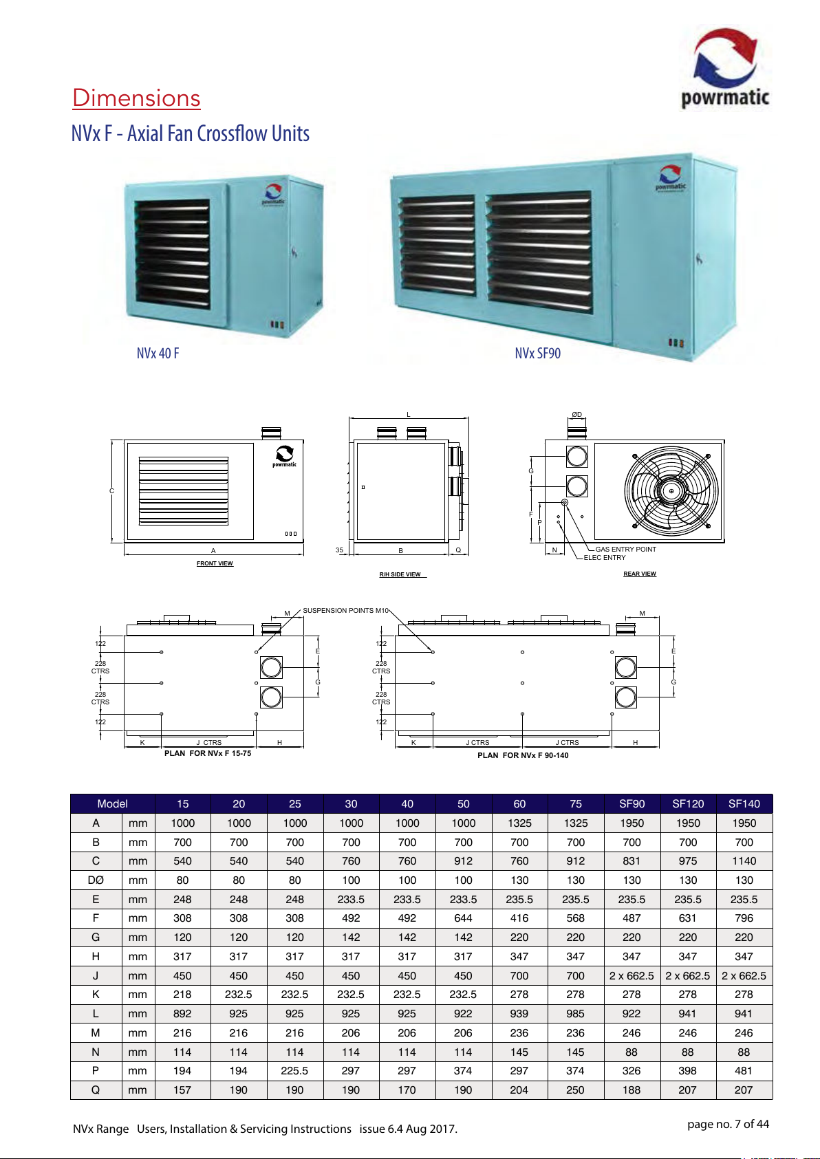
Dimensions
NVx F - Axial Fan Crossow Units
122
228
CTRS
228
CTRS
122
C
NVx 40 F
K
PLAN FOR NVx F 15-75
A
FRONT VIEW
J CTRS
SUSPENSION POINTS M10
M
E
G
H
NVx SF90
L
G
F
35
R/H SIDE VIEW
122
228
CTRS
228
CTRS
122
B
K
Q
J CTRS J CTRS
PLAN FOR NVx F 90-140
ØD
P
N
GAS ENTRY POINT
ELEC ENTRY
REAR VIEW
M
E
G
H
Model 15 20 25 30 40 50 60 75 SF90 SF120 SF140
A mm 1000 1000 1000 1000 1000 1000 1325 1325 1950 1950 1950
B mm 700 700 700 700 700 700 700 700 700 700 700
C mm 540 540 540 760 760 912 760 912 831 975 1140
DØ mm 80 80 80 100 100 100 130 130 130 130 130
E mm 248 248 248 233.5 233.5 233.5 235.5 235.5 235.5 235.5 235.5
F mm 308 308 308 492 492 644 416 568 487 631 796
G mm 120 120 120 142 142 142 220 220 220 220 220
H mm 317 317 317 317 317 317 347 347 347 347 347
J mm 450 450 450 450 450 450 700 700 2 x 662.5 2 x 662.5 2 x 662.5
K mm 218 232.5 232.5 232.5 232.5 232.5 278 278 278 278 278
L mm 892 925 925 925 925 922 939 985 922 941 941
M mm 216 216 216 206 206 206 236 236 246 246 246
N mm 114 114 114 114 114 114 145 145 88 88 88
P mm 194 194 225.5 297 297 374 297 374 326 398 481
Q mm 157 190 190 190 170 190 204 250 188 207 207
NVx Range Users, Installation & Servicing Instructions issue 6.4 Aug 2017.
page no. 7 of 44
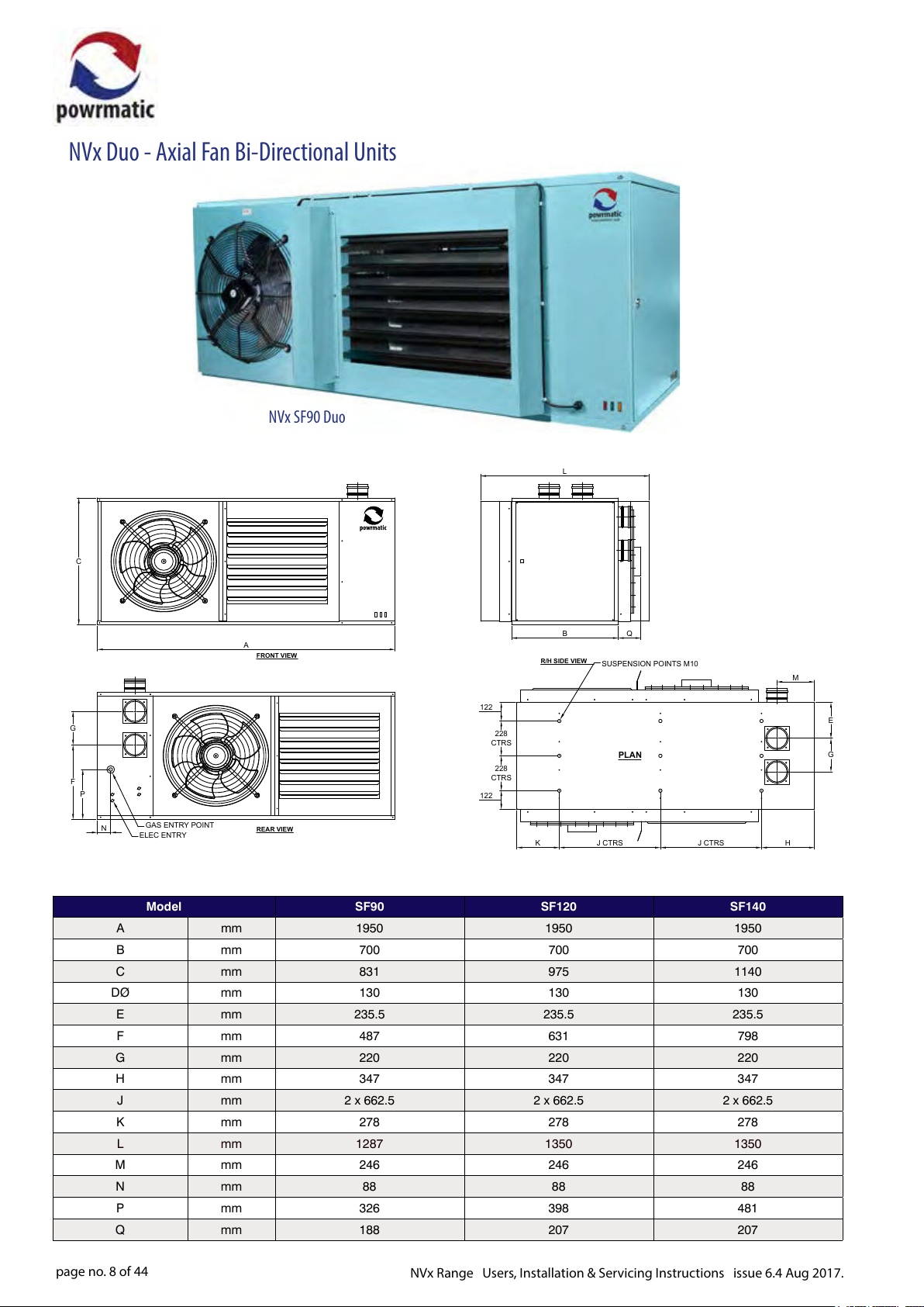
NVx Duo - Axial Fan Bi-Directional Units
NVx SF90 Duo
C
L
A
FRONT VIEW
122
G
F
P
GAS ENTRY POINT
N
ELEC ENTRY
REAR VIEW
122
228
CTRS
228
CTRS
B
R/H SIDE VIEW
K
Q
SUSPENSION POINTS M10
PLAN
J CTRS J CTRS
Model SF90 SF120 SF140
A mm 1950 1950 1950
B mm 700 700 700
C mm 831 975 1140
DØ mm 130 130 130
E mm 235.5 235.5 235.5
F mm 487 631 798
G mm 220 220 220
H mm 347 347 347
J mm 2 x 662.5 2 x 662.5 2 x 662.5
K mm 278 278 278
L mm 1287 1350 1350
M mm 246 246 246
N mm 88 88 88
P mm 326 398 481
Q mm 188 207 207
M
E
G
H
page no. 8 of 44
NVx Range Users, Installation & Servicing Instructions issue 6.4 Aug 2017.
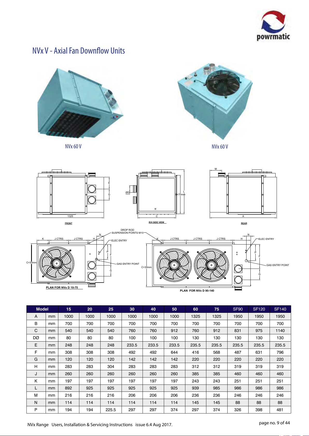
NVx V - Axial Fan Downow Units
C+30mm
NVx 60 V
1325
FRONT
J CTRS J CTRS
K H
PLAN FOR NVx D 10-75
E
G
SUSPENSION POINTS M10
N
ELEC ENTRY
P
F
G
ØD
DROP ROD
GAS ENTRY POINT
L
B+70mm
C
R/H SIDE VIEW
J CTRS J CTRS J CTRS
K H
C+30mm
PLAN FOR NVx D 90-140
NVx 60 V
M
A
REAR
N
ELEC ENTRY
P
F
G
GAS ENTRY POINT
Model 15 20 25 30 40 50 60 75 SF90 SF120 SF140
A mm 1000 1000 1000 1000 1000 1000 1325 1325 1950 1950 1950
B mm 700 700 700 700 700 700 700 700 700 700 700
C mm 540 540 540 760 760 912 760 912 831 975 1140
DØ mm 80 80 80 100 100 100 130 130 130 130 130
E mm 248 248 248 233.5 233.5 233.5 235.5 235.5 235.5 235.5 235.5
F mm 308 308 308 492 492 644 416 568 487 631 796
G mm 120 120 120 142 142 142 220 220 220 220 220
H mm 283 283 304 283 283 283 312 312 319 319 319
J mm 260 260 260 260 260 260 385 385 460 460 460
K mm 197 197 197 197 197 197 243 243 251 251 251
L mm 892 925 925 925 925 925 939 985 986 986 986
M mm 216 216 216 206 206 206 236 236 246 246 246
N mm 114 114 114 114 114 114 145 145 88 88 88
P mm 194 194 225.5 297 297 374 297 374 326 398 481
NVx Range Users, Installation & Servicing Instructions issue 6.4 Aug 2017.
page no. 9 of 44
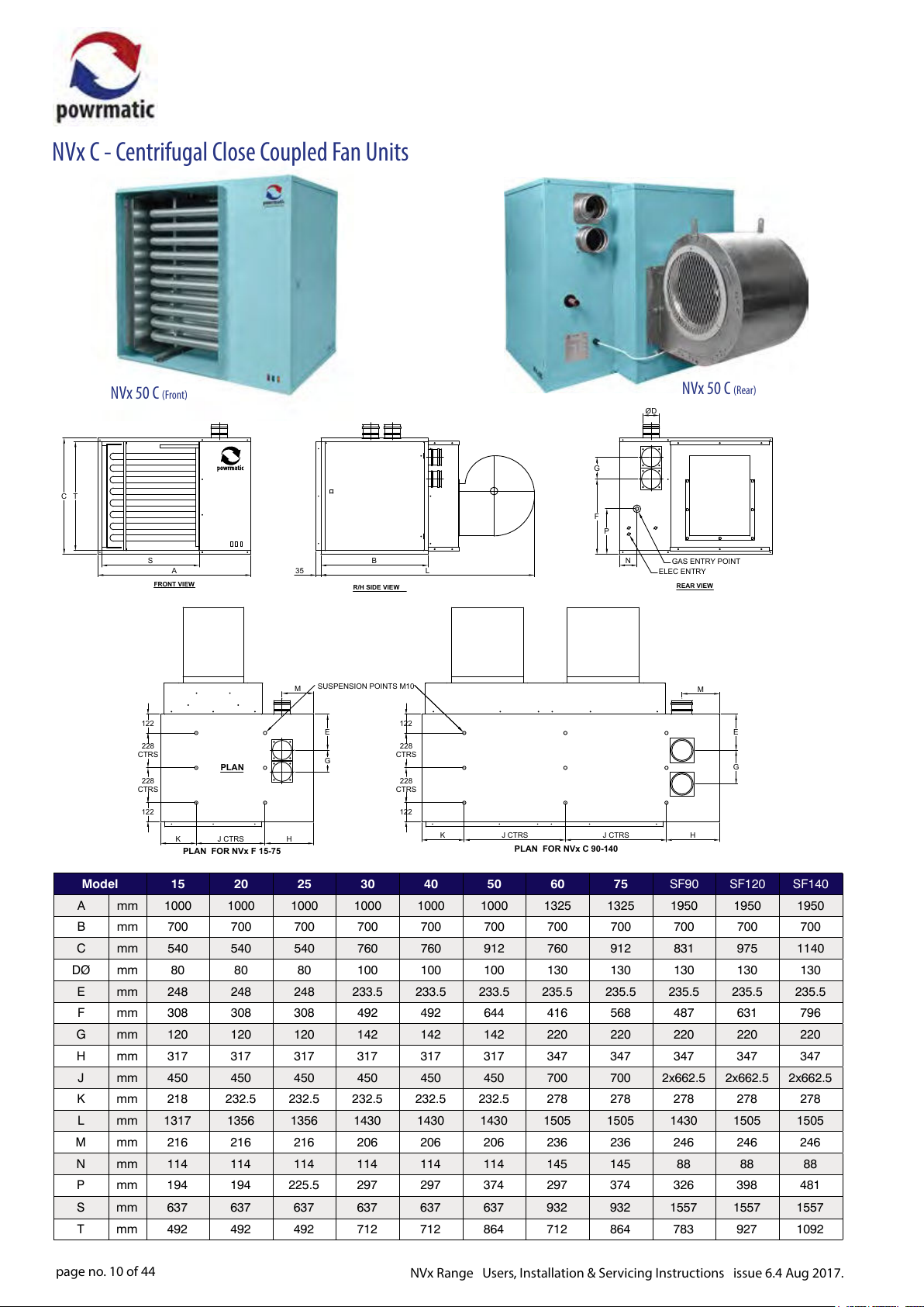
NVx C - Centrifugal Close Coupled Fan Units
TC
NVx 50 C (Front)
S
A
FRONT VIEW
122
228
CTRS
228
CTRS
122
PLAN
J CTRS
K
PLAN FOR NVx F 15-75
35
SUSPENSION POINTS M10
M
E
G
H
B
R/H SIDE VIEW
122
228
CTRS
228
CTRS
122
NVx 50 C (Rear)
ØD
G
F
P
N
L
K
J CTRS J CTRS
PLAN FOR NVx C 90-140
GAS ENTRY POINT
ELEC ENTRY
REAR VIEW
M
H
E
G
Model 15 20 25 30 40 50 60 75 SF90 SF120 SF140
A mm 1000 1000 1000 1000 1000 1000 1325 1325 1950 1950 1950
B mm 700 700 700 700 700 700 700 700 700 700 700
C mm 540 540 540 760 760 912 760 912 831 975 1140
DØ mm 80 80 80 100 100 100 130 130 130 130 130
E mm 248 248 248 233.5 233.5 233.5 235.5 235.5 235.5 235.5 235.5
F mm 308 308 308 492 492 644 416 568 487 631 796
G mm 120 120 120 142 142 142 220 220 220 220 220
H mm 317 317 317 317 317 317 347 347 347 347 347
J mm 450 450 450 450 450 450 700 700 2x662.5 2x662.5 2x662.5
K mm 218 232.5 232.5 232.5 232.5 232.5 278 278 278 278 278
L mm 1317 1356 1356 1430 1430 1430 1505 1505 1430 1505 1505
M mm 216 216 216 206 206 206 236 236 246 246 246
N mm 114 114 114 114 114 114 145 145 88 88 88
P mm 194 194 225.5 297 297 374 297 374 326 398 481
S mm 637 637 637 637 637 637 932 932 1557 1557 1557
T mm 492 492 492 712 712 864 712 864 783 927 1092
page no. 10 of 44
NVx Range Users, Installation & Servicing Instructions issue 6.4 Aug 2017.
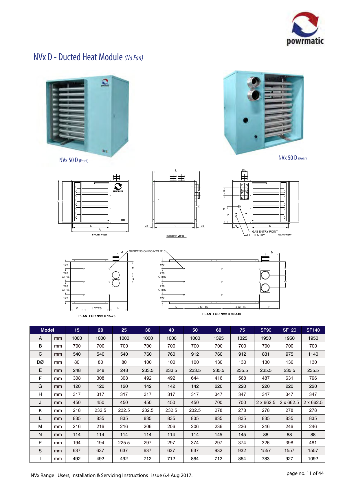
NVx D - Ducted Heat Module (No Fan)
NVx 50 D (Front)
TC
122
228
CTRS
228
CTRS
122
K
PLAN FOR NVx D 15-75
S
A
FRONT VIEW
J CTRS
SUSPENSION POINTS M10
M
E
G
H
NVx 50 D (Rear)
L
G
F
35
122
228
CTRS
228
CTRS
122
B
R/H SIDE VIEW
K
35
J CTRS J CTRS
PLAN FOR NVx D 90-140
ØD
T
P
N
ELEC ENTRY
S
GAS ENTRY POINT
M
H
REAR VIEW
E
G
Model 15 20 25 30 40 50 60 75 SF90 SF120 SF140
A mm 1000 1000 1000 1000 1000 1000 1325 1325 1950 1950 1950
B mm
700 700 700 700 700 700 700 700 700 700 700
C mm 540 540 540 760 760 912 760 912 831 975 1140
DØ mm
80 80 80 100 100 100 130 130 130 130 130
E mm 248 248 248 233.5 233.5 233.5 235.5 235.5 235.5 235.5 235.5
F mm
308 308 308 492 492 644 416 568 487 631 796
G mm 120 120 120 142 142 142 220 220 220 220 220
H mm
J mm
K mm
L mm
M mm
317 317 317 317 317 317 347 347 347 347 347
450 450 450 450 450 450 700 700 2 x 662.5 2 x 662.5 2 x 662.5
218 232.5 232.5 232.5 232.5 232.5 278 278 278 278 278
835 835 835 835 835 835 835 835 835 835 835
216 216 216 206 206 206 236 236 246 246 246
N mm 114 114 114 114 114 114 145 145 88 88 88
P mm
S mm
194 194 225.5 297 297 374 297 374 326 398 481
637 637 637 637 637 637 932 932 1557 1557 1557
T mm 492 492 492 712 712 864 712 864 783 927 1092
NVx Range Users, Installation & Servicing Instructions issue 6.4 Aug 2017.
page no. 11 of 44
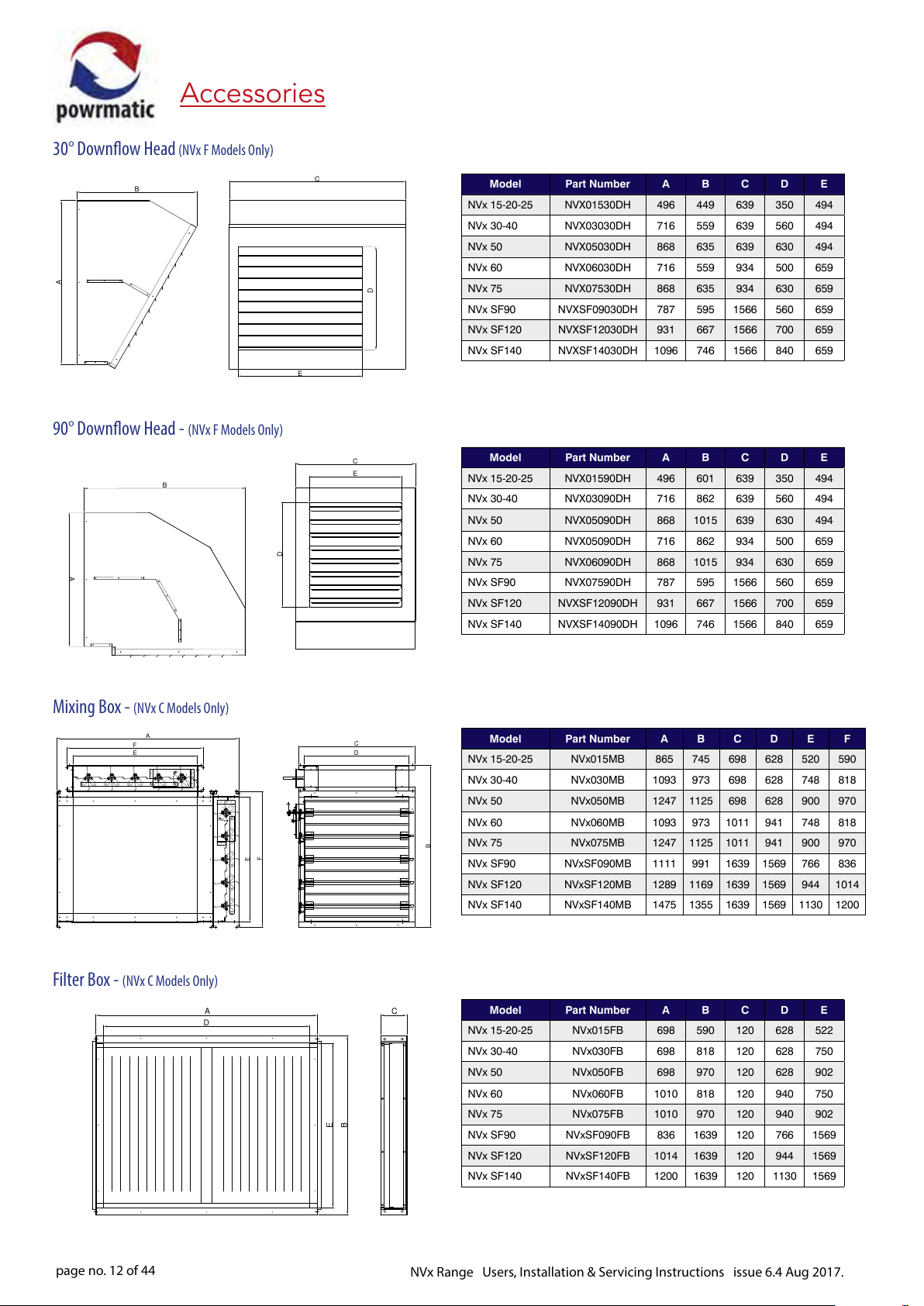
Accessories
C
A
E
30° Downow Head (NVx F Models Only)
B
90° Downow Head - (NVx F Models Only)
B
A
Model Part Number A B C D E
NVx 15-20-25 NVX01530DH 496 449 639 350 494
NVx 30-40 NVX03030DH 716 559 639 560 494
NVx 50 NVX05030DH 868 635 639 630 494
NVx 60 NVX06030DH 716 559 934 500 659
D
NVx 75 NVX07530DH 868 635 934 630 659
NVx SF90 NVXSF09030DH 787 595 1566 560 659
NVx SF120 NVXSF12030DH 931 667 1566 700 659
NVx SF140 NVXSF14030DH 1096 746 1566 840 659
C
E
Model Part Number A B C D E
NVx 15-20-25 NVX01590DH 496 601 639 350 494
NVx 30-40 NVX03090DH 716 862 639 560 494
NVx 50 NVX05090DH 868 1015 639 630 494
D
NVx 60 NVX05090DH 716 862 934 500 659
NVx 75 NVX06090DH 868 1015 934 630 659
NVx SF90 NVX07590DH 787 595 1566 560 659
NVx SF120 NVXSF12090DH 931 667 1566 700 659
NVx SF140 NVXSF14090DH 1096 746 1566 840 659
Mixing Box - (NVx C Models Only)
A
F
E
Filter Box - (NVx C Models Only)
A C
D
C
D
Model Part Number A B C D E F
NVx 15-20-25 NVx015MB 865 745 698 628 520 590
NVx 30-40 NVx030MB 1093 973 698 628 748 818
NVx 50 NVx050MB 1247 1125 698 628 900 970
NVx 60 NVx060MB 1093 973 1011 941 748 818
NVx 75 NVx075MB 1247 1125 1011 941 900 970
F
E
B
NVx SF90 NVxSF090MB 1111 991 1639 1569 766 836
NVx SF120 NVxSF120MB 1289 1169 1639 1569 944 1014
NVx SF140 NVxSF140MB 1475 1355 1639 1569 1130 1200
Model Part Number A B C D E
NVx 15-20-25 NVx015FB 698 590 120 628 522
NVx 30-40 NVx030FB 698 818 120 628 750
NVx 50 NVx050FB 698 970 120 628 902
B
E
NVx 60 NVx060FB 1010 818 120 940 750
NVx 75 NVx075FB 1010 970 120 940 902
NVx SF90 NVxSF090FB 836 1639 120 766 1569
NVx SF120 NVxSF120FB 1014 1639 120 944 1569
NVx SF140 NVxSF140FB 1200 1639 120 1130 1569
page no. 12 of 44
NVx Range Users, Installation & Servicing Instructions issue 6.4 Aug 2017.
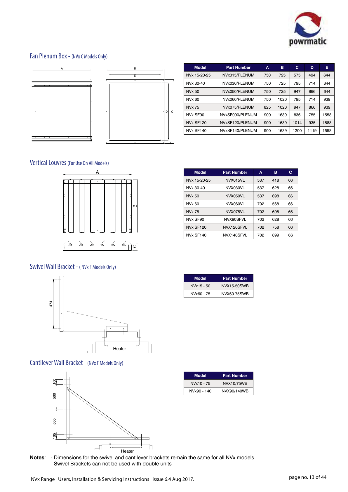
Fan Plenum Box - (NVx C Models Only)
A
Vertical Louvres (For Use On All Models)
A
B
E
CD
B
Model Part Number A B C D E
NVx 15-20-25 NVx015/PLENUM 750 725 575 494 644
NVx 30-40 NVx030/PLENUM 750 725 795 714 644
NVx 50 NVx050/PLENUM 750 725 947 866 644
NVx 60 NVx060/PLENUM 750 1020 795 714 939
NVx 75 NVx075/PLENUM 825 1020 947 866 939
NVx SF90 NVxSF090/PLENUM 900 1639 836 755 1558
NVx SF120 NVxSF120/PLENUM 900 1639 1014 935 1588
NVx SF140 NVxSF140/PLENUM 900 1639 1200 1119 1558
Model Part Number A B C
NVx 15-20-25 NVX015VL 537 418 66
NVx 30-40 NVX030VL 537 628 66
NVx 50 NVX050VL 537 698 66
NVx 60 NVX060VL 702 568 66
NVx 75 NVX075VL 702 698 66
NVx SF90 NVX90SFVL 702 628 66
NVx SF120 NVX120SFVL 702 758 66
NVx SF140 NVX140SFVL 702 899 66
Swivel Wall Bracket - ( NVx F Models Only)
474
Heater
Cantilever Wall Bracket - (NVx F Models Only)
100500500105
C
Model Part Number
NVx15 - 50 NVX15-50SWB
NVx60 - 75 NVX60-75SWB
Model Part Number
NVx10 - 75 NVX10/75WB
NVx90 - 140 NVX90/140WB
Heater
Notes: - Dimensions for the swivel and cantilever brackets remain the same for all NVx models
- Swivel Brackets can not be used with double units
NVx Range Users, Installation & Servicing Instructions issue 6.4 Aug 2017.
page no. 13 of 44
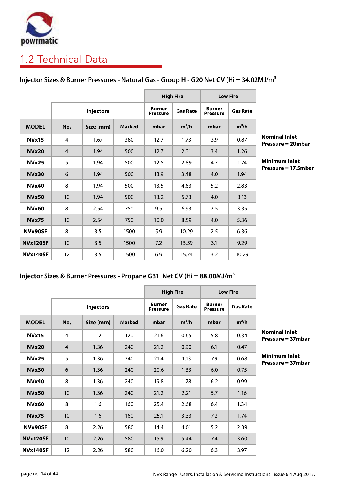
1.2 Technical Data
Injector Sizes & Burner Pressures - Natural Gas - Group H - G20 Net CV (Hi = 34.02MJ/m³
High Fire Low Fire
Injectors
MODEL No. Size (mm)
Burner
Pressure
Marked mbar m ³/h mbar m³/h
Gas Rate
Burner
Pressure
Gas Rate
NVx15 4 1.67 380 12.7 1.73 3.9 0.87
NVx20 4 1.94 500 12 .7 2 .31 3.4 1.26
NVx25 5 1.94 500 12 .5 2.89 4.7 1.74
NVx30 6 1.94 500 13.9 3.48 4.0 1.94
NVx40 8 1.94 500 13 .5 4.63 5.2 2.83
NVx50 10 1.94 500 13. 2 5.73 4.0 3.13
NVx60 8 2.54 750 9.5 6.93 2.5 3.35
NVx75 10 2.54 750 10.0 8.59 4.0 5.36
NVx90SF 8 3.5 1500 5.9 10.29 2.5 6.36
NVx120SF 10 3.5 150 0 7. 2 13 .59 3 .1 9.29
NVx140SF 12 3.5 150 0 6.9 15.74 3.2 10.29
Nominal Inlet
Pressure = 20mbar
Minimum Inlet
Pressure = 17.5mbar
Injector Sizes & Burner Pressures - Propane G31 Net CV (Hi = 88.00MJ/m³
High Fire Low Fire
Injectors
MODEL No. Size (mm)
Burner
Pressure
Marked mbar m ³/h mbar m³/h
Gas Rate
NVx15 4 1.2 120 21. 6 0.65 5.8 0.34
NVx20 4 1. 36 240 21. 2 0.90 6 .1 0.47
NVx25 5 1. 36 240 21.4 1.13 7. 9 0.68
NVx30 6 1.3 6 240 20.6 1.33 6.0 0.75
NVx40 8 1.36 240 19 .8 1. 78 6.2 0.99
NVx50 10 1. 36 240 21. 2 2.21 5.7 1.16
NVx60 8 1.6 160 25.4 2.68 6.4 1. 34
NVx75 10 1.6 16 0 25.1 3.33 7. 2 1. 74
NVx90SF 8 2.26 580 14. 4 4.01 5.2 2.39
NVx120SF 10 2.26 580 15.9 5.44 7. 4 3.60
Burner
Pressure
Gas Rate
Nominal Inlet
Pressure = 37mbar
Minimum Inlet
Pressure = 37mbar
NVx140SF 12 2.26 580 16.0 6.20 6.3 3.97
page no. 14 of 44
NVx Range Users, Installation & Servicing Instructions issue 6.4 Aug 2017.
 Loading...