

Powrmatic NVx10, NVx25, NVx15, NVx20, NVx30 User, Installation And Servicing Instructions
...Page 1
Users, Installation and Servicing
Instructions
WARNING: THIS APPLIANCE MUST BE EARTHED
IMPORTANT: Reset from Lockout is by a switched Neutral
CE
NVx Range Users, Installation & Servicing Instructions Issue 1.9 March 2012
The NVx Range
(Brahma Control)
Page 2
Dear Customer
This is to certify that this heater is guaranteed for two years parts and one year
labour from the date of original commissioning. The heater must be
commissioned within 4 weeks of installation.
The heat exchanger, where fitted, is guaranteed (parts only) for a further eight
years, chargeable on a sliding scale basis, price relative to age.
To make a claim
In the first instance you must contact your appliance supplier, or installer and
provide:-
1. The appliance type and serial number.
2. The original commissioning documentation.
3. As much detail as possible on the fault.
Your supplier, or installer, will then contact Powrmatic to make a guarantee
claim on your behalf.
Conditions of Guarantee
1. The heater must have been installed by a competent recognised installer, and
in accordance with the manufacturers instructions, building regulations and
local regulations.
2. The heater has been professionally commissioned, within 4 weeks of
installation, and a copy of the Commissioning Sheet returned to Powrmatic.
3. The heater has been maintained on a yearly basis by a competent servicing
company.
4. The heater has been used in accordance with the manufacturers instructions.
5. The correct specification fuel has been used
6. No unauthorised repairs or modifications have been made.
7. Powrmatic ‘General Conditions of Sale’ have been observed.
8. Except for the obligation of Powrmatic Ltd to perform warranty repairs during
the guarantee period, Powrmatic will not be liable in respect of any claim for
direct or indirect consequential losses, including loss of profits or increased
costs arising from loss of use of the heater, or any event arising there from.
Exclusions
1. Gaskets and fan belts are not included in the guarantee
Important: This certificate must
be kept with the appliance
Certificate of Guarantee
Powrmatic Ltd, Hort Bridge, Ilminster, Somerset, TA19 9PS
tel: 01460 53535 fax: 01460 52341
web: www.powrmatic.co.uk e-mail: [email protected]
Installed
Date: ___________ Signed______________________________________ Installer
Commissioned
Date: ___________ Signed________________________ Commissioning Engineer
Failure to provide a copy of the Commissioning Sheet invalidates the heater warranty
Page 3

1. Checks before lighting the Air Heater
The following preliminary checks should be made before lighting
the heater(s)
a) Ensure that the ELECTRICAL supply to the heater is
switched OFF.
b) Check that all warm air delivery outlets are open.
c) Check that the thermostat is set at MAX.
d) Check that the clock control is set to an ON period.
e) Check that any other controls are calling for heat.
2. Lighting the Air Heater
NOTE:
On initial lighting of the heater(s), it may take some time to
purge the internal pipe work of air. If it is not possible to light
the heater after several attempts contact the local service
company.
1. Switch on the electrical supply at the isolator and the start up
sequence will commence.
Note: Check that the red overheat indicator on the front of the
unit is not alight. If it is refer to Section 4.4
After a short delay the burners will light and the green ‘ON’
indicator on the front of the heater will be illuminated.
2. If the burners fail to light the control box will automatically
restart the ignition sequence. If after 5 attempts at ignition the
burners have still failed to light the control box will go to lockout
and the lockout light on the low level remote reset (or MC200
or Powrtrol RR if fitted) will be illuminated. To restart the
ignition sequence depress the reset button on the low level reset
for about 1-2 seconds.
If the heater will not light after two or three attempts shut down
the heater and contact a service engineer.
3. To Shut Down the Air Heater
3.1 For Short Periods: Turn the room thermostat to the OFF
or lowest setting.
3.2 For Long Periods: Complete step 3.1 above. Wait for 5
minutes and then turn OFF the
electrical supply at the isolator.
4. Description of Operation
Important: All heaters must be controlled by the fitted external
controls and not by use of the main switch in the electrical
supply to the heater.
4.1 Standard Units
The ignition sequence will commence each time that the external
controls e.g. Time clock, room thermostat etc. call for heat. The
internal exhaust fan will run and when sufficient combustion
airflow is proved by the air pressure switch the ignition spark
will be generated, the main gas valves opened and the burners
lit. The green ‘ON’ indicator will be illuminated. The heater fan
will automatically start approximately 2 minutes after the burners
light. When the external controls are satisfied the burners will
be turned off and approximately 2 - 3 minutes later the heater
fan will be automatically stopped.
4.2 High / Lo & Modulating Units
When the burners are alight the heat output will be controlled
either to high fire or low fire or, in the case of modulating units,
to any point between high and low fire; depending on the
requirements of the space being heated and the external controls
fitted.
4.3 Summer / Winter Modes
Certain types of external controls will provide for two modes
of operation i.e.
Summer: The heater fan alone will run at the dictate of the
external controls to provide air movement.
Winter: The heater will operate normally.
4.4 Overheat Thermostat
This operates if high temperatures within the heater are detected,
the burners are turned off and a red indicator light on the front
panel is illuminated. NVx10 - 75 units have the thermostat
located inside the controls section. NVx90 - 140 units have an
additional thermostat on the side of the unit at the opposite end
to the controls (either thermostat can go to limit and shut off
the burners). The fault condition must be identified and rectified
and the thermostat manually reset.
Isolate the electrical supply to the heater and open the controls
section door. Push in the red button on the fan/limit thermostat
(located towards the top of the compartment) to reset. On NVx90
- 140 units also reset the second limit thermostat.
Note: The thermostat can only be reset once the unit has cooled
down.
Unless the cause of the fault condition is readily obvious, for
example a power cut whilst the heater was operating, a service
engineer should be contacted.
5. Maintenance
To maintain efficient, reliable and safe operation of the heater
it must serviced by a qualified person at least annually and
preferably at the end of the heating season.
6. IMPORTANT
Free access must be maintained to and around the heater for
servicing purposes and the air supply to the heater must not be
restricted in any way. Combustible materials must not be stored
adjacent to the heater.
If at any time a gas leak is suspected turn OFF the gas supply
- DO NOT USE A NAKED FLAME - and contact the local gas
undertaking immediately.
All Powrmatic heaters use gas and electricity to power them,
they may also contain moving parts such as pulleys and belts.
It would be hazardous to tamper with or attempt to service unless
you are a competent person in the field of Gas and Electrical
work.
If you have any safety questions reference the servicing and
installation of any of our heaters please do not hesitate to contact
our head office for expert advice. Your safety is paramount to us.
Gas Safety (Installation & Use) (Amendment) Regulations
It is law that all gas appliances are installed, adjusted and, if
necessary, converted by qualified persons* in accordance with
the current issue of the above regulations. Failure to install
appliances correctly can lead to prosecution. It is in your own
interests and that of safety to ensure that the law is complied
with.
* An approved class of person listed on the gas register.
Users Instructions
Page 4

CONTENTS
Section Title Page
1.
Introduction 1
2. Technical Data 2
3. General Requirements 6
4. Installation 7
5. Air Distribution System 10
6. Commissioning & Testing 10
7. Servicing 12
8. Functional Flow Diagram 15
9. Connections to External Controls 17
10. Fault Finding Flow Chart 19
11. Short List of Parts 20
Tables Title Page
1. Dimensions 3
2. Specifications 3
3. Electrical Loadings 1ph 4
3.1 Injector Sizes & Burner Pressures
Natural Gas - Group H - G20 5
3.2 Injector Sizes & Burner Pressures
Propane - G31 5
Figure Title Page
1a. Exhaust only system - horizontal 8
1b. Exhaust only system - vertical 8
2a. Individual system - horizontal 9
2b. Individual system - vertical 9
3. General Controls Layout 10
4. Governor adjustment (Honeywell VR425A) 11
5. Governor adjustment (Honeywell VR4605A) 11
6. High/Lo Regulator 11
7. Modulating Regulator 12
8. Flame Current Measurement 12
9. Ignition Electrode Spark Gap 13
10. Thermostat Fan / Limit - Honeywell L4064N 13
Installation & Servicing Instructions
Page 5

1. INTRODUCTION
The NVx range are highly efficient gas fired, fanned circulation
air heaters that cover heat outputs of 10kW to 140kW, have a
closed combustion circuit and are supplied complete with a flue
system. They are certified for use on Natural Gas, Group H G20, and Propane - G31 only.
Appliance Categories are Cat II2H3P (GB, IE).
The heaters are designed to be suspended from suitable roof
points or alternatively to be mounted on purpose designed
brackets and are intended primarily for heating commercial or
industrial premises.
NVx heaters feature a closed combustion circuit and have an
internal exhaust fan, mounted downstream of the heat exchanger,
to evacuate the products of combustion and draw in air for
combustion. The air heater must be connected to the flue system
that is provided by Powrmatic Ltd.
They may be used where the atmosphere inside the premises
could be contaminated e.g. Dust, oil mist etc. but the heaters
are not airtight and therefore may not be used in areas classified
as hazardous as defined in BS 5345: Part 2 or areas subjected
to significant negative pressures due to extract systems.
NVx/F heaters have an axial fan assembly fitted at the rear to
circulate the air being heated through the folded tube heat
exchanger. NVx/C units are supplied with a centrifugal fan and
NVx/D units for use with ducted systems where the air moving
fan is by others or a centrifugal fan section is used adjacent to
or remote from the heater. NVx/DH units are for use in air
handling units and NVx/EA units are for siting externally.
Heaters are fitted as standard with inshot burners, a fully
automatic control for ignition, flame sensing, gas supply control
and safety functions, an internal exhaust fan, main air fan (/F
and /C models), and fan/limit thermostat.
Options include High/Low or Modulating burner controls, inlet
duct connection, outlet duct connection, 45° head, 90° outlet
bend, vertical/horizontal outlet louvre assembly and a full range
of modular duct components.
IMPORTANT
Service and Maintenance Engineers shall ensure that replacement
items are fitted, adjusted and set in accordance with the data
and detail set out in these instructions. If in doubt consult
Powrmatic Technical Department.
Gas Safety (Installation & Use) Regulations 1998
It is law that all gas appliances are installed, adjusted and, if
necessary, converted by qualified persons* in accordance with
the current issue of the above regulations. Failure to install
appliances correctly can lead to prosecution. It is in your own
interests and that of safety to ensure that the law is complied
with.
* An approved class of person listed on the gas register.
1
Page 6
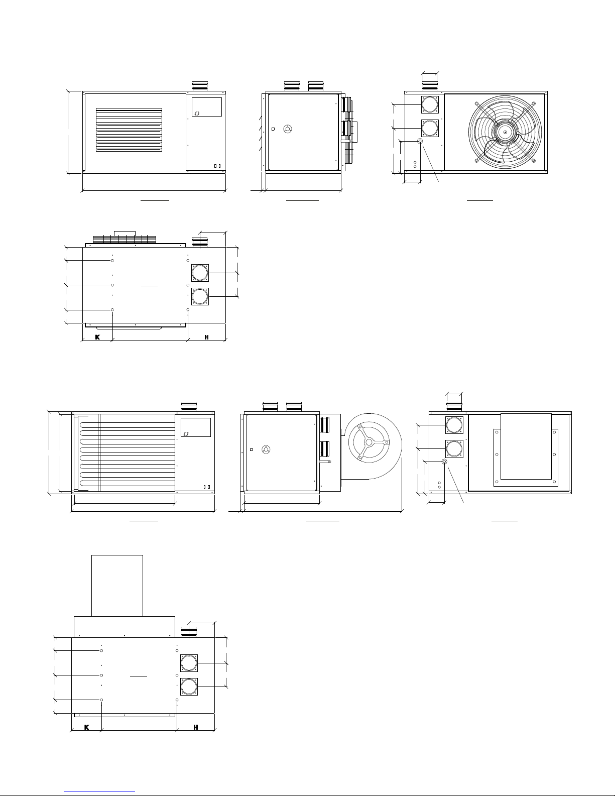
2. TECHNICAL DATA
2
R/H SIDE VIEW
A B
REAR VIEW
PLAN
FRONT VIEW
GAS ENTRY POINT
N
P
F
G
E
G
M
H
J CTRS
K
228 CTRS
228 CTRS
122
122
C
ø D
35
NOTE: For dimensioning purposes both top and rear
flue and combustion air connections are shown
R/H SIDE VIEW
A
REAR VIEW
PLAN
FRONT VIEW
N
P
F
G
E
G
M
H
J CTRS
K
228 CTRS
228 CTRS
122
122
C
ø D
35
NOTE: For dimensioning purposes both top and rear
flue and combustion air connections are shown
L
B
T
S
NVx
POWRMATIC
NVx
POWRMATIC
GAS ENTRY POINT
Page 7
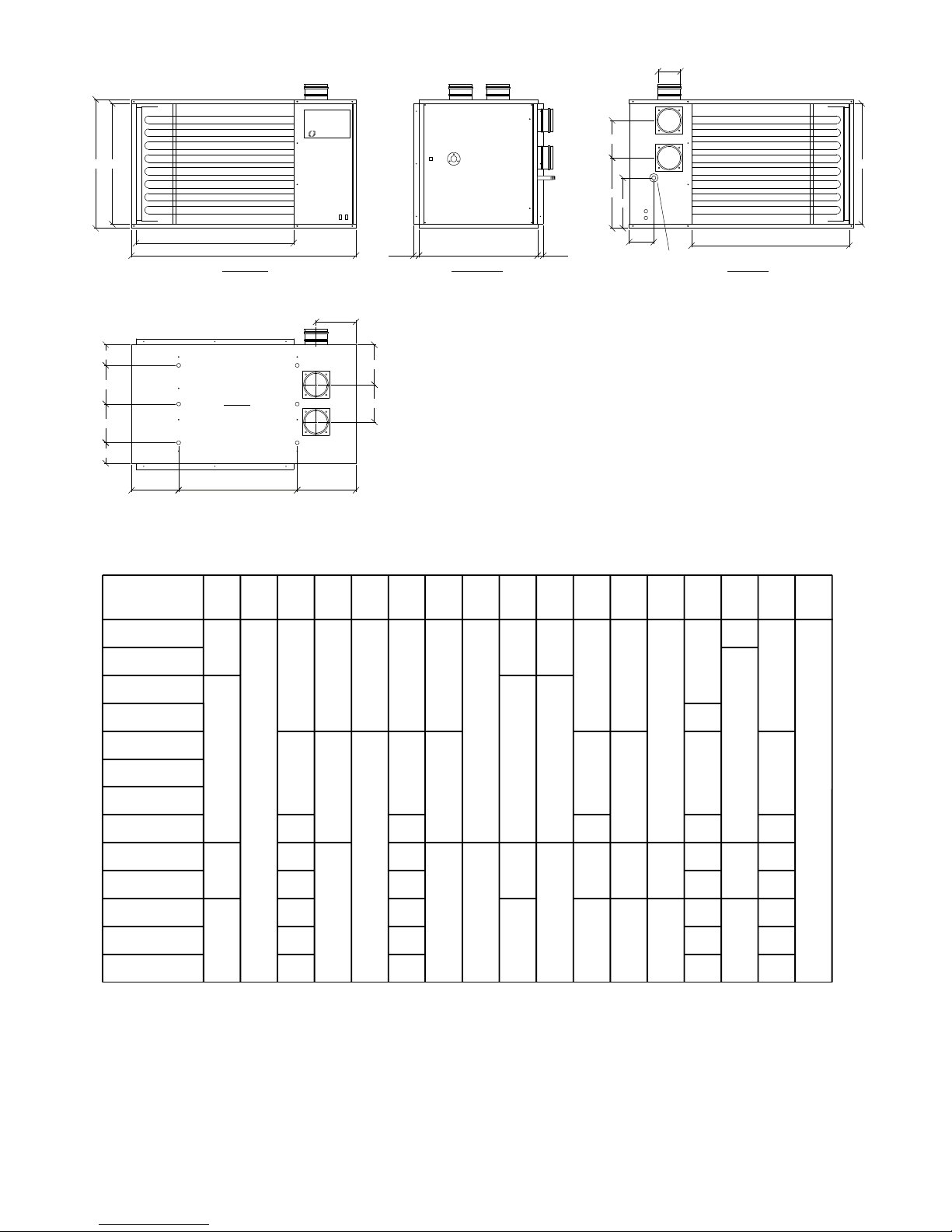
NOTE: For dimensioning purposes both top and rear
flue and combustion air connections are shown
33.733.7
T
S
R/H SIDE VIEW
A
S
REAR VIEW
PLAN
FRONT VIEW
N
P
F
G
E
G
M
H
J CTRS
K
B
228 CTRS
228 CTRS
122
122
C T
ø D
NVx
POWRMATIC
GAS ENTRY POINT
Table 1. Dimensions
3
NVx
15
NVx
25
NVx
30
NVx
50
NVx
60
NVx
75
NVx
90
NVx
120
NVx
140
NVx
35
Model
NVx10
B
700
A
1000
1325
2325
785
C
540
760
912
912
700
760
831
975
422
637
932
1932
492
712
864
864
652
712
783
927
ØD E
233.5
24880
100
130
F
492
644
416
568
321
487
631
308
G
142
220
120
H
347
317
J
450
700
850
250
M
236
246
206
216
L
524
752
904
752
904
639
804
969
K
218
232.5
278
NVx
20
NVx
40
N
114
145
88
P
¾'’
194
225.5
297
374
374
260
326
398
297
S T
Gas
inlet
Ø
Page 8

Table 3
Electrical Loadings 1ph
NVx
90
NVx
120
7.81 4.22
9.57 5.13
NVx
140
9.64 4.98
/F Models /C Models
MODEL
PLATE
AMPS
(A)
START
AMPS
(A)
RUN
AMPS
(A)
FUSE
RATING
(A)
NVx
10
2
NVx
15
0.18 0.34 0.16
870
2.8 4.2 2.10
1.39 0.51 4.0 8.1 2.60
NVx
20
0.38 0.28 4.0 7.8 3.20
3
NVx
30
1.83 0.61 14.7 4.50
7
NVx
40
1.30
2.56
1.35 8.4
14.5 5.00
NVx
50
1.40 4.01 1.96 3 16.0 6.40
NVx
60
4.70 2.44
NVx
75
4.78 2.51
2 x 1.40
NOMINAL
MOTOR
R.P.M.
PLATE
AMPS
(A)
START
AMPS
(A)
RUN
AMPS
(A)
FUSE
RATING
(A)
NVx
25
1.89 0.62
0.54
0.89
2.50
2 x 2.50
0.31
7
5
NOMINAL
MOTOR
R.P.M.
4.0 8.2 2.90
28.4 11.6
25
900
1400
775
910
820
900
11.1
2 x 8.4
2 x 11.1
24.5 10.6
42.5 21.5
24.5 12.3
16
NVx
35
Note: 3ph Data is
supplied separately with
units ordered to this
specification.
14.0
39.8
5.30
25.2
5
Table 2 - Specifications
4
Note: /D data refers to Powrmatic supplied centrifugal/silencer duct section
MODEL
INPUT
(Nett)
OUTPUT
INPUT
(Nett)
OUTPUT
kg
kW kW m³/s m³/h Pa kW
NVx10
10.79 10.0 6.57 5.90 0.2601
NVx15
16.00 15.0 8.22 7.50 0.3902
NVx20
21.85 20.0 11.58 9.92 0.5203
NVx25
27.32 25.0 16.50 14.30 0.6503
NVx30
32.60 30.0 18.34 16.30 0.7804
NVx40
43.48 40.0 24.19 21.22 1.0405
NVx50
54.23 50.0 28.40 24.83 1.3006
N/A 0.040 53
140
0.250
91.5
N/A
0.120
59.5
145 0.370 106.5
N/A 0.070 69.5
177 0.370 120.5
N/A 0.180 74.5
143 0.370 126.5
N/A 0.180 96.0
250 1.100 166.5
N/A 0.300 108.0
236 1.100 168.5
N/A 0.440 123.0
205 1.100
183
F
D
F
D
F
D
F
D
F
D
F
D
F
D
HIGH FIRE LOW FIRE
AIR
VOLUME
MAXIMUM
DUCT
RESISTANCE
FAN
MOTOR
WEIGHT
NVx60
65.22 60.0 35.63 31.49 1.5608
N/A 0.550 138.5
250 1.50
213
D
F
F
D
F
D
D
F
NVx75
NVx90
NVx120
81.5 75.0
97.8 90.0
130.4 120.0
42.61 37.50
58.50 54.50
75.45 71.00
1.9510
2.3412
3.1215
N/A 0.550 158.0
260 1.50 234
N/A 2 x 0.440 204.0
200 2 x 1.10 343
N/A 2 x 0.550 260
284 2 x 1.50 363.5
D
F
NVx140
152.1 140.0 98.92 92.55 3.6418
N/A 2 x 0.550 260
285 2 x 1.50 424
NOISE
LEVEL
dB(A) @ 3m
N/A
N/A
N/A
N/A
N/A
N/A
N/A
N/A
N/A
N/A
N/A
N/A
46
54
52
53
54
58
61
62
62
66
67
67
NVx35
F
D
39.32 34.95 23.1 19.0 1.000
936
1405
1873
2341
2809
3746
4682
5619
7024
8428
11237
13110
3600
N/A 0.300 96.0
210 1.100 166.5
N/A
58
Page 9
Minimum
Inlet pressure
17.5mbar
Inlet
INJECTORS
High Fire
Low Fire
Pressure Burner
Gas Rate
Burner
Gas Rate
20mb Pressure Pressure
MODEL No. Size Marked mbar m³/h mbar m³/h
mm
NVx10 4 1.36 240 13.8 1.14 5.3 0.69
NVx15 4 1.67 380 12.5 1.69 3.5 0.87
NVx20 4 1.94 500 12.7 2.31 3.4 1.26
NVx25 5 1.94 500 12.5 2.89 4.7 1.74
NVx30 6 1.94 500 13.6 3.45 4.0 1.94
NVx35 6 2.26 580 9.5 4.16 4.0 2.44
NVx40 8 1.94 500 13.5 4.60 4.0 2.56
NVx50 10 1.94 500 13.2 5.74 4.0 3.00
NVx60 8 2.54 750 9.5 6.90 2.5 3.47
NVx75 10 2.54 750 9.2 8.60 2.8 4.50
NVx90 6 3.5 1500 9.4 10.08 3.5 6.19
NVx120 8 3.5 1500 9.1 13.37 3.4 7.98
NVx140 10 3.5 1500 8.4 15.76 4.0 10.46
Inlet Pressure
37mbar
5
Table 4.1
Injector Sizes & Burner Pressures Natural Gas - Group H - G20 Net CV (Hi) = 34.02MJ/m³
Table 4.2
Injector Sizes & Burner Pressures - Propane G31 - Net CV (Hi) = 88.00MJ/m³
Inlet
INJECTORS
High Fire
Low Fire
Pressure Burner
Gas Rate
Burner
Gas Rate
37mb Pressure Pressure
MODEL No. Size Marked mbar m³/h mbar m³/h
mm
NVx10 4 0.90 90 24.4 0.44 N/A N/A
NVx15 4 1.20 120 21.6 0.65 5.8 0.34
NVx20 4 1.36 240 21.2 0.89 6.1 0.49
NVx25 5 1.36 240 21.4 1.12 7.9 0.67
NVx30 6 1.36 240 20.6 1.33 6.0 0.75
NVx35 6 1.36 240 20.5 1.61 9.2 0.95
NVx40 8 1.36 240 19.8 1.78 6.2 0.99
NVx50 10 1.36 240 21.2 2.22 5.7 1.16
NVx60 8 1.60 160 25.4 2.67 6.4 1.34
NVx75 10 1.60 160 25.1 3.32 7.2 1.74
NVx90 6 2.26 580 21.0 3.90 7.9 2.39
NVx120 8 2.26 580 21.1 5.17 7.7 3.08
NVx140 10 2.26 580 20.2 6.09 8.6 4.04
Page 10

3. General Requirements
3.1 Related Documents
The installation of the air heater(s) must be in accordance with
the rules in force and the relevant requirements of the Gas Safety
Regulations, Building Regulations and the I.E.E. Regulations
for Electrical Installations.
It should also be in accordance with any relevant requirements
of the local gas region, local authority and fire authority and
the relevant recommendations of the following documents.
Institution of Gas Engineers & Managers
IGE/UP/1 (Ed.2) Strength and tightness testing and purging of
industrial and commercial gas installations.
IGE/UP/1A Soundness testing and direct purging of small low
pressure industrial and commercial gas installations.
IGE/UP/2 Gas installation pipe work, boosters and compressors
on industrial and commercial premises.
IGE/UP/10 (with Amendments October 2010) Installation gas
appliances in industrial and commercial premises.
British Standards Code of Practice
BS 5588 Fire precautions in the design and construction of
buildings.
Part 2 : 1985 Code of Practice for Shops
Part 3 : 1983 Code of Practice for Office Buildings
BS 6230 Installation of Gas Fired Forced Convection Air Heaters
for Commercial and Industrial Space Heating.
Those appliances having a gross input rating not exceeding
60kW viz. NVx10 to NVx50 inclusive and installed to take their
combustion air from within the building must be installed in
accordance with the relevant recommendations of the following
document.
BS 5440 Flues and Air Supply for gas appliances of rated input
not exceeding 60kW (1st and 2nd family gases), Part 2 - Air
Supply
For NV/D units of 10 - 50 size, reference should also be made
to
BS 5864 Code of Practice for installation of gas-fired ducted-air
heaters of rated input not exceeding 60kW.
3.2 Location
The location chosen for the air heater must permit:
- provision of a satisfactory flue system and adequate air supply.
- adequate space for servicing and air circulation around the air
heater.
IMPORTANT:
1. Heaters shall not be installed in:a) Those parts of spaces within buildings that have been classified
as hazardous areas as defined in BS EN 60079-10, Electrical
apparatus for explosive gas atmospheres. Classification of
hazardous areas.
b) Where there is a foreseeable risk of flammable particles or
gases or corrosion inducing gases or vapours being drawn into
either the heated air stream or the air for combustion. In such
cases installation may only proceed if the air to be heated is
ducted to the heater from an uncontaminated source, preferably
from outside the building. The option of taking combustion air
from the space is not permitted. Where only airborne particles
are present it may suffice to fit filters on the main air inlet duct
of the heater and advice may be obtained from Powrmatic Ltd.
c) Particular care should be taken to ensure chlorine vapours
(from Freon, degreaser compounds etc.) are not induced into
the combustion air stream as severe heat exchanger damage will
result.
d) In areas subjected to significant negative pressures due to
extract systems.
Where the location of the air heater is such that it might suffer
external mechanical damage e.g. from overhead cranes, fork
lift trucks, it must be suitably protected.
NVx units are designed to operate within an ambient temperature
range of -10 to 25°C.
3.3 Gas Supply
3.3.1 Service Pipes
The local gas undertaking should be consulted at the installation
planning stage in order to establish the availability of an adequate
supply of gas. An existing service pipe must not be used without
prior consultation with the local gas undertaking. The inlet gas
pressure under running conditions must not be less than 17.5mb.
3.3.2 Meters
An existing meter should be checked, preferably by the gas
undertaking, to ensure that the meter is adequate to deal with
the total rate of gas supply required by all connected equipment.
3.3.3. Installation Pipes
Installation pipes should be fitted in accordance with
IGE/UP/2. Pipe work from the meter to the air heater must be
of adequate size. Do not use pipes of a smaller size than the
inlet gas connection of the heater. The complete installation
must be tested for soundness as described in the above Code.
3.3.4. Boosted Supplies
Where it is necessary to employ a gas pressure booster the
controls must include a low pressure cut off switch at the booster
inlet. The local gas undertaking must be consulted before a gas
pressure booster is fitted.
3.4 Flue System
Only flue systems supplied through Powrmatic Ltd may be used
with NVx units and they comprise of Muelink & Grol terminals
and twin to concentric adapters and SFL SUPRA straight lenghts
and elbows.
Several configurations of flue and combustion air ducts are
available (See Page 7 & 8 Figs 1a to 2b).
The flue must terminate in a freely exposed position and be
sited to prevent the products of combustion entering any opening
in a building in such concentration as to be prejudicial to health
or a nuisance.
3.5 Combustion Air Supply
Air inlet grilles shall be provided at low level when combustion
air is taken from within the space being heated and the building
has a design air change rate less than 0.5/h, and NVx units are
installed in heated spaces having a volume less than 4.7 m³/kW
of total rated heat input:(1) for heaters of heat input less than 60 kW, the total
minimum free area shall not be less than 4.5 cm² per
kilowatt of rated heat input.
(2) for heaters of heat input 60 kW or more, the total
minimum free area shall not be less than 270cm² plus
2.25 cm² per kilowatt in excess of 60 kW rated heat input.
Where the air heater(s) are to be installed in a plant room the
plant room must have permanent air vents communicating
directly with the outside air, at high level and at low level. Where
communication with the outside air is possible only by means
of high level air vents, ducting down to floor level for the lower
vents should be used.
All air vents should have negligible resistance and must not be
sited in any position where they are likely to be easily blocked
or flooded or in any position adjacent to an extraction system
which is carrying flammable vapour.
Grilles or louvres should be so designed that high velocity air
streams do not occur within the plant room.
The basic minimum effective area requirements of the air vents
6
Page 11

7
4. Installation of Air Heater(s)
4.1 General
Before installation
1) Check that the local distribution conditions, nature of gas
and pressure, and adjustment of the appliance are compatible.
2) Check that the local electrical supply conditions are
compatible with the electrical data given on the data plate.
For NVx/D units the normal air flow direction is from right to
left when viewing the heater from the burner/controls end with
the fan unit upstream.
The following minimum clearances must be observed for
installation and servicing .
RHS Clearance (looking at front of heater) 1.0m
LHS Clearance (looking at front of heater) 0.2m
Top of the heater to ceiling 0.2m
Rear of heater to nearest wall 0.4m
(Depending on flue system used)
For multi air heater installations the following minimum
distances between units must be observed.
Between units, side to side 3.0m
Between units, back to back 3.0m
Recommended mounting heights, floor level to the underside
of the unit, are:NVx10 - 30F 2.5m - 3m
NVx40F - 150F 3m - 5m
NVx/D Models Mounting heights not applicable
All models must not be installed at a height of less than 2.5m
to the base of the unit.
Any combustible material adjacent to the air heater and the flue
system must be so placed or shielded as to ensure that its
temperature does not exceed 65 °C.
When NVx modular components are used in conjunction with
the heater each component must be individually supported.
4.2 Fitting the Air Heater
Note: The access door to the controls section may be removed
to improve access. Open the door to 90°, remove the earth cable
at the bottom, and then lift the door vertically upwards to
disengage the hinge plates. Refit in reverse order. Ensure that
the earth cable is refitted.
The air heater may be installed either:
a) suspended from suitable vertical drop rods or chains.
b) on specifically designed cantilever brackets from a
noncombustible wall.
c) on a level noncombustible surface. The surface must
not extend past the front edge of NVx/F heaters.
The method of installation must be capable of adequately
supporting the weight of the unit (See Table 2, Page 3) and any
ancillary equipment. Before installing the heater the existing
structure must be inspected to ensure it is suitable. All supports
should be protected against the effects of rust or corrosion.
Raise the heater up to the point of installation using suitable
and safe means and connect to the means of suspension.
Note: Each heater is provided with additional central suspension
points that can be used to provide temporary support, using
suitable means, whilst the unit is being installed. Under no
circumstances must these points be used as the final means of
suspension.
Threaded drop rods must have lock nuts fitted that are tightened
down onto the 10mm fixings in the heater.
If reducing noise levels is important the heater should be
insulated from the structure by installing it on suitable
anti-vibration mountings. In all such cases and when the heater
is suspended it is essential that all gas, duct, and electrical
are as follows:
(a) Low Level (inlet)
(1) for heaters of total rated heat input less than 60kW:
9cm² per kilowatt of rated heat input.
(2) for heaters of total rated heat input 60kW or more:
540 cm² plus 4.5 cm² per kilowatt in excess of 60
kW total rated input.
(b) High Level (outlet)
(1) for heaters of total rated heat input less than 60kW:
4.5cm² per kilowatt of rated heat input.
(2) for heaters of total rated heat input 60kW or more:
270 cm² plus 2.25 cm² per kilowatt in excess of 60kW
total rated input.
3.6 Air Distribution System
Where single NVx/F units are required to cover a large floor
area, and in buildings with high roof or ceiling heights Calecon
thermal economiser units should be fitted to ensure even heat
distribution and minimise stratification.
Care should be taken to avoid impeding the air throw with
racking, partitions, plant or machinery etc. Various outlet
configurations are available as optional extras to modify the air
throw pattern to suit particular site conditions.
For ducted units all delivery and return air ducts, including air
filters, jointing and any insulation or lining must be constructed
entirely of materials which will not contribute to a fire, are of
adequate strength and dimensionally stable for the maximum
internal and external temperatures to which they are to be
exposed during commissioning and normal operation.
Where inter-joist spaces are used as duct routes they should be
suitably lined with a fire-resisting material.
A full and unobstructed return air path to the air heater(s) must
be provided.
If the air heater(s) is installed in a plant room the return air
intake(s) and the warm air outlet(s) from the heater(s) must be
fully ducted, into and out of the plant room to avoid interference
with the operation of the heater.
The openings in the structure of the plant room through which
the ducting passes must be fire stopped.
Care must be taken to ensure that return-air intakes are kept
clear of sources of smells and fumes, and where there is any
possibility of pollution of the air by dust, shavings etc.,
precautions must be taken to prevent contamination.
If necessary suitable barrier rails should be provided to prevent
any combustible material being placed within 900mm of the
outlets.
3.7 Electrical Supply
Wiring external to the air heater must be installed in accordance
with the I.E.E. Regulations for Electrical Installations and any
local regulations which apply.
All standard heaters are supplied by 230V - 1ph, 50Hz. The
method of connection to the main electricity supply must:-
- facilitate the complete electrical isolation of the unit(s)
- be in a readily accessible position adjacent to the unit(s)
- serve only the unit(s)
- have a contact separation of at least 3mm in all poles. See the
accompanying wiring diagram for the heater electrical
connections
NVx/C and fan/silencer units can also be supplied for 400V 3N,
50Hz.
Page 12
8
connections to the heater are made with flexible connections to
maintain continuity of connection.
4.3 Flue/Combustion Air Duct System
The minimum distance between surfaces of the flue pipe and
any surfaces made from combustible materials is 300mm. If it
is necessary for the flue pipe to bass through a structure made
from combustible materials a metal sleeve must be used so that
the minimum clearance of 300mm is maintained. The flue and
combustion air ducts supplied with the heater are capable of
withstanding their own weight over the allowable flue lengths.
Wall bands and bracing brackets, or equivalent, must be used
to provide lateral stability and should be used at centres not
exceeding 2.5 metres.
All models are supplied as standard with a rear flue outlet and
the flue outlet and combustion air sockets temporarily fitted.
4.3.1.1. Conversion to Top Flue Outlet
1. Remove the two blanking plates from the flue /combustion
air openings at the top of the unit.
2. Remove the four screws from the exhaust fan outlet flange.
3. Remove the screws securing the fan mounting box to the
exhaust header plate.
4. Remove fan assembly and rotate the assembly 90°
anticlockwise.
5 Refit the fan assembly to the exhaust header plate ensuring
that the gasket is not damaged, if necessary replace or make
good with silicon sealant.
6. Secure the exhaust fan outelt flange to the underside of the
top panel and fit the blanking plates to the rear panel.
4.3.1.2 Fitting Flue/Combustion Air Sockets
1. Apply a bead of silicon sealant around the face of the flange
on the exhaust fan outlet tube that can be seen from the outside
of the heater. Place the flue socket on the outside of the heater
to mate with this flange and clamp the two flanges together, on
either side of the heater panel using the screws provided. Ensure
that the silicon sealant has sealed between the two flanges.
2. Apply a bead of silicon sealant around the face of the flange
of the combustion air socket, on the same side as the socket.
Passing the socket through the panel from the inside, position
the flange up against the panel. Secure, from the outside, with
the screws provided.
3. If ducted combustion air is not required (see Section 3.5) fit
the mesh inlet plate behind the unused combustion air inlet hole.
4. Apply silicon sealant and refit blanking plates as required to
seal unused panel holes.
4.3.2. General Requirements
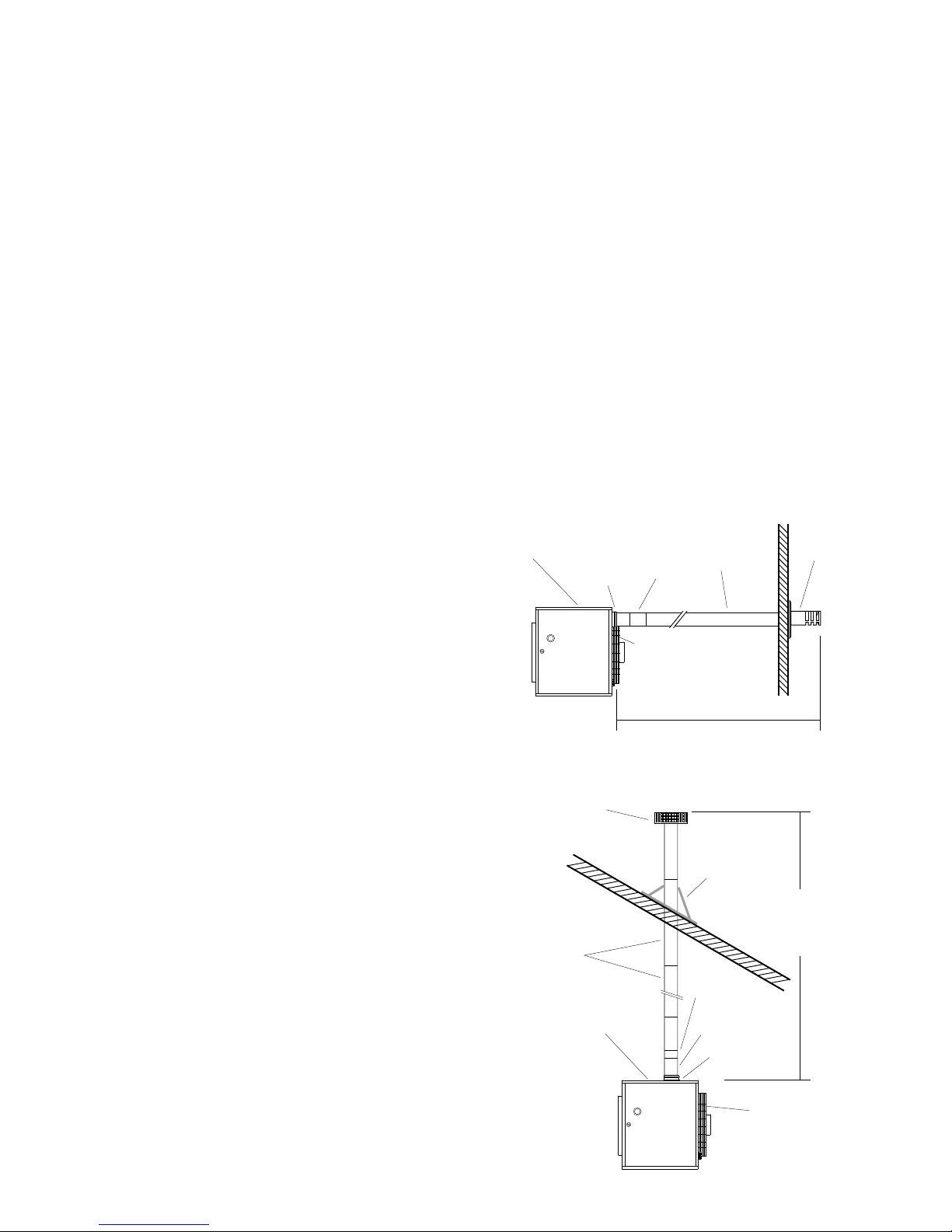
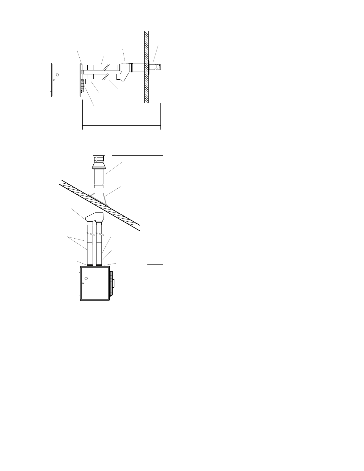
See Figures 1a to 2b for the different types of flue installation.
In all cases the flue outlet socket must be connected via the
provided flue system to outside air. The maximum permitted
length of flue system is 6m, or 12m if the flue outlet only is
used. If an offset is required two sets of 45° bends should be
used each set being equivalent to 0.5m of flue length. 90° bends
may be used but each set will be equivalent to 1.0m of flue
length. The minimum flue length (end of flue terminal to back
or top of heater) shall not be less than 1.0m for the NVx10 - 50
and 1.3m for the NVx60 - 140.
All outer joints must be finished with the provided locking
bands. A smear of silicon grease to the inside of sockets will
assist in fitting components together. All flue and combustion
air ducts must be supported independently of the air heater. The
flue or flue/combustion air terminal must not be installed so as
to be less than:
- 300mm below an opening e.g. window, air brick etc.
- 200mm below eaves or gutter.
- 300mm from an internal or external corner.
- 1200mm from a surface facing the terminal.
- 1500mm vertically from another terminal on the same wall.
- 300mm horizontally from another terminal on the same wall.
- 2000mm from ground level.
4.3.3 Installation of Flue System
Note: A terminal guard, as supplied by Powrmatic Ltd, must be
fitted to horizontal flue terminals. The minimum flue length in
all cases is
4.3.3.1 Horizontal System - Rear Outlet
Note: If the outlet is required to the side of the unit 90° bends
may be fitted directly onto the inlet/outlet spigots on the heater.
1. Locate the position of the flue terminal, allowing for a slight
gradient running down from the heater to the terminal of 2° 3° and cut a hole to suit.
2. Fit the flue terminal, securing via the wall plate and weather
with silicon sealant or similar.
3. Fit the twin to concentric adaptor to the terminal section and
extend the flue and combustion air ducts to the heater using
straight lengths. Fit an adjustable length prior to the unit, to
facilitate flue disconnection for servicing. Extend the adjustable
lengths to make the final connection to the appropriate heater
inlet/outlet spigots.
4. Ensure that internal silicon sealing rings are in place and that
all tubes are pushed fully home. Secure concentric lengths with
Fig 1b Exhaust only system - vertical
Terminal
Lengths
Adjustable
length
Flashing
Flue
socket
Combustion air entry
(fitted with inlet grille)
Condensate drain
length
Fig 1a Exhaust only system - horizontal
Terminal
Lengths
Adjustable
length
Flue
outlet
Combustion air entry
(fitted with inlet grille and
inlet bend (not shown))
12m maximum, Minimum 980mm
Combustion air entry
(fitted with inlet grille)
Note: A terminal guard may be required.
Combustion air entry
(fitted with inlet grille and
inlet bend (not shown))
Maximum 12m
Minimum
80Ø - 1480mm
100Ø - 1560mm
130Ø - 1860mm
Page 13
9
the locking bands provided.
4.3.3.2 Vertical System - Top Outlet
1. Locate the position of the flue terminal cut a hole in the roof
to suit.
2. Fit the flashing and the flue terminal so that the lower edge
of the outer case is over the top of the flashing. Weather with
silicon sealant or similar.
Fit a condensate drain length into the flue socket on the heater
and an equivalent straight length onto the combustion air socket.
3. Fit the twin to concentric adaptor to the terminal section and
Notes for all systems.
i) Final overall length of adjustable disconnection piece must be
between 360 - 415mm.
ii) 45° offsets may be used if required. Each set is equivalent to
0.5m of flue length.
iii) Where NV heaters are used in clean environments it is
permissible to take the combustion air directly from the heated
space. The supplied mesh intake plate, must be fitted to the
combustion air inlet on the rear of the heater.
then extend down to the heater using straight lengths. Fit
adjustable lengths as the final connection pieces, to facilitate
flue disconnection for servicing. Extend the adjustable lengths
to make the final connection but do not exceed the maximum
extended length so as to maintain joint integrity.
Extend the drainage off take of the condensate drainage length
to a suitable gully or drain.
4. Ensure that internal silicon sealing rings are in place and that
all tubes are pushed fully home. Secure concentric lengths with
the locking bands provided.
4.3.3.3 Internal Combustion Air Systems
1. Complete the run of flue sections from the terminal spigot to
the flue outlet socket of the heater generally as described in
4.3.3.1 and 4.3.3.2, ensuring that the internal silicon sealing
rings are in place.
2. It is recommended that both air inlets are utilised and that
both are fitted with the mesh inlet plates supplied. In addition
a 90° bend should be fitted to the rear inlet, the inlet opening
of the bend facing to the side of the heater i.e. away from the
main air fan.
4.4 Gas Connection
A servicing valve and union to facilitate servicing must be fitted
to the gas inlet pipe work of the heater. The gas supply must be
completed in solid pipe work and be adequately supported.
Heaters suspended by drop rods, straps or chains must have a
flexible connection as the final link between the gas supply pipe
work and the heater. Sufficient slack must be left in the
connection to take account of normal movement of the heater.
Warning
When completing the final gas connection to the heater do not
place undue strain on the gas pipe work of the heater.
4.5 Electrical Connections
All units, with the exception of NVx/D units supplied with a
centrifugal fan/silencer duct section, are fully prewired and only
require final connections for the incoming mains supply and
completion of the control circuit (230V) via a room thermostat,
time clock etc. and the remote low level lockout reset.
Warning: Lockout reset is by a switched Neutral to the controls
in the heater.
All units must be earthed. See Table 4 (Page 4) to ascertain the
electrical loading of the unit(s) so that cables of adequate
cross-sectional area are used for the electrical installation. The
length of the conductors between the cord anchorage and the
terminals must be such that the current carrying conductors
become taut before the earth conductor if the cable or cord slips
out of the cord anchorage. All external controls must be of an
approved type.
See the wiring diagram accompanying these instructions.
NVx/D models supplied with a centrifugal fan/silencer duct
section require wiring to be completed between the heater and
fan. Refer to supplied wiring diagram.
NVx/D models supplied less fan must be electrically interlocked
to the air movement system so that this is started in the same
manner as the air heater fan would be viz. A connection from
the heater terminal marked “Live Main Fan” must be made to
one side of the fan motor contactor coil, the other side of the
coil being connected to Neutral. The fan motor electrical supply
must not be taken direct from the internal wiring of the NVx
heater.
Fig 2b Individual system - vertical
Maximum 6m
Minimum
80Ø - 1480mm
100Ø - 1560mm
130Ø - 1860mm
Terminal
Lengths
Adjustable
lengths
Single to twin
adaptor
Flashing
Flue socket
Combustion air
socket
Condensate drain
length
Fig 2a Individual system - horizontal
Terminal
Lengths
Adjustable
length
Single to twin
adaptor
Flue socket
Combustion
air duct
Maximum 6m, Minimum 980mm
Combustion
air socket
Note: A terminal guard may be required.
Page 14
10
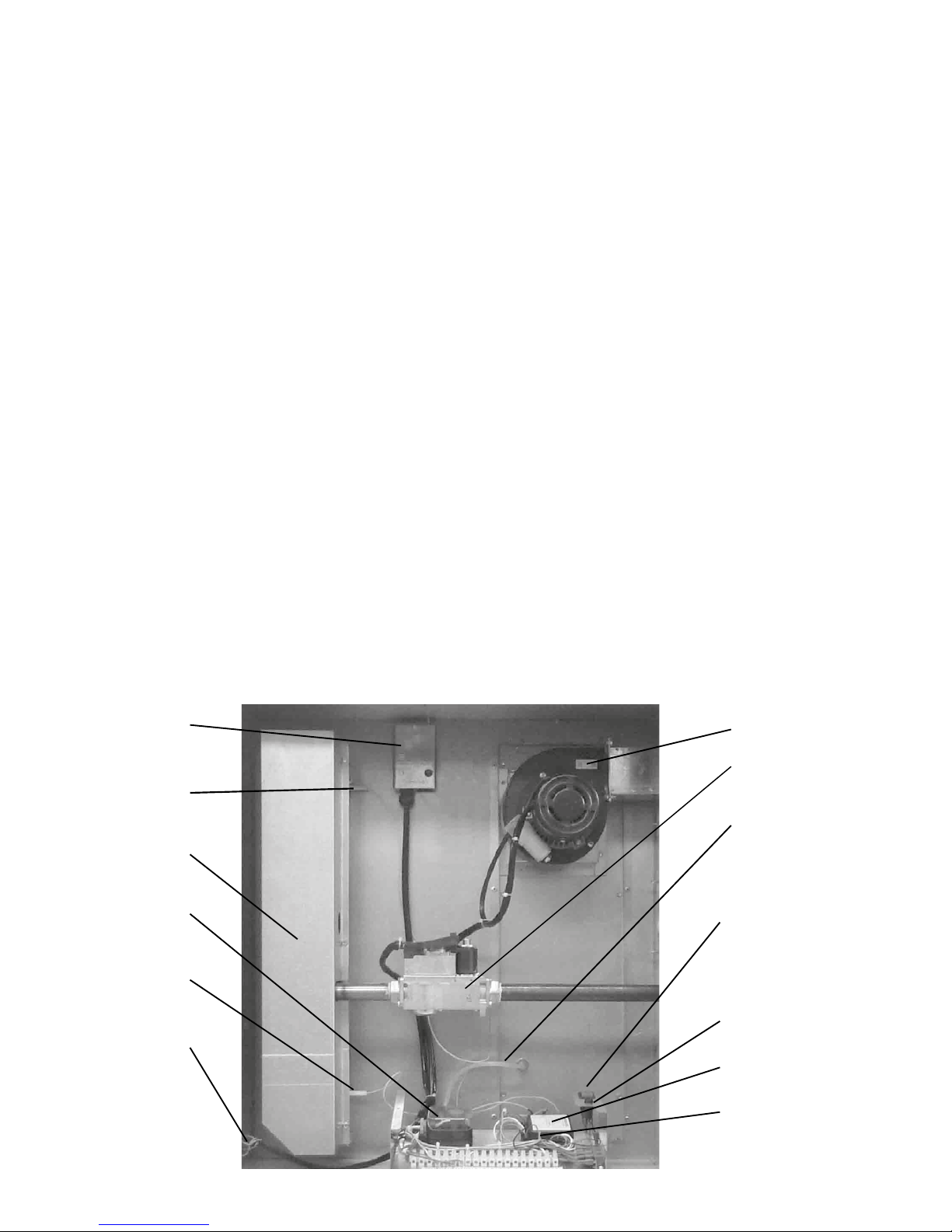
Figure 3 General Controls Layout
Exhaust
Fan (F)*
Burner
Assembly
Fan/Limit
Thermostat (B)*
Brahma
Control (A)*
Main Fuse
(3.15A) (L)*
Brahma
Control
Fuse (4A)
Gas
Valve (E)*
Ignition
Electrode (J)*
On (O)* and
limit indicator
lights (C)*
Rectification
Electrode (J)*
Internal
lockout
indicator
and reset
switch (N)*
Air Pressure
Switch (APS)
(D)*
* Refers to
functional flow
diagrams
APS
Sensing
Tube
5. Air Distribution System
5.1 General
NVx/D and NVx/C models are designed for use with duct work
to more precisely define the point of air delivery, and /or provide
ducted return air or ducted fresh air inlet. All ducting must be
independently supported of the air heater.
Joints and seams of supply ducts and joints between NVx
ancillary components must be securely fastened and made
airtight using appropriate sealants or sealing strips. If required
the duct work should be insulated to reduce heat loss.
5.2 Noise Reduction
Ducting should be connected to the heater spigots via an airtight
flexible coupling of noncombustible material. Before fitting the
coupling it must be ensured that a minimum clearance of
approximately 15mm will be maintained between the ends of
the ducting and the heater spigots.
Sound attenuators may be fitted in inlet and outlet ducts to
reduce airborne fan noise. Materials used in outlet sound
attenuators must be capable of withstanding 100°C air
temperature without any deterioration.
5.3 Room Thermostat Siting
The room thermostat should be fitted at a point which will be
generally representative of the heated area as far as temperature
is concerned. Draughty areas, areas subjected to direct heat e.g.
from the sun, and areas where the air movement is relatively
stagnant e.g. in recesses, should be avoided.
The thermostat should be mounted about 1.5m from the floor.
Any room thermostat, frost thermostat, time clock etc. must be
suitable for switching 230V, 5A and must be of the 'snap action'
type to minimise contact bounce.
For electrical connections of external controls see the
accompanying wiring diagram.
6. Commissioning & Testing
6.1 Electrical Installation
Checks to ensure electrical safety must be carried out by a
qualified person.
6.2 Gas Installation
For new installations the whole of the gas installation, including
the meter, should be inspected and tested for soundness and
purged in accordance with the recommendations of IGE/UP/1
(Edition 2) or IGE/UP/2A as appropriate.
6.3 Air Distribution System
The system should be checked to ensure that the installation
work has been carried out in accordance with the design
requirements.
Particular attention should be given to the correct arrangement
of delivery ducts and registers, return air ducts and grills and
general adequacy of return air paths.
For NVx/D and NVx/C units ensure that the duct work is
balanced so that the specified motor running currents are
achieved See Table 3, Page 4.
6.4 Checks before lighting the Air Heater
The following preliminary checks should be made before lighting
the heater(s)
a) Ensure that the ELECTRICAL supply to the heater is
switched OFF.
b) Check that all warm air delivery outlets are open.
c) Check that all external controls are calling for heat.
d) If an MC200 or Powrtrol is being used ensure that the
control is set to Winter operation.
Page 15
11
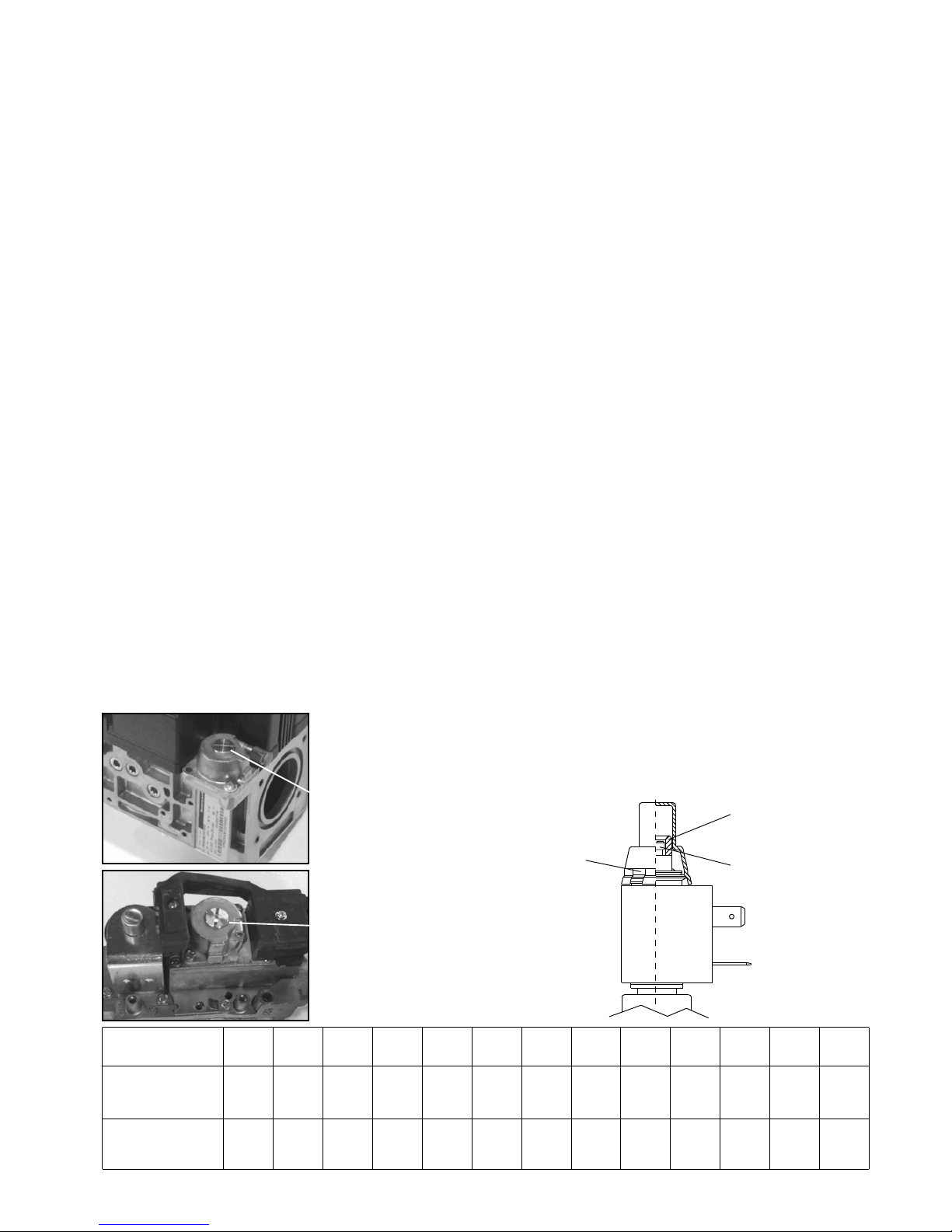
Figure 4
Governor adjustment
screw under cover cap
(Honeywell
VR425AB1007)
Figure 5
Governor adjustment
screw under cover cap
(Honeywell VR4605A
B1027)
NVx NVx NVx NVx NVx NVx NVx NVx NVx NVx NVx NVx NVx
Model 10 15 20 25 30 35 40 50 60 75 90 120 140
Natural Gas G20
High Fire CO2% 6.7 7.3 7.4 7.3 7.8 8.25 7.7 8.7 8.1 8.8 7.4 8.7 8.3
Low Fire CO2% 3.7 3.1 3.2 3.7 3.7 3.6 3.6 3.5 3.4 3.6 3.9 4.4 4.6
Propane G31
High Fire CO2% 7.3 7.9 8.5 8.1 9.1 9.2 9.3 9.5 9.1 9.7 8.5 10.1 8.0
Low Fire CO2% 4.1 3.8 3.7 4.1 4.1 3.9 4.3 4.0 3.9 4.1 4.5 5.0 4.0
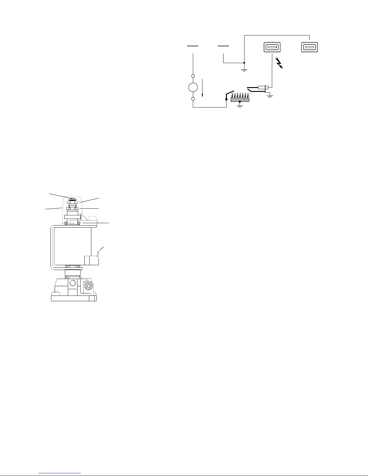
Fig 6 High/Low Regulator
Cover
Lever point
Hexagonal
adjustment screw for
maximum pressure
setting
Internal slotted
adjustment screw for
minimum pressure
setting
6.5 Lighting the Air Heater
NOTES:
1. On initial lighting of the heater(s), it may take some time to
purge the internal pipe work of air.
IMPORTANT:
The internal pipe work of the appliance has been tested for
soundness before leaving the factory. After establishing the main
burners test round the gas inlet connection using a leak detection
fluid e.g. soap solution.
6.5.1 All Models
1. Switch on the electrical supply at the isolator and the ignition
sequence will commence. After a delay of approximately 45
seconds the ignition spark will be generated and the main gas
valves energized. The burners will then light.
2. If the burners fail to light the control box will complete a
further four ignition attempts. If at the end of five attempts the
burners have still not lit the control box will go to lockout and
both the internal and remote lockout lights will be illuminated.
To restart the ignition sequence depress the illuminated reset
button for about 1-2 seconds.
3. SHUT OFF
Switch OFF the electrical supply to the heater or set the clock
control to OFF or set the room thermostat to MIN.
6.6 Adjustments
6.6.1 Burner Gas Pressure
This is set for the required heat input before despatch. In the
case of Hi/Lo and Modulating units both high and low pressures
are set. Pressures should be checked in the following manner.
6.6.1.1 Standard Units
1. Set external controls to ensure that the main burner is off.
Open the side access door. Connect a pressure gauge to the
burner pressure test point on the multifunctional control.
2. Set external controls so as to turn on the main burner. Compare
the measured burner gas pressure to that stated on the data plate.
If necessary adjust the burner gas pressure by turning the
regulator screw anticlockwise to decrease the pressure, or
clockwise to increase the pressure.
3. In addition it is advisable to check the gas rate using the gas
meter dial pointer. Ensure that no other appliances supplied
through the meter are in operation.
If required, after checking or setting the burner pressures, the
CO
2
content in the flue gases can be checked by sampling in
the first section of flue fitted to the flue outlet of the unit.
Nominal CO2 values are given for guidance in the Table at the
bottom of the page.
5. Turn off the main burner as in 6.5.1. and disconnect the
pressure gauge and replace the sealing screw. Turn on the main
burner as above and test for gas soundness around pressure test
joint using a leak detection fluid e.g. soap solution.
6.6.1.2 High/Lo Regulator
1. Set external controls to ensure the main burner is off. Open
the side access panel. Connect a pressure gauge to the burner
pressure test point on the multifunctional control.
2. Set external controls to turn on the main burner and maintain
high fire. Compare the measured burner gas pressure to that
stated on the data plate. In addition it is advisable to check the
gas rate using the gas meter dial pointer ensuring that no other
appliances supplied through the meter are in operation.
3. Repeat 2 above with external controls set to maintain low
fire.
4. If it is necessary to adjust either the high fire or low fire
pressures proceed as follows after levering off the plastic cover
from the Hi/Lo regulator.
Note: High fire setting must be adjusted first after which the
low fire setting can be set. Any adjustment of the high fire setting
alters the minimum setting.
Maximum Setting
With the controls set to high fire use an adjustable or 8mm
spanner to turn the adjustment screw for high fire pressure,
clockwise to increase and counter-clockwise to decrease, until
the required pressure is obtained. Turn the burner On and OFF
several times to check the pressure setting and then turn off.
Minimum Setting
Disconnect electrical connection of high/low regulator and turn
burners back on and wait until the burner pressure has stabilised.
Use a screwdriver to turn the slotted adjustment screw for low
fire pressure, clockwise to increase and counter-clockwise to
decrease, until the required pressure is obtained.
Page 16
12
Reconnect high/low regulator and check high fire pressure.
Repeat both steps if necessary and then replace cover cap.
5. Turn off the main burner, disconnect the pressure gauge and
replace the sealing screw. Turn on the main burner and test for
gas soundness around pressure test joint using a leak detection
fluid. Replace access panel.
6.6.1.3 Modulating Regulator
1. Set external controls to ensure that the main burner is off.
Open the side access panel. Connect a pressure gauge to the
burner pressure test point on the multifunctional control.
2. Set external controls so as to turn on the main burner and
maintain high fire. Compare the measured burner gas pressure
to that stated on the data plate. In addition it is advisable to
check the gas rate using the gas meter dial pointer ensuring that
no other appliances supplied through the meter are in operation.
3. Repeat 2 above with external controls set to maintain low
fire.
4. If it is necessary to adjust either the high fire or low fire
pressures proceed as follows after removing the plastic cover
from the Modulating regulator.
Note: Mimimum fire setting must be adjusted first after which
the high fire setting can be set. Any adjustment of the minimum
fire setting alters the maximum setting.
Minimum Setting
Disconnect electrical connection of modulating regulator and
turn burners back on and wait until the burner pressure has
stabilised. Turn 9mm adjustment nut for low fire pressure
clockwise to increase and counter-clockwise to decrease until
the required pressure is obtained. Reconnect modulating regulator
and check high fire pressure, readjust if necessary.
Maximum Setting
Disconnect electrical connection of modulating regulator and
turn burners back on and wait until the burner pressure has
stabilised. Push shaft gently downards to the maximun
adjustment screw and hold there. Turn 7mm adjustment nut for
high fire pressure, clockwise to increase and counter-clockwise
to decrease, until the required pressure is obtained. Release
shaft. Repeat both settings if necessary and then replace cover
cap.
5. Turn off the main burner, disconnect the pressure gauge and
replace the sealing screw. Turn on the main burner and test for
gas soundness around pressure test joint using a leak detection
fluid. Replace access panel.
6.6.2 Flame Current
1. To measure the flame current connect a multimeter capable
of measuring micro amps as shown in the following diagram.
2. Minimum current reading is 0.5mA and normal value should
be 1.5mA or higher.
6.6.3 Air Heater Controls
1. Close the gas service tap and ensure that the gas valve is
heard to close within 1 second and that the lockout light is
illuminated. Note that the heater may attempt five reignition
before going to lockout. Open the gas service tap and reset the
unit from lockout.
2. Check that the room thermostat and all automatic controls
are operating satisfactorily.
6.7 Handing over the Air Heater
Hand these instructions to the user or purchaser for retention
and instruct in the efficient and safe operation of the air heater
and associated controls.
Adjust the automatic controls to those values required by the
User.
Finally, advise the user or purchaser that, for continued efficient
and safe operation of the air heater, it is important that servicing
is carried out annually.
In the event that the premises are not yet occupied turn off the
gas and electricity supplies and leave instructional literature
adjacent to gas meter.
7. Servicing
WARNING: Always switch off and disconnect electricity supply
and close the gas service valve before carrying out any servicing
work or replacement of failed components.
NOTE: If a suspended air heater is to be serviced do not lean
ladders against the heater. Ensure that an access tower or
equivalent is used.
NOTE: The access door to the controls section may be removed
to improve access. Open the door to 90°, remove the earth cable
at the bottom, and then lift the door vertically upwards to
disengage the hinge plates. Refit in reverse order. Ensure that
the earth cable is refitted.
7.1 General
Full maintenance should be undertaken not less than once per
year by a qualified person. After any servicing work has been
complete, or any component replaced, the air heater(s) must be
fully commissioned and tested for soundness as described in
Section 6.
7.2 Main Burner Assembly Removal
1. Ensure that the gas service valve is turned OFF and then
unscrew the union nut situated immediately down stream of it.
2. Disconnect the spark and rectification leads from the control
box and remove the electrical plug connections from the top of
the gas control valve assembly.
3. Remove the burner heat shield, 3 screws
4. Release the inlet connection flange from the gas valve by
Fig 7 Modulating Regulator
‘O’ ring
Adjustment nut (9mm)
for minimum pressure setting
Adjustment nut (7mm)
for maximum pressure setting
Cap
Shaft
6.3mm AMP terminals
Micro ammeter
J5 J6
A
I ion
DC
+
-
JT2
Ignition
Ionisation
JT1
Fig 8 Flame Current Measurement
Page 17
removing the four screws.
5. If required remove the manifold by removing the four screws
securing it to the burner assembly.
6. Remove the two screws that secure the top of the burner
assembly to the bulkhead and lift out burner assembly
7. Using a stiff brush, not a wire brush, brush the burners to
dislodge accumulated deposits. Inspect the burners both
internally and externally to ensure that they are clean. Examine
the injectors and if damaged or deteriorated, replace with new
ones of the correct size and marking. If deemed necessary, clean
the injectors. Do not broach out with wire.
8. Reassemble the injectors, manifold and burners in reverse
order to that above.
7.3 Ignition and Rectification Electrodes
Note: The ignition electrode is located at the bottom of the
burner assembly, the rectification electrode is located at the top
of the burner assembly.
1. Inspect the electrodes, making sure that they are in a sound
and clean condition. In particular check that the ignition electrode
is clean and undamaged. Check that the spark gap is 2.5mm and
that the rectification probe is 10 - 12mm forward of the burner.
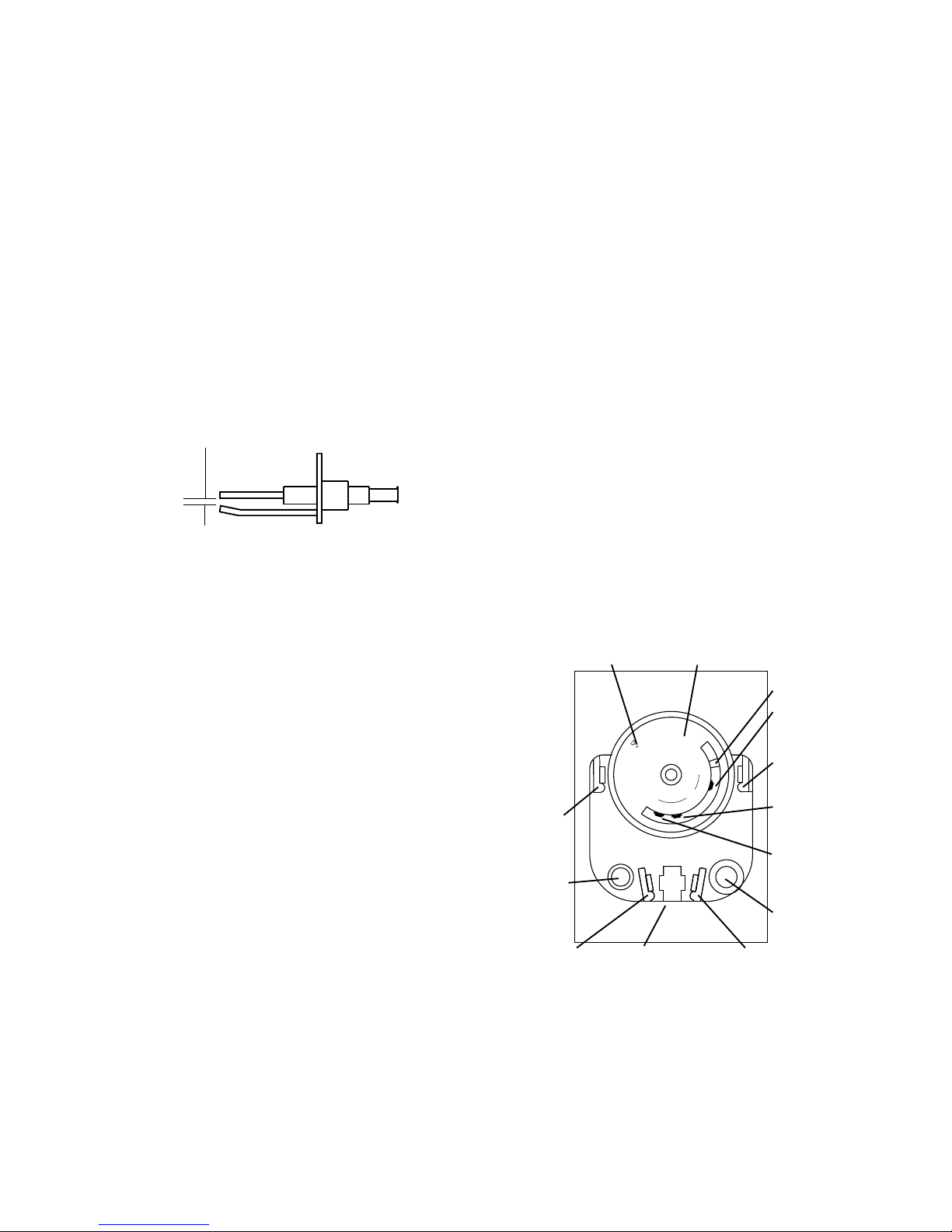
Fig 9 Ignition Electrode Spark Gap
7.4 Heat Exchanger
Whilst the main burner assembly is removed from the unit check
that the primary sections that the burners fire into are clean.
7.5 Main Fan Assembly
7.5.1 NVx/F & /C Models
1. Inspect the fan blades for any damage or excessive build up
of deposits that could give rise to an imbalance. Remove the
assembly for cleaning as follows.
2. Slacken the cable gland on the heater casing through which
the fan electrical cable passes.
3. Disconnect the fan leads from the electrical terminals.
4. Withdraw cable through entry grommet.
5. Remove the fan and motor assembly complete by removing
the hexagon headed screws that secure the fan to the rear panel.
6. Reassemble in reverse order.
7.5.2 Centrifugal Fan/Silencer Section
1. Remove section side panel(s) and inspect the fan blades for
any damage or excessive build up of deposits that could give
rise to an imbalance. Remove the assembly for cleaning as
follows.
2. Slacken the cable gland on the casing through which the fan
electrical cable passes.
3. Disconnect the fan leads from the electrical terminals in the
contactor enclosure.
4. Withdraw cable through entry grommet.
5. Remove the complete fan assembly by removing the fixings
securing the fan to the base rails.
6. Reassemble in reverse order.
7.6 Replacement of Faulty Components
7.6.1 Multifunctional Control
1. If there is movement available on the incoming gas pipe work
e.g. a flexible connection has been used go to step 2 otherwise
remove the burner assembly as previously described in Section
7.2
13
2. Remove the electrical plug connections from the top of the
multifunctional control.
3. Release the flanged connections at the inlet and outlet of the
multifunctional control and remove the multifunctional control.
4. Reconnect the new valve in the reverse order to that above
ensuring that the valve is correctly orientated. Renew the sealing
'O' rings if necessary.
7.6.2 Burners
1. Remove the burner assembly as described in Section 7.2.
2. Remove the end plates of the burner assembly and the central
burner support plate.
3. Exchange burners as required and reassemble components
in reverse order.
4. Re-commission the appliance as described in Section 6.
7.6.3 Electrode Assemblies
1. Disconnect the electrode leads from the DMN control box
as appropriate.
2. Remove the screw securing the electrode assembly to the
burner assembly side plate and withdraw the assembly.
3. Fit replacement and reassemble in reverse order. Check that
the spark gap is 2.5mm (See Fig. 8) and the rectification electrode
is 10 - 12mm forward of the burner.
7.6.4 Fan/Limit Thermostat
Thermostat settings: Fan Off Fan On Limit
NVx 10 - 140 30°C 50° 100
1. Release the screw securing the thermostat casing to the body,
squeeze the casing sides inward and pull casing forward.
2. Remove the electrical connections from the thermostat.
2.5mm
3. Remove the screws securing the thermostat to the bulkhead
and withdraw.
4. Fit replacement thermostat in reverse order.
Important: In this application the brass link is removed.
Note: NVx 10 to NVx 75 units have one fan/limit thermostat
whereas NVx 90 to NVx 140 units have two. The second
thermostat is at the opposite end of the heater to the
burner/controls end. The fan circuits are wired in parallel (either
thermostat will turn on the fan) and the limit thermostats are
wired in series (either thermostat will shut down the burner)
Fig 10 Thermostat Fan / Limit - Honeywell L4064N
CAUTION
DO NOT ROT ATE - HOLD
DIAL WHEN SETTING POINTERS
2
0
4
0
6
0
8
0
1
0
0
1
2
0
F
A
N
L
I
M
I
T
O
F
F
O
N
O
F
F
C
°
Limit Set point
Adjustment
Fan Circuit
OUT
Limit Circuit
OUT
Limit Reset
Fan ON
Override
Set Point Dial
Brass Link Location
Mechanical Limiter
Release Point
Mechanical limiter
Fan OFF Set point
Adjustment
Limit Circuit
IN
Fan Circuit
IN
Fan ON Set point
Adjustment
Page 18

14
7.6.5 Exhaust Fan
1. Remove the four screws securing the flue outlet socket.
2. Disconnect the fan electrical connections from the main
terminal strip
3. Remove the screws securing the fan mounting box to the
exhaust header plate.
4. Remove fan assembly.
5. If needed transfer the fan mounting box to the replacement
fan.
6. Fit replacement exhaust fan, using new gaskets and silicon
sealant as necessary, and reassemble in reverse order.
7.6.6 Air Pressure Switch
1. Remove the two screws securing the cover and remove cover.
2. Disconnect electrical connections.
3. Pull off the sensing tube from the air pressure switch.
4. Note the setting of the old pressure switch.
5. Remove the screws fixing the air pressure switch and remove
switch.
6. Fit replacement in reverse order refitting the sensing tube to
the negative (- or L) tapping on the pressure switch. Adjust
setting to that of the old pressure switch.
7.6.7 Control Box
1. Unplug all the electrical connections.
2. Remove the four screws that secure the control box in place.
3. Fit replacement in reverse order.
7.6.8 Centrifugal Fan/Motor
1. Disconnect the electrical connections to the centrifugal fan
section.
2. Remove the side panels of the section for access to the fan
and motor.
3. Fit replacements as appropriate and reassemble in reverse
order.
Note: If a 3ph motor is being replaced ensure that the direction
of rotation is correct. If it is not interchange any two of the three
phases connected to the motor.
Page 19
4A
FUSE
J5
J6
JT2
JT1
BRAHMA
CODE 3756400
Type DMN3 2
C
RED
°C °C
L
1
4
5
6
2
D
NC
NO
C
E
F
Br 0.5
Blu 0.5
O
Br 0.5
Blu 0.5
Blu 0.5Br 0.5
Or 0.5
FAN
LIMIT
Or 0.5
Yel 0.5
Wh 0.5
N
Blk 0.5
Br 0.5
Blk 0.5
Grey 0.5
Wh 0.5
Blu 0.5
Blk 0.5
Wh 0.5
Blu 0.5
J K
Or 0.5
Yel 0.5
Or 0.5
3
Live
Neutral
G
B
A
15 17 18
19
7
7
1413
1 2 3 4 5 6 7
8
9
10
11
12
16 17 18 19 13 14 15
9
10
12
11
GREEN
8
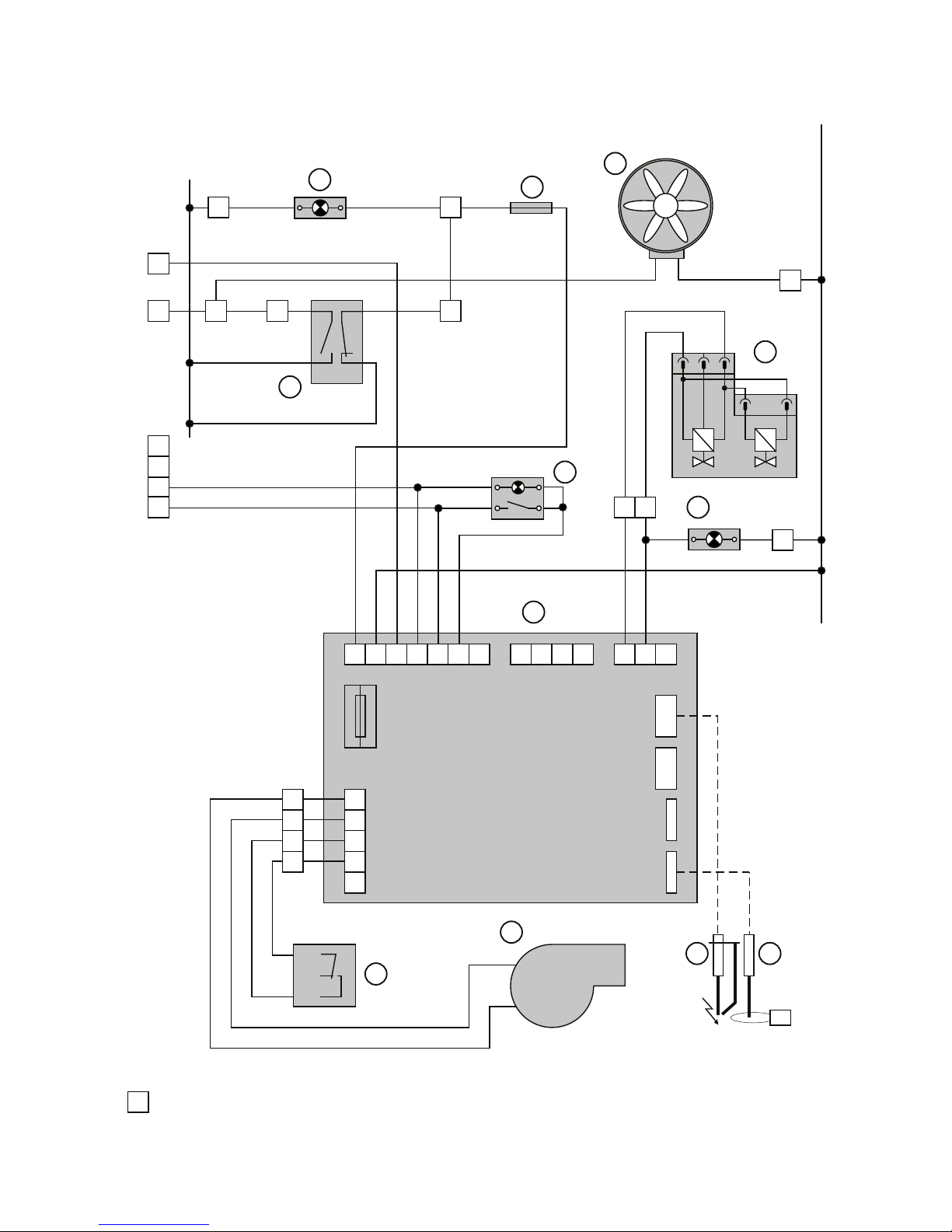
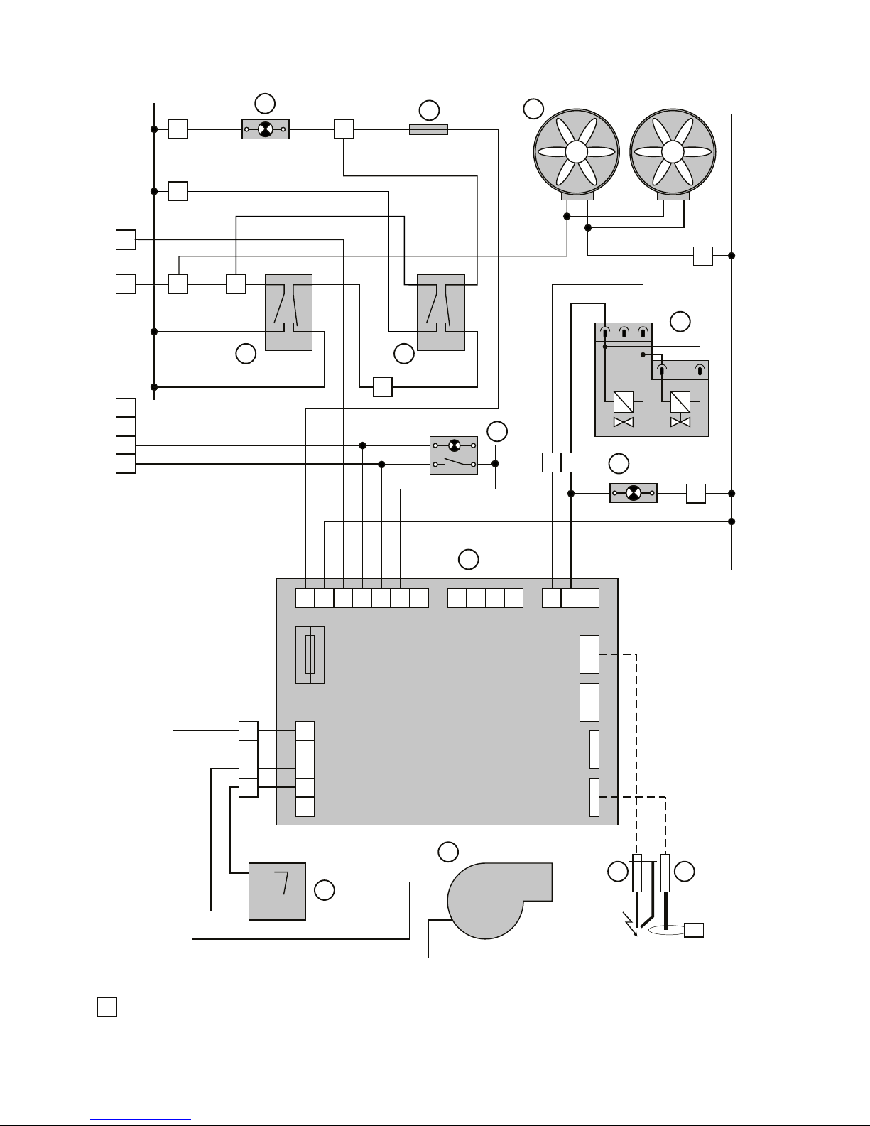
8. Functional Flow Diagram
8.1 NVx10 - 75 Basic Unit
A. Brahma Control DMN32
B. Honeywell Fan/Limit Thermostat
C. Red Neon Indicator
D. Air Pressure Switch LGW3 A2
E. Main Gas Valve
F. Exhaust / Combustion Fan
G. Main Fan
J. Ignition Electrode
K. Rectication Probe
L. Fuse 3.15A
N. Internal Lockout Reset Button
O. Green Neon Indicator
Terminals
1 - Heat demand (230V input)
2 - Main Fan only operation (230V input)
3 - For use on High/Lo & Modulating Units
4 - For use on Modulating Units
5 - Lockout Indication (230V output)
6 - Lockout Reset (Switched to Neutral)
Notes:
Represent NVx Terminalsa)
b) NVx terminals 3 & 4 are used in High/Lo and Modulating units
c) Earth connections are not shown
1
3.15A
FUSE
15
Page 20
A. Brahma Control DMN32
B. Honeywell Fan/Limit Thermostat
C. Red Neon Indicator
D. Air Pressure Switch LGW3 A2
E. Main Gas Valve
F. Exhaust / Combustion Fan
G. Main Fans
J. Ignition Electrode
K. Rectication Probe
L. Fuse 3.15A
N. Internal Lockout Reset Button
O. Green Neon Indicator
4A
FUSE
J5
J6
JT2
JT1
BRAHMA
CODE 3756400
Type DMN3 2
C
RED
°C °C
L
1
4
5
6
2
D
NC
NO
C
E
F
Br 0.5
Blu 0.5
Br 0.5
Blu 0.5
Blu 0.5Br 0.5
Grey 0.5
Blk 0.5
FAN
LIMIT
Or 0.5
Yel 0.5
Wh 0.5
N
Blk 0.5 Or 0.5Grey 0.5
Yel 0.5
Yel 0.5
Br 0.5
Br 0.5
Blk 0.5
Wh 0.5
Blu 0.5
Blk 0.5
Wh 0.5
Blu 0.5
J K
Or 0.5
3
Live
Neutral
G
B
A
O
15 17
7
7
1413
1 2 3 4 5 6 7
8
9
10
11
12
16 17 18 19 13 14 15
9
10
12
11
GREEN
8
8.2 NVx90 - 140 Basic Unit
Terminals
1 - Heat demand (230V input)
2 - Main Fan only operation (230V input)
3 - For use on High/Lo & Modulating Units
4 - For use on Modulating Units
5 - Lockout Indication (230V output)
6 - Lockout Reset (Switched to Neutral)
Notes:
Represent NVx Terminalsa)
b) NVx terminals 3 & 4 are used in High/Lo and Modulating units
c) Earth connections are not shown
1
3.15A
FUSE
B
°C °C
FAN
LIMIT
19
18
16
16
Page 21
17
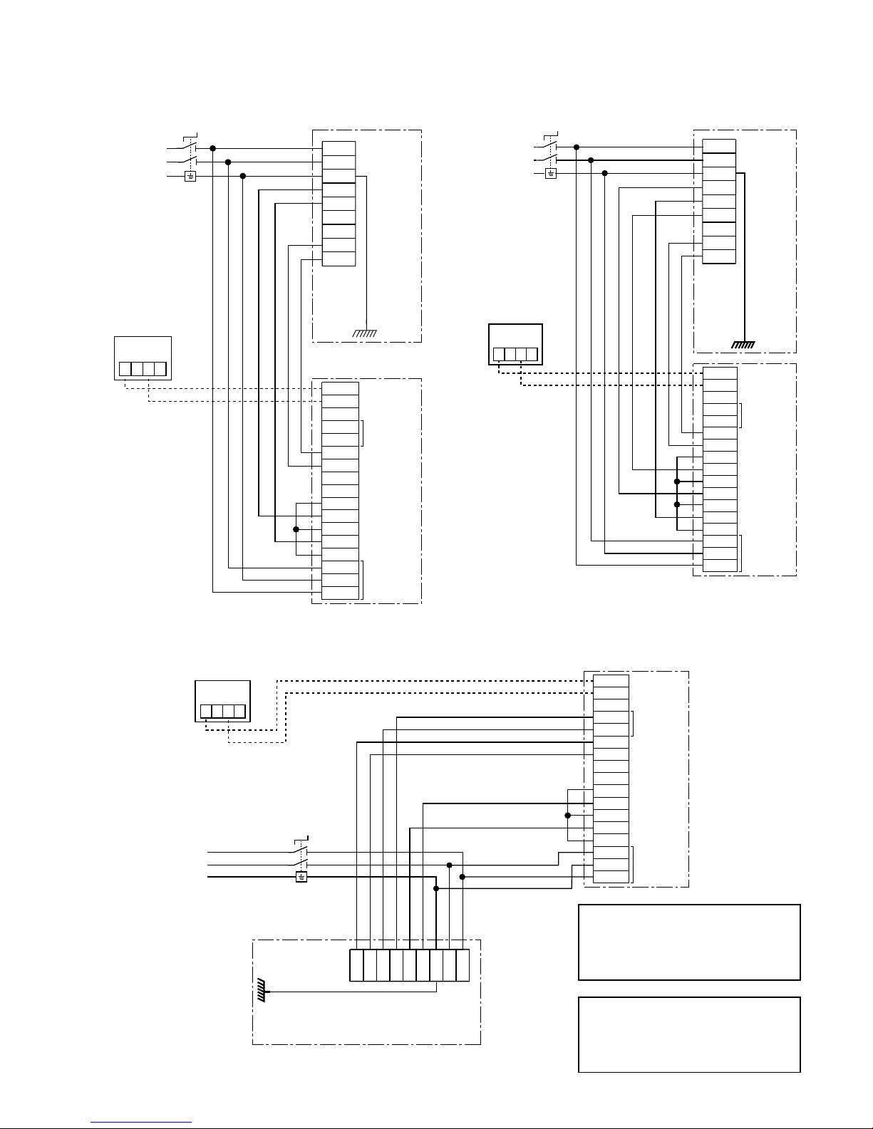
9. Connections to External Controls
Note:
To comply with ECA requirements and to achieve maximum system eciency it is recommended that NVx units are controlled by an MC200 Fuel Saver unit. Simple room
thermostat and room thermostat/time clock control systems will not provide optimum system eciency and fuel savings.
NEUTRAL
LIVE
EARTH
NVx HEATER (ON/OFF)
1
L
N
E
2
3
4
5
6
Note: MC200
internal sensor
is removed
Remote Sensor
(optional)
T1 3 T2 1
MC200 FUEL SAVER
N
RESET
IN 2
COM
SEN 1
0-10V+
0-10V-
Lockout
Fan In
Heat Hi In
Heat Hi Out
Heat Lo In
Heat Lo Out
E
L
Fan Out
L Out
SUPPLY IN Mod Out
1
2
3
4
5
6
7
8
9
11
12
14
17
16
15
13
10
Hi/Lo NVxOn/O NVx
Modulating NVx
NVx HEATER (Hi/Lo)
Remote Sensor
(optional)
T1 3 T2 1
MC200 FUEL SAVER
N
RESET
IN 2
COM
SEN 1
0-10V+
0-10V-
Lockout
Fan In
Heat Hi In
Heat Hi Out
Heat Lo In
Heat Lo Out
E
L
Fan Out
L Out
SUPPLY IN Mod Out
1
2
3
4
5
6
7
8
9
11
12
14
17
16
15
13
10
NEUTRAL
LIVE
EARTH
Note: The NVx Heater and MC200
may be fed by separate electrical
supplies providing both supplies are
the same phase.
Warning: If external controls are
not isolated 230V may be present at
heater terminals even when the
heater is isolated.
MC200 FUEL SAVER
N
RESET
IN 2
COM
SEN 1
0-10V+
0-10V-
Lockout
Fan In
Heat Hi In
Heat Hi Out
Heat Lo In
Heat Lo Out
E
L
Fan Out
L Out
SUPPLY IN Mod Out
1
2
3
4
5
6
7
8
9
11
12
14
17
16
15
13
10
Remote Sensor
(optional)
T1 3 T2 1
NEUTRAL
LIVE
EARTH
NVx HEATER (Modulating)
1
L
N
E
2
3
4
5
6
1
L
N
E
2
3
4
5
6
Note: MC200
internal sensor
is removed
Note: MC200
internal sensor
is removed
Page 22
18
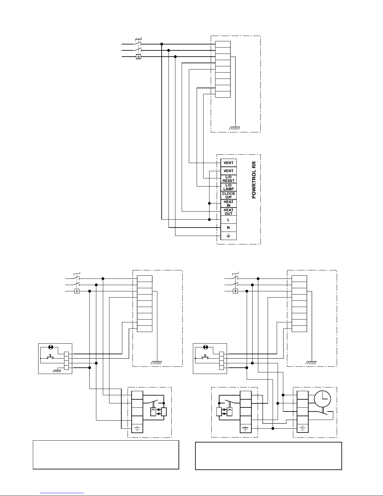
Note: The NVx Heater, Powrtrol, time clock or room
thermostat may be fed by separate electrical supplies
providing both supplies are the same phase.
Warning: If external controls are not isolated 230V
may be present at heater terminals even when the
heater is isolated.
ON/OFF NVx
TIME
SWITCH
ROOM
STAT
RF
Lockout Indicator
Push Button
Reset
L/O
R/S
N
E
230V
L
N
L
in
L
out
N
L
out
L
in
ROOM
STAT
RF
Lockout Indicator
Push Button
Reset
L/O
R/S
N
E
230V
N
L
out
L
in
NEUTRAL
LIVE
EARTH
NVx HEATER (ON/OFF)
1
L
N
E
2
3
4
5
6
NEUTRAL
LIVE
EARTH
NVx HEATER (ON/OFF)
1
L
N
E
2
3
4
5
6
NEUTRAL
LIVE
EARTH
NVx HEATER (ON/OFF)
1
L
N
E
2
3
4
5
6
Page 23
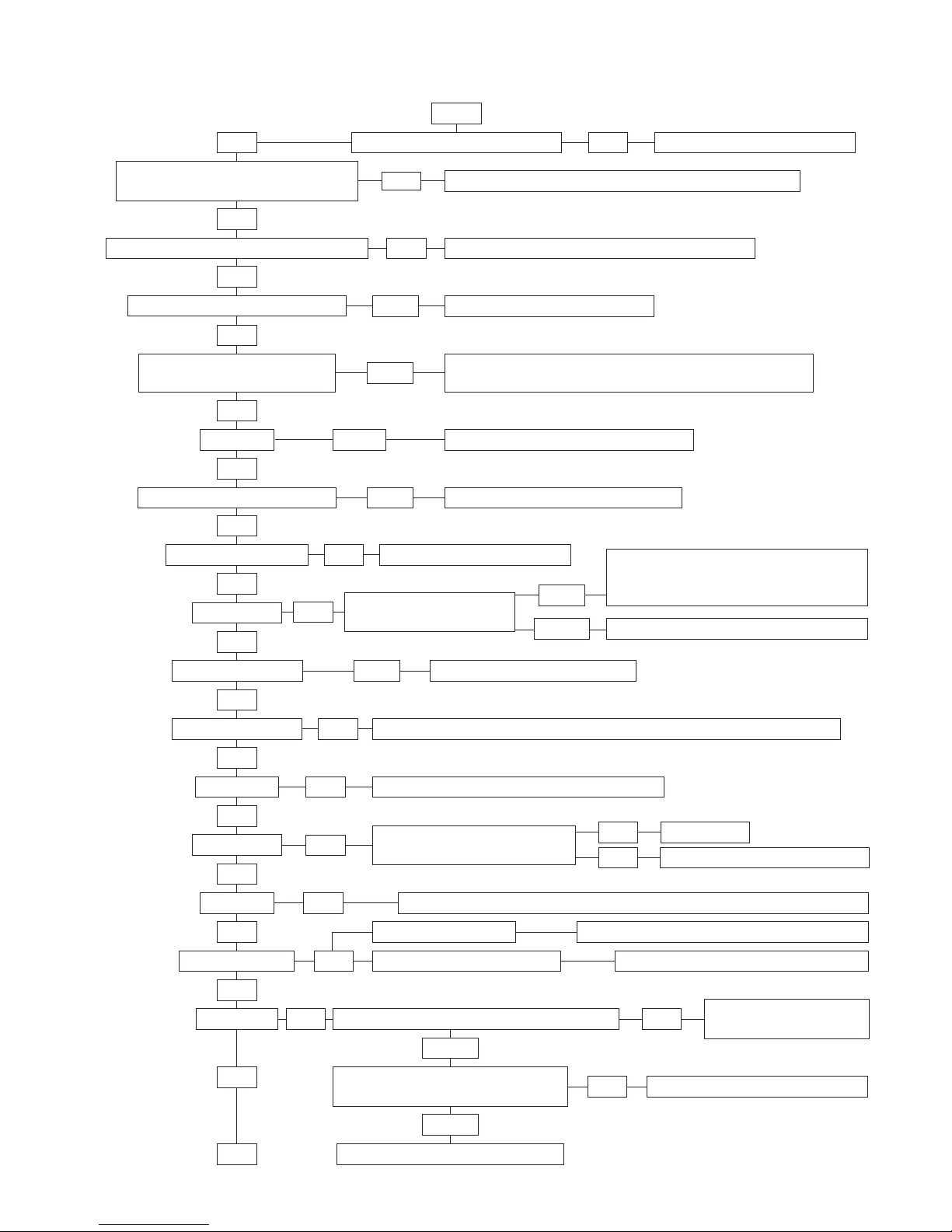
9. Fault Finding Flow Chart
19
Note: APS = Air Pressure Switch
Check Fuse ‘L’
Gas & Electrical supplies present at heater?
No
Turn supplies on, Check fuses/connections
230V Between 1 & 2 on Brahma control?
Limit thermostat tripped (red lamp on front panel on)?
Check fuse on Brahma control
Press red reset button on fan/limit thermostat (in controls section)
Yes
No
Unit at lockout (lockout lamp on low level controls
and on internal control panel alight)?
No
Check for 230V at upper terminal on
limit side of fan/limit thermostat
Yes
Replace (3.15A), ascertain cause of failure and rectify
Replace (4A), ascertain cause and rectify
Failed
Failed
Check for faulty connection. Replace as necessary.
Yes
START
OK
OK
Yes
Yes
No
Check APS sensing tube. Check negative pressure developed by exhaust fan. Adjust APS set point. Change APS
Yes
Yes
Ignition sparks?
Check/replace ignition probe/lead. Faulty Brahma control box
Yes
Burners light?
Check ignition electrode position. Is gas pipe work purged of air? Check gas pressures. Replace gas valve
Check rectication probe/lead. Faulty Brahma Control
4 more ignition attempts then lock out.
Exhaust fan continues to run APS has lost C. to N.O. continuity, slightly reduce APS set point.
Check for 230V between terminals 7 & 15 of the terminal strip
Absent
Replace motor, capacitor or fan/motor assembly
Check connections, overloads etc as applicable
Absent
Finish
Burners remain alight?
Check for 230V between terminals
12 & 11 of the terminal strip
Check connections, Faulty Brahma Control
Yes
230V at APS Terminal C ?
Present
230V at APS Terminal N.O ?
No
Check for 230V between terminals 13 & 14
of the terminal strip
Check connections, Faulty Brahma Control
No
Faulty Gas Valve
Yes
No
No
No
No
Main fan runs?
Main fan running - wait for unit temperature to reduce - push
red thermostat reset button. If it will not reset when cold - change thermostat
Check for 230V at terminal 1 of terminal strip
Absent
Absent
Absent
Absent
Absent
External control circuit not calling for heat
Press lockout reset button on low level controls or on internal control panel
Continuity between APS C and NO connections - check
for reason, adjust APS setting or change APS. Faulty
Brahma control or connections.
Check connections, Faulty exhaust fan and/or capacitor
Yes
Yes
Yes
Exhaust fan runs?
No
Yes
Yes
Gas valve opens?
Depending on fan /motor type - Check for 230V at
the main fan motor
Check connections. Fan/limit
thermostat faulty - check/replace
Present
Present
Page 24
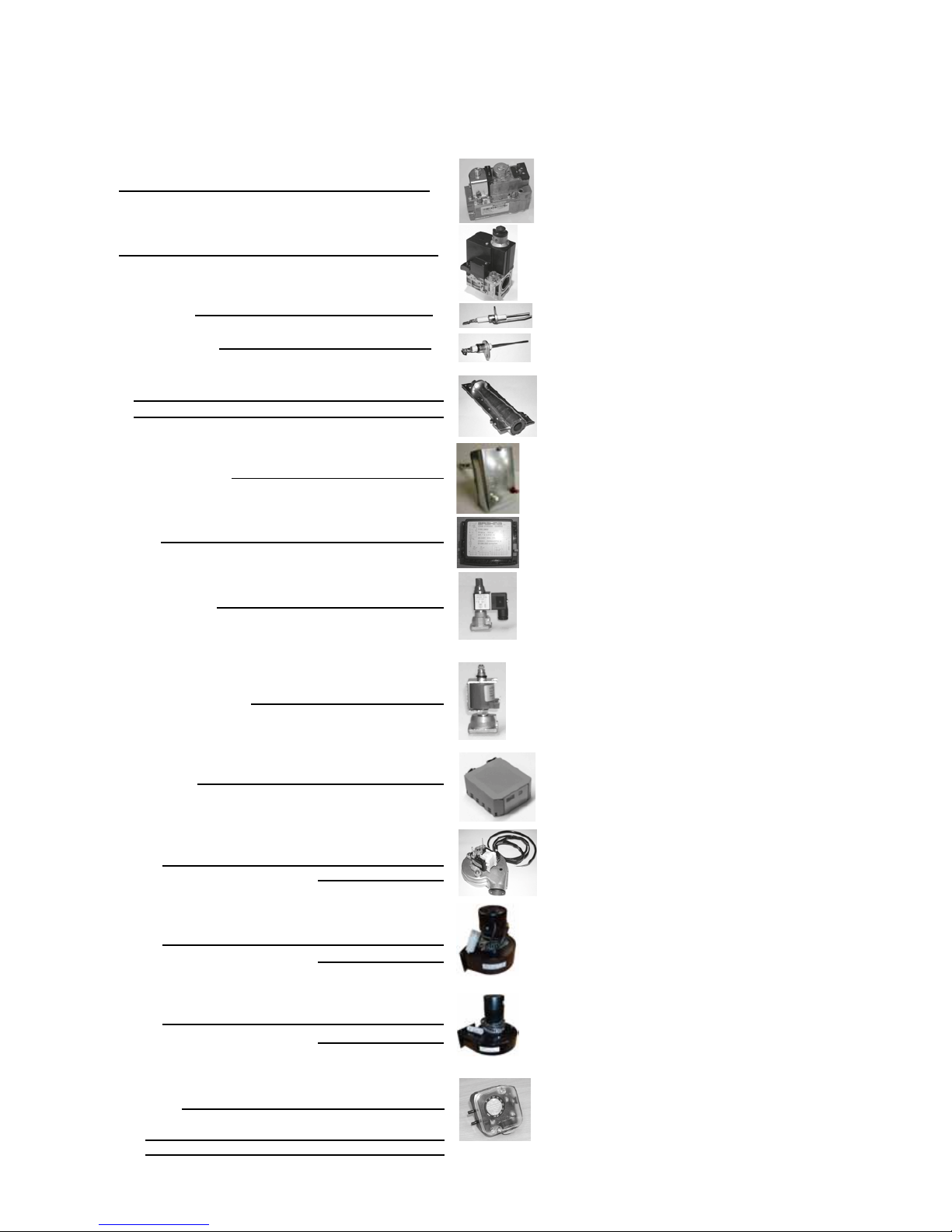
ITEM USAGE PART #
MFC 10-90 145035204
MFC 120/140 141378715
Ignition Electrode 10-75 142423002
Ignition Electrode 90-140 142423004
Rectification Electrode All 142423003
Burner 10-75 142400240
Burner 90-140 142400241
Fan & Limit Thermostat All 143000303
Control Box All 145030844
Hi/Lo Governor Head 10-140 -/HL 142466402
Modulating Governor Head 10-140 -/MOD 142466403
Modulating Driver 10-140 -/MOD 142400305
Exhaust Fan 10-50 140210496
As an assembly c/w mounting brackets 10-50 NVX1050EXH
Exhaust Fan 60/75 140201505
As an assembly c/w mounting brackets 60/75 NVX6075EXH
Exhaust Fan 90-140 140201506
As an assembly c/w mounting brackets 90-140 NVX90140EXH
Pressure Switch All 146522174
Contactor 120-140, All -/C 143000600
Contactor 60-90, All -/C 143000601
10. Short List of Parts
Only originally specied parts may be tted as service replacements and all items are available from the Powrmatic Ltd Spares Department. Please refer to Powrmatic Ltd
for any parts not shown in the listing. Powrmatic Ltd must also be consulted before parts other than those specied or recommended in the servicing instructions are
replaced.
20
Page 25
Every effort is made to ensure accuracy at time of going to press. However as part of our policy of continual product improvement, we reserve the right to alter specifications without prior notice.
HEATING DIVISION
Hort Bridge
Ilminster, Somerset TA19 9PS
Tel: 01460 53535 Fax: 01460 52341
BSI Registered Firm
FM 414
Ind. & Comm. Air Heaters;
Air Moving Equipment;
Flues & Chimneys; Natural
Smoke & Heat Ventilators;
Powered Supply & Extract
Fans & Systems.
ISO 9001
ITEM USAGE PART #
Main Air Fan - Axial 10 140232001
Main Air Fan - Axial 15 140232002
Main Air Fan - Axial 20 140232003
Main Air Fan - Axial 25/30 140232004
Main Air Fan - Axial 35/40 140232005
Main Air Fan - Axial 50/90 140232006
Main Air Fan - Axial 60/75/120/140 140232007
 Loading...