

Powrmatic NVx10, NVx25, NVx15, NVx20, NVx30 User, Installation And Servicing Instructions
...
Users, Installation and Servicing
Instructions
WARNING: THIS APPLIANCE MUST BE EARTHED
IMPORTANT: Reset from Lockout is by a switched Neutral
CE
NVx Range Users, Installation & Servicing Instructions Issue 1.9 March 2012
The NVx Range
(Brahma Control)
Dear Customer
This is to certify that this heater is guaranteed for two years parts and one year
labour from the date of original commissioning. The heater must be
commissioned within 4 weeks of installation.
The heat exchanger, where fitted, is guaranteed (parts only) for a further eight
years, chargeable on a sliding scale basis, price relative to age.
To make a claim
In the first instance you must contact your appliance supplier, or installer and
provide:-
1. The appliance type and serial number.
2. The original commissioning documentation.
3. As much detail as possible on the fault.
Your supplier, or installer, will then contact Powrmatic to make a guarantee
claim on your behalf.
Conditions of Guarantee
1. The heater must have been installed by a competent recognised installer, and
in accordance with the manufacturers instructions, building regulations and
local regulations.
2. The heater has been professionally commissioned, within 4 weeks of
installation, and a copy of the Commissioning Sheet returned to Powrmatic.
3. The heater has been maintained on a yearly basis by a competent servicing
company.
4. The heater has been used in accordance with the manufacturers instructions.
5. The correct specification fuel has been used
6. No unauthorised repairs or modifications have been made.
7. Powrmatic ‘General Conditions of Sale’ have been observed.
8. Except for the obligation of Powrmatic Ltd to perform warranty repairs during
the guarantee period, Powrmatic will not be liable in respect of any claim for
direct or indirect consequential losses, including loss of profits or increased
costs arising from loss of use of the heater, or any event arising there from.
Exclusions
1. Gaskets and fan belts are not included in the guarantee
Important: This certificate must
be kept with the appliance
Certificate of Guarantee
Powrmatic Ltd, Hort Bridge, Ilminster, Somerset, TA19 9PS
tel: 01460 53535 fax: 01460 52341
web: www.powrmatic.co.uk e-mail: service@powrmatic.co.uk
Installed
Date: ___________ Signed______________________________________ Installer
Commissioned
Date: ___________ Signed________________________ Commissioning Engineer
Failure to provide a copy of the Commissioning Sheet invalidates the heater warranty

1. Checks before lighting the Air Heater
The following preliminary checks should be made before lighting
the heater(s)
a) Ensure that the ELECTRICAL supply to the heater is
switched OFF.
b) Check that all warm air delivery outlets are open.
c) Check that the thermostat is set at MAX.
d) Check that the clock control is set to an ON period.
e) Check that any other controls are calling for heat.
2. Lighting the Air Heater
NOTE:
On initial lighting of the heater(s), it may take some time to
purge the internal pipe work of air. If it is not possible to light
the heater after several attempts contact the local service
company.
1. Switch on the electrical supply at the isolator and the start up
sequence will commence.
Note: Check that the red overheat indicator on the front of the
unit is not alight. If it is refer to Section 4.4
After a short delay the burners will light and the green ‘ON’
indicator on the front of the heater will be illuminated.
2. If the burners fail to light the control box will automatically
restart the ignition sequence. If after 5 attempts at ignition the
burners have still failed to light the control box will go to lockout
and the lockout light on the low level remote reset (or MC200
or Powrtrol RR if fitted) will be illuminated. To restart the
ignition sequence depress the reset button on the low level reset
for about 1-2 seconds.
If the heater will not light after two or three attempts shut down
the heater and contact a service engineer.
3. To Shut Down the Air Heater
3.1 For Short Periods: Turn the room thermostat to the OFF
or lowest setting.
3.2 For Long Periods: Complete step 3.1 above. Wait for 5
minutes and then turn OFF the
electrical supply at the isolator.
4. Description of Operation
Important: All heaters must be controlled by the fitted external
controls and not by use of the main switch in the electrical
supply to the heater.
4.1 Standard Units
The ignition sequence will commence each time that the external
controls e.g. Time clock, room thermostat etc. call for heat. The
internal exhaust fan will run and when sufficient combustion
airflow is proved by the air pressure switch the ignition spark
will be generated, the main gas valves opened and the burners
lit. The green ‘ON’ indicator will be illuminated. The heater fan
will automatically start approximately 2 minutes after the burners
light. When the external controls are satisfied the burners will
be turned off and approximately 2 - 3 minutes later the heater
fan will be automatically stopped.
4.2 High / Lo & Modulating Units
When the burners are alight the heat output will be controlled
either to high fire or low fire or, in the case of modulating units,
to any point between high and low fire; depending on the
requirements of the space being heated and the external controls
fitted.
4.3 Summer / Winter Modes
Certain types of external controls will provide for two modes
of operation i.e.
Summer: The heater fan alone will run at the dictate of the
external controls to provide air movement.
Winter: The heater will operate normally.
4.4 Overheat Thermostat
This operates if high temperatures within the heater are detected,
the burners are turned off and a red indicator light on the front
panel is illuminated. NVx10 - 75 units have the thermostat
located inside the controls section. NVx90 - 140 units have an
additional thermostat on the side of the unit at the opposite end
to the controls (either thermostat can go to limit and shut off
the burners). The fault condition must be identified and rectified
and the thermostat manually reset.
Isolate the electrical supply to the heater and open the controls
section door. Push in the red button on the fan/limit thermostat
(located towards the top of the compartment) to reset. On NVx90
- 140 units also reset the second limit thermostat.
Note: The thermostat can only be reset once the unit has cooled
down.
Unless the cause of the fault condition is readily obvious, for
example a power cut whilst the heater was operating, a service
engineer should be contacted.
5. Maintenance
To maintain efficient, reliable and safe operation of the heater
it must serviced by a qualified person at least annually and
preferably at the end of the heating season.
6. IMPORTANT
Free access must be maintained to and around the heater for
servicing purposes and the air supply to the heater must not be
restricted in any way. Combustible materials must not be stored
adjacent to the heater.
If at any time a gas leak is suspected turn OFF the gas supply
- DO NOT USE A NAKED FLAME - and contact the local gas
undertaking immediately.
All Powrmatic heaters use gas and electricity to power them,
they may also contain moving parts such as pulleys and belts.
It would be hazardous to tamper with or attempt to service unless
you are a competent person in the field of Gas and Electrical
work.
If you have any safety questions reference the servicing and
installation of any of our heaters please do not hesitate to contact
our head office for expert advice. Your safety is paramount to us.
Gas Safety (Installation & Use) (Amendment) Regulations
It is law that all gas appliances are installed, adjusted and, if
necessary, converted by qualified persons* in accordance with
the current issue of the above regulations. Failure to install
appliances correctly can lead to prosecution. It is in your own
interests and that of safety to ensure that the law is complied
with.
* An approved class of person listed on the gas register.
Users Instructions

CONTENTS
Section Title Page
1.
Introduction 1
2. Technical Data 2
3. General Requirements 6
4. Installation 7
5. Air Distribution System 10
6. Commissioning & Testing 10
7. Servicing 12
8. Functional Flow Diagram 15
9. Connections to External Controls 17
10. Fault Finding Flow Chart 19
11. Short List of Parts 20
Tables Title Page
1. Dimensions 3
2. Specifications 3
3. Electrical Loadings 1ph 4
3.1 Injector Sizes & Burner Pressures
Natural Gas - Group H - G20 5
3.2 Injector Sizes & Burner Pressures
Propane - G31 5
Figure Title Page
1a. Exhaust only system - horizontal 8
1b. Exhaust only system - vertical 8
2a. Individual system - horizontal 9
2b. Individual system - vertical 9
3. General Controls Layout 10
4. Governor adjustment (Honeywell VR425A) 11
5. Governor adjustment (Honeywell VR4605A) 11
6. High/Lo Regulator 11
7. Modulating Regulator 12
8. Flame Current Measurement 12
9. Ignition Electrode Spark Gap 13
10. Thermostat Fan / Limit - Honeywell L4064N 13
Installation & Servicing Instructions

1. INTRODUCTION
The NVx range are highly efficient gas fired, fanned circulation
air heaters that cover heat outputs of 10kW to 140kW, have a
closed combustion circuit and are supplied complete with a flue
system. They are certified for use on Natural Gas, Group H G20, and Propane - G31 only.
Appliance Categories are Cat II2H3P (GB, IE).
The heaters are designed to be suspended from suitable roof
points or alternatively to be mounted on purpose designed
brackets and are intended primarily for heating commercial or
industrial premises.
NVx heaters feature a closed combustion circuit and have an
internal exhaust fan, mounted downstream of the heat exchanger,
to evacuate the products of combustion and draw in air for
combustion. The air heater must be connected to the flue system
that is provided by Powrmatic Ltd.
They may be used where the atmosphere inside the premises
could be contaminated e.g. Dust, oil mist etc. but the heaters
are not airtight and therefore may not be used in areas classified
as hazardous as defined in BS 5345: Part 2 or areas subjected
to significant negative pressures due to extract systems.
NVx/F heaters have an axial fan assembly fitted at the rear to
circulate the air being heated through the folded tube heat
exchanger. NVx/C units are supplied with a centrifugal fan and
NVx/D units for use with ducted systems where the air moving
fan is by others or a centrifugal fan section is used adjacent to
or remote from the heater. NVx/DH units are for use in air
handling units and NVx/EA units are for siting externally.
Heaters are fitted as standard with inshot burners, a fully
automatic control for ignition, flame sensing, gas supply control
and safety functions, an internal exhaust fan, main air fan (/F
and /C models), and fan/limit thermostat.
Options include High/Low or Modulating burner controls, inlet
duct connection, outlet duct connection, 45° head, 90° outlet
bend, vertical/horizontal outlet louvre assembly and a full range
of modular duct components.
IMPORTANT
Service and Maintenance Engineers shall ensure that replacement
items are fitted, adjusted and set in accordance with the data
and detail set out in these instructions. If in doubt consult
Powrmatic Technical Department.
Gas Safety (Installation & Use) Regulations 1998
It is law that all gas appliances are installed, adjusted and, if
necessary, converted by qualified persons* in accordance with
the current issue of the above regulations. Failure to install
appliances correctly can lead to prosecution. It is in your own
interests and that of safety to ensure that the law is complied
with.
* An approved class of person listed on the gas register.
1
2. TECHNICAL DATA
2
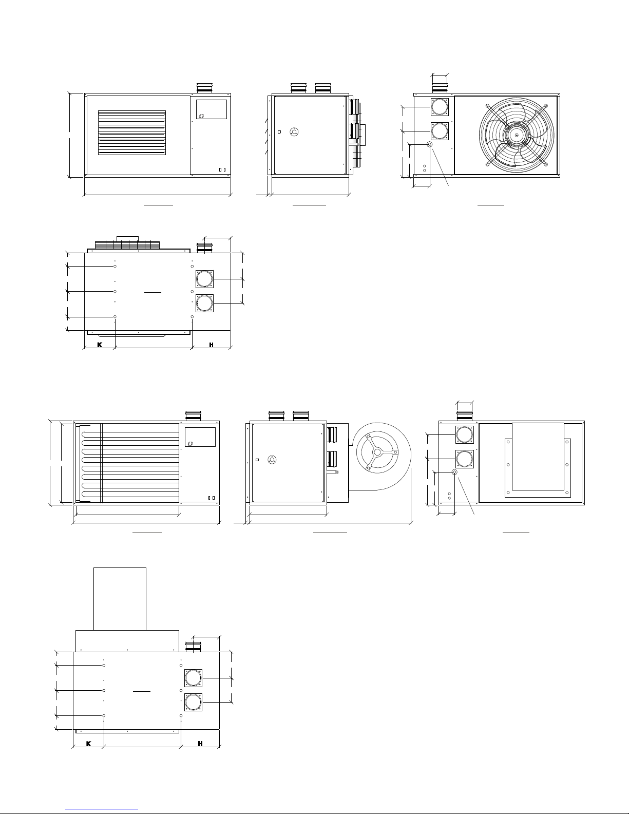
R/H SIDE VIEW
A B
REAR VIEW
PLAN
FRONT VIEW
GAS ENTRY POINT
N
P
F
G
E
G
M
H
J CTRS
K
228 CTRS
228 CTRS
122
122
C
ø D
35
NOTE: For dimensioning purposes both top and rear
flue and combustion air connections are shown
R/H SIDE VIEW
A
REAR VIEW
PLAN
FRONT VIEW
N
P
F
G
E
G
M
H
J CTRS
K
228 CTRS
228 CTRS
122
122
C
ø D
35
NOTE: For dimensioning purposes both top and rear
flue and combustion air connections are shown
L
B
T
S
NVx
POWRMATIC
NVx
POWRMATIC
GAS ENTRY POINT
NOTE: For dimensioning purposes both top and rear
flue and combustion air connections are shown
33.733.7
T
S
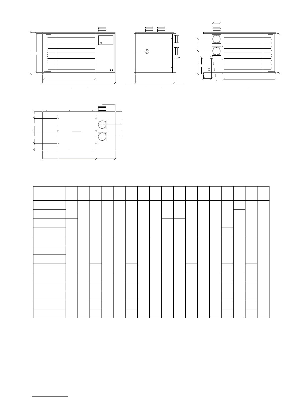
R/H SIDE VIEW
A
S
REAR VIEW
PLAN
FRONT VIEW
N
P
F
G
E
G
M
H
J CTRS
K
B
228 CTRS
228 CTRS
122
122
C T
ø D
NVx
POWRMATIC
GAS ENTRY POINT
Table 1. Dimensions
3
NVx
15
NVx
25
NVx
30
NVx
50
NVx
60
NVx
75
NVx
90
NVx
120
NVx
140
NVx
35
Model
NVx10
B
700
A
1000
1325
2325
785
C
540
760
912
912
700
760
831
975
422
637
932
1932
492
712
864
864
652
712
783
927
ØD E
233.5
24880
100
130
F
492
644
416
568
321
487
631
308
G
142
220
120
H
347
317
J
450
700
850
250
M
236
246
206
216
L
524
752
904
752
904
639
804
969
K
218
232.5
278
NVx
20
NVx
40
N
114
145
88
P
¾'’
194
225.5
297
374
374
260
326
398
297
S T
Gas
inlet
Ø

Table 3
Electrical Loadings 1ph
NVx
90
NVx
120
7.81 4.22
9.57 5.13
NVx
140
9.64 4.98
/F Models /C Models
MODEL
PLATE
AMPS
(A)
START
AMPS
(A)
RUN
AMPS
(A)
FUSE
RATING
(A)
NVx
10
2
NVx
15
0.18 0.34 0.16
870
2.8 4.2 2.10
1.39 0.51 4.0 8.1 2.60
NVx
20
0.38 0.28 4.0 7.8 3.20
3
NVx
30
1.83 0.61 14.7 4.50
7
NVx
40
1.30
2.56
1.35 8.4
14.5 5.00
NVx
50
1.40 4.01 1.96 3 16.0 6.40
NVx
60
4.70 2.44
NVx
75
4.78 2.51
2 x 1.40
NOMINAL
MOTOR
R.P.M.
PLATE
AMPS
(A)
START
AMPS
(A)
RUN
AMPS
(A)
FUSE
RATING
(A)
NVx
25
1.89 0.62
0.54
0.89
2.50
2 x 2.50
0.31
7
5
NOMINAL
MOTOR
R.P.M.
4.0 8.2 2.90
28.4 11.6
25
900
1400
775
910
820
900
11.1
2 x 8.4
2 x 11.1
24.5 10.6
42.5 21.5
24.5 12.3
16
NVx
35
Note: 3ph Data is
supplied separately with
units ordered to this
specification.
14.0
39.8
5.30
25.2
5
Table 2 - Specifications
4
Note: /D data refers to Powrmatic supplied centrifugal/silencer duct section
MODEL
INPUT
(Nett)
OUTPUT
INPUT
(Nett)
OUTPUT
kg
kW kW m³/s m³/h Pa kW
NVx10
10.79 10.0 6.57 5.90 0.2601
NVx15
16.00 15.0 8.22 7.50 0.3902
NVx20
21.85 20.0 11.58 9.92 0.5203
NVx25
27.32 25.0 16.50 14.30 0.6503
NVx30
32.60 30.0 18.34 16.30 0.7804
NVx40
43.48 40.0 24.19 21.22 1.0405
NVx50
54.23 50.0 28.40 24.83 1.3006
N/A 0.040 53
140
0.250
91.5
N/A
0.120
59.5
145 0.370 106.5
N/A 0.070 69.5
177 0.370 120.5
N/A 0.180 74.5
143 0.370 126.5
N/A 0.180 96.0
250 1.100 166.5
N/A 0.300 108.0
236 1.100 168.5
N/A 0.440 123.0
205 1.100
183
F
D
F
D
F
D
F
D
F
D
F
D
F
D
HIGH FIRE LOW FIRE
AIR
VOLUME
MAXIMUM
DUCT
RESISTANCE
FAN
MOTOR
WEIGHT
NVx60
65.22 60.0 35.63 31.49 1.5608
N/A 0.550 138.5
250 1.50
213
D
F
F
D
F
D
D
F
NVx75
NVx90
NVx120
81.5 75.0
97.8 90.0
130.4 120.0
42.61 37.50
58.50 54.50
75.45 71.00
1.9510
2.3412
3.1215
N/A 0.550 158.0
260 1.50 234
N/A 2 x 0.440 204.0
200 2 x 1.10 343
N/A 2 x 0.550 260
284 2 x 1.50 363.5
D
F
NVx140
152.1 140.0 98.92 92.55 3.6418
N/A 2 x 0.550 260
285 2 x 1.50 424
NOISE
LEVEL
dB(A) @ 3m
N/A
N/A
N/A
N/A
N/A
N/A
N/A
N/A
N/A
N/A
N/A
N/A
46
54
52
53
54
58
61
62
62
66
67
67
NVx35
F
D
39.32 34.95 23.1 19.0 1.000
936
1405
1873
2341
2809
3746
4682
5619
7024
8428
11237
13110
3600
N/A 0.300 96.0
210 1.100 166.5
N/A
58
 Loading...