

Powrmatic NCA-G Series, NCA-G 200, NCA-G 300, NCA-G 100, NCA-G 150 Installation And Servicing Instructions
Page 1

The NCA-G Range
CE
Installation and Servicing
Instructions
WARNING: THIS APPLIANCE MUST BE EARTHED
£2.50 When supplied separately.
NCA-G Range Issue 4 Feb 1999
Page 2

CONTENTS
Section Title Page
1. Introduction 1
2. Technical Data 2
3. General Requirements 3
4. Installation 4
5. Air Distribution System 5
6. Commissioning & Testing 5
7. Servicing 6
8. Connections to Powrmatic
External Controls 7
9. Fault Finding 8
10. Short List of Parts 8
Tables Title Page
1. Dimensions 2
2. Performance Data 2
3.1 Burner Pressures - Natural Gas
Group H - G20 2
3.2 Burner Pressures - Propane - G31 2
4. Electrical Loadings 3
Figure Title Page
1. Gas Control Schematic NCA-G 100 - 300 6
2a. Gas Controls Layout NCA-G 100, 150 6
2b. Gas Controls Layout NCA-G 200, 300 6
3. Honeywell L4064N 7
Appendix Title Page
A Calculation Of Flue System Inside
Equivalent Resistance Back Cover
Page 3

1. INTRODUCTION
The Powrmatic NCA -G range of gas fired for ced dr augh t, cl osed
flue, fanned circulation air heaters cover a heat output range
of 29.3 kW (100000 Btu/h) to 88.0 kW (300000 Btu/h) and
are intended primarily for heating commercial or industry
premises. They are certified for use on Natural Gas, Group H G20 and Propane - G31.
The heaters are for floor mounting and ar e av ailabl e in UF and
UD variants. (U - Upright; F - Freeblowing; D - Ducted).
NCA-G heaters have a cen trifugal f an assembly fitted upstr eam
of the combustion chamber / heat exchanger assembly to
circulate the air being heated.
Heaters are fitted as standard with fully automatic monoblock
forced draught gas burn ers and m onoblock gas contr ol assemblies.
Options include High/Lo w or modulatin g burner s, Deep V filters ,
proportional air dampers, combustion air inlet adaptors and
inlet and outlet duct spigots.
Each air heater must be conn ected t o a closed flue s ystem only.
Gas Safety (Installation & Use) Regulations 1994
It is law that all gas appliances are installed, adjusted and, if
necessary, converted by qualified persons* in accordance with
the above regulations. Failure to install appliances correctly
can lead to prosecution. It is in your own interests and that
of safety to ensure that the law is complied with.
* e.g. Corgi Registered
1
Page 4
2. Technical Data
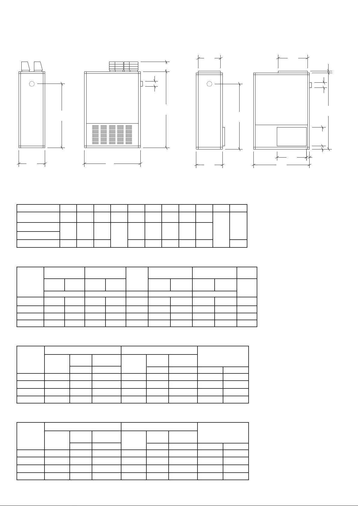
2.1 Dimensions
NCA-G 100 - 300 UF & UD Models
NCA-G 200UD SHOWN
H
D
F
C
G
B
FRONT
VIEW
A
SIDE
VIEW
B
FRONT
VIEW
Table 1 - Dimensions
A B C D F G H J K L M
NCA-G 100 1112 603 1645 254 125 1390 502 375 629
NCA-G 150
NCA-G 200 203
NCA-G 300 1390 730 2076 150 1810 629 525 756 47
1340 629 1822 125 1530 527 450 705 50
72
G
Gas connection size
All Units R½
A
SIDE
VIEW
K
L
F
C
J
K
M
M
Table 2 - Performance Data
HIGH FIRE LOW FIRE
INPUT OUTPUT
MODEL
NCA-G 100 33.3 29.3 N/A N/A 0.5192 150 N/A 0.335 N/A 152
NCA-G 150 50.0 44.0 N/A N/A 0.7788 290 N/A 0.55 N/A 215
NCA-G 200 66.9 58.6 N/A N/A 1.0383 200 N/A 0.56 N/A 215
NCA-G 300 100.0 88.0 N/A N/A 1.5575 250 N/A 1.5 N/A 304
(Net) (Net)
kw kw m³/s pa kw kg
INPUT OUTPUT
AIR
VOLUME
MAXIMUM DUCT
RESISTANCE
Standard L.H.P. Standard L.H.P.
FAN MOTOR WEIGHT
Table 3.1 - Burner Pressures - Natural Gas - Group H - G20 - NetCV (Hi) = 34.02MJ/m³
Powrmatic Burners Riello Burners
Type Pressure Pressure Type Pressure Pressure
MODEL
NCA-G 100 PCGS 2 N/A 4.8 GS 5 N/A 4.3 3.40 120.0
NCA-G 150 PCGS 2 N/A 9.9 GS 5 N/A 4.2 5.12 180.8
NCA-G 200 PCGS 3 N/A 12.2 GS 10 N/A 3.7 7.08 250.0
NCA-G 300 PCGS 5 N/A 10.4 GS 10 N/A 5.2 10.89 384.5
Start Gas Main Burner Start Gas Main Burner Gas Rate
mbar mbar mbar mbar m³/h ft³/h
Table 3.2 - Burner Pressures - Propane - G31 - NetCV (Hi) = 88.00MJ/m³
Powrmatic Burners Riello Burners
Type Pressure Pressure Type Pressure Pressure
MODEL
NCA-G 100 PCGS 2 N/A 6.9 GS 5 N/A 3.1 1.31 46.3
NCA-G 150 PCGS 2 N/A 11.3 GS 5 N/A 6.4 1.98 69.9
NCA-G 200 PCGS 3 N/A 20.0 GS 10 N/A 4.1 2.74 96.7
NCA-G 300 PCGS 5 N/A 14.2 GS 10 N/A 8.3 4.21 148.7
Start Gas Main Burner Start Gas Main Burner Gas Rate
mbar mbar mbar mbar m³/h ft³/h
2
Page 5

Table 4 Electrical Loadings
Standard Larger Horsepower Motor
NOM. PLATE START RUN FUSE NOM. PLATE START RUN FUSE
MODEL
NCA-G 100 1000 2.6 5.0 2.6 3
NCA-G 150
NCA-G 200
NCA-G 300 7.0 18.0 8.1 10
MOTOR AMPS AMPS AMPS RATING MOTOR AMPS AMPS AMPS RATING
ph R.P.M. (A) (A) (A) (A) R.P.M. (A) (A) (A) (A)
500 5.0 8.5 6.1 7
1
1000
4.1 10.0 4.5 5
N/A
3. General Requirements
3.1 Related Documents
The installation of the air heater(s) must be in accordance
with the rules in force and the relevan t requirements of th e
Gas Safety Regulations, Building Regulations and the I.E.E.
Regulations for Electrical Installations.
It should be in accor dance al so with any r ele vant r equirem ents
of the local gas region, l ocal auth ority an d fire auth ority an d
the relevant recommendations of the following documents.
British Gas Plc Publications
IM/11 : 1989 Flues for Commercial and Industrial Gas Fired
Boilers and Air Heaters
IM/16 : 1988 Guidance notes for the installation of gas
pipework, boosters and compressors in Customer’s premises
(excluding domestic installation of 25mm and below).
British Standards Code of Practice
BS 5588 Fire precautions in the design and construction of
buildings.
Part 2 : 1985 Code of Practice for Shops
Part 3 : 1983 Code of Practice for Office Buildings
BS 6230: 1991 Installation of Gas Fired Forced Convection
Air Heaters for Commercial and Industrial Space Heating.
Those appliances having an input ratin g n ot e xceedin g 60kW
viz. NCA-G 100 and NCA-G 150 mu st be install ed in accor dance
with the relev ant recomm endations of th e follo wing documen ts.
BS 5440 Flues and Air Supply for gas appliances of rated
input not exceeding 60kW (1st and 2nd family gases).
Part 1 - Flues, Part 2 - Air Supply
For NCA-G100 and NCA-G150 units reference should also be
made to BS 5864. Code of Practice for installation of gasfired ducted-air heaters of rated input not exceeding 60kW.
3.2 Location
The location chosen for the air heater must permit the
provision of a satisfactory flue system and an adequate air
supply. The location must also provide adequate space for
servicing and air circulation around the air heater.
The heater(s) must not be installed in conditions for which
it is not specifically designed e.g. where the atmospheric is
corrosive or salty and where high wind speeds may affect
burner operation, and they are not suitable for outd oor use.
Where the location of the air heater is such that it might
suffer external mechanical damage e .g. fr om ov erh ead cr anes ,
fork lift trucks, it must be suitably protected.
NCA-G units are designed to operate in a maximum ambient
temperature of 25°C.
3.3 Gas Supply
3.3.1 Service Pipes
The local gas undertaking should be consulted at the
installation planning stage in or der to establish th e availability
of an adequate supply of gas. An existing service pipe must
not be used without prior consultation with the local gas
undertaking.
3.3.2 Meters
A gas meter is connected to the service pipe b y th e l ocal gas
undertaking or a local gas un dertakin g contr actor. An existing
meter should be check ed, pr efer ably b y th e gas un d ertaking,
to ensure that the meter is adequate to deal with the total
rate of gas supply required.
3.3.3. Installation Pipes
Installation pipes should be fitted in accordance with
IM/16:1988. Pipework from the m eter to the air heater must
be of adequate size. Do not use pipes of a smaller size than
the inlet gas connection of the heater. The complete
installation must be tested for soun dn ess as d escribed in th e
above Code. The complete installation must be tested for
soundness as described in BS 6230.
3.3.4. Boosted Supplies
Where it is necessary to employ a gas pressure booster the
controls must include a low pressure cut off switch at the
booster inlet. The local gas undertaking must be consulted
before a gas pressure booster is fitted.
3.4 Flue System
Detailed recommendations for fluing are given in BS 5440,
Part 1 (Flues) and IM/11.
The air heater must be connected to a closed flue system.
The cross sectional area of the flue serving the appliance
must be not less than the area of the flue outlet to the air
heater.
Materials used for the flue system should be mechanically
robust, resistant to internal and external corrosion,
noncombustible and durable under the conditions to which
they are likely to be subjected.
Prevention of condensation within the flue should be an
important factor in the design of the flue system. In order
to minimise condensation the use of double wall ed flue pipe
or insulation is recommended. If double walled flue pipe is
used it should be of an acceptable type.
Where condensation in the flue is unavoidable provision
should be made for condensation to flo w fr eely t o a point at
which it can be released, preferably into a gully. The
condensation pipe from th e flue t o th e disposal poin t sh oul d
be of non-corrodible material o f not l ess than 22mm diameter .
Facilities should be made for disconnecting the flue pipe(s)
from the air heater(s) for inspection and servicing purposes.
Bends with removable covers shoul d be fitted for inspection
and cleaning purposes where considered appropriate.
The flue should terminate in a freely exposed position and
must be so situated as to pre v ent th e pr oduct s o f combustion
entering any opening in a building in such concentration as
to be prejudicial to health or a nuisance.
It is recommended that consideration be given to th e fittin g
of a terminal at the flue outlet, however, where the heater
flue is less than 200mm in diameter an approved terminal
must be fitted.
3.5 Air Supply
In buildings having a design air change rate of less than
0.5/h, and where NCA-G h eater s ar e to be in stall ed in h eated
spaces having a volume less than 4.7 m3 /kW of total rated
heat input grilles shall be provide at low level as follows:-
3
Page 6

(1) for heaters of heat input less than 60 kW, the total
minimum free area shall not be less than 4.5 cm2 per
kilowatt of rated heat input.
(2) for heaters of h eat input 60 kW or more, the total minimum
free area shall not be less than 270cm2 plus 2.25 cm
per kilowatt in excess of 60 kW rated heat input.
The air vent(s) should have negligible resistance and must
not be sited in any position where it is likely to be easily
blocked or flooded or in an y position a djacent t o an extr action
system which is carrying flammable vapour.
Where the air heater(s) is t o be in stall ed in a plant room the
air heater(s) requires the plant room housing it to have
permanent air vent s comm unicating dir ectly with the out sid e
air, at high l e vel an d at lo w l ev el. Wher e comm unication with
the outside air is possible only by means of high level air
vents, ducting down to floor l e v el f or the lower vent s sh oul d
be used.
Air vents should have negligible resistance an d must not be
sited in any position where th ey ar e likely to be easily bl ocked
or flooded or in any position a djacen t to an e xtra ction sy stem
which is carrying flammable vapour.
Grilles or louvres should be so designed that high velocity
air streams do not occur within the plant room.
2
clear of sources of smells and fumes, and in special
circumstances where there is any possibility of pollution of
the air by dust, shavings etc., precautions mu st be taken by
carefully positioning return air intakes and by the provision
of screens to prevent contamination.
In addition, where there is a risk of combustible material
being placed close to the warm air outlets, suitable barrier
rails should be pr ovided to preven t any combustible material
being within 900mm of the outlets.
3.7 Electrical Supply
Wiring external to the air h eater must be in stalled in accordan ce
with the I.E.E. Regulations for Electrical Installations and
any local regulation s which apply . Wirin g shoul d be completed
in flexible conduit.
Heaters NCA-G 100 - 300 are supplied by 230V - 1ph, 50Hz.
The method of connection to the main electricity supply
must facilitate the complete electrical isolation of the air
heater(s) and the supply shoul d serv e only th e air h eater(s).
The isolator must have a contact separation of at least 3mm
in all poles. The method of connection should be provided
adjacent to the air heater(s) in a readily accessible position.
See the accompanyin g wiring dia gram f or the h eater electrical
connections.
The basic minimum effective area requirements of the air
vents are as follows:
(a) Low Level (inlet)
(1) for heaters of total rated heat input less than 60
kW: 9 cm2 per kilowatt of rated heat input;
(2) for heaters of total rated heat input 60 kW or mor e:
540 cm2 plus 4.5 cm2 per kilowatt in excess of
60 kW total rated input.
(b) High Level (outlet)
(1) for heaters of total rated heat input less than 60
kW: 4.5 cm2 per kilowatt of rated heat input;
(2) for heaters of total rated heat input 60 kW or mor e:
270 cm2 plus 2.25 cm2 per kilowatt in excess of
60kW total rated input.
3.6 Air Distribution System
The following notes are of particular importance.
For free-blowing units it must be taken into account that
the buoyancy of the heated air leaving the heater and air
patterns within the space being heated will modify the air
throw pattern achieved. In buildings having a low heat loss
where single units are required to cover a large floor area
and in buildings with high roof or ceiling heights Calecon
thermal economiser units should be fitted to ensure even
heat distribution and minimise stratification respectively.
Care should be taken to avoid impeding the air throw with
racking, partitions, plant or machinery etc.
For ducted units all delivery and return air ducts, including
air filters, jointing and any insulation or lining must be
constructed entirely of materials which will not contribute
to a fire, are of adequate strength and dimensionally stable
for the maximum internal an d external temper atures t o which
they are to be exposed during commissioning and normal
operation. In the selection of materials account must be
taken of the working environment and the air temper atures
which will result when the ov erh eat limit therm ostat is being
commissioned. Where inter-joist spaces are used as duct
routes they should be suitably lined with a fire-resisting
material.
A full and unobstructed return air path to the air heater(s)
must be provided.
If the air heater(s) is installed in a plan t room the return air
intake(s) and the w arm air outl et(s) fr om th e h eater(s) m u st
be fully ducted, in to and out of the plant room to avoid
interference with the oper ation of the flue b y the air circulation
fan.
The openings in the structure of the plant room through
which the ducting passes must be fire stopped.
Care must be taken t o en sur e that return-air in tak es are k ept
4. Installation of Air Heater(s)
4.1 General
Before installation, check that the local distribution
conditions, nature of gas and pressure, and adjustment
of the appliance are compatible.
The air heater must be in stall ed in a ccor dan ce with th e rul es
in force and the r el e van t r equir emen t s of any fire regulations
or insurance company’s requirements appertaining to the
area in which the heater is located, particularly wh er e special
risks are involved such as areas where petrol vehicles are
housed, where cellulose spraying is carried out, in wood
working departments etc.
The followin g minimum clear ances for installation an d servicing
must be observed.
To the front The depth of the heater
To the rear 1.0m
To at least one side 1.0m
Above the heater 1.00m
Any combustible material adjacent to the air heater and the
flue system must be so placed or shielded as to ensure that
its temperature does not exceed 65°C.
IMPORTANT:
1. No air heater shall be installed where there is a f oreseeable
risk of flammable particles, gases vapours or corrosion
inducing gases or vapours being drawn into either the
heated air stream or the air for combustion. In such
cases installation may only proceed if the air to be
heated and the air for combustion are ducted to the
heater from an uncontaminated sour ce preferably out side
the building. In certain situations where only airborne
particles are present it may suffice to fit filters on the
air inlet ducts of the heater. Advice in these instances
may be obtained from Powrmatic Ltd.
4.2 Fitting the Air Heater
The heaters must be installed on a level noncombustible
surface.
If noise level s ar e o f particular importan ce th e h eater sh oul d
be insulated from the structure of the building by in stalling
it on suitable anti-vibration mountings. In all such cases it
is essential that all gas, duct, electrical an d flue conn ection s
to the heater are ma d e with fl e xibl e connection s t o main tain
continuity of connection. In the case of the flue connection
single wall stainless steel flue is deemed to flex sufficiently
to meet the requirements.
4
Page 7

4.3 Connection of Air Heater(s) to Flue System
A single wall Tee piece is supplied with each heater and must
be fitted to the flue outlet socket on the heater. The flue
system then connects directly on to the tee. For flue sizes
refer to Table 1, Page 2. Horizontal runs of flue are not
permitted. If necessary a single offset using two 45° bends
can be included to av oid obstructions . The maximum equival ent
resistance of the flue system must not exceed 20pa. Details
of how to calculate the resistance of the flue t o be installed
are given in Appendix A.
4.4 Condensate Drainage
The design of the flue s y stem sh oul d minimise the f ormation
of condensation, however when this is envisaged to be a
problem provision should be made for condensation to flow
to a joint where it can be drained, preferably into a gully.
4.5 Gas Connection
A servicing valve and downstream union must be fitted at
the inlet to the air heater gas controls assembly to fa cilitate
servicing. The gas supply to the air h eater m ust be compl eted
in solid pipework and be adequately supported.
Warning: When completing the final gas connection to the
heater do not place undue strain on the gas pipework of th e
heater.
4.6 Electrical Connections
All units are fully pre-wired an d only requir e final connections
for the incoming main s supply an d compl etion of th e con tr ol
circuit (230V) via a room thermostat, time clock etc. The
electrical supply must be run to a point adjacent to the
heater and be suitably terminated to provide an isolation
point that will prevent remote activation of th e unit during
servicing. The heater electrical panel is located behind the
front panel and cabl e entry poin ts are pr ovided in th e adja cent
heater framework. Reference must be ma de to Table 4 (Page
3) to ascertain the electrical loading of the air heater(s)
being installed so that cables of adequate cross-sectional
area to safely carry that load are used for the electrical
installation. The length of the conductors betw een the cord
anchorage and the terminals must be such that the current
carrying conductors become taut before the earth condu ct or
if the cable or cord slips out of the cord anchorage. All
external controls must be of an approved type.
See the wiring diagram accompanying these instructions.
5. Air Distribution System
5.1 General
NCA-G ###UD models are designed for use with duct w ork t o
more precisely defin e the poin t of air d elivery, and /or provide
ducted return air or ducted fresh air inlet. All ducting must
be independently supported of the air heater. Joints and
seams of supply ducts an d fittin g s m u st be secur ely f asten ed
and made airtight.
5.2 Noise Reduction
If deemed necessary consid eration shoul d be given to m ounting
the heater on resilient pads, or equivalent, to minimise
transfer of noise an d vibration t o the structur e of the buil ding.
It is recommended that ducting should be connected t o the
heater spigots via an airtight flexible coupling of
noncombustible material. Before fitting coupling it must be
ensured that a maximum clear ance of 13mm will be main tained
between the ends of the ducting and the heater spigots.
If required sound attenuators may be fitted in inlet and
outlet ducts to reduce airborne fan noise. Materials used in
outlet sound attenuators must be capable of withstanding
100°C air temperature without any deterioration.
temperature is concerned. Draughty areas, areas subjected
to direct heat e.g. from the sun, and areas where the air
movement is relatively stagnant e.g. in recesses, are all
positions to be avoided for siting the thermostat.
The thermostat should be mounted about 1.5m from the
floor.
Any room therm ostat, fr ost th ermostat, time clock etc. mu st
be suitable for switching 230V, 5A and must be of the 'snap
action' type to minimise contact bounce.
For electrical connections of external controls see the
accompanying wiring diagram.
6. Commissioning & Testing
6.1 Electrical Installation
Checks to ensure electrical safety must be carried out by a
competent person.
6.2 Gas Installation
The whole of th e gas in stallation, inclu ding th e meter, should
be inspected and tested for soundn ess and purg ed in accordance
with the recommendations of IM/16:1988.
6.3 Air Distribution System
The system shoul d be ch eck ed to en sur e that th e installation
work has been carried out in accordance with the design
requirements.
Particular attention shoul d be given to th e correct arran gemen t
of delivery ducts and registers, return air ducts and grills
and general adequacy of return air paths.
For NCA-G ###UD heaters ensure that the total duct system
resistance does not exceed the available air pressure of the
equipment supplied refer to Table 2, (Page 2). If the duct
system resistance is less than the available air pressure of
the equipment supplied additional resistance must be
introduced e.g. by adjustment of duct outlet nozzles and
balancing of the duct system.
6.4 Lighting the Air Heater
6.4.1 Gas Controls Assembly - Soundness Check
1. Ensure the gas service valve at the inl et to th e gas control s
assembly is shut.
2. To prove soun dn ess of th e fir st main safety sh ut-off v alv e
and first start gas safety shut-off valve:a) Connect pressure gauge to the inlet pressure test
point on the main valve block or inlet pipework.
b) Open gas service valv e and allow pressure to stabilise
before shutting it again. The valves are sound if
no pressure drop is observerved. If a pressure drop
is observed do not proceed until the fault has been
rectified. Remove pressure gauge and refit sealing
screw in pressure test point.
6.4.2 Sequence Check
1. Ensure that the gas service valve is closed and that the
main electrical supply to the heater is switched off.
2. Check that all external controls are eith er "ON" or at "MAX"
3. Turn "ON" the main electrical supply and check that the
following sequence of events occurs.
i) Burner fan runs
ii) Ignition spark is heard
iii) Main gas valves open.
iv) Burner goes to lockout as there is no gas supply.
4. Switch off main electricity supply.
6.4.3 Final Adjustment
IMPORT ANT: Th e maxium flo w and start gas flo w adju stmen ts
provided on the GM main gas block valve assembly
(Fig 2b - 4) are not used and must not be adjusted.
5.3 Room Thermostat Siting
The room thermostat should be fitted at a point which will
be generally representative of the heated area as far as
1. Remove the sealing screw from the pressure test point
located on the side of the gas inlet to the burner head
and attach a pressure gauge. Remove the sample point
5
Page 8

Fig 1 Gas Controls Schematics
1st Main Gas
Safety Shut-off
Valve
Gas
Inlet
Fig 2a Gas Controls Layout NCA-G 100, 150
1) 1st Main gas safety shut off valve.
2) 2nd Main gas safety shut off valve.
3) Main burner pressure adjustment screw.
Notes:-
i) Electrical connection plugs not shown.
Fig 2b Gas Controls Layout NCA-G 200, 300
1) Main gas safety shut-off
valves.
3
2) Main burner pressure
adjustment screw.
3) Inlet Pressure test point.
4) Flow rate and valve opening
speed adjustments.
Gas
Inlet
2nd Main Gas
Safety Shut-off
Main Gas
Governor
Inlet
1
Gas
Valve
Pressure
Test
Point
To Burner
1 2
To
Burner
3
2
4
To
T
E
P
S
O
.
I
N
G
E
T
R
T
R
A
T
S
X
V
A
M
V
3
Burner
cover plug from the outlet flue length and insert a CO
measuring instrument.
2. Turn "ON" the main electricity supply and check that the
following sequence of events occur.
i) Burner fan runs.
ii) Ignition spark is heard
iii) Main gas valves open
iv) Main gas flame is established.
3. Check that the main burner gas pressure agr ees with that
in Tables 3.1 or 3.2. If necessary adjust the main burner
gas pressure (Fig 2a - 3 or Fig 2b - 2).
4. Measure the CO2 content of the flue gases. If necessary
adjust the combustion air damper of the burner (Refer to
the Burner Supplement) to obtain a r ea din g o f 9.0 - 9.5%.
5. Turn "OFF" the main electricity supply, remove pressure
gauge and refit sealing screw in pressure test point and
flue sample point cover plug.
6.5 Final Soundness Test
1. After making final gas rate checks all joints on the gas
controls assenbly mu st be tested f or soundn ess u sing l eak
detection fluid.
6.6 Flame Safeguard
1. Whilst the burner is in operation close the gas service
valve. The burner should go to lockout within 1 second.
2
6.7 Handing over the Air Heater
Hand the Users Instructions to the user or purchaser for
retention and instruct in the efficient and safe operation of
the air heater and associated controls.
Adjust the automatic controls to those values required by
the User.
Finally, advise the user or purchaser that, for continued
efficient and safe operation of the air heater, it is important
that servicing is carried out annually.
In the event that the premises are not yet occupied turn off
the gas and electricity supplies and leave instructional
literature adjacent to gas meter.
7. Servicing
WARNING: Always switch off and disconnect electricity
supply and close the gas service valve before carrying out
any servicing work or replacement of failed components.
7.1 General
Full maintenance should be undertaken not less than once
per year. After any servicing work has been complete or any
component replaced the air heater(s) must be fully
commissioned and tested for soundness as described in
Section 6.
6
Page 9

7.2 Burner Maintenance
1. Refer to the Burner Supplemen t supplied with th e heater.
Note: Any referen ces th erein t o th e gas con trol s assembly
should be ignored.
7.3 Heat Exchanger Cleaning
1. Disconnect the gas supply at the inlet to the gas con tr ol s
assembly.
2. Disconnect the electrical connections from the heater
electrical panel to the buner at the burner.
3. Remove the nut s securing the burn er to the h eat exchan ger
and remove the burner.
4. Remove the fan/limit thermostat as described in 7.5.4
and then remove the inner panel of th e h eater t o expose
the heat exchanger clean out panel. Remove the nuts
securing the panel and remove the panel.
5. Remove the nuts securing the heat exchanger baffles
retention strip and remove strip.Withdraw the baffles.
6. Brush through heat exchanger tubes and remove loose
material using a vacuum cl eaner . R emove an y loose material
from the base of the combu stion chamber , workin g through
the burner port.
7. Reassemble all components in reverse order. Inspect all
gaskets and replace if necessary.
7.4 Fan Assembly
1. Remove the upper and lower side panels on one side of
the heater to gain access to the fan.
2. Inspect the fan blades to see that they are not damaged
and that there is no excessive build up of deposits that
could give rise to an imbalance. If necessary clean the
fan blades using a stiff brush and vacuum cleaner. If it
is required to rem o v e th e fan f or cl eanin g r efer t o section
7.4.3
7.5 Replacement of Faulty Components
the heater.
3. Remove the two set screws, one on each side of the fan
mounting flange, the secure the fan to the fan shroud.
4. Withdraw the fan from the slide rails.
5. Reassemble in reverse order.
7.5.4 Fan and Limit Thermostat (Honeywell L4064N )
1. Release the single screw securing the fan and limit
thermostat cover and remove cover by pulling forward.
2. Release wiring from clamp terminals by pushing a small
screwdriver into the clamp release holes adjacent to the
clamps.
3. Remove the 2 scre ws securin g the therm ostat to th e heater
panel and withdraw thermostat.
4. Reassemble new unit in reverse order refering to the
heater wiring diagram to ensure correct wiring location.
Fig 3 Honeywell L4064N
Set Point Dial
Fan Circuit
Summer /
Winter
Switch
0
2
T
CAUTION
DO NOT ROTATE - HOLD
2
0
DIAL WHEN SETTING POINTERS
4
1
I
M
I
0
L
0
F
N
A
1
0
8
0
6
0
Limit Circuit
Limit Reset
7.5.1. Burner Components
1. Refer to the burner supplemen t supplied with th e h eater.
7.5.2 Gas Controls Assembly
7.5.2.1 NCA-G 100, 150
7.5.2.1.1 Gas Valve Coil.
1. To fit a new valve operating coil remove the electrical
supply plug, release the securing nut on top of the valve
stemand remove the nut and washer. Lift of the faulty
coil and fit the new coil in reverse order.
7.5.2.1.2 Block Valve Assemby.
1. Remove the electrical supply plug,
2. Release the unions on the connection s at ea ch end o f th e
assemby and remo ve compl ete assembly. Fit new assembly
in reverse order ensuring the valv e assembly is correctly
orientated for the direction of gas flow.
7.5.2.2 NCA-G 200, 300
7.5.2.2.1 Block Valve Assembly.
1. Release the union on the gas service valve
2. Remove the electrical conn ection from th e valv e assembly.
3. Release the socket head cap scr ews securin g the connection
flanges to the main gas bl ock v alve an d rem o ve th e block.
Fit new assembly in reverse order ensuring correct
orientated for the direction of gas flow.
7.5.3 Main Air Fan and Motor
Note: On heaters supplied as specials with 3ph m ot ors en sure
that the fan direction of rotation corresponds with the
direction of rotation arrow on the fan guard or case. If
necessary reverse the direction of rotation by in terchanging
any two of the motor live leads at the terminal strip in the
electrical panel.
1. Disconnect the fan motor electrical l ea ds fr om th e h eater
terminal strip (Refer to the Wiring Diagram supplied)
2. Remove the upper and lower side panels on one side of
Limit CircuitFan Circuit
Jumper Location
Important: As supplied by the Manufacturer this fan/limit
thermostat is fitted with a brass jumper between th e bott om
fan terminal and the bottom limit terminal (situated in the
slot between the two terminals). This MUST be removed, by
using a pair of thin nose pliers, before the replacement
thermostat is installed.
5. Ensure that the fan and limit settings are as follows:Fan ON 50°C
Fan OFF 30°C
Limit 110°C
8. Connections to Powrmatic External Contr ols
8.1 Powrtrol
NCA-G
Terminals Terminals
connect to
1 1
2 2
8 5
9 6
Powrtrol
8.2 Eurotrol
NCA-G
Terminals Terminals
connect to
1 CTRL CCT
2 CTRL CCT
8 FAN CCT
9 FAN CCT
Eurotrol
7
Page 10

9. Fault Finding
Refer also to the burner supplement supplied with the heater
Fault Cause Action
Main burner will not light Electrical 1. Check electrical and gas supplies are ON.
2. Check controls are ON or calling for heat.
Main burner lights, but goes Electrical 1. Unit goes out on high limit out before main fan comes on. a. Check fan thermostat setting - See Section
7.6.5.
b. Faulty fan thermostat - change
c. Check limit thermostat setting - See Section
7.6.5.
d. Faulty limit thermostat - change.
2. Faulty fan assembly - change.
3. (Ducted Units Only) -fan motor out on thermal
overload. - Check running amps. See table 4.check duct resistance See Table 5.
Main fan runs continuously Electrical 1. Summer/Winter switch set to Summer.
2. Fan thermostat set too low - check setting. See
Section 7.6.5
3. Faulty fan thermostat - change
Main fan fails to run Electrical 1. Fan motor or capacitor failed - replace.
2. Fan thermostat faulty - replace.
3. Fan contactor failed - replace (3ph units)
10. Short List of Parts
Refer also to the burner supplement supplied with the heater.
Refer to Powrmatic Ltd for the details of any parts not listed here.
ITEM APPLICATION PART NUMBER
Johnson Controls GM-7742-3503 - ½"BSP. 100, 150 141379957
Johnson Controls GM-2540-2000 - ¾"BSP 200, 300 141379954
Thermostat - Fan / Limit Honeywell L4064N. ALL 143000303
Heat Exchanger Cleanout Door Gasket. ALL 170246006
Pressure Relief Door Gasket - 114mm dia. ALL 142202110
Pressure Relief Door Gasket - 95mm dia. ALL 142202257
Pressure Relief Door Gasket - 166mm x 166mm. ALL 142202310
Burner Gasket - Nu-Way PCGS 2/3/5. ALL 144704004
Burner Gasket - Riello GS5. 100 141937080
Burner Gasket - Riello GS510 150 - 300 141930806
8
Page 11

Appendix A
Calculation Of Flue System Equivalent Resistance
The pressure resistance of the flue system (Pr) can be calculated from
Pr = 1.5 * [(PFF*H/D+SRF)Q
m/Wm
2]
Where Pr = Pressure resistance of the flue system in pa
PRF = Pipe Friction Factor
H = Effective flue height in m
D = Internal Diameter of flue in m
SRF = Sum of individual resistance factors
Q
= Mean Density of the column of exhaust gas in kg/m
m
W
= Mean exhaust gas velocity in m/s
m
PRF
3
Can be calculated from
PRF = 0.118*(0.21147/D
0.4
)
Where D = Internal Diameter of flue in m
SRF
Typical resistance factors for individual components are as follows
Segmented 90° bend 0.5
45° Elbow 0.4
Cowl 1.0
Q
m
Q
= 97000/(300*Tm)
m
Where The mean temperature of the column of exhaust gas (T
T
= 288+((Te-TL)/0.2)*(0.18)
m
Where Te is the exhaust gas temperature in °C
T
W
m
L is the external air temperature in °C
Wm = M/(A*Qm)
Where A is the cross sectional area of the flue in m
2
M is the exhaust gas mass flow in kg/s which is as follows for the various units
m) can be calculated from
Page 12

BSI Registered Firm
FM 414
Ind. & Comm. Air Heaters;
Air Moving Equipment;
Flues & Chimneys; Natural
Smoke & Heat Ventilators;
Powered Supply & Extract
Fans & Systems.
HEATING DIVISION
Winterhay Lane
Ilminster, Somerset TA19 9PQ
Tel: 01460 53535 Fax: 01460 52341
Every effort is made to ensure accuracy at time of going to press. However as part of our policy of continual product improvement, we reserve the right to alter specifications without prior notice.
 Loading...